

Page 1
Duct and Outside Air Humidity (H200-H300)
4 to 20mA or 0 to 5V Humidity Output with Optional Temperature Sensor
Installation and Operating Instructions
9938_ins_hum_temp_duct_out_5_20
Overview
The BA/(H200, H300) is a humidity transmitter which comes in 2% or 3% accuracies and an optional temperature sensor.
The temperature sensor can be either a Thermistor or RTD. It can be ordered for either Duct or Outside Air applications with
Weatherproof (WP), Weather Tight (EU), BAPI-Box (BB), or BAPI-Box 2 (BB2) Enclosures. The transmitter can be wired for
either a 0 to 5VDC output or a loop powered 4 to 20mA output.
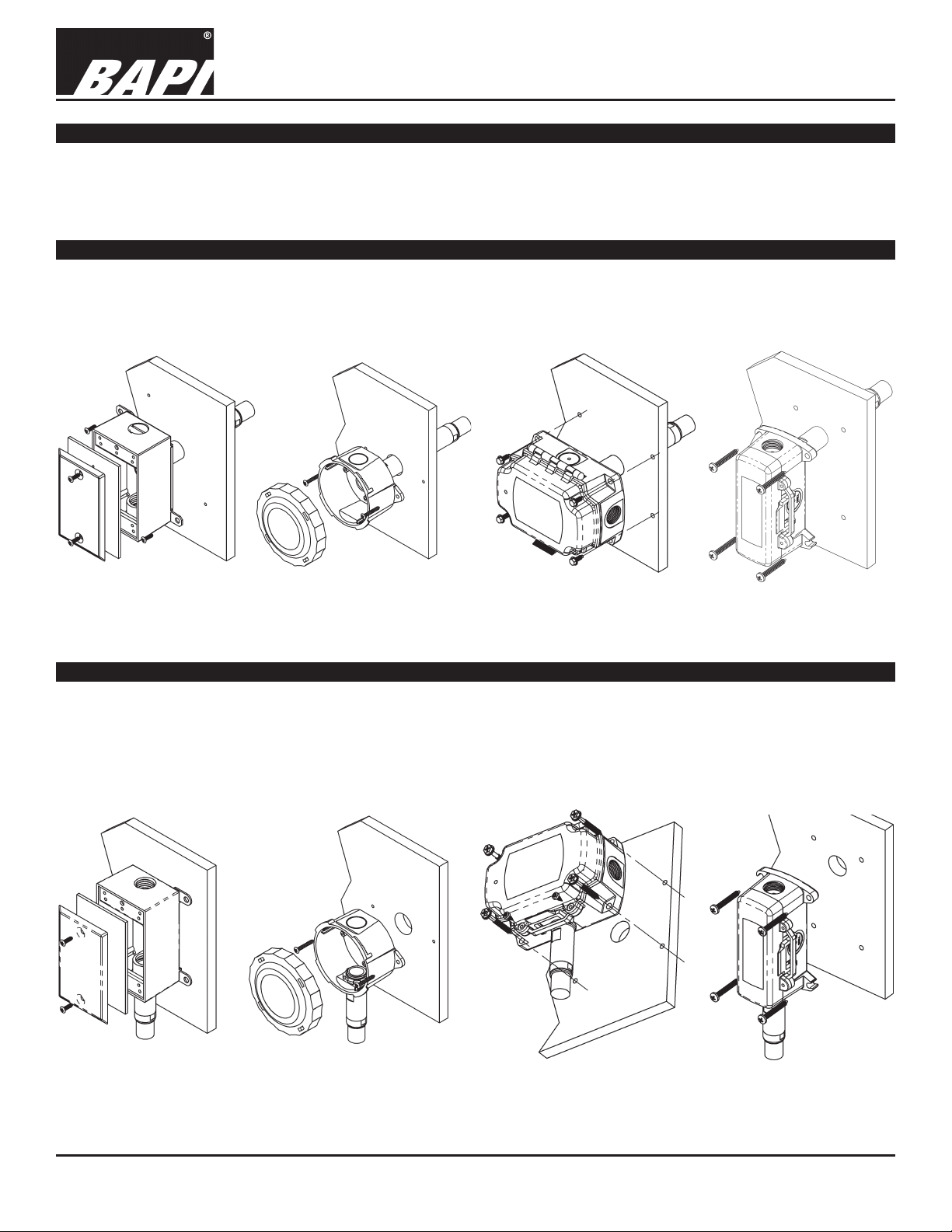
Duct Unit Mounting
Mount at least 3 duct diameters from humidiers in the center of the duct wall. Drill a 1 inch hole for the probe in the duct
and use two number 8 sheet metal screws to attach the sensor to the duct. Center the probe in its mounting hole. Be sure
that the foam seals the hole, do not over tighten the screws.
rev. 02/15/18
Fig. 1: Duct Humidity
in a Weatherproof
(WP) Enclosure
Fig. 2: Duct Humidity
in a Weather Tight (EU)
Enclosure
Fig. 3: Duct Humidity
in a BAPI-Box (BB)
Enclosure
Fig. 4: Duct Humidity
in a BAPI-Box 2 (BB2)
Enclosure
Outside Air Mounting
Mount in a permanently shaded area away from windows and doors. Do not mount in direct sunlight. Mount with the sensor probe pointed down. Drill a hole large enough for your sensor cable through your mounting surface. Mount the unit to
the surface with the wiring knock out centered over the wiring hole. Pull the wiring into the unit and terminate using sealant lled connectors. Best practice is to seal the wiring hole with caulk after the wiring is installed. Be sure that the foam
on the back of the unit makes a good weather tight seal.
Fig. 5: Outside Humidity
in a Weatherproof (WP)
Enclosure
Fig. 6: Outside Humidity
in a Weather Tight (EU)
Enclosure
Specications subject to change without notice.
Fig. 7: Outside Humidity
in a BAPI-Box (BB)
Enclosure
Fig. 8: Outside Humidity
in a BAPI-Box 2 (BB2)
Enclosure
1 of 4
Page 2
Duct and Outside Air Humidity (H200-H300)
Table 1: Humidty Transmitter with 4 to 20mA Output
Red Power 10 to 35VDC
White
Black GND (Common) Ground for Power and Humidity Output
2.2KΩ Brown/White 1KΩ Orange/Orange
3KΩ Yellow/Black
3.25KΩ Brown/Green 1KΩ Green/Green
10K-3Ω Yellow/Red
10K-3(11K)Ω Yellow/Blue 100Ω Red/Red/Black*
50KΩ White/Blue
100KΩ Yellow/White
Additional sensors are available so your sensor may not be listed on this table.
4 to 20mA or 0 to 5V Humidity Output with Optional Temperature Sensor
Installation and Operating Instructions
9938_ins_hum_temp_duct_out_5_20
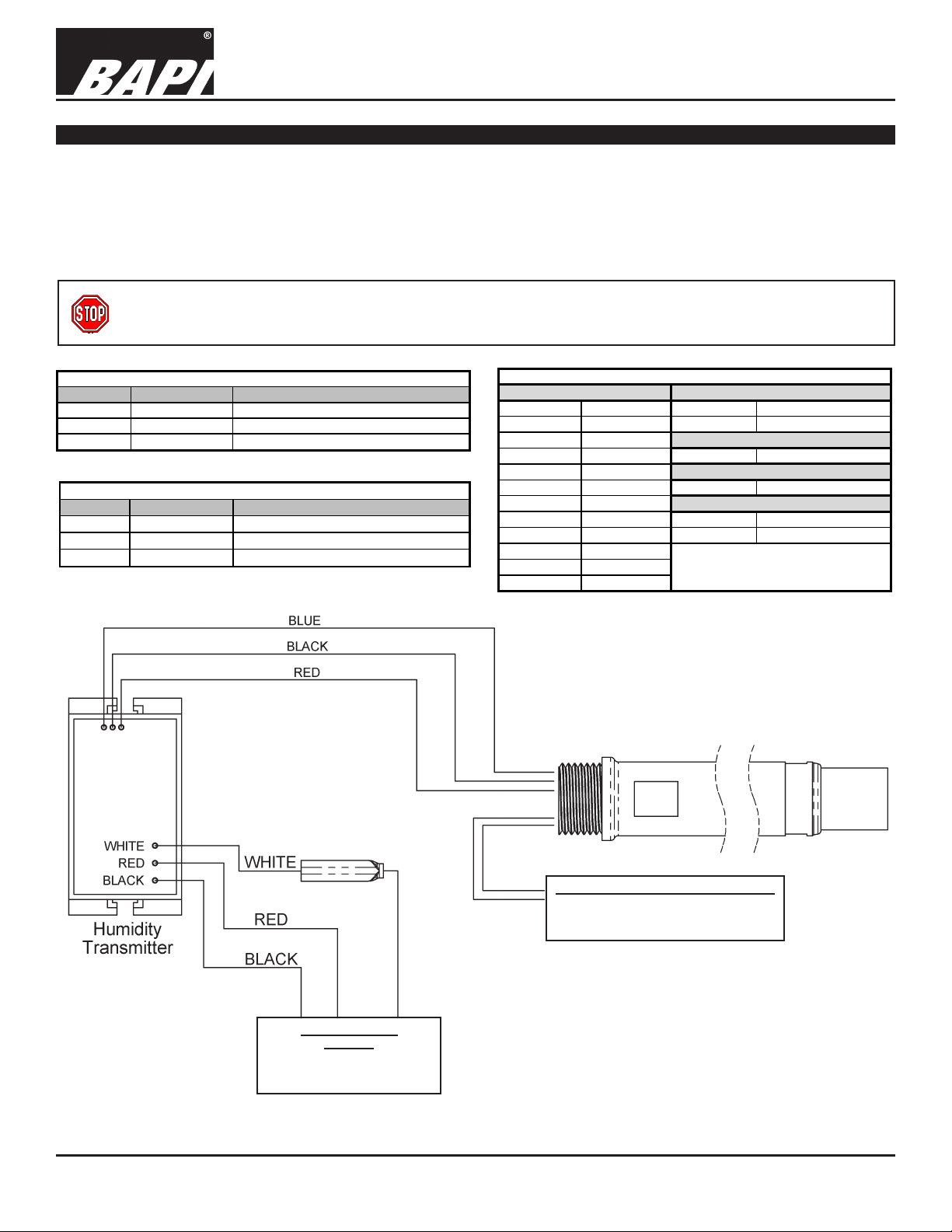
Wiring and Termination
BAPI recommends using twisted pair of at least 22AWG and sealant lled connectors for all wire connections. Larger
gauge wire may be required for long runs. All wiring must comply with the National Electric Code (NEC) and local codes.
Do NOT run this device’s wiring in the same conduit as AC power wiring of NEC class 1, NEC class 2, NEC class 3 or with
wiring used to supply highly inductive loads such as motors, contactors and relays. BAPI’s tests show that uctuating and
inaccurate signal levels are possible when AC power wiring is present in the same conduit as the signal lines. If you are
experiencing any of these difculties, please contact your BAPI representative.
BAPI recommends wiring the product with power disconnected. Proper supply voltage, polarity, and
wiring connections are important to a successful installation. Not observing these recommendations may
damage the product and will void the warranty.
Table 3: Temperature Sensor Lead Wire Colors
Wire Color Purpose Note
White Not Used Not Used (Cap Wires)
Black Humidity Output 4 to 20 mA, To Analog Input of Controller
Thermistors Platinum RTDs - 2 Wire
1.8KΩ Orange/Red 100Ω Red/Red
Nickel RTD
rev. 02/15/18
Table 2: HumidityTransmitter with 0 to 5VDC Output
Wire Color Purpose Note
Humidity Output 0 to 5VDC, To Analog Input of Controller
Red Power 10 to 35VDC or 12 to 27 VAC
3.3KΩ Yellow/Brown
10K-2Ω Yellow/Yellow 2KΩ Brown/Blue
20KΩ W hite/White 1KΩ Orange/Orange/Black*
47KΩ Yellow/Orange
Optional Temperature Sensor Output
See Table 3 above for Wire Colors
(Sensors are not polarity sensitive,
3 wires used for 3-wire RTDs)
*In the 3-Wire RTD sensors listed above,
the two wires of similar color are
Silicon RTD
Platinum RTDs - 3 Wire
connected together.
Humidity Output
& Power
See Tables 1 and 2 above
for Wiring Information
Specications subject to change without notice.
Fig. 9: Wiring Diagram
NOTE: BAPI’s 2% and 3%, humidity transmitters ARE
polarity sensitive as well as reverse polarity protected.
2 of 4
Page 3

Duct and Outside Air Humidity (H200-H300)
4 to 20mA or 0 to 5V Humidity Output with Optional Temperature Sensor
Installation and Operating Instructions
9938_ins_hum_temp_duct_out_5_20
Specications
Power:
10 to 35 VDC For 0 to 5 VDC or 4 to 20 mA Humidity Outputs
12 to 27 VAC For 0 to 5 VDC Humidity Output
Power Consumption:
22 mA max. DC For 0 to 5 VDC or 4 to 20 mA Humidity Outputs
0.53 VA max. AC For 0 to 5 VDC Humidity Output
Sensor: Factory corrected @17 RH points (10 to 90% RH)
Humidity Capacitive Polymer
RH Accuracy ±2% @ 73°F (23°C) from 10 to 90%
Drift 0.5% per year
Response time < 5 seconds in moving air
RH Linearity Negligible, factory corrected linear from 10 to 90%
RH Hysteresis Factory corrected to <1%
Opt. Temp. Passive RTD or Thermistor
Filter: 80 micron sintered stainless steel lter
Calibrated Accuracy: Calibration @17 RH points, (10% to 90%)
RH 2% 2% from 10 to 90% @ 73°F (23°C), Non-condensing
RH 3% 3% from 10 to 95% @ 73°F (23°C), Non-condensing
Thermistor ±0.36ºF (0.2ºC) from 32 to 158ºF (0 to 70ºC) - High accuracy units are available
RTD ±0.55ºF (0.31ºC) @ 32ºF (0ºC) - High accuracy units are available
Output: Selectable via wiring detail
Humidity 0 to 5VDC or 4 to 20mA at 0 to 100% RH
Opt. Temp. Resistance RTD or Thermistor
Humidity Output Impedance:
Current 700W@ 24VDC, Voltage drop is 10VDC
(Supply Voltage DC – Transmitter voltage drop 10VDC) / 0.02 Amps = Max load Impedance
Voltage 10KW
Probe Length:
Duct 5.3” (13.5cm) Duct Insertion, 1” diameter
Outside Air 2.4” (6.1cm) Below Enclosure, 1” diameter
Dimensions: W x H x D
Weatherproof (WP) 2.75” x 4.5” x 2.2”, (70 x 114 x 55 mm)
Weather Tight (EU) 4.1”x 3.8” x 2.1”, (105 x 97 x 54 mm)
BAPI-Box (BB) 4.15” x 5” x 2.5”, (105.4 x 127 x 63.5mm)
BAPI-Box 2 (BB2) 4.9” x 2.8” x 2.35”, (124.8 x 71.6 x 59.7mm)
Termination: Open wire
Crimp 18 to 26 AWG with Sealant Filled Crimp Connector (BA/SFC1000-x00)
Wire Nut 26 to 16 AWG with Sealant Filled Wire Nut (BA/SFC2000-x00)
Enclosure Material:
Weatherproof (WP) Cast Aluminum
Weather Tight (EU) ABS plastic, UV resistant
BAPI-Boxes (BB, BB2) Polycarbonate, UV resistant
Enclosures Ratings:
Weatherproof (WP) NEMA-3R
Weather Tight (EU) IP66, UL94V-0
BAPI-Boxes (BB, BB2) NEMA-4, IP66, UL94V-0
Environmental Operation Range: -40º to 158ºF (-40º to 70ºC) • 0% to 100% RH
Approvals: RoHs
rev. 02/15/18
Specications subject to change without notice.
3 of 4
Page 4
Duct and Outside Air Humidity (H200-H300)
4 to 20mA or 0 to 5V Humidity Output with Optional Temperature Sensor
Installation and Operating Instructions
9938_ins_hum_temp_duct_out_5_20
Filter Care
A sintered lter protects the humidity sensor from various airborne particles and may need periodic cleaning. To do this,
gently unscrew the lter from the probe. Rinse the lter in warm soapy water and rinse until clean. A
nylon brush may be
used if necessary. Gently replace the lter by screwing it back into the probe. The lter should screw all the way into the
probe. Hand tighten only. If a replacement lter is needed, call BAPI.
BA/HDOFS3 Stainless Steel Sintered Filter Replacement for Outside Air Units
Humidity Diagnostics
Possible Problems:
Unit will not operate
Possible Solutions:
- Check for proper supply power. (See page 2 for wiring diagram and power
specications)
rev. 02/15/18
Humidity output is at its maximum
value of 5V or 20mA
Humidity output is at its minimum
value of 0V or 4mA
Humidity reading in controller’s
software appears to be off by
more than the specied accuracy
Output Humidity Formula
4 to 20mA %RH =(mA-4)/0.16
0 to 5VDC %RH = V/0.05
Temperature Diagnostics
Possible Problems:
Controller reports Incorrect
temperature
- Make sure the humidity sensor is wired properly.
- Make sure the humidity sensor is wired properly.
- Check all software parameters
- Determine if the sensor is exposed to an external air source different from the
intended measured environment or reference device.
- Check the Humidity transmitter output against a calibrated reference such as a
2% accurate hygrometer. Measure the humidity at the sensor’s location using the
reference meter, then calculate the humidity transmitter output using the humidity
formula at left. Compare the calculated output to the actual humidity transmitter
output (see the wiring diagram on page 2 for the humidity transmitter output wire
colors). If the calculated output differs from the humidity transmitter output by more
than 5%, contact BAPI technical support.
Possible Solutions:
- Conrm the input is set up correctly in the controller’s software
- Verify that the sensor wires are not physically shorted or open
- Check wiring for proper termination
- Measure the temperature at the temperature sensor’s location using an
accurate temperature standard. Disconnect the temperature sensor wires and
measure the temperature sensor’s resistance with an ohmmeter. Compare the
temperature sensor’s resistance to the appropriate temperature sensor table on
the BAPI website. If the measured resistance is different from the temperature
table by more than 5%, call BAPI technical support. BAPI’s web site is found at
www.bapihvac.com; click on “Resource Library” and “Sensor Specs” then click on
the type of sensor you have.
Specications subject to change without notice.
4 of 4
 Loading...