

Page 1
AD592/LM334/AD592-10K/LM334-10K Room Sensors
Sensor Termination and Troubleshooting
9557_ins_592_Room
Termination
BAPI recommends using twisted pair of at least 22AWG and sealant filled connectors for all wire connections. Larger
gauge wire may be required for long runs. All wiring must comply with the National Electric Code (NEC) and local codes.
Do NOT run this device’s wiring in the same conduit as AC power wiring of NEC class1 or NEC class 2, NEC class 3 or with
wiring used to supply highly inductive loads such as motors, contactors and relays.
BAPI’s tests show that fluctuating and inaccurate signal levels are possible when AC power wiring is present in the
same conduit as the signal lines. If you are experiencing any of these difficulties, please contact your BAPI representative.
BAPI does not recommend wiring the sensor with power applied as accidental arcing may damage the product
and will void the warranty.
rev.
8/22/12
AD592/LM334 (2 Wire) sensors
1. Install a 10K 0.1% resistor between the sensor
Output (terminal 2) and Ground (GND).
2. Make sure that the resistor is connected between the analog input (A.I.) point and Ground.
3. Connect the sensor Output to the A.I. point.
4. Connect the 5 to 30 VDC wire last.
AD592-10K/LM334 (3 Wire) sensors
1. All AD592-10K/LM334-10K (3 wire) sensors
have a 10K 0.1% resistor built in.
2. Connect the Ground (terminal 3) wire first.
3. Connect the Sensor Output wire second.
4. Connect the 5 to 30 VDC wire last.
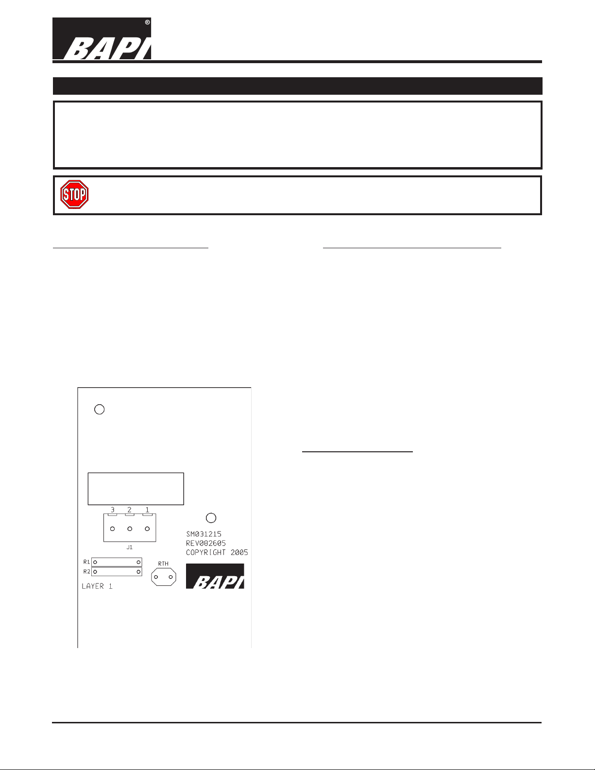
Sensor Termination
Pin 1..... Power
To Controller power output or auxiliary supply
Pin 2..... Current Output for 2-wire
Voltage Output for 3-Wire
To Analog Input of Controller
Fig 1:
Semiconductor Room Board
Pin 3..... Shorted to Pin 2 for 2-wire
Ground for 3-wire
To Controller Ground 3-Wire ONLY
Specifications subject to change without notice.
Page 2
AD592/LM334/AD592-10K/LM334-10K Room Sensors
Sensor Termination and Troubleshooting
8/22/12
9557_ins_592_Room
Theory of Operation
The AD592/LM334 sensor is a two terminal integrated-circuit temperature sensor. The AD592/LM334 provides an
output current directly proportional to absolute temperature. When the temperature of the AD592/LM334 sensor
changes one-Kelvin (one -degree Celsius), then the current through the AD592/LM334 changes by 1uAmp. 77°
Fahrenheit (25° Celsius) is 298.2 Kelvins and the output current from the AD592/LM334 sensor is 298.2uAmp.
Initial accuracy of the AD592/LM334 temperature sensor is ± 8.1° Fahrenheit (± 4.5° Celsius) at 77° Fahrenheit (25°
Celsius).
Since most meters that field technicians use cannot accurately measure currents this low, BAPI recommends that
a 10K 0.1% resistor be placed between the sensor
output and ground. The 10K resistor changes the
current into a voltage that varies 0.01 volts per one degree
Celsius temperature change; the voltage at 77°F is 2.982
VDC. Resistors with other tolerances can be used, but
you will have greater temperature uncertainty, see the
10K uncertainty table;
BAPI provides two styles of room sensor with an AD592/LM334 sensor, one with and one without the 10,000 ohm
0.1% resistor. The one with the resistor has three terminals - 1 is power, 2 is sensor output (1mV/°K) and 3 is
Ground. The one without the resistor has two terminals - 1 is power and 2 is sensor output (1uAmp/°K).
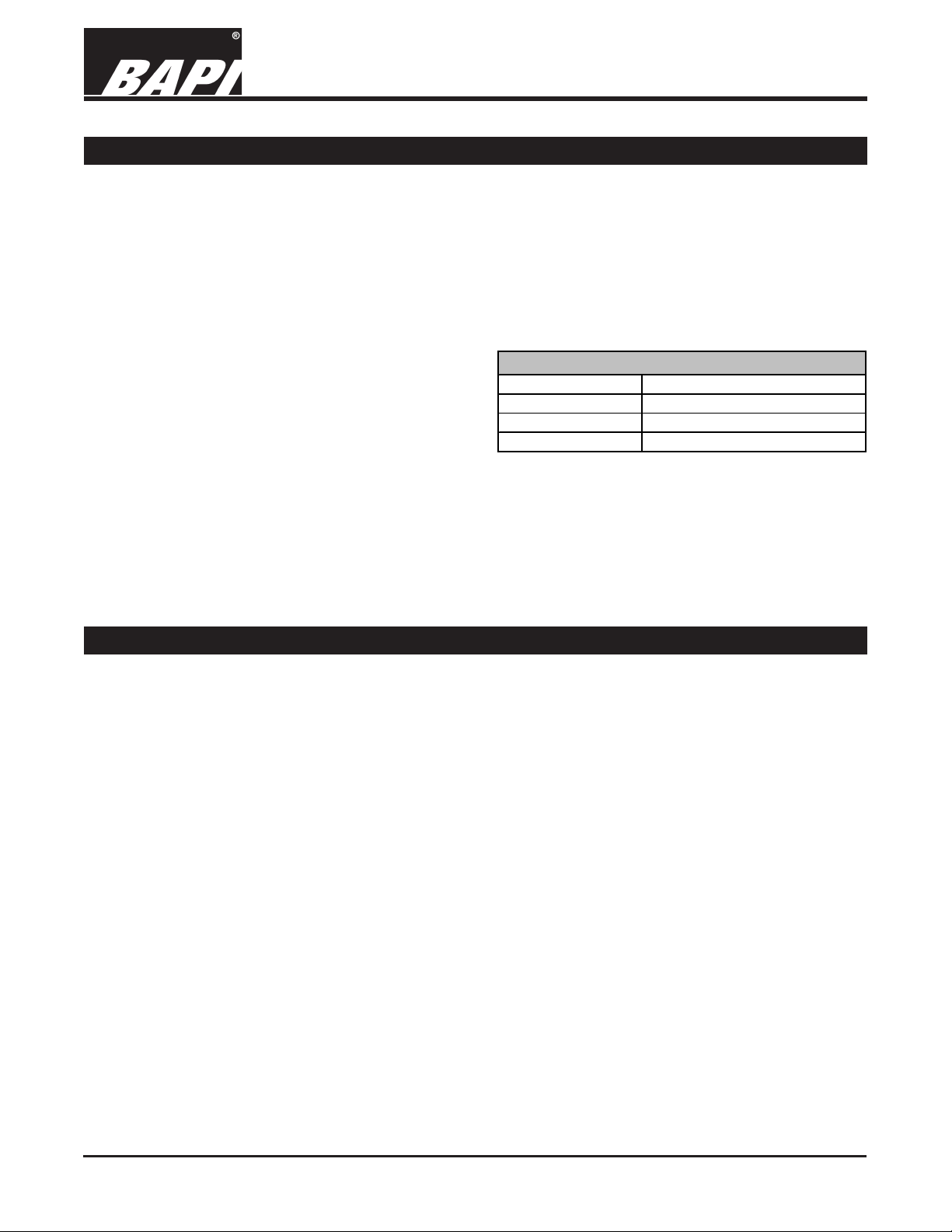
10K Uncertainty Table
Tolerance Tempera ture Uncertainty
0.10% ±8.64°F
1% ±13.47°F
5% ±34.93°F
rev.
Offsetting
All BA592 sensors will have the following information provided on a label:
Therm Reading_______
The actual temperature reading
according to a thermometer that is
certified traceable to recognized
standards by the National Institute of
Standards and Technology (NIST).
To correct the Sensor Reading, simply add the offset value to the sensor reading so that it equals the thermometer
reading.
e.g. Therm Reading 74.6 Sensor Reading 73.0 Offset +1.6
Correction: Add (+1.6) °F to the sensor for an accurate reading: 73 + 1.6 = 74.6°F
e.g. Therm Reading 75.4 Sensor Reading 77.2 Offset -1.8
Correction: Add (-1.6) °F to the sensor for an accurate reading: 77.2 + (-1.8) = 75.4°F
Sensor Reading ______
The temperature reading according to
the AD592/LM334 sensor, using the
output in either mA or mV and
converting the output to a Fahrenheit
temperature.
Offset_______
The difference between the
Thermometer Reading and the
Sensor Reading
Specifications subject to change without notice.
Page 3
AD592/LM334/AD592-10K/LM334-10K Room Sensors
9557_ins_592_Room
Troubleshooting
Sensor Termination and Troubleshooting
8/22/12
rev.
Problems:
Temperature sensor in front end software is
reading high
Temperature sensor in front end software is
reading low
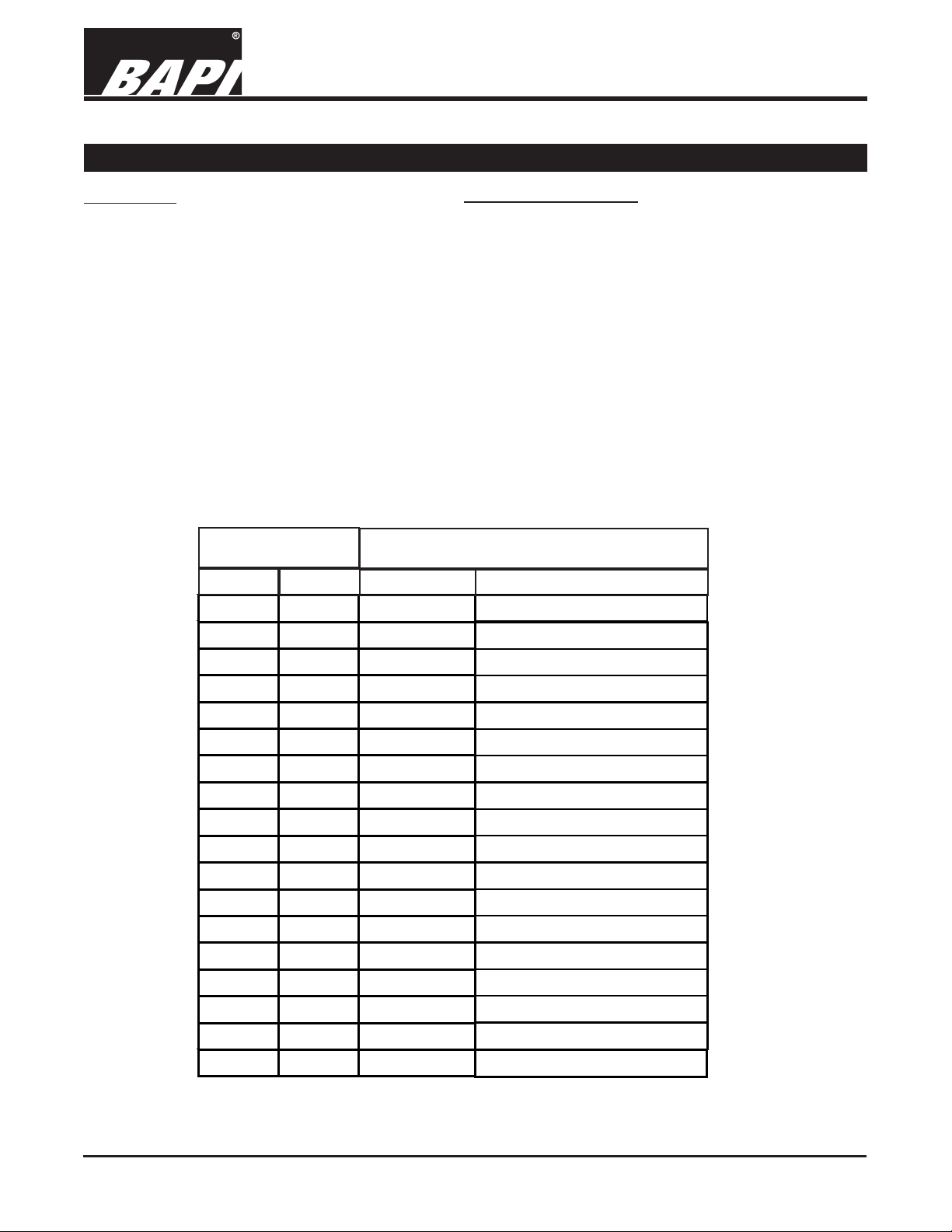
Temperature
°F
°C
50 10 283.2
60 15.56 288.76
Possible Solutions:
- Confirm the input is set up correctly in the front
end software
- Check wiring for proper termination
- Verify the “Sensor” output is correct from Pin 2 to
Pin 3. Refer to table below for proper reading
- Determine if the semiconductor appears physically shorted
- Check wiring for proper termination
- Verify the “Sensor” output is correct from Pin 2 to
Pin 3. Refer to table below for proper reading
Semiconductor Output
μA Voltage across 10K
2.832
2.8876
resistor
62 16.67 289.87
64 17.78 290.98
66 18.89 292.09
68 20 293.2
70 21.11 294.31
72 22.22 295.42
74 23.33 296.53
76 24.44 297.64
78 25.56 298.76
80 26.67 299.87
82 27.78 300.98
84 28.89 302.09
86 30 303.2
88 31.11 304.31
90 32.22 305.42
100 37.78 310.98
2.8987
2.9098
2.9209
2.932
2.9431
2.9542
2.9653
2.9764
2.9876
2.9987
3.0098
3.0209
3.032
3.0431
3.0542
3.1098
Specifications subject to change without notice.
Page 4

9557_ins_592_Room
Mounting
Fig. 2
Delta Style Room
Unit Junction Box
installation
AD592/LM334/AD592-10K/LM334-10K Room Sensors
Sensor Termination and Troubleshooting
8/22/12
rev.
Fig. 3
BAPI-Stat 2 Style
Room Unit Junction
Box installation
Mounting hardware is provided for both junction box and drywall installation (junction box installation shown).
JUNCTION BOX
1. Pull the wire through the wall and out of the junction box, leaving about six inches free.
2. Pull the wire through the hole in the base plate.
3. Secure the base to the box using the #6-32 x 1/2 inch mounting screw provided.
4. Terminate the unit according to the guidelines in Termination on page 1.
5. Attach Cover by latching it to the top of the base, rotating the cover down and snapping it into place.
6. Secure the cover by backing out the lock-down screws using a 1/16" allen wrench until they are flush with the
bottom of the cover.
DRYWALL MOUNTING
1. Place the base plate against the wall where you want to mount the sensor.
2. Using a pencil mark out the two mounting holes and the area where the wires will come through the wall.
3. Drill two 3/16" holes in the center of each marked mounting hole. Insert a drywall anchor into each hole.
4. Drill one 1/2" hole in the middle of the marked wiring area.
5. Pull the wire through the wall and out of the 1/2" hole, leaving about six inches free.
6. Pull the wire through the hole in the base plate.
7. Secure the base to the drywall anchors using the #6 x 1 inch mounting screws provided.
8. Terminate the unit according to the guidelines in Termination on page 1.
9. Attach Cover by latching it to the top of the base, rotating the cover down and snapping it into place.
10. Secure the cover by backing out the lock-down screws using a 1/16" allen wrench until they are flush with the
bottom of the cover.
NOTE
In a wall-mount application, the wall temperature and the temperature of the air within the wall cavity can cause
erroneous readings. The mixing of room air and air from within the wall cavity can lead to condensation, erroneous
readings and premature failure of the sensor. To prevent these conditions, seal the conduit leading to the junction
box and seal the hole in the drywall by using an adhesive backed, foam insulating pad (order part number BA/
FOAMBACK).
Specifications subject to change without notice.
 Loading...