

Page 1
Installation and Operating Instructions
17614_ins_wireless_900_rcvr
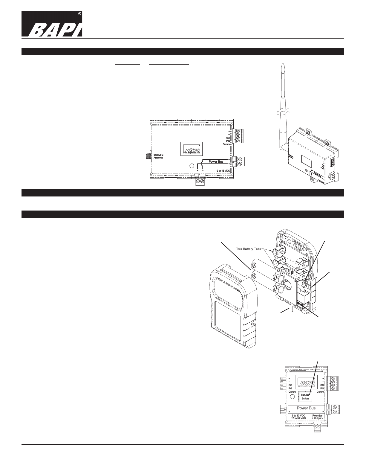
Overview and Identication
The BAPI 900 MHz unit receives a repeated or re-transmitted RF signal from one
or more wireless temperature or humidity transmitters. The signal from the transmitter
(418 MHz) is received by a BAPI Repeater and then re-transmitted at 900 MHz up to
1,000 feet to the 900 MHz Receiver.
The receiver then outputs the values to any Analog Output Module through an RS485
four-wire bus. The Analog Output Modules convert the signal to an analog voltage,
current or resistance for the controller. The receiver can accommodate up to 127
different Analog Output Modules. It is surface, snaptrack or DIN rail mountable with a
79” extendable antenna for optimum reception.
Note: The 900 MHz Receiver will only
receive a signal from a Repeater. It will not
receive the signal from the transmitters,
which transmit at 418 MHz.
Fig. 1: Two views of the 900
MHz Receiver.
Customer Provided Tools and Materials
#2 Philips Screwdriver, Drill, Wire
Wireless 900 MHz Receiver
rev. 04/21/15
Analog Output Module Training
The installation process requires that each transmitter is trained to
its associated output module or modules so that they receive communications from the correct transmitter. Pushing buttons in a de-
Battery polarity
important or damage
to the unit may occur
ned sequence on the transmitter and output module will bind the
two units together. The training process is easiest on a test bench
so that the transmitter and receiver/output modules are within
arm’s reach of each other. Training can be done in the eld but will
require two people and a set of walkie talkies or cell phones. Be
sure to place a unique identication mark on the transmitter and
associated output module or modules after they have been trained
so that they can be matched together at the job site.
If more than one variable is transmitted by the room transmitter
(temperature, humidity and setpoint for instance), each variable
requires a separate output module. Perform the training sequence
for each output module. Any transmitted variable can be trained to
more than one output module.
TEMPERATURE OR HUMIDITY VARIABLE TRAINING
1. To train an output module to a Temperature or Humidity
variable, select the Resistance, Voltage or Current Output Module calibrated to the
temperature or humidity range you need and connect it to the wireless receiver. Note:
Multiple output modules can be trained to the same transmitter variable if desired.
2. Apply power to the receiver which will supply power to the connected output modules.
The power LED on the receiver will light and remain lit. (Current Output Modules
must have loop power supplied to the module itself before they can be trained.)
3. Remove the cover of the room transmitter and remove the battery tabs or install the
batteries, observing polarity as shown in Fig 2. The small LED at the bottom right of
the circuit board, next to the setpoint, will ash approximately once every 20 seconds,
indicating a transmission. (The ash is very quick.)
Training
Button
Override
Button
Setpoint
Slider
Fig. 2: Room Transmitter with
Optional Setpoint and
Override.
Service Button
Transmit
LED
Continued on next page....
Building Automation Products, Inc., 750 North Royal Avenue, Gays Mills, WI 54631 USA
Tel:+1-608-735-4800 • Fax+1-608-735-4804 • E-mail:sales@bapihvac.com • Web:www.bapihvac.com
Specications subject to change without notice.
Fig. 3: Output Module
1 of 5
Page 2

Wireless 900 MHz Receiver
Installation and Operating Instructions
17614_ins_wireless_900_rcvr
Analog Output Module Training continued...
4. Press and hold down the “Service Button” on the top of the output module (Fig 3) that you wish to train. Then, press
and release the “training button” (see Fig 2) on the room transmitter. When the output module receives the “training
transmission” from the room transmitter, the output module’s red LED will light. Release the “Service Button” on the
output module and the red LED will go out. The transmitter and output module are now trained to each other. During
normal operation, the output module’s LED will ash about once every 20 seconds indicating data reception from the
transmitter trained to it.
Note: The room transmitter sends both the temperature and humidity information when the “Training Button” is
pressed. However, each Analog Output Module is congured at the time of order as a temperature, humidity,
Setpoint or Override module and will only recognize the relevant information and will ignore the rest.
5. Mount the transmitter at the desired location. If needed, remove the batteries to do so. The units will remain trained
to one another through power failures and battery replacement. Replace the transmitter’s cover and back out the
security screws.
SETPOINT VARIABLE TRAINING
1. To train an output module to a Setpoint variable, select the Setpoint Output Module (SOM) calibrated to the setpoint
range you need and connect it to the wireless receiver. Note: Multiple output modules can be trained to the same
transmitter variable if desired.
2. Apply power to the receiver which will supply power to the connected output modules. The power LED on the
Receiver will light and remain lit. (Setpoint Output Modules with current output must have loop power supplied
to the module itself before they can be trained.)
3. Remove the cover of the room transmitter and remove the battery tabs or install the batteries, observing polarity as
shown in Fig 2. The small LED at the bottom right of the circuit board, next to the setpoint, will ash approximately
once every 20 seconds, indicating a transmission. (The ash is very quick.)
4. Press and hold down the “Service Button” on the top of the output module (Fig 3). Then, press and release the
OVERRIDE button on the transmitter (See Fig 2). (Note: If the unit was not ordered with an override function, then
the OVERRIDE button will be shorter and will not extend outside the case but will still be accessible upon removing
the cover.) When the output module receives the “Training Setpoint” info from the transmitter, the output module’s red
LED will light. Release the “Service Button” on the output module and the red LED will go out. The transmitter and
output module are now trained to each other. During normal operation, the output module’s LED will ash about once
every 20 seconds indicating data reception from the transmitter trained to it.
5. Mount the transmitter at the desired location. If needed, remove the batteries to do so. The units will remain trained
to one another through power failures and battery replacement. Replace the transmitter’s cover and back out the
security screws
rev. 04/21/15
Mounting and Locating of the 900 MHz Antenna
The 900 MHZ Receiver comes with the “Whip” Antenna but a
900 MHz Extendable Dipole Antenna is also available.
The receiver may be located inside a metal enclosure but the
antenna must be outside the enclosure. The “Whip” Antenna
simply screws onto the receiver. Mounting the receiver and
antenna on a metal surface may block reception from behind the
surface and frosted windows may block reception too.
For the Extentable Dipole Antenna, peal off the protective
lm from the adhesive pad and stick the antenna to a wall or
other non-metallic support. Mounting the antenna on a metal
surface may block reception from behind the surface and
frosted windows may block reception too. A wooden or plastic
furring strip attached to a ceiling beam makes a great mount.
The antenna may be hung from any ceiling xture using ber or
plastic twine. Do not use wire to hang, and do not use perforated
metal strapping, commonly called plumbers tape.
Building Automation Products, Inc., 750 North Royal Avenue, Gays Mills, WI 54631 USA
Tel:+1-608-735-4800 • Fax+1-608-735-4804 • E-mail:sales@bapihvac.com • Web:www.bapihvac.com
Fig. 4:
900 MHz “Whip”
Antenna (left) and the
900 MHz Extendable
Dipole Antenna with
79” Cord
Specications subject to change without notice.
2 of 5
Page 3

Wireless 900 MHz Receiver
Installation and Operating Instructions
17614_ins_wireless_900_rcvr
Mounting of Receiver and Analog Output Modules
The Wireless Receiver and Analog Output Modules can be mounted in snap
track, DIN Rail or surface mounted.
SNAPTRACK MOUNTING
Push in the blue mounting tabs on the receiver and output modules. These
units will now t into the board slots of 2.75” snap track. Insert the receiver at
the far left of the snap track, then insert each analog output module and slide
Fig. 5:
Receiver and output
modules mounted in
snaptrack.
it to the left until its connectors are fully mated into the receiver or the next
analog output module. You may attach up to 127 analog output modules to a
receiver.
If your output modules cannot t in one piece of snap track, then mount
another piece of snap track nearby and insert your additional modules.
Connect wires from the right side of the rst string of modules to the left side
of the second string of modules on the second snap track. This conguration
requires one or more Pluggable Terminal Block Connector Kits (BA/AOMCONN) for the extra wire terminations on the left and right side of the Analog
Output Modules. Each kit includes 4 connectors.
DIN RAIL MOUNTING
Push out the blue mounting tabs on the receiver and
output modules. These units will now snap onto DIN
Rail. Catch the EZ mount hook on the edge of the
DIN rail as shown in Figure 6. The rotate into place.
Fig. 6:
Receiver and output
modules mounted on
DIN Rail.
Attach the receiver at the far left of the DIN Rail,
then attach each analog output module and slide it
to the left until its connectors are fully mated into the
receiver or the next analog output module. You may
attach up to 127 analog output modules to a receiver.
If your output modules cannot t onto one piece
of DIN Rail, then mount another piece nearby and
Catch the EZ Mount
hook on the edge of
the DIN Rail, then
rotate into place.
attach your additional modules. Connect wires
from the right side of the rst string of modules to the left side of the second string of modules on the second DIN Rail. This
conguration requires one or more Pluggable Terminal Block Connector Kits (BA/AOM-CONN) for the extra wire terminations
on the left and right side of the Analog Output Modules. Each kit includes 4 connectors.
rev. 04/21/15
Fig. 7:
SURFACE MOUNTING
Push out the blue mounting tabs on the receiver and output modules. Attach the
receiver to the surface using four screws, one in each blue tab. Attach Analog Output
Modules by placing each one against the surface and sliding it to the left until its
connectors are fully mated into the receiver or the next analog output module. Attach
each module to the surface with two screws, one in each blue tab. You may attach
up to 127 analog output modules to a receiver.
If your output modules cannot t in one straight line on the surface, then mount a
second string of modules nearby. Connect wires from the right side of the rst string
Pluggable Terminal Block Kit
Remotely
mounted Analog
Output Modules
require one or
more Pluggable
Terminal Block
Connector Kits
(BA/AOM-CONN)
which come as a
4-connector kit.
Pluggable Terminal Block
Connector Kit (4 Connectors)
Building Automation Products, Inc., 750 North Royal Avenue, Gays Mills, WI 54631 USA
Tel:+1-608-735-4800 • Fax+1-608-735-4804 • E-mail:sales@bapihvac.com • Web:www.bapihvac.com
Fig. 8:
Receiver and output
modules surface
mounted.
of modules to the left side of
the second string of modules.
This conguration requires one
or more Pluggable Terminal
Block Connector Kits (BA/AOM-CONN) for the extra wire terminations
on the left and right side of the Analog Output Modules. Each kit
includes 4 connectors.
Specications subject to change without notice.
3 of 5
Page 4

17614_ins_wireless_900_rcvr
Termination
Wireless 900 MHz Receiver
Installation and Operating Instructions
rev. 04/21/15
900 MHz Receiver
Resistance
Output Module
Voltage
Output Module
Current Output Module
Requires loop power
before it can be trained.
RS-485 Bus
To Other Analog
Output Modules
Fig. 9:
Wireless
Receiver
and Output
Module
System
Wiring
System Power Supply
9 to 15VDC
Power for the Power Bus can be supplied
to the receiver or to the Analog Output
Module on the far right of the string of
modules, but not to both places.
The Resistive
Temperature Signal is
Polarity Sensitive to the
Controller and Must
Have Less than a 5VDC
Bias Voltage
0 to 5VDC or
0 to 10VDC
Analog Signal
4 to 20mA Current Loop
Signal to the Controller
Current Loop
Power Supply
9 to 36VDC
1. The wireless receiver and Analog Output Modules are interconnected and require module power along the “Power
Bus” terminals. The bus can be powered from either the receiver end on the left or the last output module on the right
side. Be sure you have enough DC current or AC VA for all the devices on the bus.
2. The Current Output Module (BA/COM) signal is LOOP POWERED and must be externally powered with
9-36 VDC separate from the Power Bus. The Loop Power must be connected to Current Output Module before
it can be trained.
3. Be sure to follow the polarity (+ or –) symbols listed on each receiver and the output modules to maintain
communication and Power Bus integrity.
Extending the RS485 Network between the Receiver and the Analog Output Modules
The Analog Output Modules may be mounted up to 4,000 feet away from the receiver. The total length of all the shielded,
twisted pair cables shown in Fig. 9 is 4,000 feet (1,220 meters). Connect the terminals together as shown in Fig. 9. If the
distance from the receiver to the group of Analog Output Modules is greater than 100 feet (30 meters), provide a separate
power supply for that group of Analog Output Modules. BAPI’s VC350A EZ Voltage Converter and a small transformer
can be used to power
the group of Analog
Output Modules.
RS485 Wiring RS485 Wiring
Note: This conguration
requires one or more
Pluggable Terminal
Block Kits for the extra
wire terminations on the
Receiver
Analog Output Modules Analog Output Modules
left and right side of the
Analog Output Modules.
Each kit includes 4 connectors.
Pluggable Terminal Block
Kit (BA/AOM-CONN)
BAPI
VC350A
EZ Voltage
Converter
Transformer
Fig. 10: Extended RS485 Network between the 900 MHz Receiver and the Analog Output Modules
Specications subject to change without notice.
BAPI
VC350A
EZ Voltage
Converter
Transformer
BAPI
VC350A
EZ Voltage
Converter
Transformer
Building Automation Products, Inc., 750 North Royal Avenue, Gays Mills, WI 54631 USA
Tel:+1-608-735-4800 • Fax+1-608-735-4804 • E-mail:sales@bapihvac.com • Web:www.bapihvac.com
4 of 5
Page 5

17614_ins_wireless_900_rcvr
Wireless System Diagnostics
Possible Problems:
Temperature or Humidity is reading
its low limit:
Wireless 900 MHz Receiver
Installation and Operating Instructions
rev. 04/21/15
Possible Solutions:
- Check for proper wiring and connections from the output modules to the controller.
- Check to see if the controller’s software is congured properly.
- Check the room transmitter to see if its LED ashes about every 20 seconds. If
not, replace the batteries.
- Check for proper power to the Repeater, Receiver and Analog Output Modules.
The LED on the top of the Analog
Output Module is blinking rapidly:
- Retrain the Analog Output Module.
- Check that the associated room transmitter is transmitting (the LED will ash
about once every 20 seconds) and that the Repeater and the 900 MHz Receiver
are receiving the transmissions. (The Repeater’s LED will blink right after the
transmitter’s LED if it receives that transmission. The 900 MHz Receiver LED
will blink right after the Repeater’s LED if it is receiving that transmission.)
Note: The Repeater will receiver transmissions from all transmitters that are
Temperature or Humidity reading is
within range, not just the one you are testing
- Retrain the Analog Output Modules.
.
coming out the wrong output module
Temperature or Humidity reading is
incorrect
- Check for proper wiring and connections from the output modules to the controller.
- Check to see if the controller’s software is congured properly.
- Check to see if the correct output module is connected to the correct controller.
Default Status when wireless transmission is interrupted:
If an output module does not receive data from its assigned transmitter for 15 minutes, the red LED on the top of the
module will blink rapidly. If this happens, the individual Analog Output Modules will react as follows:
• Resistance Output Modules (BA/ROM) calibrated for temperature will output the highest resistance in their output range.
• Voltage Output Modules (BA/VOM) calibrated for temperature will set their output to 0 volts.
• Current Output Modules (BA/COM) calibrated for temperature will set their output to 4 mA.
• Voltage Output Modules (BA/VOM) calibrated for humidity will set their output to their highest voltage (5 or 10 volts).
• Current Output Modules (BA/COM) calibrated for humidity will set their output to 20 mA.
• Setpoint Output Modules (BA/SOM) will hold their last value indenitely.
• Relay Output Modules (BA/RYOM, BA/RYOL) will go to their default state (example: open for a normally open unit).
When a transmission is received, the output modules will revert to normal operation in 60 seconds or less.
Specications
900 MHZ WIRELESS RECEIVER
Supply Power: 9 to 15 VDC
Power Consumption: 80 mA max. DC,
.5 VA max AC
Inputs: 900 MHz
Bus Cable Distance:
4,000 ft with shielded, twisted pair cable
(Belden 9841, Belden 8132 or equivalent)
Maximum Output Modules per Receiver: 127
Environmental Operation Range:
Temp: 32°F to 140°F (0°C to 60°C)
Humidity: 5% to 95% RH non-condensing
Material: ABS Plastic
Material Rating: UL94, V-0
Building Automation Products, Inc., 750 North Royal Avenue, Gays Mills, WI 54631 USA
Tel:+1-608-735-4800 • Fax+1-608-735-4804 • E-mail:sales@bapihvac.com • Web:www.bapihvac.com
WIRELESS TRANSMITTER
FCC Approval: FCC ID# T4F061213RSO (418MHz only)
Compliance: This device complies with Part 15 of the FCC
rules Operation is subject to the following conditions.
1. This device may not cause harmful interference.
2. This device must accept any interference received,
including interference that may cause undesired operation.
FCC Radio Frequency Interference Statement:
This equipment has been tested and found to comply with the
limits for a Class B digital device, pursuant to Part 15, Subpart
B, of the FCC Rules. This equipment generates, uses, and
can radiate radio frequency energy. If not installed and used in
accordance with the instructions, it may cause interference to
radio communications.
Specications subject to change without notice.
5 of 5
 Loading...