

Page 1
592/592-10K Room/Setpoint/Override/Comm Jack
T ermination and Troubleshooting
11/9/04
8586_ins_592_rm_set_or_cj
Termination
BAPI recommends using twisted pair of at least 22AWG and sealant filled connectors for all wire connections. Larger
gauge wire may be required for long runs. All wiring must comply with the National Electric Code (NEC) and local codes.
Do NOT run this device’s wiring in the same conduit as AC power wiring of NEC class 1, NEC class 2, NEC class 3 or with
wiring used to supply highly inductive loads such as motors, contactors and relays. BAPI’s tests show that fluctuating and
inaccurate signal levels are possible when AC power wiring is present in the same conduit as the signal lines. If you are
experiencing any of these difficulties, please contact your BAPI representative
BAPI does not recommend wiring the sensor with power applied as accidental arcing may
damage the product and will void the warranty
rev.
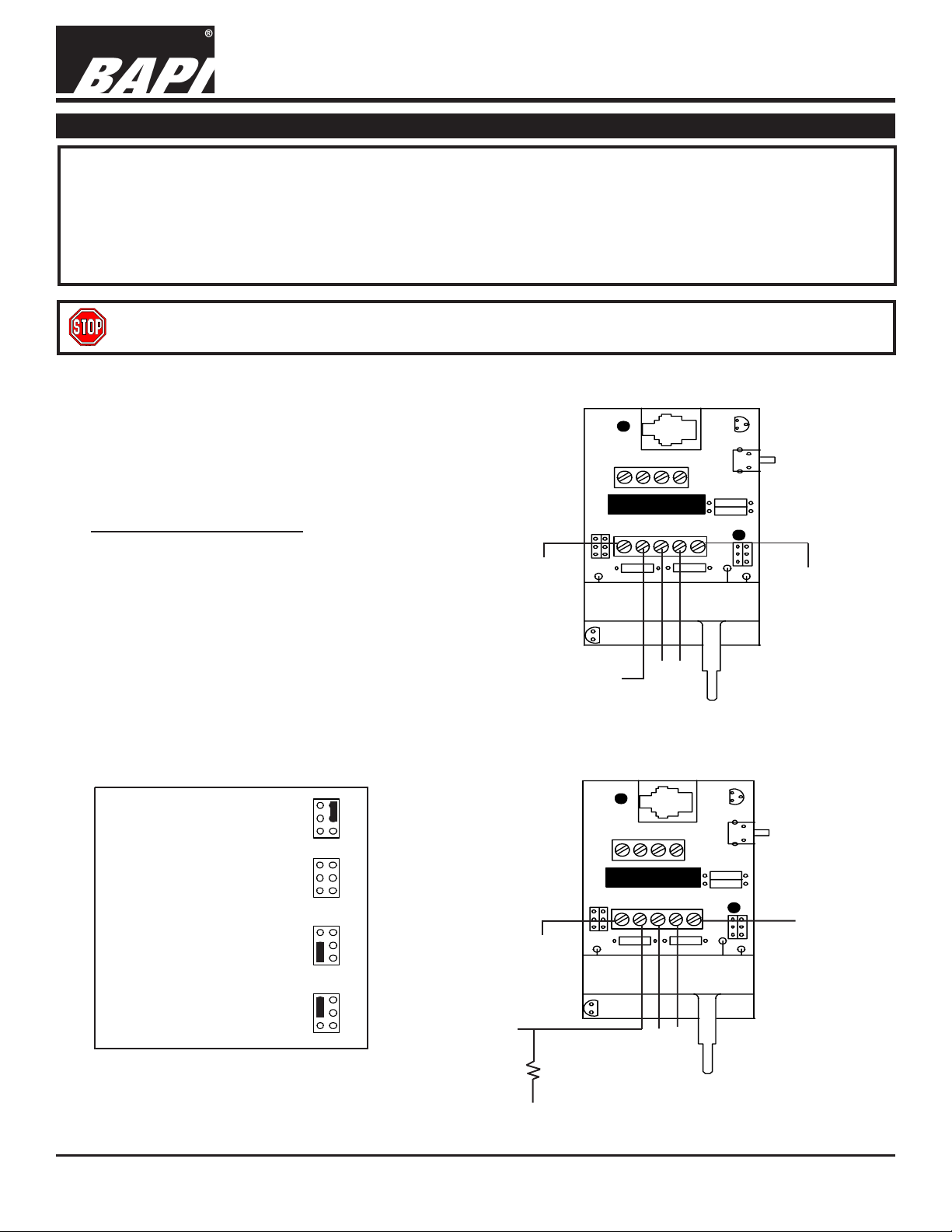
1. For 592-10K units, sensor is measured at Sen +Gnd.
For 592 units, a 10K ohm 0.1% resistor must be
installed between the controller input and ground.
2. Override (O/R) and Setpoint (Set) are with reference
to Gnd.
TERMINAL CONNECTIONS
V+ = +7 to 30 VDC input
Sen = Sensor out
O/R = Override
Set = Setpoint output, voltage(see
product label for span)
Gnd = Common for O/R and Set
TB1 = Comm jack power (+5 Volts)
TB2 = Comm +
TB3 = Comm TB4 = Comm Jack Ground
Jumper configurations (both units)
J1: Selects AD 592 sensor
J2: Override as seperate input
J2: Override//setpoint
5 to 30VDC
Sensor
Output
(10mV/°K)
5 to 30VDC
592-10K Room Sensor
TB1
J1
1
+V
Sen
4
O/R
Set
Gnd
(Override)
(Setpoint)
592 Room Sensor
TB1
O/R
Set
4
Gnd
J2
1
J1
+V
Sen
J2
Ground
Ground
J2: Override//sensor
Sensor Output
(10mV/°K)
10K ohm 0.1%
resistor
Ground
Specifications subject to change without notice.
(Setpoint)
(Override)
1
Page 2
592/592-10K Room/Setpoint/Override/Comm Jack
8586_ins_592_rm_set_or_cj
Offsetting
All BA592 sensors will have the following information provided on a label:
T ermination and Troubleshooting
11/9/04
rev.
Thermistor Reading_______
The actual temperature reading
according to a thermometer that
is certified traceable to
recognized standards by the
National Institute of Standards and
Technology (NIST).
To correct the Sensor Reading, simply add the offset value to the sensor reading so that it equals the thermometer reading.
e.g. Therm Reading 74.6 Sensor Reading 73.0 Offset +1.6
Correction: Add (+1.6) °F to the sensor for an accurate reading: 73 + 1.6 = 74.6°F
e.g. Therm Reading 75.4 Sensor Reading 77.2 Offset -1.8
Correction: Add (-1.6) °F to the sensor for an accurate reading: 77.2 + (-1.8) = 75.4°F
Sensor Reading ______
The temperature reading according
to the AD592 sensor, using the
output in either uA or V and
converting the output to a
Fahrenheit temperature.
Troubleshooting
Offset_______
The difference between the
Thermometer Reading and the
Sensor Reading.
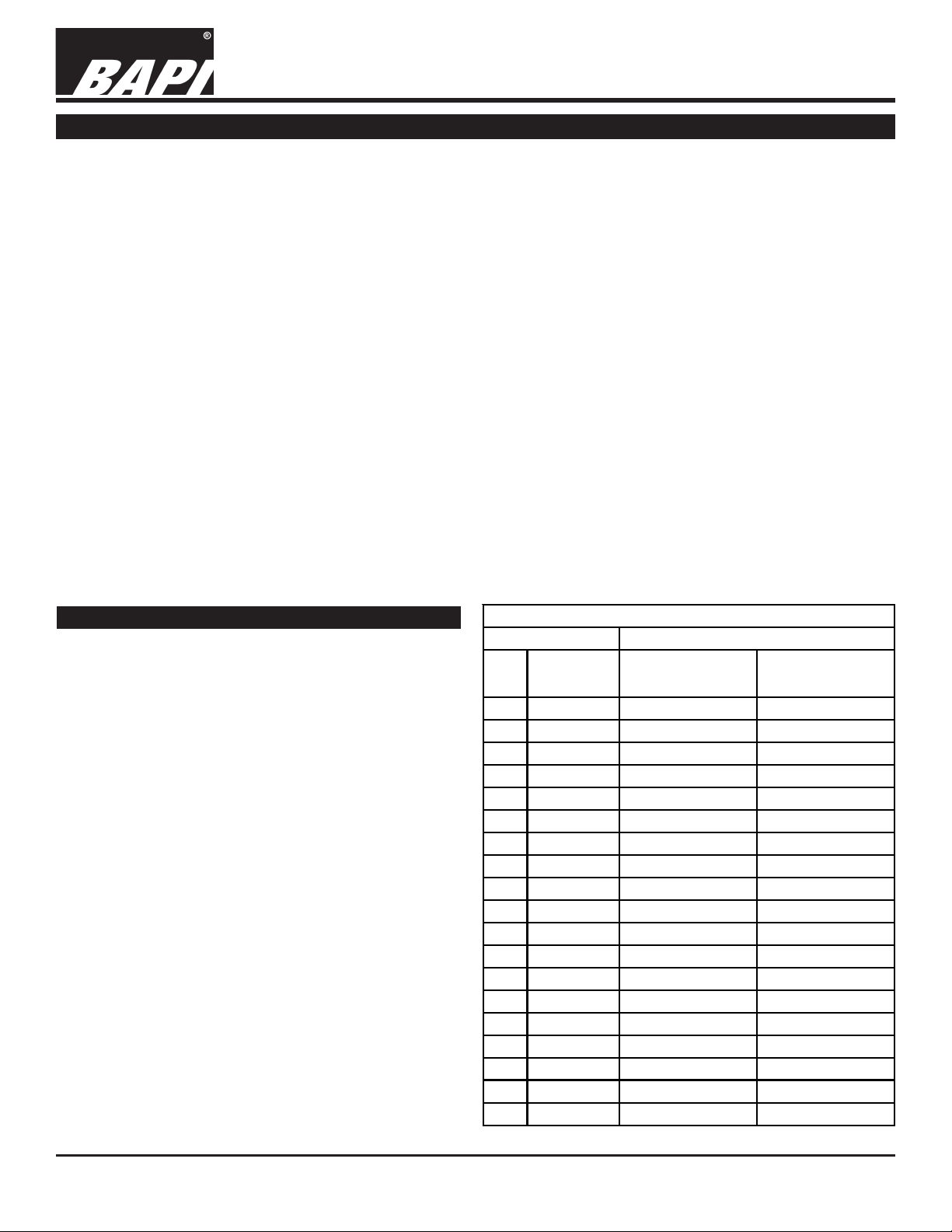
592 Output Table
Temperature 592 Semiconductor
If the unit you installed does not respond properly,
please go through the following steps:
°F °C
Output Current uAOutput Voltage
across 10KΩ
50 10.00 283.2 2.832
1. Set your meter to the V setting.
2. Measure the voltage between the “Sen” and
“GND.” See diagrams above in the Termination
section.
3. Compare the voltage reading to the voltage listed
in the output table.
4. If the sensor reads significantly lower or 0, then
your sensor may be shorted.
5. If the sensor reads significantly higher then the
sensor may be open.
6. If the sensor reads properly, verify that the
controller is operating correctly.
60 15.56 288.8 2.888
62 16.67 289.9 2.899
64 17.78 291.0 2.910
66 18.89 292.1 2.921
68 20.00 293.2 2.932
70 21.11 294.3 2.943
72 22.22 295.4 2.954
74 23.33 296.5 2.965
76 24.44 297.6 2.976
77 25.00 298.2 2.982
78 25.56 298.8 2.988
80 26.67 299.9 2.999
82 27.78 301.0 3.010
84 28.89 302.1 3.021
86 30.00 303.2 3.032
88 31.11 304.3 3.043
90 32.22 305.4 3.054
100 37.78 311.0 3.110
Specifications subject to change without notice.
2
Page 3

8586_ins_592_rm_set_or_cj
Mounting
Fig. 2
592/592-10K Room/Setpoint/Override/Comm Jack
T ermination and Troubleshooting
11/9/04
rev.
Mounting hardware is provided for both junction box and drywall installation (junction box installation shown).
Junction Box
1. Pull the wire through the wall and out of the junction box, leaving about six inches free.
2. Pull the wire through the hole in the base plate.
3. Secure the plate to the box using the #6-32 x 1/2 inch mounting screw provided.
4. Terminate the unit according to the guidelines in Termination on page 1.
5. Attach Cover by latching it to the top of the base, rotating the cover down and snapping it into place.
6. Secure the cover by backing out the lock-down screws using a 1/16" allen wrench until they are flush with the bottom
of the cover.
Drywall Mounting
1. Place the base plate against the wall where you want to mount the sensor.
2. Using a pencil mark out the two mounting holes and the area where the wires will come through the wall.
3. Drill two 3/16" holes in the center of each marked mounting hole. Insert a drywall anchor into each hole.
4. Drill one 1/2" hole in the middle of the marked wiring area.
5. Pull the wire through the wall and out of the 1/2" hole, leaving about six inches free.
6. Pull the wire through the hole in the base plate.
7. Secure the base to the drywall anchors using the #6 x 1 inch mounting screws provided.
8. Terminate the unit according to the guidelines in Termination on page 1.
9. Attach cover by latching it to the top of the base, rotating the cover down and snapping it into place.
10. Secure the cover by backing out the lock-down screws using a 1/16" allen wrench until they are flush with the bottom
of the cover.
NOTE
In a wall-mount application, the wall temperature and the temperature of the air within the wall cavity can cause erroneous
readings. The mixing of room air and air from within the wall cavity can lead to condensation, erroneous readings and
premature failure of the sensor.
T o prevent these conditions, seal the conduit leading to the junction box and use BAPI’ s adhesive backed, foam insulating
pad centered over the hole(order part number BA/FOAMBACK).
Specifications subject to change without notice.
3
Page 4

The BAPI Family of Sensors for HVAC/R
Temperature & Humidity Sensors
Temperature or Humidity Alone or Combination Sensors
Room Units • Wall Plate Units • Duct Units • Immersion Units
Thermowells • Strap Units • Outside Air Units
Room Units
Wall Plate Units
Outside
Air Units
Zone Pressure Sensors
Differential Pressure
Transmitter
Differential Pressure
Transmitter with
Air Quality Sensors
Display
Duct Units
Duct Averaging Units
Immersion Units
Accessories
Power Supplies & Voltage Converters
Sealant Filled Connectors
Field Mounting Kits & More
Room Mount
Air Quality Sensor
Duct Mount
Air Quality Sensor
VC75 Voltage
Converter
4
 Loading...