


A151 Benchtop Conductivity Meter
Instruction Manual
BANTE INSTRUMENTS CO., LTD

A151 Benchtop Conductivity Meter
1
Introduction
Thank you for selecting the A151 benchtop conductivity meter. This manual provides a step-by-step guide to help you operate the meter, please carefully
read the following instructions before use.
Unpacking
Before unpacking, ensure that the current work environment meets following conditions.
• Relative humidity is less than 80 %.
• Ambient temperature is greater than 0°C and less than 60°C.
• No potential electromagnetic interference.
The following list describes the standard components of the meter. After the unpacking, please check all components are complete. If any are damaged or
missing, please contact nearest distributor.
A151 Conductivity Meter
Electrode Holder
Conductivity Standard Solutions
CON-1 Conductivity Electrode
TP-10K Temperature Probe
DC12V Power Adapter

A151 Benchtop Conductivity Meter
2
Keypad
The A151 meter has a succinct membrane keypad, names and symbols describe the each function key controls.
KEY
FUNCTION
• Switches the meter ON/OFF.
• Exits the calibration or setting and returns to measurement.
• Selects the measurement mode.
• Sets the temperature of sample (Press and hold the key for 3 seconds).
• Starts calibration.
• Enters the setup menu (Press and hold the key for 3 seconds).
• Locks the measured value.
• Resume measuring.
• Sends data to a printer or computer.
• Stores current reading to memory.
• Increase value or scroll up through the menu item.
• Views the calibration report or data logs.
• Decrease value or scroll down through the menu item.
• Confirms the calibration, settings or displayed options.
Connectors
NO.
CONNECTOR
DESCRIPTION
1
EC
Used for connecting the 4-pole conductivity electrode
2
EC/DO
Used for connecting the 2-pole conductivity electrode
3
°C
Used for connecting the temperature probe
4
USB
Used for connecting the computer or printer
5 Used for connecting the power adapter

A151 Benchtop Conductivity Meter
3
Installing the Electrode Holder
Take out the electrode holder from the packaging. Turn the meter over. Align the base plate of the electrode holder with the circular holes on the meter.
Moderately tighten two screws.
Adjustment of electrode arm
After installation, if the electrode arm automatically rises or falls, you need to adjust the screw until arm locate at any position.
1. Remove the plastic cover from the electrode arm.
2. Use the screwdriver to tighten the screw moderately.
3. Insert the plastic cover to previous position. Installation is completed.
Connecting the Electorde
1. Take out the conductivity electrode from the packaging. Follow the steps below to place the electrode into left or right side of the electrode arm.
1. Insert the electrode
2. Hook up the cable
3. Hook up the cable

A151 Benchtop Conductivity Meter
4
2. Insert the 6-pin connector into the connector socket labeled EC/DO. After the connection is completed, DO NOT pull on the cable. Always make sure
that the connector is clean and dry.
Connecting the Temperature Probe
1. Place the temperature probe into the circular hole of the electrode arm.
2. Insert the phone plug to the connector socket labeled °C. Ensure the connector is fully seated.
Connecting the Power Adapter
1. Before plugging in the power adapter, ensure that its voltage matches the local main voltage.
2. Insert the connector to the power socket. The meter is now ready for use.

A151 Benchtop Conductivity Meter
5
Switching the Meter On and Off
• Press and hold the key to switch on the meter, the display shows the measured values.
• Press and hold the key for 3 seconds, the meter will switch off.
To enable the Auto-Power Off feature, please refer to chapter SETUP MENU.
Setup Menu
The A151 conductivity meter contains an integrated setup menu that is used to customize the displayed option to meet measurement requirements. The
following table describes the functions of the menu items.
MENU
OPTIONS
DESCRIPTION
DEFAULT
Sample ID
0000 to 9999
Set the sample ID to associate readings with the data log.
0000
Cell Constant
2-pole electrode (K=0.1)
Set the cell constant to match connected electrode.
2-pole
electrode
(K=1)
2-pole electrode (K=1)
2-pole electrode (K=10)
4-pole electrode
Calibration Points
1 to 3 points
Set the number of calibration points.
3 points
Temperature Coefficient
Linear (Range: 0.0 to 10.0%/°C)
Set the temperature compensation type and coefficient.
Linear
(2.1%/°C)
Non-linear
Pure Water Coefficient
Enable
When the option is enabled, pure water coefficient will be
applied automatically for ultra-pure water measurements.
Disable
Disable
Reference Temperature
20°C
Set the normalization temperature for conductivity
measurement and calibration.
25°C
25°C
TDS Factor
Range: 0.01 to 1.00
Set the default TDS conversion factor.
0.50
Alarm Limits
Enable
Set the high and low limit values to activate alarm
(Range: 0 to 999).
Disable
Disable
Calibration Due
Enable
Set the calibration interval to activate alarm (1 to 31 days).
Disable
Disable
Temperature Unit
°C
Set the default temperature unit.
°C
°F
Stability Criteria
Standard
Set when a measurement is recognized as stable.
Standard
High-accuracy
Auto-Read
Enable
When the option is enabled, the meter will automatically
sense a stable reading and lock the measurements.
Disable
Disable
Auto-Power Off
Enable
When the option is enabled, the meter will automatically
switch off if no key is pressed within 3 hours.
Disable
Disable
Date and Time
Year-month-day, hour-minutes
Set the current date and time.

A151 Benchtop Conductivity Meter
6
Interval Readings
Off
When the option is enabled, the meter will automatically
send the measured data to the computer or printer.
Off
10 seconds
30 seconds
60 seconds
10 minutes
30 minutes
Password
Enable
Set the password protection for calibration and settings.
Disable
Disable
Brightness
Low, Mid, High
Set the brightness level of the backlight.
Mid
Clear Stored Data
Enable
Delete all stored readings in the memory.
Disable
Disable
Factory Reset
Enable
Reset the meter to factory default settings.
Disable
Disable
Setting the default option
1. In the measurement mode, press and hold the key for 3 seconds to enter the setup menu.
2. Press the or key to select the menu item.
3. Press the Enter key, the cursor changes to highlight.
4. Press the or key to select the desired option.
5. Press the Enter key to confirm, the meter returns to the measurement mode. Setting is completed.
Setting the default parameter
The meter provides two methods for parameter settings.
• Press the or key to modify the value, press the Enter key to confirm.
• If the cursor appears below the first digit, press the or key to set the value, press the Enter key to confirm and move to the next digit. Repeat
the steps above until the meter returns to the measurement mode. Setting is completed.
During the setting process, press the or key once, the setting value will increase or decrease gradually. Press and hold the or key, the
setting value will increase or decrease quickly.
Setup example - alarm limits
1. In the measurement mode, press and hold the key for 3 seconds to enter the setup menu.
2. Press the or key to select the “Alarm Limits”.
3. Press the Enter key, the cursor changes to highlight.
4. Press the or key to select the measurement unit, press the Enter key to confirm.
5. Press the or key to set the high alarm value, press the Enter key to confirm.
6. Press the or key to select the measurement unit, press the Enter key to confirm.
7. Press the or key to set the low alarm value, press the Enter key to return to the measurement mode.

A151 Benchtop Conductivity Meter
7
Temperature Coefficient
The A151 conductivity meter contains two temperature correction methods. The linear temperature correction is appropriate for most samples. If the current
sample is belong to the natural water (e.g., natural ground, well, or surface waters), using the non-linear correction is necessary. Note: non-linear correction
can only be performed at temperature range from 0°C to 36°C. If the temperature value is out of above range, the meter will show a warning.
To calculate the temperature coefficient, please refer to addendum “How to calculate the temperature coefficient”.
Pure Water Coefficient
The pure water coefficient is used to correct the samples with a conductivity of less than 5µ S/cm. If enabled, the meter will be automatically calculated and
applied coefficient for ultra-pure water measurements.
A151 Benchtop Conductivity Meter
8
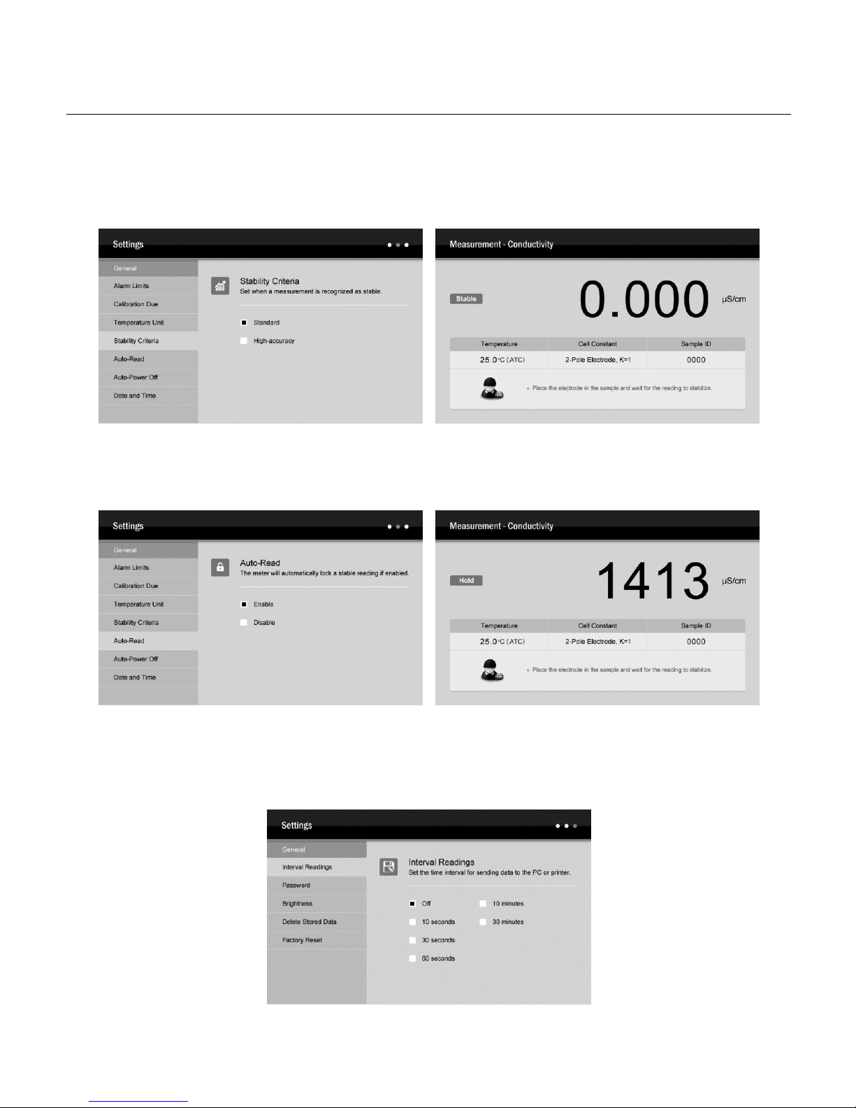
Stability Criteria
The Stability setting allows the user to set when a measurement is recognized as stable by the meter. When the Standard option is enabled, the Stable icon
will quickly appear on the display. When the High-accuracy option is enabled, the icon will take longer to appear, but guarantees high accuracy of the
measurement.
Auto-Read
The Auto-Read feature is used to lock a measurement endpoint. If enabled, the meter will automatically sense a stable reading and lock the measurements.
The HOLD icon appears on the display. Press the Meas key, the meter resumes measuring.
Interval Readings
The Interval Readings is capable of recording the measurements at the predefined time intervals. If enabled, the meter will continue to send measured data
to the printer or computer until the measurement mode is exited. You are able to use the DAS software for receiving the data or viewing the real-time graph.
For more details, please refer to chapter COMMUNICATION.

A151 Benchtop Conductivity Meter
9
Password
The password protection is used to prevent the unauthorized calibration and settings. If enabled, the user must enter the 4-digit password to access the
calibration or setup menu. If the setting value is 0000, the password protection will invalid.
Unlock or Reset the password
Press and hold the key in the measurement mode, the password input window immediately shows on the display and wait for entering the correct digits.
Press the or key to input the password, press the Enter key to confirm. Once you have successfully entered the setup menu, selecting the “Disable”.
The password will be removed.
Factory Reset
The Factory Reset will restore the meter back to factory default settings. If enabled, all of the calibration data and selected options/parameters will be lost
or reset, the meter must be recalibrated. During the setting process, when the display shows “Are you sure you want to reset the meter ?”, press the Enter
key, the meter will immediately restore the factory settings, press the ESC key to cancel.

A151 Benchtop Conductivity Meter
10
Prior to Use
Soak the conductivity electrode for a few minutes in tap water to remove dirt and oil stains on the electrode.
Temperature Compensation
For better accuracy, we recommend the use of either a sensor with a built-in or a separate temperature probe for the calibration or measurement.
Automatic Temperature Compensation
Connect the temperature probe to the meter (Refer to page 4 “Connecting the Temperature Probe”). The ATC icon immediately appears on the display, the
meter is now switched to the automatic temperature compensation mode.
Manual Temperature Compensation
If the meter does not detect a temperature probe, the MTC icon will show on the display indicating that the meter is switched to the manual temperature
compensation mode. To set the temperature value, follow the steps below.
1. Press and hold the
o
C key for 3 seconds to enter the temperature setting mode.
2. Press the or key to modify the temperature value.
3. Press the Enter key to confirm, the meter returns to the measurement mode. Setting is completed.
Press the or key once, the setting value will increase or decrease by 0.1. Press and hold the or key, the setting value will increase or
decrease by 1.

A151 Benchtop Conductivity Meter
11
Selecting the Conductivity Electrode
The A151 conductivity meter is capable of using the 3 types of 2-pole conductivity electrodes. Prior to the calibration and measurement, you need to select
the different sensors as per your sample concentration. The table below shows available electrodes and its effective measuring ranges.
CONDUCTIVITY ELECTRODE
MEASURING RANGES
CELL CONSTANT
CON-0.1
0.1~100µ S/cm
K=0.1
CON-1
10µ S/cm~10mS/cm
K=1
CON-10
100µ S/cm~200mS/cm
K=10
If the 4-pole conductivity electrode is selected, its best measurement range is 100µ S/cm to 200mS/cm.
Conductivity Calibration
The meter allows 1 to 3 points calibration in the conductivity mode. To ensure higher accuracy, we recommend that you perform 3 points calibration or select
a standard value close to the sample value you are measuring. The meter will automatically detect these conductivity standard solutions and prompt the
user to calibrate the meter. When the calibration is completed, all new calibration values will automatically override existing data.
The following table shows acceptable conductivity range of standard solution for each measuring range.
MEASURING RANGE
CALIBRATION SOLUTION RANGE
DEFAULT
0~20µ S/cm
7~17µ S/cm
10µ S/cm
20~200µ S/cm
70~170µ S/cm
84µ S/cm
200~2000µ S/cm
700~1700µ S/cm
1413µ S/cm
2~20mS/cm
7~17mS/cm
12.88mS/cm
20~200mS/cm
70~170mS/cm
111.8mS/cm
Single point calibration
1.1 Ensure that the meter is in the conductivity measurement mode and you have selected 1 point calibration in the setup menu.
1.2 Rinse the conductivity electrode with distilled water, then rinse with a small amount of standard solution.
1.3 Press the Cal key, the display shows “Calibration Point 1” and waits for recognizing the standard solution.

A151 Benchtop Conductivity Meter
12
1.4 Place the conductivity electrode into the standard solution, the meter automatically shows current calibration standard (e.g., 1413µ S/cm).
1.5 If necessary, press the or key to modify the calibration value.
1.6 Press the Enter key, the Calibrating.. icon shows on the display.
1.7 Wait for the reading to stabilize, the meter automatically shows “Calibration is completed” and returns to the measurement mode.

A151 Benchtop Conductivity Meter
13
Multi-point calibration
2.1 Ensure that you have selected 2 or 3 points calibration in the setup menu.
2.2 Repeat steps 1.2 to 1.6 above. When the first calibration point is completed, the display will show “Calibration Point 2”. The meter prompts you to
continue with second point calibration.
2.3 Rinse the conductivity electrode with distilled water. Place the electrode into the next standard solution, the meter automatically shows current
calibration standard (e.g., 12.88mS/cm).
2.4 If necessary, press the or key to modify the calibration value.
2.5 Press the Enter key, the meter begins the calibration.

A151 Benchtop Conductivity Meter
14
2.6 Wait for the reading to stabilize, the display will show “Calibration Point 3”. The meter prompts you to continue with third point calibration.
2.7 Repeat the steps 2.3 to 2.5 above until the meter returns to the measurement mode. Calibration is completed.
• Performing the conductivity calibration will simultaneously calibrate the corresponding TDS, salinity and resistivity.
• If you want to exit the calibration, press the ESC key, the meter will immediately return to the measurement mode.
Temperature Calibration
During the measurement process, if the temperature reading displayed differs from that of an accurate thermometer, the meter needs to be calibrated.
1. Connect the temperature probe to the meter and place into a solution with a known accurate temperature.
2. Press and hold the
o
C key for 3 seconds to enter the calibration mode.
3. Press the or key to set the temperature value.
4. Press the Enter key, the meter returns to the measurement mode. Calibrating is completed.

A151 Benchtop Conductivity Meter
15
Calibration Report
The A151 conductivity meter provides detailed report for the conductivity calibration.
1. Press the MR key in the measurement mode, the meter shows the data log options.
2. Press the or key to select the “Calibration Report”.
3. Press the Enter key, the display shows the updated calibration information.
4. Press the ESC key, the meter returns to the measurement mode.
Conductivity/TDS/Salinity/Resistivity Measurement
1. Press the Mode key in measurement mode and the or key to select desired option, press the Enter key to confirm.
2. Rinse the conductivity electrode thoroughly with distilled water.
3. Place the electrode into the sample solution, stir the electrode gently.
4. Record the measured value when the reading is stable.

A151 Benchtop Conductivity Meter
16
Storing and Recalling Data from Memory
The A151 conductivity meter are capable of storing and recalling up to 1000 data sets.
Storing a measurement result
During the measurement process, press the MI key to store the measured value, the meter will show a reminder as follow.
Recalling from memory
1.1 Press the MR key in the measurement mode, the meter shows the data log options.
1.2 Press the or key to select the “Stored Data”.
1.3 Press the Enter key, the display shows the data list.
1.4 Press the ESC key, the meter returns to the measurement mode.

A151 Benchtop Conductivity Meter
17
Clearing the memory
If the memory is full, the meter will automatically show a reminder and wait for user to delete all stored readings.
WARNING: once the data are deleted that can not be recovered.
2.1 In the measurement mode, press and hold the key for 3 seconds to enter the setup menu.
2.2 Press the or key to select the “Clear Stored Data”.
2.3 Press the Enter key, the cursor change to highlight.
2.4 Press the key to select the “Enable”.
2.5 Press the Enter key, the meter shows a warning “Are you sure you want to delete all date logs ?”
2.6 Press the Enter key to confirm or the ESC key to cancel. The meter returns to the measurement mode.
A151 Benchtop Conductivity Meter
18
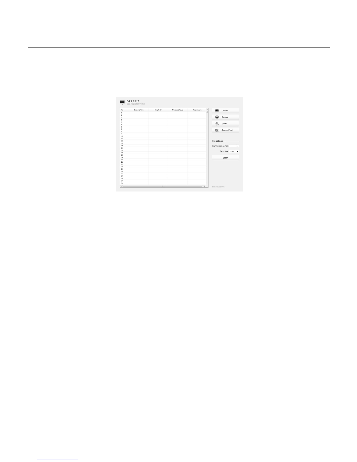
Communication
Bante Instruments provides a Data Acquisition System that can be used to transfer data, receive the measuring values or import the data to Excel. You are
able to download this software from our official website at www.bante-china.com. Before installation, ensure that Windows 7/8/10 operating system has
been installed on your computer.
Receiving data
1. Connect the USB cable and data converter to the meter and computer.
2. Click the DAS_A_Series icon on computer, the system will automatically scan an available communication port and show the message box “Found a
port on your computer”.
3. Click the OK button, the application starts.
4. Click the Connect button, the screen shows “Port is connected” indicating that the communication between the meter and the computer has been
established.
5. Click the OK button to confirm.
6. Click the Receive button, the stored data automatically transfer to computer.
Interval recording
This function is used to record the measuring value within the specify time period. The setting method refers to page 6 “Setting the Default Options”. Note:
• The first data need 1 minute to be shown on screen.
• Do not press any key on meter during the Interval Recording mode, it will cause the communication interruption.
Graph mode
This function helps user to view variations of the measured value continuously. Click the Graph button, the screen immediately shows the curve graph.
Click the X button to quit.
Create the excel file
When the data transfer is completed, click the Save as Excel button, the measured values in the data sheet will automatically convert to Excel file.
WARNING: Once the software is closed, all received data will be lost and can not be recovered.

A151 Benchtop Conductivity Meter
19
Conductivity Electrode Care and Maintenance
• DO NOT touch the measurement area of electrode and always make sure that is clean.
• If there is a build-up of solids inside the measurement area, these should be removed very carefully with a cotton bud soaked in solvent, taking care
not to touch the metal parts of the inner cell. After the solids are removed, the electrode must be recalibrated.
Specifications
Conductivity
Model
A151
Range
0.01~20.00, 200.0, 2000µ S/cm, 20.00, 200.0mS/cm
Accuracy
± 0.5% F.S
Resolution
0.001, 0.01, 0.1, 1
Calibration Points
1 to 5 points
Calibration Solutions
10µ S/cm, 84µ S/cm,1413µ S/cm,12.88mS/cm,111.8mS/cm
TDS
Range
0.00mg/L~100.0g/L (Max. 200g/L)
Accuracy
± 1% F.S
TDS Factor
0.01~1.00 (Default 0.5)
Salinity
Range
0.00~80.00ppt, 0.00~42.00psu, 0.00~8.00%
Accuracy
± 1% F.S
Measurement Modes
Practical Salinity (psu), Natural Seawater (ppt) or %
Resistivity
Range
0.00~30.00MΩ
Accuracy
± 1% F.S
Resolution
0.01, 0.1, 1
Temperature
Range
0~105° C, 32~221°F
Accuracy
± 0.5° C
Calibration Points
1 point
General
Temperature Compensation
0~100° C, 32~212°F, Manual or Automatic
Temperature Coefficient
Linear, Non-linear and Pure water compensation
Normalization Temperature
20° C or 25° C
Cell Constant
2-pole electrodes (K=0.1, 1, 10) or 4-pole electrode
Memory
Stores up to 1000 data sets
Output
USB Communication Interface
Power Requirements
DC12V/2A, using AC adapters, 220VAC/50Hz
Dimensions
240 (L) × 220 (W) × 80 (H)mm
Weight
1.7kg

A151 Benchtop Conductivity Meter
20
Addendum 1: Preparation of Conductivity Standard Solutions
Place AR potassium chloride reagent in a 50ml beaker and dry in an oven for 3 to 5 hours at 105° C, then cool to room temperature in desiccator.
CALIBRATION SOLUTIONS
REAGENT
84µ S/cm
Accurately weigh out 42.35mg of KCL and dissolve in 1 litre deionised water.
1413µ S/cm
Accurately weigh out 745.9mg of KCL and dissolve in 1 litre deionised water.
12.88mS/cm
Accurately weigh out 7.45g of KCL and dissolve in 1 litre deionised water.
111.8mS/cm
Accurately weigh out 74.5g of KC, and dissolve in 1 litre deionised water.
Stir the solution until the reagent has thoroughly mixed. Preparation is completed.
Addendum 2: How to calculate the temperature coefficient
To determine the temperature coefficient of sample solution use the formula below:
Tc = × 100%
Where:
TC = Temperature coefficient
C
TA
= Conductivity at Temperature A
C
TB
= Conductivity at Temperature B
TA = Temperature A
TB = Temperature B
1. Press and hold the
o
C key for 3 seconds to enter the temperature setting.
2. Press the or key to set the temperature to 25 ° C.
3. Place the electrode into the sample solution A and record the temperature value TA and conductivity value CTA.
4. Condition the sample solution and electrode to a temperature that is about 5 ° C to 10 ° C different from TA. Record the temperature value TB and
conductivity value CTB.
5. Calculate the temperature coefficient according to the formula above.
Addendum 3: How to calculate the TDS conversion factor
To determine the TDS conversion factor use the formula below:
Factor =
Where:
Actual TDS: value from the high purity water and precisely weighed NaCl or KCL reagent.
Actual Conductivity: the meter measured conductivity value.
For example: dissolve 64g of potassium chloride reagent in 1 litre distilled water. If its conductivity value is 100mS/cm, then TDS conversion factor is 0.64.
CTB-CTA
CTA(TB-25)-CTB(TA-25)
Actual TDS
Actual Conductivity @ 25 ° C

Hazardous Substance Statement
Bante Instruments is committed to the reduction and eventual elimination of all hazardous substances in both the manufacturing process and finished
products we supply. We have an active manufacturing and procurement program to minimize and eliminate the use of harmful heavy metals such as
cadmium, lead, mercury and the like. New technologies and design parameters are also promoting these efforts and we expect to have little or no such
materials in our product in the coming years. We welcome our customer suggestions on how to speed up these efforts.
Warranty
The warranty period for meter is one year from the date of shipment. Above warranty does not cover the sensor and calibration solutions. Out of warranty
products will be repaired on a charged basis. The warranty on your meter shall not apply to defects resulting from:
• Improper or inadequate maintenance by customer.
• Unauthorized modification or misuse.
• Operation outside of the environment specifications of the products.
For more information, please contact the nearest authorized distributor.
BANTE INSTRUMENTS CO., LTD
E-mail: banteinstruments@yahoo.com
Phone: +8621-6404-1598
Website: www.bante-china.com
The information in this document is subject to change without notice. Copyright © Bante Instruments, 2018. All rights reserved.
 Loading...