

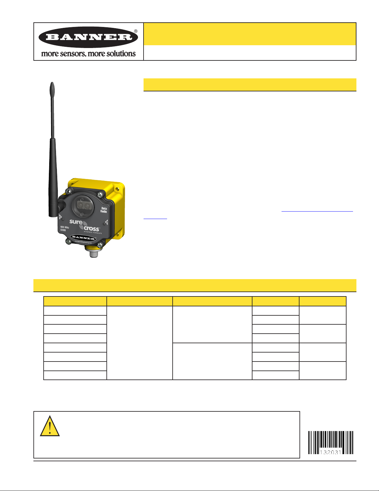
SureCross™ 1 Watt Data Radio
SureCross™ 1 Watt Data Radio
Features
Data radios may be used to expand a Modbus network or avoid obstacles in the path of
the radio signals.
Wireless industrial device to extend the range of a Modbus network
•
+10 to 30V dc power input
•
Data routing controlled by Modbus slave IDs
•
Radio networks use unique network IDs
•
Frequency Hopping Spread Spectrum (FHSS) technology and Time Division
•
Multiple Access (TDMA) control architecture combine to ensure reliable data
delivery within the unlicensed Industrial, Scientific, and Medical (ISM) bands
Transceivers provide two-way communication between radios
•
For additional information and a complete list of accessories, including FCC approved
antennas, please refer to Banner Engineering’s website, www.bannerengineering.com/
surecross.
Models
Model Power Frequency Master/Slave Serial Type
DX87M9S2
DX87S9S42 Slave
DX87M9S4 Master
DX87S9S4 Slave
DX87M2S2
DX87S2S42 Slave
DX87M2S4 Master
DX87S2S4 Slave
WARNING…
Never use these products for personnel protection. Doing so could lead to serious injury or death.
These products do NOT include the self-checking redundant circuitry necessary to allow their use in personnel safety
applications. A failure or malfunction can cause either an energized or de-energized product output condition. Consult your
current Banner Safety Products catalog for safety products that meet OSHA, ANSI, and IEC standards for personnel protection.
Printed in USA 10/07 P/N 132031
Not to be used for personnel protection
10 to 30V dc
900 MHz ISM Band
2.4 GHz ISM Band
Master
Master
RS232
RS485
RS232
RS485
SureCross™ 1 Watt Data Radio
NID A
NID A
NID A
NID 1
NID 1
NID 1
NID 2
NID 2
NID 2
Modbus
Master
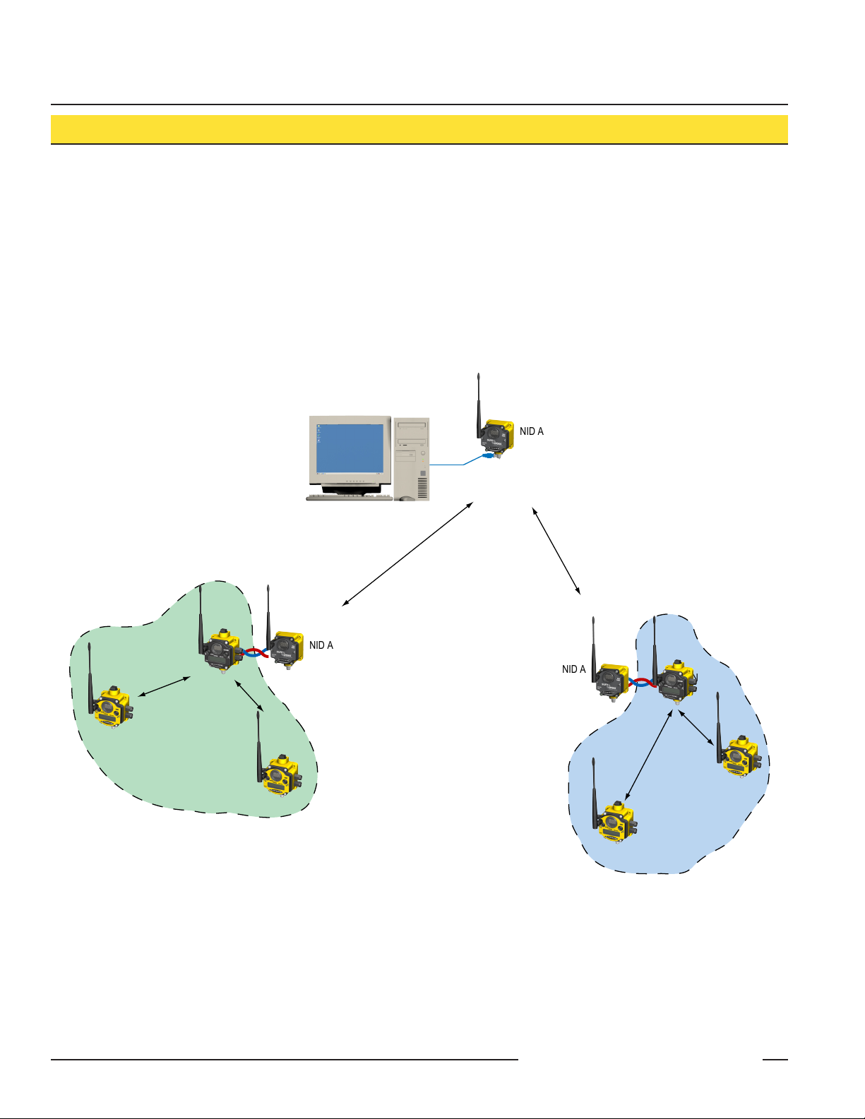
Overview
Serial radios connect a Modbus control system to one or more DX80 Gateway devices acting as Modbus slaves. The data radios do not
use addressing, error checking, or acknowledgement in the radio packets. Instead, the data stream appearing on the serial input of one
radio within the network is reproduced on the serial outputs of all other radios in the same network. Addressing and error connection
occur at the application layer. The system operates as it would in a hardwired Modbus multi-drop serial network.
All deterministic properties of the DX80 star networks are preserved. If a data radio linkage drops multiple packets, the target DX80
Gateway reacts as if the serial line was cut, driving all outputs in the local TDMA system to the predefined state. The data radio links are
collision free because the master control system uses polling to initiate all data exchanges so all data radio packets originate from the
same place.
Each DX80 TDMA cluster is inherently collision free. The only potential collisions occur when hardwired DX80 Gateway devices and
data radios are collocated. Fortunately, the application layer (Modbus) retries the packet until it succeeds. Using 2.4 GHz radios in the
local TDMA links and 900 MHz in the data radio links (or vice versa) also minimizes data collisions.
2 P/N 132031
Banner Engineering Corp. • Minneapolis, MN U.S.A.
www.bannerengineering.com • Tel: 763.544.3164
SureCross™ 1 Watt Data Radio
NID A
NID A
NID A
NID 1
NID 1
NID 1
NID 2
NID 2
NID 2
Modbus
Master
NID B
NID B
NID 3
NID 3
NID 3
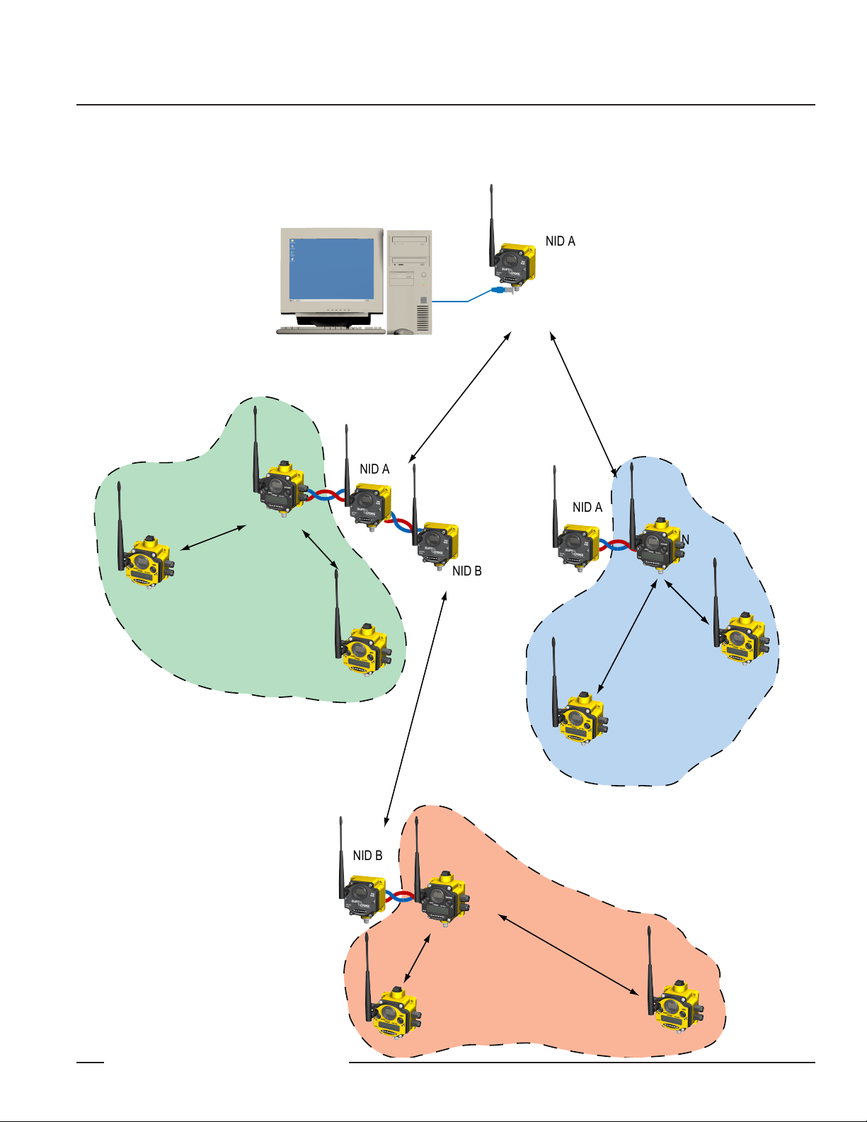
This concept can be expanded indefinitely by chaining independent data radio connections through the serial interface. Very large
networks can be created without complex network addressing. Modbus networks can be extended almost without limit while still
maintaining the determinism and latency of the underlying TDMA networks.
Banner Engineering Corp. • Minneapolis, MN U.S.A.
www.bannerengineering.com • Tel: 763.544.3164
P/N 132031 3

SureCross™ 1 Watt Data Radio
Hookup Diagrams
5-pin M12 Euro Hookup
Color No. Description
Brown 1 10 to 30V dc Input
White 2 RS485 / D1 / B /+
Blue 3 dc common
Black 4 RS485 / D0 / A / -
Gray 5 Comms Gnd
Note: Terminal block GND = dc common
Configuration
Network and Device ID
Since the data stream appearing on the serial input of one radio
within the network is reproduced on the serial outputs of all other
radios in the same network, the only configuration necessary is to
set up the network ID and device ID.
To setup the data radio:
Set each radio in the same network to the same network ID
1.
(NID).
Set the device ID of one radio in each NID network to zero.
2.
This radio acts as the time keeper for the radio network and
can be any radio in the network.
Set the device IDs for the other radios within the same
3.
network to any device number other than zero. Except for
the one radio set to device ID zero, the other device ID
settings are ignored by the radio network.
Switches
Use the switches on the board to set the baud rate and parity.
Baud Rate Switches Parity Switches
1 2 3 4
Off Off 19200 (default)* Off Off None (default)*
On Off 9600 On Off Odd
Off On 38400 Off On Even
On On 19200 On On None
Network ID
Device ID
* Default position shown
4 P/N 132031
Banner Engineering Corp. • Minneapolis, MN U.S.A.
www.bannerengineering.com • Tel: 763.544.3164

SureCross™ 1 Watt Data Radio
Banner Engineering Corp. • Minneapolis, MN U.S.A.
www.bannerengineering.com • Tel: 763.544.3164
P/N 132031 5

SureCross™ 1 Watt Data Radio
FCC Certification - 900 MHz, 1 Watt Radio
FCC Certification
The DX80 Module complies with Part 15 of the FCC rules and regulations.
FCC ID: UE3RM1809 This device complies with Part 15 of the FCC Rules. Operation is subject to the following two conditions: (1) this
device may not cause harmful interference, and (2) this device must accept any interference received, including interference that may
cause undesired operation.
FCC Notices
IMPORTANT: The DX80 Modules have been certified by the FCC for use with other products without any further certification (as per
FCC section 2.1091). Changes or modifications not expressly approved by the manufacturer could void the user’s authority to operate
the equipment.
IMPORTANT: The DX80 Modules have been certified for fixed base station and mobile applications. If modules will be used for portable
applications, the device must undergo SAR testing.
IMPORTANT: If integrated into another product, the FCC ID label must be visible through a window on the final device or it must be
visible when an access panel, door, or cover is easily removed. If not, a second label must be placed on the outside of the final device
that contains the following text: Contains FCC ID: UE3RM1809.
Note
This equipment has been tested and found to comply with the limits for a Class B digital device, pursuant to Part 15 of the FCC Rules.
These limits are designed to provide reasonable protection against harmful interference in a residential installation. This equipment
generates, uses, and can radiate radio frequency energy and, if not installed and used in accordance with the instructions, may cause
harmful interference to radio communications. However, there is no guarantee that interference will not occur in a particular installation.
If this equipment does cause harmful interference to radio or television reception, which can be determined by turning the equipment off
and on, the user is encouraged to try to correct the interference by one or more of the following measures:
Reorient or relocate the receiving antenna,
•
Increase the separation between the equipment and receiving module,
•
Connect the equipment into an outlet on a circuit different from that to which the receiving module is connected, and/or
•
Consult the dealer or an experienced radio/TV technician for help.
•
Antenna WARNING: This device has been tested with Reverse Polarity SMA connectors with the antennas listed in Table 1 Appendix
A. When integrated into OEM products, fixed antennas require installation preventing end-users from replacing them with non-approved
antennas. Antennas not listed in the tables must be tested to comply with FCC Section 15.203 (unique antenna connectors) and Section
15.247 (emissions).
FCC-Approved Antennas
WARNING: This equipment is approved only for mobile and base station transmitting devices. Antenna(s) used for this transmitter must
be installed to provide a separation distance of at least 20 cm from all persons and must not be collocated or operating in conjunction
with any other antenna or transmitter.
DX80 Module may be used only with Approved Antennas that have been tested with this module.
Part Number Antenna Type Maximum Gain Maximum Power Setting
— Integral antenna Unity gain +30 dBm
BWA-9O1-x Omni, 1/4 wave dipole ≤2 dBi +30 dBm
BWA-9O2-C Omni, 1/2 wave dipole, Swivel ≤2 dBi +30 dBm
BWA-9O6-A Omni Wideband, Fiberglass Radome ≤8.2 dBi +27.8 dBm
BWA-9O5-B Omni Base Whip ≤7.2 dBi +28.8 dBm
BWA-9Y10-A Yagi ≤10 dBi +26 dBm
6 P/N 132031
Table 1. Type certified Antenna
Banner Engineering Corp. • Minneapolis, MN U.S.A.
www.bannerengineering.com • Tel: 763.544.3164

SureCross™ 1 Watt Data Radio
Specifications
Many of the DX80 parameters are configurable. The values in the tables represent factory defaults unless otherwise noted.
General
Power* +10 to 30V dc (For European applications: +10 to 24V dc, ±10%)
Power Consumption
Mounting #10 or M5 (M5 hardware included)
M5 fasteners – Max. Tightening Torque 0.56 N•m (5 in•lbf)
Case Material Polycarbonate
Weight 0.26 kg (0.57 lb.)
Indicators Two LED, bi-color
External Cable Glands One 1/2 NPT type
Cable Glands, Max Tightening Torque 0.56 N•m (5 in•lbf)
* For European applications, power the DX80 from a Limited Power Source as defined in EN 60950-1.
Radio
Range, with standard 2 dB antenna*
Frequency 902 to 928 MHz ISM band
Transmit Power +30 dBm Conducted
Spread Spectrum Technology FHSS (Frequency Hopping Spread Spectrum)
Antenna Connector Ext. Reverse Polarity SMA - 50 Ohms
Antenna - Max Tightening Torque 0.45 N•m (4 in•lbf)
Link Timeout Configurable, up to 2 minutes
* The range depends upon the environment and line of sight. High-gain antennas are available to increase the range.
Communications
Interface 2-wire RS-485
Baud Rates 9.6k, 19.2k (default), or 38.4k
Data Format 8 data bits, no parity, 1 stop bit
Protocol Modbus RTU
Environmental
Environmental Rating* IEC IP67; NEMA 6
Operating Temperature** -40 to +85° C
Operating Humidity 95% max. relative (non-condensing)
Radiated Immunity 10 V/m, 80-2700 MHz (EN61000-6-2)
Shock & Vibration IEC 68-2-6 and IEC 68-2-7
Shock: 30g, 11 millisecond half sine wave, 18 shocks
Vibration: 0.5 mm p-p, 10-60 Hz
* Please refer to the SureCross™ DX80 Wireless I/O Network product manual, Banner p/n 132607, for installation and waterproofing instructions.
** Operating the devices at the maximum operating conditions for extended periods can shorten the life of the device.
Banner Engineering Corp. • Minneapolis, MN U.S.A.
www.bannerengineering.com • Tel: 763.544.3164
P/N 132031 7

SureCross™ 1 Watt Data Radio
Specifications, continued
Compliance
FCC ID UE3RM1809: This device complies with FCC Part 15, Subpart C, 15.247
900 MHz Models
Notice: This equipment must be professionally installed. The output power must be limited, through the use of firmware or a hardware
attenuator, when using high-gain antennas such that the +36 dBm EIRP limit is not exceeded.
IC: 7044A-RM1809
The manufacturer does not take
responsibility for the violation of any
warning listed in this document.
CAUTION . . .
Make no modifications
Always use lightning arrestors/surge protection with all remote antenna systems to avoid
invalidating the Banner Engineering Corp. warranty. No surge protector can absorb all
lightning strikes. Do not touch Banner’s SureCross™ wireless devices or any equipment
connected to Banner’s SureCross wireless devices during a thunderstorm.
to this product.
Any modifications to this product not expressly
approved by Banner Engineering could void the
user’s authority to operate the product. Contact the
Factory for more information.
All specifications published in this document are subject to change. Banner reserves the right to modify the specifications of products, prior to
their order, without notice. Banner Engineering reserves the right to update or change documentation at any time. For the most recent version of
any documentation, please refer to our website: www.bannerengineering.com. © 2007 Banner Engineering Corp. All rights reserved.
P/N 132031
Banner Engineering Corp., 9714 Tenth Ave. No., Minneapolis, MN USA 55441 • Phone: 763.544.3164 • www.bannerengineering.com • Email: sensors@bannerengineering.com
WARRANTY: Banner Engineering Corp. warrants its products to be free from defects for
one year. Banner Engineering Corp. will repair or replace, free of charge, any product of its
manufacture found to be defective at the time it is returned to the factory during the warranty
period. This warranty does not cover damage or liability for the improper application of
Banner products. This warranty is in lieu of any other warranty either expressed or implied.
 Loading...