

SureCross™ DX80 Quick Start Guide
A setup guide for the SureCross™ DX80 wireless systems
Introducing the SureCross™ DX80 Wireless System
The SureCross™ DX80 wireless system provides reliable monitoring without the burden
of wiring or conduit installation, and can operate independently or in conjunction with a
PLC and/or PC software.
The SureCross DX80 network is a deterministic system—the network identifies when
the radio signal is lost and drives relevant outputs to user-defined conditions. Once the
radio signal is reacquired, the network returns to normal operation.
Each wireless system consists of one Gateway and one or more Nodes that ship with
factory predefined inputs and outputs. Devices may be all discrete I/O, mixed discrete
and analog I/O, and FlexPower™.
A Gateway device acts as the master device within each radio network system. The
Gateway initiates communication and reporting with the Nodes.
A radio network contains only one Gateway, but can contain many Nodes. Each Node
device can be connected to a sensor or output device and reports I/O status to the
Gateway.
A Gateway and Node can be arranged to extend the range of the network or to avoid
obstacles in the transmission path. The Gateway receives a transmission from one
Node and forwards it to another Node positioned to avoid the obstacle.
Table of Contents
Overview ................................................1
Features and Components ..................... 2
Menu System .........................................4
QuickStart
Step 1: Set NID & Device Address
Step 2: Apply Power (Gateway) .....
Step 3: Apply power (Node) ...........
Step 4: Verify Communications ......
Step 5: Site Survey ........................
Step 6: Installation .......................
Maintenance/Parts Replacement ......... 13
Host Network .......................................15
Product Dimensions .............................17
Troubleshooting ................................... 18
Accessories.......................................... 20
Agency Certifications ........................... 21
FCC Certification.................................. 22
WARNING…
Never use these products for personnel protection. Doing so could lead to serious injury or death.
These products do NOT include the self-checking redundant circuitry necessary to allow their use in personnel safety applications.
A failure or malfunction can cause either an energized or de-energized product output condition. Consult your current Banner Safety
Products catalog for safety products that meet OSHA, ANSI, and IEC standards for personnel protection.
10
Not to be used for personnel protection
Host-connected systems can contain up to 15 nodes within a single network and may
be all discrete or a mix of discrete and analog I/O. Host-connected systems allow for
logic and calculations to be applied to the I/O. Inputs from Nodes within the network
are transmitted to the Gateway, which communicates the information to a host device
for processing. While the Gateway is the master device within the radio network, the
Gateway is a slave to the Modbus network.
FlexPower devices allow for a true wireless solution as the Node can be powered
by line power (10 to 30V dc) or battery power (3.6 to 5.5V dc). A SureCross DX81
battery pack and unique power management system runs the Node and a device for
6
up to five years, depending upon the power requirements of the device. Battery life is
7
application specific. Contact Banner Engineering’s application engineers for a battery
7
life calculation for your specific application.
8
9
Printed in USA 04/07 P/N 128185 Rev B
SureCross™ DX80 Quick Start Guide
Single-click
Button 1
Single-click
Button 1
Double-click
Button 2
Double-click
Button 2
etc.
Single-click
Button 1
etc.
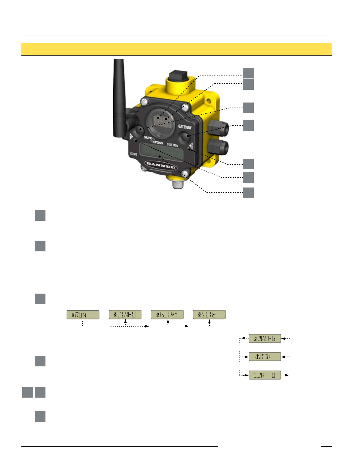
DX80 Gateway and Node Front Panel Interface
Rotary Switches: Used to set Network ID & Device Address
1
2
3
4
5
6
7
Rotary Switch 1 (left)
1
Sets the Network ID (NID) to a hexidecimal value from 0 to F, for a total of 16 Network IDs. A Gateway and its corresponding
Nodes must be assigned the same Network ID.
Rotary Switch 2 (right)
2
On Gateway: Sets the Gateway’s LCD viewing device address. The Gateway is predefined as Device Address 0.
On Node: Sets the Node’s Device Address (hexidecimal 1 to F). Each Node within a network must have a unique Node
Device Address.
Push Buttons: Used to navigate the Gateway and Node menus and program device configurations
Push Button 1
3
Single-click to advance across all top-level DX80 menus.
Single-click to move down interactive menus, once a top-level menu is chosen.
Push Button 2
4
Double-click to select a menu and to enter manual scrolling mode.
Double-click to move up one level at a time.
5 6
2 P/N 128185 Rev B
LED 1 and 2
Provide real-time feedback to the user regarding RF link status, serial communications activity, and the error state.
LCD Display
7
Six-character display provides run mode user information and shows enabled I/O point status. This display allows the user
to conduct a Site Survey (RSSI) and modify other DX80 configuration parameters without the use of a PC or other external
software interfaces. On the Node, after 15 minutes of inactivity, the LCD goes blank. Press any button to refresh the display.
Banner Engineering Corp. • Minneapolis, MN U.S.A.
www.bannerengineering.com • Tel: 763.544.3164
SureCross™ DX80 Quick Start Guide
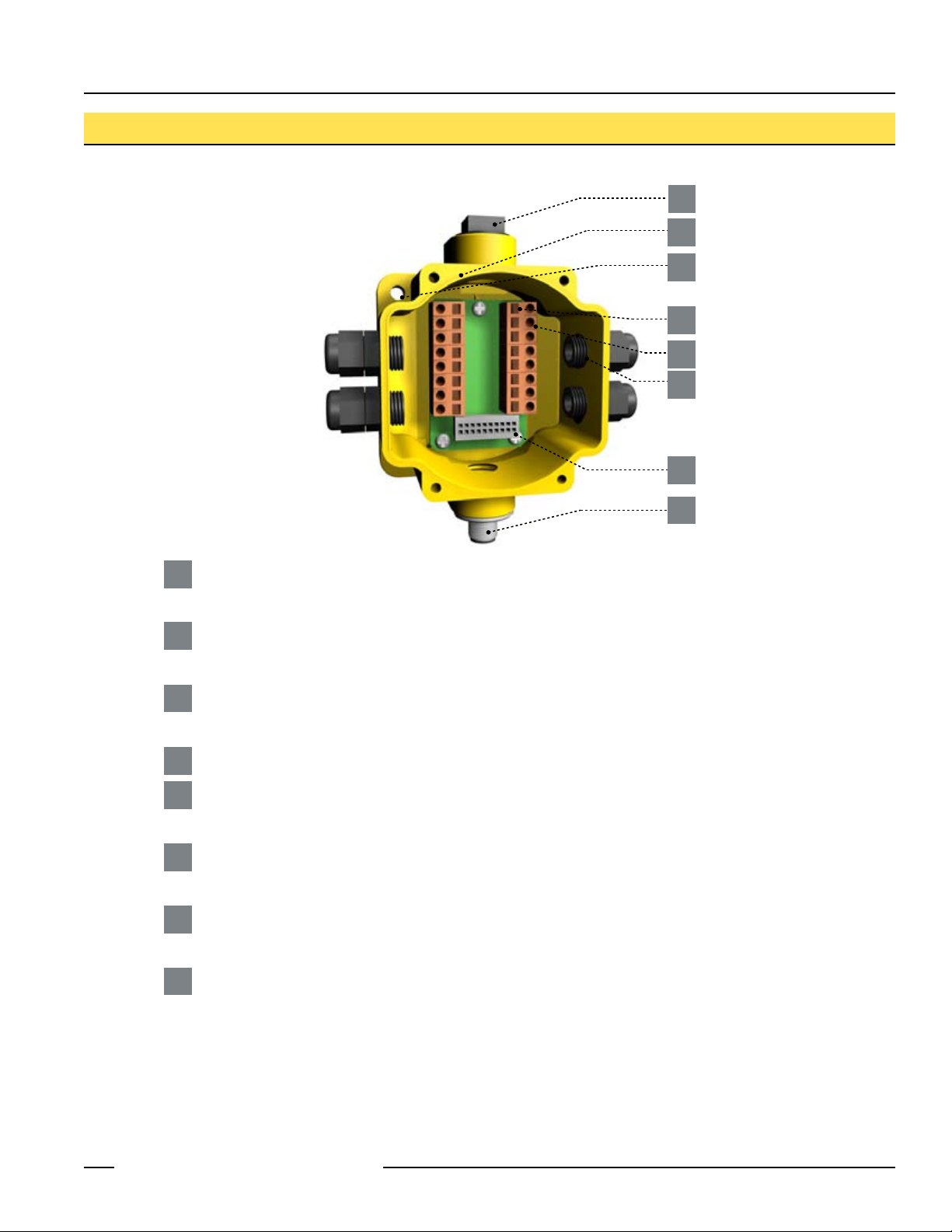
DX80 Gateway and Node Wiring Chamber
1
2
3
4
5
6
7
8
Port, NPT Gland, or Plug
1
If unused, install the provided plug into the 1/2 NPT threaded port. Use PTFE tape if an IP67 seal is required.
Housing
2
The rugged, industrial DX80 housing meets IEC IP67 standards.
Mounting Hole, #10/M5 Clearance
3
Mounting Holes accept metric M5 or UNC/UNF #10 hardware -- DIN rail mount adapter bracket available
Wiring Terminal Strip
4
Wiring Terminal
5
The 16 spring-clip type wiring terminals accept wire sizes: AWG 12-28 or 2.5 mm
Port, PG-7 Gland or Blank
6
The PG-7 threaded ports can accept provided cable glands or blanks.
Ribbon Connector
7
Ribbon cable connects wiring base to LCD/radio.
5-Pin M12 Euro-style quick-disconnect fitting
8
2
Banner Engineering Corp. • Minneapolis, MN U.S.A.
www.bannerengineering.com • Tel: 763.544.3164
P/N 128185 Rev B 3
SureCross™ DX80 Quick Start Guide
NOD XX
M XX
R XX
Y XX
G XX
*
DINFO
*
FCTRY
*
SITE
*
DVCFG
*
DERR
*
RUN
AUTO
DISPLAY
LOOP
AUTO
DISPLAY
LOOP
AUTO
DISPLAY
LOOP
(DE V)
GATE WY
(NI D)
XX
(SL ID)
XX
(BA UD)
XX
(PR TY)
XX
(DE V)
GATE WY
(RA DIO
MICRO)
V 00.0 A
(LC D
MICRO)
V 00.0 A
(DX 80
S/N)
(0000)
(DX 80
MODEL)
(0000-00)
(PR OD
DATE)
(00-00)
Single-click
Button 2
Single-click
Button 2
Single-click
Button 2
Double-click
Button 2
ADJUST RIGHT
ROTARY SWITCH
TO SURVEY
RESPECTIVE NODE
Single-click
Button 2
Double-click
Button 2
Double-click Button 2
NOD XX
EC XX CLE AR
ERR
ERA SED
ERR
DIS ABL
*
ERR OR
DIS ABL IGN ORE
Nex t
Dev ice
Single-click Button 1 to advance through menu
AUTO
DISPLAY
LOOP
Single-click
Button 2
Single-click
Button 2
Single-click
Button 2
Single-click
Button 2
Single-click
Button 2
Single-click
Button 2
New Error
Detected
ADJUST RIGHT
ROTARY SWITCH
TO SURVEY
RESPECTIVE NODE
(DE V)
I/O XX
GATE WY
NID XX
ON/OFF
(DE V)
I/O XX
GATE WY
NID XX
ON/OFF
Eve n
Non e
Odd
Single-click
Button 2
Single-click
Button 2
SAVES
DISPLAYED
VALUE
Single-click B1
192 00
960 0
384 00
Single-click
Button 2
Single-click
Button 2
SAVES
DISPLAYED
VALUE
NEW XX
Single-click
Button 2
Single-click
Button 2
ADJUST LEFT
ROTARY SWITCH
TO SET
NETWORK ID
SAVES NEW
VALUES
CUR XX
Single-click
Button 2
Single-click
Button 2
ADJUST ROTARY
SWITCHES
TO SET
SLAVE ID
SAVES NEW
VALUES
(NID) (SLID) (BAUD) (PRTY)
Network ID Slave ID Baud Rate Parity
Single-click B1
NEW XX
Single-click
Button 1
Single-click
Button 1
Single-click
Button 1
Single-click
Button 1
Single-click Button 1 to advance through menu
(NA ME)
GATEWY
KIT
XX
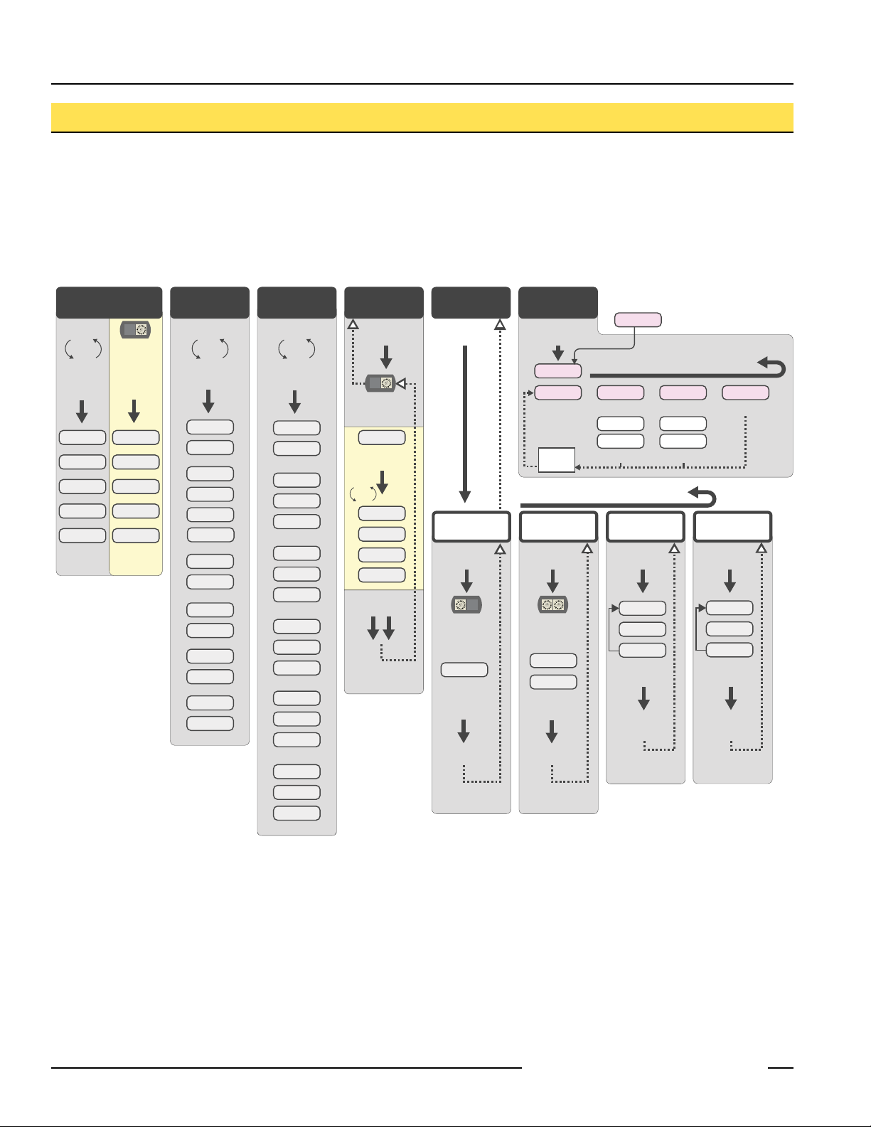
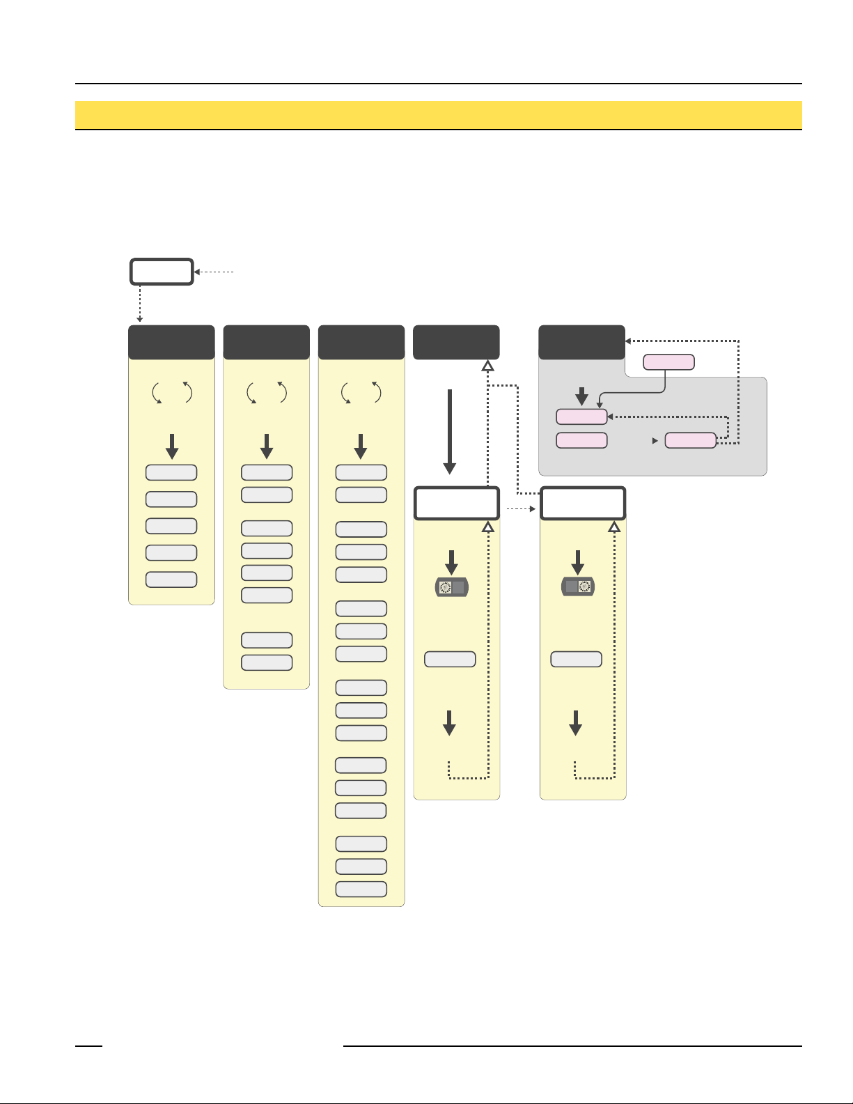
SureCross™ DX80 Gateway Setup Menu
When power is applied, the DX80 immediately begins running. The display screen autoscrolls through the *RUN menu and
communication begins between the Gateway and Node(s). Autoscrolling through the *RUN menu is the normal operating mode for all
devices on the wireless network.
From the *RUN Menu (or any menu), single-click button 1 to advance through the top-level menus.
To return to the top level menus and autoscrolling mode, double-click button 2 twice.*** To enter manual scrolling mode, double-click
button 2 at the top level menu. The device autoscrolls through the *RUN, *DINFO, and *FCTRY menus if paused on those menu
headings. If the device is paused on the *SITE, *DVCFG, or *DERR menu options, the display does not autoscroll.
**
** The Network ID (NID) can be set at any time from the left rotary switches. Once changed, allow five seconds for the devices to
update to the new NID.
*** At any point in the menu system, double-clicking Button 2 twice returns to the top level menu.
Navigating the menu:
* indicates a top level menu option
( ) indicates a sub-menu item
No characters indicate the value of the previous item
4 P/N 128185 Rev B
Banner Engineering Corp. • Minneapolis, MN U.S.A.
www.bannerengineering.com • Tel: 763.544.3164
SureCross™ DX80 Quick Start Guide
*
DINFO
*
RUN
*
FCTRY
*
DVCFG
*
DERR
AUTO
DISPLAY
LOOP
AUTO
DISPLAY
LOOP
AUTO
DISPLAY
LOOP
(DEV)
NOD XX
(NAME)
NODE XX
KIT
XXXXX
(NID)
XX
(DEV)
NOD XX
(RADIO
MICRO)
V 00.0 A
(DX80
S/N)
0x0000(2)
(LCD
MICRO)
0x0000(2)
(PROD
DATE)
(00-00)
Single-click
Button 2
NEW XX
Single-click
Button 2
Single-click
Button 2
SAVES NEW
VALUES
(NID)
Network ID
Single-click
Button 2
Double-click Btn 2
Double-click Btn 2
NEW XX
Single-click
Button 2
Single-click
Button 2
SAVES NEW
VALUES
(NADR)
Node Address
NOD XX
**
EC XX IGNORE
*
ERROR
Single-click Button 1
** LCD will display ‘NO ERR’ if no error is detected.
Single-click
Button 2
Single-click
Button 2
New Error
Detected
Single-click Button 2
OFF
Press and hold Button 1 from any top level menu to power down the Node.
Press and hold Button 1 from power down mode to enter RUN mode.
ADJUST LEFT
ROTARY SWITCH
TO SET
NETWORK ID
ADJUST RIGHT
ROTARY SWITCH
TO SET
NODE ADDRESS
Single-click
Button 1
(DEV)
I/O XX
NOD XX
NID XX
ON/OFF
Single-click
Button 1
Single-click
Button 1
Single-click
Button 1
(DX80
MODEL)
0x0000(2)
SureCross™ DX80 Node Setup Menu
When power is applied, the DX80 immediately enters *RUN mode. *RUN mode is the normal operating mode for all devices on the
wireless network.
From the *RUN Menu (or any menu), single-click button 1 to advance through the top-level menus.
To return to the top level menus and autoscrolling mode, double-click button 2 twice.*** To enter manual scrolling mode, double-click
button 2 at the top level menu. The device autoscrolls through the *RUN, *DINFO, and *FCTRY menus if paused on those menu
headings. If the device is paused on the *DVCFG or *DERR menu options, the display does not autoscroll.
** The Network ID (NID) and Node Address
(NADR) can be set at any time from the
rotary switches. The left rotary switch sets
the Network ID and the right rotary switch
sets the Node Address.
*** At any point in the menu system,
double-clicking Button 2 twice returns to
the top level menu.
** **
Navigating the menu:
* indicates a top level menu option
( ) indicates a sub-menu item
No characters indicate the value of the previous item
Node LCD Timeout: After 15 minutes of inactivity, the LCD screen stops displaying information. Press any button to refresh the display if
the Node has entered this energy-saving mode.
Banner Engineering Corp. • Minneapolis, MN U.S.A.
www.bannerengineering.com • Tel: 763.544.3164
P/N 128185 Rev B 5
SureCross™ DX80 Quick Start Guide
NODE
GATEWAY
GATEWAY
GATEWAY
NODE
NODE
NODE
NODE
NODE
7
NID
8
NID
9
NID
NID: 9
Device: 1
NID: 7
Device: 2
NID: 8
Device: 2
NID: 8
Device: 1
NID: 7
Device: 1
NID: 9
Device: 2
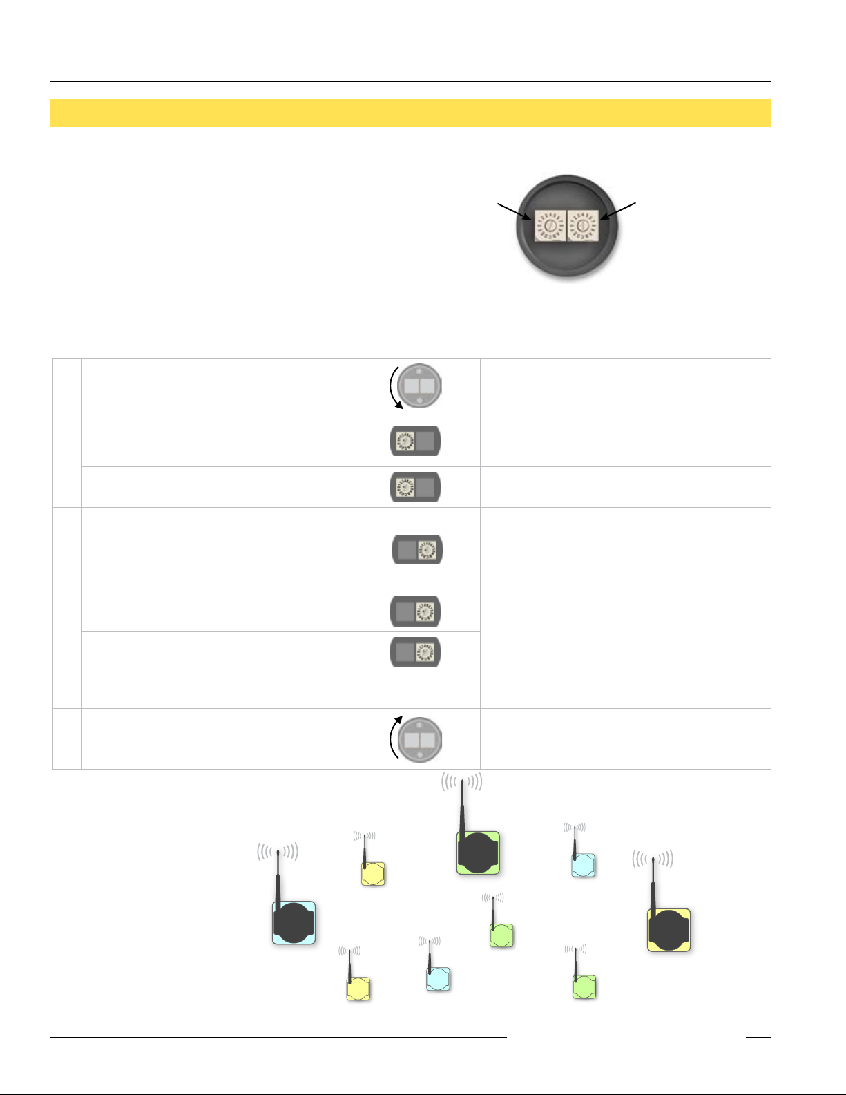
Quick Start: STEP 1
The wireless RF network is defined by the Network ID (NID)
assigned to the Gateway and its Nodes. Each device within
this common network must have a unique Device Address
assigned.
For factory configured kits, the Network ID and Device
Addresses have been assigned. Otherwise, use the Rotary
Switches (shown right) to define both the NID and Device
Address for each device. Follow the steps below to set up
your DX80 network.
User Action
Remove rotary switch access covers.
On the Gateway, set the Left Rotary Switch to 1.
SET NETWORK ID
On all Nodes (within the same network), set the Left
Rotary Switch to 1.
On the Gateway, set the Right Rotary Switch to 0.
On the first Node (Device Address = 1), set the Right
Rotary Switch to 1.
On the second Node (Device Address = 2), set the Right
Rotary Switch to 2.
SET DEVICE ADDRESS
Continue setting the Device Address for each additional
Node using a unique number (..3,4,5).
> Set Network ID & Device/Node Address
Network ID (NID) Device Address
Rotary Switches on
Gateway and Node
Display/Status
Turn counterclockwise to remove and clockwise to
tighten
The factory default NID setting on all devices is 1. Set
to another Network ID when operating more than one
network in the same area.
Assign the same NID to all devices within a single
network (hexidecimal 0-F).
A Device Address of 0 on the Gateway will display
settings for the Gateway itself. To view settings for
another device on the network, adjust the Right Rotary
Switch on the Gateway to the respective Device
Address.
Do not change the Device ID for preconfigured kits as
this would affect the factory mapping of the I/O.
Notes
Install rotary switch access covers. Please refer to the
installation section for IP67 instructions.
Multiple Networks
When more than one network is
operating in the same space, assign
a unique Network ID (NID) to each
network (shown right).
6 P/N 128185 Rev B
A successful RF link is identified by a blinking green LED
1 on each node.
Banner Engineering Corp. • Minneapolis, MN U.S.A.
www.bannerengineering.com • Tel: 763.544.3164
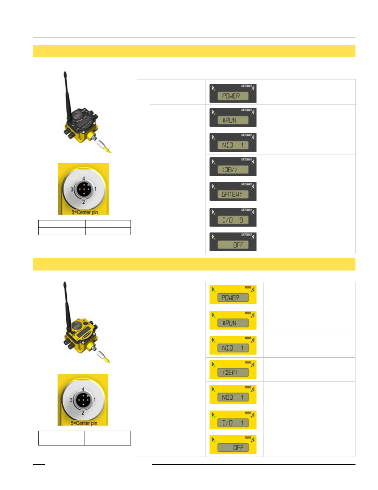
SureCross™ DX80 Quick Start Guide
Quick Start: STEP 2
To apply power to the Gateway, connect the 10-30V dc cable as shown.
User Action
Apply power...
The LCD display
shows the current I/O
status of the Gateway.
> Apply Power, Gateway
Gateway Pinout Diagram
Brown 1 10-30V dc Input
Blue 3 dc common
On the Gateway, the other pins are used for
RS485 communications
Display/Status
Notes
This reading occurs only when power is
applied to the Gateway.
The Gateway starts in *RUN mode.
Displays current Network ID (NID)
Device is ...
... Gateway (Device Address = 0)
Indicates the current status of the I/O.
The display cycles through each I/O
point of the device, then returns to
*RUN.
Quick Start: STEP 3
To apply power to the Node, connect the 10-30V dc cable or DX81 Battery Module as shown.
Apply power...
The LCD display
shows the current I/O
status of the Node.
Line Powered Node Pinout Diagram
Brown 1 10-30V dc Input
Blue 3 dc common
Note: Terminal block GND = dc common
Banner Engineering Corp. • Minneapolis, MN U.S.A.
www.bannerengineering.com • Tel: 763.544.3164
P/N 128185 Rev B 7
> Apply Power, Node
This reading occurs only when power
is applied to the Node.
The Node starts in *RUN mode.
Displays current Network ID (NID)
Device is ...
... Node 1 (Node Address = 1)
Indicates the current status of the I/O.
The display cycles through each I/O
point of the device, then returns to
*RUN.
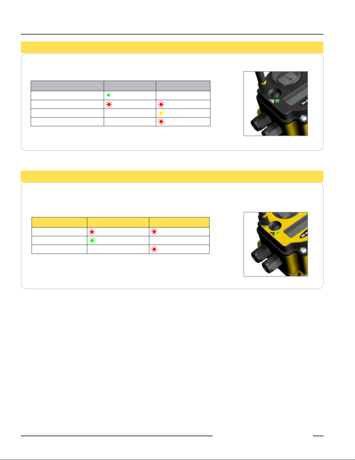
SureCross™ DX80 Quick Start Guide
Quick Start: STEP 4
Verify LED 1 is on and green.
Status LED 1 LED 2
Power ON Green ON —
System Error Red Flash Red Flash
Modbus Communication Active — Yellow Flash
Modbus Communication Error — Red Flash
Verify LED 1 is flashing Green and LED 2 is off. Until communication is established with
the Gateway, the Node’s LED 2 flashes Red. When communication is established, the
Node’s LED 1 flashes Green.
> Verify Communications, Gateway
> Verify Communications, Node
Status LED 1 LED 2
System Error Red Flash Red Flash (1 per sec)
RF Link Ok Green Flash (1 per sec) —
RF Link Error — Red Flash (1 per 3 sec)
If testing the Gateway and Node before installation, verify the Gateway and Node are at
least two meters apart or the communications may fail.
8 P/N 128185 Rev B
Banner Engineering Corp. • Minneapolis, MN U.S.A.
www.bannerengineering.com • Tel: 763.544.3164

SureCross™ DX80 Quick Start Guide
Quick Start: STEP 5
> Site Survey (optional)
A site survey analyzes the radio signal between a Gateway and a specified Node and reports the number of data packets missed or
received. Perform the Site Survey before permanently installing your network to ensure reliable communication. Use the Gateway to
perform a site survey analysis.
User Action
Remove Gateway rotary switch access cover.
To check the status of Node 1, change the
Gateway’s right rotary switch setting to 1
Single-click Gateway push button 1 Device Information menu
Single-click Gateway push button 1 Factory Settings menu
Display/Status
The Gateway is now enabled to read the status of
Node 1; the display scrolls through the Node’s I/O
status.
Notes
SITE SURVEY MENU
Single-click Gateway push button 1 Site Survey menu
Single-click Gateway push button 2 Site Survey will be conducted with Node 1
Single-click Gateway push button 2
Examine reception readings (M,R,Y,G) of the
Gateway at various locations. Note that the numbers
displayed are a percentage. M displays the percent
of missed packets while R, Y, and G display the
SURVEY READINGS
percent of received packets.
The Gateway analyzes the quality of the signal from
the selected Node by counting the number of data
packets it receives from the Node.
M = Percentage of missed packets
R = RED marginal signal
Y = YELLOW good signal
G = GREEN excellent signal
When possible, install all devices in positions that
optimize the percentage of YELLOW and GREEN data
packets received.
Double-click Gateway push button 2 End Site Survey
Change right rotary switch back to 0 (Gateway) Change the device readings back to the Gateway
Double-click Gateway push button 2 Move back to the top level menu
Single-click Gateway push button 1 Return to RUN mode
Single-click Gateway push button 1
Single-click Gateway push button 1
RETURN TO RUN MODE
Install Gateway rotary switch access cover.
Banner Engineering Corp. • Minneapolis, MN U.S.A.
www.bannerengineering.com • Tel: 763.544.3164
P/N 128185 Rev B 9
Refer to the installation instructions to create an IP67
seal.

SureCross™ DX80 Quick Start Guide
Quick Start: STEP 6
Avoid Direct Sunlight
To minimize the damaging effects of
ultra-violet radiation, avoid mounting the
Gateway or Node facing intense direct
sunlight.
Mount the DX80 within a protective
•
enclosure,
Mount the DX80 under an overhang or
•
other source of shade,
Install the DX80 indoors, or
•
Face the unit north when installing
•
outside.
Avoid Collecting Rain
When possible, mount the DX80 where
rain or snow will drain away from the unit.
Mount the units vertically so that
•
precipitation, dust, and dirt do not
accumulate on permeable surfaces.
Avoid mounting the units on flat or
•
concave surfaces, especially if the
display will be pointing up.
> Installation
Ideal Mounting Conditions
Reduce Chemical Exposure
Before installing the DX80 units in a
chemically harsh environment, contact
Banner for more information regarding the
life-expectancy. Solvents, oxidizing agents,
and other chemicals will damage the DX80.
Minimize Mechanical Stress
While the DX80 is very durable, it is a
sophisticated electronic device that is
sensitive to shock and excessive loading.
Avoid mounting the units to an object
•
that may be shifting or vibrating
excessively. High levels of static
force or acceleration may damage the
housing or electronic components.
Do not subject the DX80 to external
•
loads. Do not step on the DX80 or use
it as a handgrip.
Do not allow long lengths of cable to
•
hang from the DX80 glands. Cabling
heavier than 100 grams should be
supported instead of allowed to hang
from the DX80 housing.
10 P/N 128185 Rev B
Banner Engineering Corp. • Minneapolis, MN U.S.A.
www.bannerengineering.com • Tel: 763.544.3164

SureCross™ DX80 Quick Start Guide
Installation - Weather-Proofing Glands and Plugs
Watertight Glands and Plugs
Rotary Switch Access Cover
Check the rotary switch access cover
o-ring every time the access cover is
removed. Replace the o-ring when it is
damaged, discolored, or showing signs of
wear. The o-ring should be:
Seated firmly against the threads
•
without stretching to fit or without
bulging loosely, and
Pushed against the flanged cover.
•
When removing or closing the rotary switch
access cover, manually twist the cover
into position. Do not allow cross-threading
between the cover and the DX80 face.
Watertight 1/2” NPT Plug
Seal the 1/2” NPT port if it is not used. To
install a watertight NPT plug:
Wrap 12 to 16 passes of PTFE
1.
tape evenly across the length of the
threads.
Manually thread the plug into the
2.
housing port until reaching some
resistance.
Using a 9/16” crescent wrench, turn
3.
the plug until all the plug’s threads are
engaged by the housing port.
If the DX80 is mounted outdoors or will be
exposed to moisture, dirt, or dust, follow
these steps to weatherproof the units.
Watertight Glands
To make the glands watertight:
Wrap four to eight passes of
1.
polytetrafluoroethylene (PTFE) tape
around the threads as close as
possible to the hexagonal body of the
gland.
Manually thread the gland into the
2.
housing hole. Never apply more than
10 in-lbf of torque to the gland or its
cable clamp nut.
Note, these instructions apply both to the
PG-7 glands and the 1/2” NPT gland.
Watertight PG-7 Plug
Seal any unused PG-7 (small) access
holes with one of the supplied black plastic
plugs. To install a watertight PG7 plug:
Wrap four to eight passes of PTFE
1.
tape around the plug’s threads, as
close as possible to the flanged
surface.
Carefully thread the plastic plug
2.
into the vacant hole in the DX80
housing and tighten using a slotting
screwdriver. Never apply more than
10 in-lbf torque to the plastic plug.
Once the cover is in place and manually
tightened, use a small screwdriver (no
longer than five inches total length) as a
lever to apply enough torque to bring the
rotary switch access cover even with the
DX80 cover surface.
Banner Engineering Corp. • Minneapolis, MN U.S.A.
www.bannerengineering.com • Tel: 763.544.3164
P/N 128185 Rev B 11

SureCross™ DX80 Quick Start Guide
A wireless network can be hindered by
radio interference and obstructions in the
path between a receiver and transmitter.
To achieve the best radio performance,
carefully consider the installation locations
for the Gateways and Nodes.
Quick Tips
Clear Communication Paths
Orient the external antenna vertically for
optimal RF communication. If necessary,
consider changing the height of the DX80
position to improve reception levels.
Increase Height of DX80 Units
12 P/N 128185 Rev B
Banner Engineering Corp. • Minneapolis, MN U.S.A.
www.bannerengineering.com • Tel: 763.544.3164

SureCross™ DX80 Quick Start Guide
Maintenance and Parts Installation
Main Body Gasket
Check the main body gasket every time the
DX80 is opened. Replace the gasket when
it is damaged, discolored, or showing signs
of wear. The gasket must be:
Fully seated within its channel along
•
the full length of the perimeter, and
Positioned straight within the channel
•
with no twisting, stress, or stretching.
Rotary Switch Access Cover O-Ring
Check the rotary switch access cover
o-ring every time the access cover is
removed. Replace the o-ring when it is
damaged, discolored, or showing signs of
wear. The o-ring should be:
Seated firmly against the threads
•
without stretching to fit or without
bulging loosely, and
Pushed against the flanged cover.
•
When removing or closing the rotary switch
access cover, manually twist the cover
into position. Do not allow cross-threading
between the cover and the DX80 face.
Main Body Gasket
Rotary Access O-Ring
Once the cover is in place and manually
tightened, use a small screwdriver (no
longer than five inches total length) as a
lever to apply enough torque to bring the
rotary switch access cover even with the
DX80 cover surface.
Replacing O-Rings
Please refer to the list of replacement
parts on page 22 and contact Banner
Engineering with any questions.
Banner Engineering Corp. • Minneapolis, MN U.S.A.
www.bannerengineering.com • Tel: 763.544.3164
P/N 128185 Rev B 13

SureCross™ DX80 Quick Start Guide
DX80 Battery Replacement
Battery Replacement
To replace the lithum “D” cell battery in the
DX81 FlexPower battery kit,
Remove the four screws mounting the
1.
battery pack face plate to the body.
Remove the face plate.
2.
Remove the discharged battery and
3.
replace with a new battery. Verify
the battery’s positive and negative
terminals align to the positive and
negative terminals of the battery
holder mounted within the case.
After replacing the battery, allow up
4.
to 60 seconds for the device to power
up.
When removing the battery, press the
battery towards the negative terminal
to compress the spring. Pry up on the
battery’s positive end to remove from the
battery holder.
Properly dispose of your used battery by
taking it to a hazardous waste collection
site, an e-waste disposal center, or any
other facility qualified to accept lithium
batteries.
As with all batteries, these are a fire,
explosion, and severe burn hazard. Do not
burn or expose them to high temperatures.
Do not recharge, crush, disassemble, or
expose the contents to water.
14 P/N 128185 Rev B
Banner Engineering Corp. • Minneapolis, MN U.S.A.
www.bannerengineering.com • Tel: 763.544.3164

SureCross™ DX80 Quick Start Guide
Host Network - Gateway
Setting up the Network and Device IDs, powering up the devices, and conducting the Site Survey for a host-connected network is the
same as for the standard DX80 wireless system. All device I/O for the network is accessed using the host/master device.
To access the Modbus device, you may first need to configure system-level communication parameters on the DX80 Gateway, in
addition to the serial hookups shown below. The following procedure is necessary to change the Gateway Slave ID, Baud Rate, and
Parity.
Parameter Description
Slave ID (Default = 1)
Baud Rate (Default = 19200)
Parity (Default = None) Defines serial parity (none, even, or odd) between Gateway and Host.
Defines the slave number (01-99) for the serial Modbus RTU protocol. When operating more than one
network with a Modbus Master device, change the Slave IDs.
Defines communication data rate (19.2, 38.4 or 9.6 kbps) between the Gateway and the Host through the
serial interface.
Gateway (Host-Connected) Pinout Diagram
Brown 1 10-30V dc Input
White 2 RS485 / D1 / B /+
Blue 3 Ground Input
Black 4 RS485 / D0 / A / Gray 5 Comms Gnd
Wiring: 5-pin Euro pinouts for 485+, 485- and
Comms ground
Banner Engineering Corp. • Minneapolis, MN U.S.A.
www.bannerengineering.com • Tel: 763.544.3164
P/N 128185 Rev B 15

SureCross™ DX80 Quick Start Guide
Host Network - Gateway (con’t)
Setting the Slave ID, Baud Rate, and Parity
Similar to Network ID, the Slave ID, Baud Rate, and Parity parameters can be changed in the Device Configuration (*DVCFG) system
menu option.
Follow the top level system menu through *DVCFG to the Slave ID (SLID) parameter. The LCD displays an alternating current value and
new value for the parameter.
User Action Display/Status Notes
On the Gateway, single-click button one to move across the top level
menu options to the “Device Configuration” menu
Single-click Gateway push button 2
Single-click Gateway push button 1 to move to the Slave ID field. Default value is 1
Single-click Gateway push button 2
Using 0-9 on the left rotary switch and 1-9 on
SET SLAVE ID
the right switch, set the rotary switches to the
desired Slave ID
Single-click Gateway push button 2 to save the new Slave ID.
Single-click Gateway push button 1 to move to the next menu option,
the BAUD rate.
Single-click Gateway push button 2 to display the current setting.
Single-click Gateway push button 1 to cycle through the available
options. Stop on the desired setting.
SET BAUD RATE
Single-click Gateway push button 2 to save the new setting.
To navigate to the *DVCFG
(Device Configuration) menu,
see page 6.
The new Slave ID is defined
by the current position of the
rotary switches.
Select between 01 to 99.
The factory default is set
to 1. Change the Slave ID
when running more than one
network into the Modbus
Master device.
The options are 9600, 19200,
38400. The factory default is
19200.
Single-click Gateway push button 1 to move to the next field, the
PARITY field.
Single-click Gateway push button 2 to display the current setting.
Single-click Gateway push button 1 to cycle through the available
SET PARITY
options. Stop on the desired setting.
Single-click Gateway push button 2 to save the new setting.
Adjust the left rotary switch back to NID value.*
Adjust the right rotary switch back to zero.
Double-click Gateway push button 2 to return to the Device
Configuration (*DVCFG) menu.
Click Gateway push button 1 until reaching the *RUN menu option.
* To avoid losing the network connection between the Gateway and Nodes, reset the rotary switches back to their appropriate values before leaving the
*DVCFG sub-menus. If the Gateway and Nodes lose their connection, the network may take up to 20 seconds to re-synchronize.
Banner Engineering Corp. • Minneapolis, MN U.S.A.
16 P/N 128185 Rev B
www.bannerengineering.com • Tel: 763.544.3164
The options are NONE,
EVEN, ODD. The factory
default is NONE.

SureCross™ DX80 Quick Start Guide
65.0 mm
(2.56")
65.0 mm
(2.56")
80.3 mm
(3.16")
80.8 mm
(3.18")
60 mm
(2.36")
120 mm
(4.72")
127 mm
(5")
19 mm
(0.75")
30.65 mm
(1.21")
22.2 mm
(.875")
7.9 mm
(0.31")
7.65 mm
(0.30")
14.67 mm
(0.578")
DX80 Gateway and Node Dimensions
Banner Engineering Corp. • Minneapolis, MN U.S.A.
www.bannerengineering.com • Tel: 763.544.3164
P/N 128185 Rev B 17

SureCross™ DX80 Quick Start Guide
Troubleshooting
RF Link Time-Out and Recovery
The SureCross™ DX80 wireless devices employ a deterministic link time-out method to address RF link interruption or failure. As
soon as a specific Node/Gateway RF link fails, all pertinent wired outputs are de-energized until the link is recovered (see component
data sheet for more information.) Through this process, users of Banner wireless networks can be assured that disruptions in the
communications link will result in predictable system behavior.
The link time-out feature uses a fully-acknowledged polling method to determine the RF link status of each Node on the network. If after
a specified number of sequential polling cycles the Node does not acknowledge a message, the Gateway considers the link with the
Node timed out. LCD displays on both the Node and Gateway show *ERROR. Following a time-out, the Node de-energizes outputs and
the Gateway sets all outputs linked to the Node in question to a de-energized state. Inputs from the Nodes are mapped to outputs on
the Gateway and are suspended during a link timeout.
Once a link has failed, the Gateway must receive a specified number of good RF communications packets from the Node in question
before the link is reinstated. Outputs are restored to current values when the link is recovered.
For information regarding Host-connected systems and link time-out and recover, please refer to Banner’s DX80 and Modbus Guide.
Link between Gateway and Node 1 timed out.
Link between Gateway and Node 1 recovered.
18 P/N 128185 Rev B
Banner Engineering Corp. • Minneapolis, MN U.S.A.
www.bannerengineering.com • Tel: 763.544.3164

SureCross™ DX80 Quick Start Guide
Troubleshooting (con’t)
A wireless network can be hindered by radio interference and by obstructions in the path of the receiver and transmitter. To achieve the best radio
performance possible, carefully consider the installation locations for Gateways and Nodes. The need for a clear path increases as the transmission
distance increases. Use Site Survey (RSSI) to confirm signal quality before fixing devices for permanent installation.
Problem Description
No LEDs, No LCD
display
Node flashes the red
LED (no sync)
Marginal Site Survey
(RSSI) results
No communications
with the DX80 Gateway
using RS485
DX80 Display shows
*ERROR
Possible Solutions
Basic power–up issues
DX80 devices should immediately display ‘POWER’ on the LCD for the first 5-10 seconds after power is applied.
•
For the Gateway, LED 1 will always be green when power is connected. The Node devices will flash a red LED 2
every three seconds or a green LED 1 every second depending upon the RF Link status.
Battery powered devices can be put into a power-down mode using button 1 on the front panel. To put a battery
•
device into power-down mode, hold button 1 for three to five seconds. To make a battery device come out of
power-down mode, hold button 1 for three to five seconds.
Recheck the power connections and power requirements. Line powered devices require 10 to 30V dc. The DX81
•
Battery Module provides 3.6V dc.
After replacing the battery, allow up to 60 seconds for the device to power up.
•
DX80 devices will not synchronize
There are two things that MUST be set on every Node device to make it synchronize with the Gateway device:
•
1) The Network ID on the Node must match the Gateway Network ID. (0-15)
2) Each node within that network must have the Device ID rotary switch set to a unique number (1-15). Refer to
“Getting Started – Multiple Networks, Setting Network ID”
If the Gateway and Node are less than two meters apart, the devices may not communicate properly (radios may
•
saturate).
The Gateway and Node may be too far apart to achieve sync – consult factory for options.
•
A qualified antenna should be mounted on both the Gateway and Node devices.
•
After any system parameter changes, cycle power to cause the devices to resync with the network.
•
If a Node device loses synchronization with the network, it is programmed to try to acquire sync for five seconds,
•
then sleep for 15 seconds. Synchronizing may require up to 20 seconds.
Recycle power on the Gateway and Node devices.
•
Site survey (RSSI) returns > 30 MISSED packets
If the distance between devices is greater than about 5,000 meters (3 miles) line-of-sight *OR* objects, such as
trees or man-made obstructions, interfere with the path, and the MISSED packet count exceeds 30 per 100 packets,
consider the following steps:
Raise the DX80 units to a higher elevation – either by physically moving the devices or installing the antenna(s)
•
remotely at a higher position.
Use high-gain antenna(s) such as Yagi and/or Omni (see Accessories).
•
Decrease the distance between devices.
•
DX80 Gateway will not talk with the host system
Default communications parameters for the RS485 are: 1 start bit, 8 data bits, no parity, 1 stop bit and 19.2k baud.
•
The DX80 Gateway uses Modbus RTU protocol for all communications. The supported Modbus function codes are
3, 6, and 16.
Make sure the DX80 model supports RS485 serial communications.
•
Make sure the Slave ID is set properly for the bus environment. Factory default Slave ID = 1.
•
Factory default for the Modbus timeout is set to four seconds.
•
RS485 termination or biasing is not supplied on the DX80 Gateway and should be provided externally to the DX80.
•
(Termination is not required by the DX80 Gateway, proper biasing of the serial lines is required.)
RF link time-out and recovery
The Gateway utilizes fully-acknowledged polling to ensure each Node RF link is robust. Consequently, if after
•
a prescribed number of sequential polling cycles are not acknowledged by a Node, the Gateway considers the
particular link with that Node to be timed out. All outputs on the Node in question will be set to “OFF” (discrete) or
“0” (analog, regardless of type).
If the Node’s RF link is recovered and the Gateway can determine that enough acknowledged polling messages
•
have been accumulated, then the link is reinstated and outputs are restored to the current values.
Banner Engineering Corp. • Minneapolis, MN U.S.A.
www.bannerengineering.com • Tel: 763.544.3164
P/N 128185 Rev B 19

SureCross™ DX80 Quick Start Guide
Troubleshooting (con’t)
Problem Description
Particular inputs and/or
outputs are not working
Possible Solutions
I/O functionality
Use manual scrolling mode within *RUN to freeze the I/O status on the LCD display for the device in question.
•
Verify that when the input device changes state or changes value, the LCD mirrors the behavior.
Also verify that the LCD on the output side mirrors the linked input’s behavior. If the input device state, LCD
•
on origination DX80, and LCD on destination DX80 all behave exactly the same, there may be a wiring issue
or an interfacing problem. Consult factory.
Accessories and Replacement Parts - 900 MHz and 2.4 GHz
Model Number Description
Antennas Banner offers a range of omni-directional and directional (Yagi) antennas for use with the SureCross™ DX80
wireless network. For more information on antenna specifications and the options available for your system, please
contact the applications engineers at Banner Engineering Corp.
O-Rings BWA-ORING-001 O-Ring, Rotary Access Cover, PG21
BWA-GASKET-001 O-Ring, Body Gasket
BWA-CLRCOVER-001 Rotary Access Cover, Clear Plastic
Hardware BWA-HW-001 Mounting Hardware, DX80
BWA-HW-002 Access Hardware (Plugs, Glands), DX80
SMBDX80DIN Bracket Assembly, DIN Rail, for DX80
BWA-HW-003 Tape, PFTE Sealant
BWA-HW-004 Screws, Cover Mount, #8-32 x 3/4, 18-8 SS
Power DX81 Battery Pack Kit, DX81, with mounting hardware
DX121 Battery Pack Kit, DX121, 6 cells
BWA-BATT-001 Replacement Battery, 3.6V, “D” Lithium Cell
SPS101Q DC Power Supply, 120mA, 12-30V dc, 5-pin Euro
SPS101QP DC Power Supply, 120mA, 12-30V dc, 5-pin Euro, pigtail
PS24W DC Power Supply, 500mA, 24V dc
EZAC-E-QE5 DC Power Supply, 700mA, 24V dc, 5-pin Euro QD
EZAC-E-QE5-QS5 DC Power Supply, 700mA, 24V dc, 5-pin M12 Euro QD
Cabling MQDC1-506 2M Cord Set, 2 Meter, 5-pin, 5-conductor, MQDC1-506 2M
MQDC1-506.5 Cord Set, 0.5 Meter, 5-pin, 5-conductor, MQDC1-506.5
BWA-RIBBON-001 Ribbon Cable, 20 pin DBL socket
BWC-LFNMN Lightning Suppressor, 900 MHz, 2.4 GHz
There is a wide range of antenna cabling available. Please contact Banner Engineering Corp for more information
or for specific cable lengths and connectors.
20 P/N 128185 Rev B
Banner Engineering Corp. • Minneapolis, MN U.S.A.
www.bannerengineering.com • Tel: 763.544.3164

SureCross™ DX80 Quick Start Guide
Agency Certifications
Industry Canada
This Class A digital apparatus meets all requirements of the Canadian Interference Causing Equipment Regulations. Operation
is subject to the following two conditions: (1) this device may not cause harmful interference, and (2) this device must accept any
interference received, including interference that may cause undesired operation.
Cet appareil numérique de la classe A respecte toutes les exigences du Règlement sur le matériel brouiller du Canada. Le present
appareil numérique n’emet pas de bruits radioélectriques dépassant les limites applicables aux appareils numeriques de le Classe A
préscrites dans le Reglement sur le brouillage radioélectrique édits par le ministere des Communications du Canada.
Banner Engineering Corp. • Minneapolis, MN U.S.A.
www.bannerengineering.com • Tel: 763.544.3164
P/N 128185 Rev B 21

SureCross™ DX80 Quick Start Guide
FCC Certification - 900 MHz
FCC Certification
The DX80 Module complies with Part 15 of the FCC rules and regulations.
FCC ID: TGUDX80 This device complies with Part 15 of the FCC Rules. Operation is subject to the following two conditions: (1) this
device may not cause harmful interference, and (2) this device must accept any interference received, including interference that may
cause undesired operation.
FCC Notices
IMPORTANT: The DX80 Modules have been certified by the FCC for use with other products without any further certification (as per
FCC section 2.1091). Changes or modifications not expressly approved by the manufacturer could void the user’s authority to operate
the equipment.
IMPORTANT: The DX80 Modules have been certified for fixed base station and mobile applications. If modules will be used for portable
applications, the device must undergo SAR testing.
IMPORTANT: If integrated into another product, the FCC ID label must be visible through a window on the final device or it must be
visible when an access panel, door, or cover is easily removed. If not, a second label must be placed on the outside of the final device
that contains the following text: Contains FCC ID: TGUDX80.
Note
This equipment has been tested and found to comply with the limits for a Class B digital device, pursuant to Part 15 of the FCC Rules.
These limits are designed to provide reasonable protection against harmful interference in a residential installation. This equipment
generates, uses, and can radiate radio frequency energy and, if not installed and used in accordance with the instructions, may cause
harmful interference to radio communications. However, there is no guarantee that interference will not occur in a particular installation.
If this equipment does cause harmful interference to radio or television reception, which can be determined by turning the equipment off
and on, the user is encouraged to try to correct the interference by one or more of the following measures:
Reorient or relocate the receiving antenna,
•
Increase the separation between the equipment and receiving module,
•
Connect the equipment into an outlet on a circuit different from that to which the receiving module is connected, and/or
•
Consult the dealer or an experienced radio/TV technician for help.
•
Antenna Warning WARNING: This device has been tested with Reverse Polarity SMA connectors with the antennas listed in Table 1
Appendix A. When integrated into OEM products, fixed antennas require installation preventing end-users from replacing them with nonapproved antennas. Antennas not listed in the tables must be tested to comply with FCC Section 15.203 (unique antenna connectors)
and Section 15.247 (emissions).
FCC-Approved Antennas
WARNING: This equipment is approved only for mobile and base station transmitting devices. Antenna(s) used for this transmitter must
be installed to provide a separation distance of at least 20 cm from all persons and must not be co-located or operating in conjunction
with any other antenna or transmitter.
DX80 Module may be used only with Approved Antennas that have been tested with this module.
Part Number Antenna Type Maximum Gain
— Integral antenna Unity gain
BWA-9O1-x Omni, 1/4 wave dipole ≤2 dBi
BWA-9O2-C Omni, 1/2 wave dipole, Swivel ≤2 dBi
BWA-9O6-A Omni Wideband, Fiberglass
Radome
BWA-9O5-B Omni Base Whip ≤7.2 dBi
BWA-9Y10-A Yagi ≤10 dBi
≤8.2 dBi
22 P/N 128185 Rev B
Table 1. Type certified Antenna
Banner Engineering Corp. • Minneapolis, MN U.S.A.
www.bannerengineering.com • Tel: 763.544.3164

FCC Certification - 2.4 GHz
FCC Certification
The DX80 Module complies with Part 15 of the FCC rules and regulations.
SureCross™ DX80 Quick Start Guide
FCC ID: UE300DX80-2400
this device may not cause harmful interference, and (2) this device must accept any interference received, including interference that
may cause undesired operation.
This device complies with Part 15 of the FCC Rules. Operation is subject to the following two conditions: (1)
FCC Notices
IMPORTANT: The DX80 Modules have been certified by the FCC for use with other products without any further certification (as per
FCC section 2.1091). Changes or modifications not expressly approved by the manufacturer could void the user’s authority to operate
the equipment.
IMPORTANT: The DX80 Modules have been certified for fixed base station and mobile applications. If modules will be used for portable
applications, the device must undergo SAR testing.
IMPORTANT: If integrated into another product, the FCC ID label must be visible through a window on the final device or it must be
visible when an access panel, door, or cover is easily removed. If not, a second label must be placed on the outside of the final device
that contains the following text: Contains FCC ID: UE300DX80-2400.
Note
This equipment has been tested and found to comply with the limits for a Class B digital device, pursuant to Part 15 of the FCC Rules.
These limits are designed to provide reasonable protection against harmful interference in a residential installation. This equipment
generates, uses, and can radiate radio frequency energy and, if not installed and used in accordance with the instructions, may cause
harmful interference to radio communications. However, there is no guarantee that interference will not occur in a particular installation.
If this equipment does cause harmful interference to radio or television reception, which can be determined by turning the equipment off
and on, the user is encouraged to try to correct the interference by one or more of the following measures:
Reorient or relocate the receiving antenna,
•
Increase the separation between the equipment and receiving module,
•
Connect the equipment into an outlet on a circuit different from that to which the receiving module is connected, and/or
•
Consult the dealer or an experienced radio/TV technician for help.
•
Antenna Warning WARNING: This device has been tested with Reverse Polarity SMA connectors with the antennas listed in Table 1
Appendix A. When integrated into OEM products, fixed antennas require installation preventing end-users from replacing them with nonapproved antennas. Antennas not listed in the tables must be tested to comply with FCC Section 15.203 (unique antenna connectors)
and Section 15.247 (emissions).
FCC-Approved Antennas
WARNING: This equipment is approved only for mobile and base station transmitting devices. Antenna(s) used for this transmitter must
be installed to provide a separation distance of at least 20 cm from all persons and must not be co-located or operating in conjunction
with any other antenna or transmitter.
DX80 Module may be used only with Approved Antennas that have been tested with this module.
Part Number Antenna Type Maximum Gain
— Integral antenna Unity gain
BWA-2O2-C Omni, 1/2 wave dipole, Swivel ≤2 dBi
BWA-2O5-C Omni, Collinear, Swivel ≤5 dBi
BWA-2O7-C Omni, Coaxial Sleeve, Swivel ≤7 dBi
Table 1. Type certified Antenna
Banner Engineering Corp. • Minneapolis, MN U.S.A.
www.bannerengineering.com • Tel: 763.544.3164
P/N 128185 Rev B 23

CAUTION . . .
Make no modifications
All specifications published in this document are subject to change. Banner reserves the right
to modify the specifications of products, prior to their order, without notice.
to this product.
Any modifications to this product not
expressly approved by Banner Engineering
could void the user’s authority to operate
the product. Contact the Factory for more
information.
P/N 128185 Rev B
Banner Engineering Corp., 9714 Tenth Ave. No., Minneapolis, MN USA 55441 • Phone: 763.544.3164 • www.bannerengineering.com • Email: sensors@bannerengineering.com
WARRANTY: Banner Engineering Corp. warrants its products to be free from defects for
one year. Banner Engineering Corp. will repair or replace, free of charge, any product of its
manufacture found to be defective at the time it is returned to the factory during the warranty
period. This warranty does not cover damage or liability for the improper application of
Banner products. This warranty is in lieu of any other warranty either expressed or implied.
 Loading...