

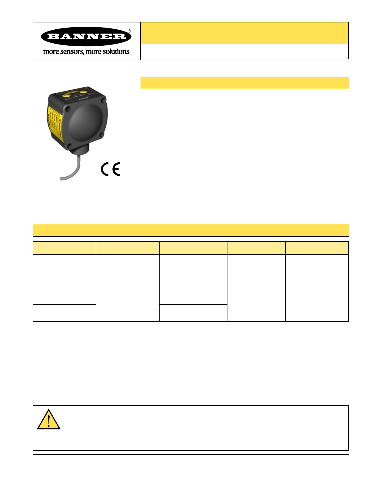
R-GAGE™ QT50R Series Sensor
Radar-Based Vehicle Detection Sensor
Features
• Reliably detects vehicles and trains based on frequency-modulated continuous-wave
(FMCW) radar technology
• Detects objects up to 7.2 m (24') away using a fixed background reference target up
to 8 m (26') away
• Detection is unaffected by wind or changing air temperatures
• Easy to set up using sealed push button or remote wire
• Operates in Industrial, Scientific, and Medical (ISM) telecommunication band; no
special license required
• 15 to 30V dc operation
• Rugged IP67 housing for harsh environments
Models
Models* Sensing Range Cable Telecom Approval Output
QT50R
QT50RQ 5-pin Euro-style integral QD
QT50RUS 5-wire, 2 m (6.5') cable
QT50RUSQ 5-pin Euro-style integral QD
* For 9 m cable, add suffix “W/30” to the model number of the cabled sensor (e.g., QT50R W/30). A QD model requires a mating cable. See page 7.
Objects:
0.5 to 7.2 m (1.6' to 24')
Background:
4 to 8 m (13' to 26')
5-wire, 2 m (6.5') cable
ETSI/EN 300 440
(EU except
UK and France)
Bipolar NPN and PNP
FCC Part 15
(USA)
WARNING . . . Not To Be Used for Personnel Protection
Never use these products as sensing devices for personnel protection. Doing so could lead to serious injury or death.
These sensors do NOT include the self-checking redundant circuitry necessary to allow their use in personnel safety applications. A
sensor failure or malfunction can cause either an energized or de-energized sensor output condition. Consult your current Banner
Safety Products catalog for safety products which meet OSHA, ANSI and IEC standards for personnel protection.
Printed in USA 08/06 P/N 124617 rev. C
R-GAGE™ QT50R Series Sensors
45° 45°
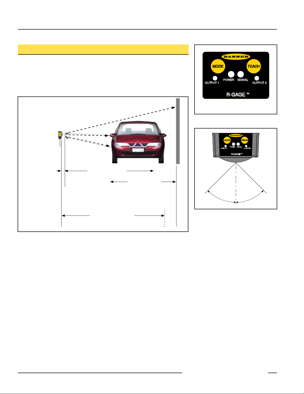
Overview
The R-GAGE sensor emits high-frequency radio waves from an internal antenna, which
forms a well-defined beam. Some of this emitted energy is reflected back to the receiving
antenna. Signal processing electronics determine the distance from the sensor to the
vehicle based on the time delay of the return signal. The sensor is configured to operate
like a retroreflective photoelectric sensor. See Figure 3.
R-GAGE Sensor
(not shown to scale)
Background Target
NOTE: The MODE button on this model is not
functional.
Figure 1. R-GAGE features
Dead Zone
0.5 m (1.6')
Detection Range
0.5 to 7.2 m (1.6' to 24')
Threshold Range
(90% of Taught Background Range)
Background Range
4 to 8 m (13' to 26')
Threshold
Figure 3. Threshold automatically placed at 90% of distance to background target that is
taught
Figure 2. R-GAGE field of view
2 P/N 124617 rev. C
Banner Engineering Corp. • Minneapolis, MN U.S.A.
www.bannerengineering.com • Tel: 763.544.3164
4
Push Button
R-GAGE™ QT50R Series Sensors
Sensor Programming
1. Mount the sensor securely. Align the sensor with the background target, making the
face of the Sensor as parallel as possible to the background target.
In programming mode (only after the TEACH push button is pressed), the red Signal
LED will flash faster as the alignment improves; solid ON is best. If the red Signal LED
does not flash, then the background target is not sufficient and a different target must
be used, such as a metal plate or a corner cube reflector.
2. Verify that the area between the sensor and the background is clear, and follow the
programming procedure in the table below.
General Notes on Programming
• Once the sensor enters TEACH mode, it will default to the previous settings and exit
TEACH mode after one minute.
• To exit TEACH mode and return to the previous settings, push and hold the TEACH
push button (or pulse the remote line) for more than two seconds.
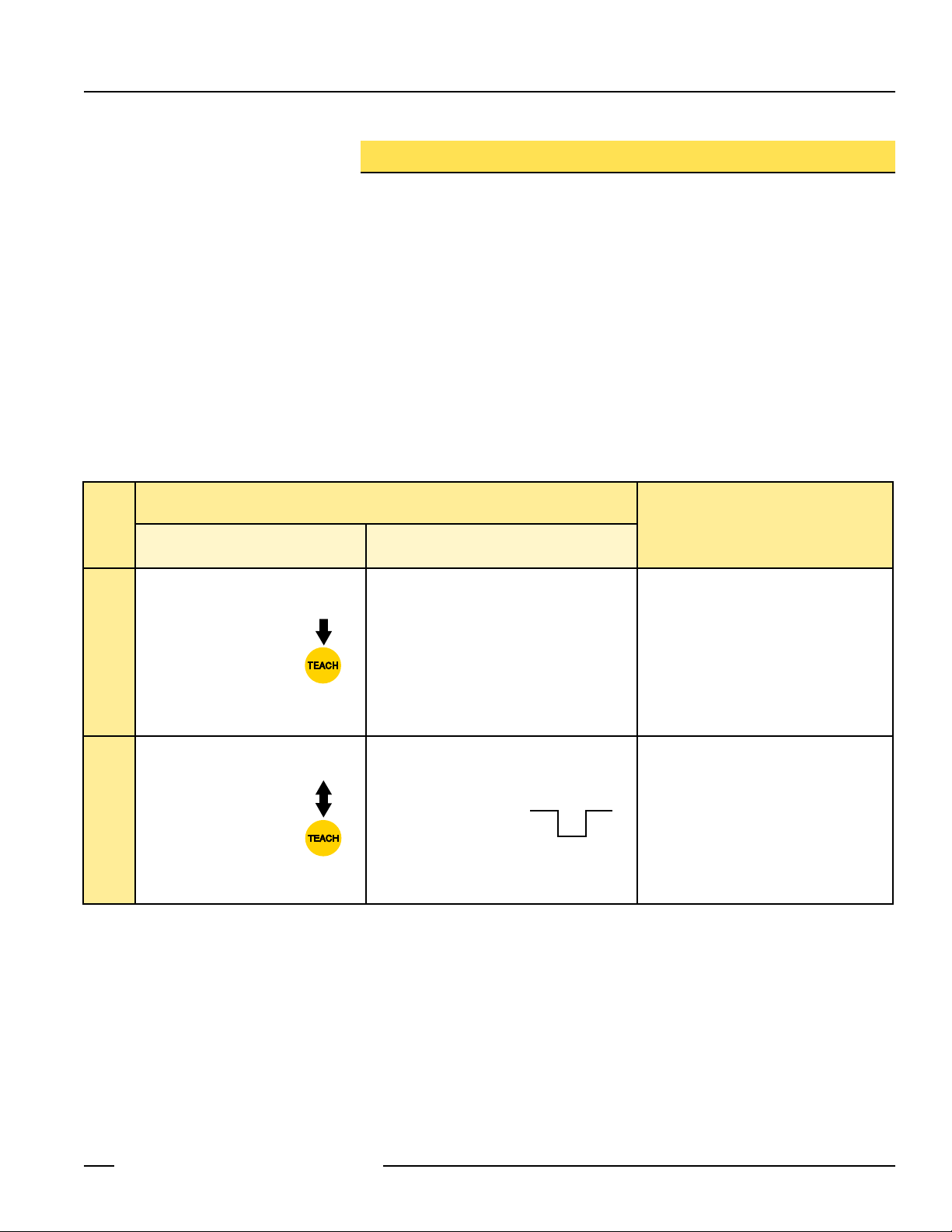
Procedure
Remote Line
0.02 sec. < T < 0.8 sec.
Result
• Push and hold TEACH
push button until
Output LEDs turn
ON Red
Programming Mode
• Press and release TEACH
push button
Reference Target
TEACH Background
• No action required; sensor is ready to be
aligned and programmed
• Pulse the remote line
Power LED: OFF
Output LEDs: ON Red
Signal LED: Flashes faster as background
signal strength increases (i.e.,
as alignment improves); solid
ON is best
Teach Accepted
Power LED: ON
Output LEDs: OFF
Signal LED: ON solid
Teach Unacceptable
Power LED: OFF
Output LEDs: ON
Sensor defaults to program mode.
Banner Engineering Corp. • Minneapolis, MN U.S.A.
P/N 124617 rev. C 3
www.bannerengineering.com • Tel: 763.544.3164

R-GAGE™ QT50R Series Sensors
Setup Procedure for Tunnel Train Detection
1. Mount the sensor such that Y is 1/3 of X, and align the sensor so the center of the
beam strikes the corner of the tunnel beyond the far rail, as shown in Figure 4.
2. Make sure the area between the sensor and the background is clear, and press the
TEACH button until the Output LEDs turn ON red.
3. Align the sensor. The red Signal LED will flash faster as alignment improves; solid ON
is best.
4. Press the TEACH button again. The Output LEDs turn OFF, and the red Signal LED
turns ON.
5. Verify proper setup by blocking the beam. The Output LEDs should turn ON yellow.
Figure 4. Setup for tunnel train detection
X
4 to 8 m
(13' to 26')
Y
4 P/N 124617 rev. C
Banner Engineering Corp. • Minneapolis, MN U.S.A.
www.bannerengineering.com • Tel: 763.544.3164

R-GAGE™ QT50R Series Sensors
CAUTION . . .
Make No Modifications
to this Sensor
Any modifications to this sensor not
expressly approved by Banner Engineering
could void the user’s authority to operate
the sensor. Contact the Factory for more
information.
Status Indicators
Power LED Indicates
OFF Power is OFF.
ON Green Power is ON.
Signal LED Indicates
TEACH Mode
(signal strength
indicator for
background)
RUN Mode
(alignment
indicator for
background
target taught)
Output LEDs Indicate
ON Red In TEACH mode.
ON Yellow In RUN mode; target is sensed and outputs are conducting.
OFF Background target is not sufficient; use a different
target.
ON Red (flashing) Frequency of flash indicates alignment. LED flashes
faster as alignment improves; solid ON indicates
best alignment.
OFF Background target is not being sensed.
ON Red (flashing) Frequency of flash is proportional to background
target taught; solid ON indicates best alignment.
Specifications
Specifications are subject to change without notice.
Range Sensor will detect a 1 m x 1 m metal plate at a distance of up to 7.2 m (24') when set up with a suitable
background target.
Detectable Objects Objects containing metal or other high-dielectric material
Operating Principle Frequency-modulated continuous-wave (FMCW) radar
Operating Frequency 24.05 to 24.25 GHz, ISM Band (varies slightly with national telecom regulations)
Supply Voltage 15 to 30V dc
Supply Protection Circuitry Protected against reverse polarity and transient overvoltages
Delay at Power-up Less than 1.5 seconds
Output Configuration Bipolar NPN and PNP outputs, 150 mA (derate 1 mA per °C above 25° C)
Output Protection Protected against short circuit conditions
Indicators Power LED: Green
Signal Strength LED: Red
Output LEDs: Yellow/Red
See “Status Indicators” above.
Adjustments TEACH programming button for setting background reference
Operating Temperature -20° to 55° C (-4° to 131° F)
Environmental Rating IEC IP67; NEMA 6
Connections 2 m (6.5') or 9 m (30') 5-conductor, shielded, PVC-jacketed attached cable or integral 5-pin Euro-style QD
Certifications
and ETSI/EN 300 440 or FCC Part 15, depending on model
Banner Engineering Corp. • Minneapolis, MN U.S.A.
P/N 124617 rev. C 5
www.bannerengineering.com • Tel: 763.544.3164

R-GAGE™ QT50R Series Sensors
bk
gy
bn
bu
wh
+15 - 30V dc
shield
0 - 2V dc
Load 1
Load 2
38.1 mm
(1.50")
46.1 mm
(1.82")
R45.0 mm
(R1.77")
66.0 mm
(2.60")
84.2 mm
(3.31")
33.0 mm
(1.30")
37.0 mm
(1.46")
74.1 mm
(2.92")
50.8 mm
(2.00")
50.8 mm
(2.00")
19.7 mm
(0.78")
37.0 mm
(1.46")
M30 X 1.5
ISO-6g
4X Ø4.4 mm
(Ø 0.17")
34.2 mm
(1.35")
Dimensions
Cabled Models QD Models
Hookup
NOTES:
• Cable and QD hookups are functionally identical.
• It is recommended that the shield wire be connected to earth ground or dc
common. Shielded cordsets are recommended for all QD models.
6 P/N 124617 rev. C
Banner Engineering Corp. • Minneapolis, MN U.S.A.
www.bannerengineering.com • Tel: 763.544.3164

R-GAGE™ QT50R Series Sensors
50.8 mm
(2.00")
58.7 mm
(2.31")
66.5 mm
(2.62")
30.0 mm
(1.18")
30 x 1.5 mm
internal thread
29.0 mm
(1.14")
12.7 mm
(0.50")
35.1 mm
(1.38")
35.1 mm
(1.38")
69.9 mm
(2.75")
7.1 mm
0.28 x 90 (2 Slots)
R 25.4 mm
(1.00")
ø30.1 mm
(1.19")
57.2 mm
(2.25")
25.4 mm
(1.00")
25.4 mm
(1.00")
ø 6.4 mm
(0.25" dia.)
57.2 mm
(2.25")
M12 x 1
ø 15 mm
(0.6")
44 mm max.
(1.7")
38 mm max.
(1.5")
M12 x 1
ø 15 mm
(0.6")
38 mm max.
(1.5")
White Wire
Blue Wire
Black Wire
Brown Wire
Gray Wire
Quick-Disconnect (QD) Cables
Style Model Length Dimensions Pinout
5-Pin
Euro-style
Straight
with shield
5-Pin
Euro-style
Right-angle
with shield
SMB30SC
MQDEC2-506
MQDEC2-515
MQDEC2-530
MQDEC2-506RA
MQDEC2-515RA
MQDEC2-530RA
2 m (6.5')
5 m (15')
9 m (30')
2 m (6.5')
5 m (15')
9 m (30')
• 30 mm split clamp with swivel, black
reinforced thermoplastic polyester
• Stainless steel hardware included
Mounting Brackets
SMB30MM
• 30 mm, 11-gauge, stainless steel bracket with
curved mounting slots for versatile orientation
• Clearance for M6 (1/4") hardware
Banner Engineering Corp. • Minneapolis, MN U.S.A.
P/N 124617 rev. C 7
www.bannerengineering.com • Tel: 763.544.3164

R-GAGE™ QT50R Series Sensors
WARRANTY:
one year. Banner Engineering Corp. will repair or replace, free of charge, any product of its
manufacture found to be defective at the time it is returned to the factory during the warranty
period. This warranty does not cover damage or liability for the improper application of Banner
products. This warranty is in lieu of any other warranty either expressed or implied.
P/N 124617 rev. C
Banner Engineering Corp., 9714 Tenth Ave. No., Minneapolis, MN USA 55441 • Phone: 763.544.3164 • www.bannerengineering.com • Email: sensors@bannerengineering.com
Banner Engineering Corp. warrants its products to be free from defects for
 Loading...