


Rhein Tech Laboratories, Inc. Client: Banner Engineering, Inc.
360 Herndon Parkway Model: Q120RA-US
Suite 1400 Standard: FCC 15.245
Herndon, VA 20170 FCC ID: UE3Q120RAUS
http://www.rheintech.com
Report #: 2012355
Appendix H: Manual
Please refer to the following pages.
Page 21 of 27
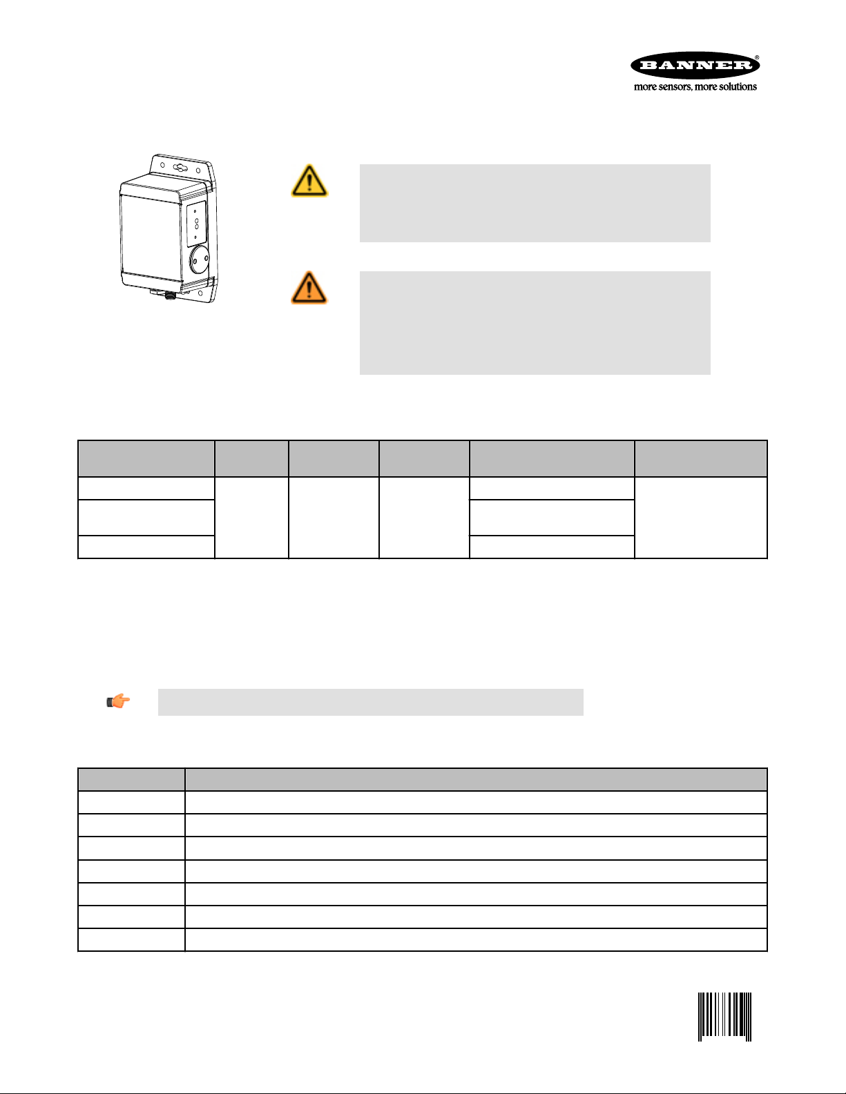
R-GAGE™ Q120RA-AF2 Sensor
0 157494 8
Radar-Based Dual-Zone Narrow-Beam Sensors for Detection of Moving and Stationary Targets
For complete technical information about this product, including dimensions, accessories, and specifications, see www.BannerEngineering.com and search 157494_web
CAUTION: Make No Modifications to this Product
Any modifications to this product not expressly approved by Banner Engineering
could void the user's authority to operate the product. Contact the Factory for
more information.
WARNING: Not To Be Used for Personnel Protection
Models
Never use this product as a sensing device for personnel protection. Doing
so could lead to serious injury or death. This product does NOT include the self-
checking redundant circuitry necessary to allow its use in personnel safety applications. A sensor failure or malfunction can cause either an energized or de-energized
sensor output condition.
Model Sensing
Q120RA-US-AF2
Q120RA-EU-AF2 Pending approval for Europe (except
Q120RA-UK-AF2 Pending approval for UK
Cabled models only are listed. For integral 5-pin Euro-style (M12) quick-disconnect fitting, add suffix "Q" to the model number (e.g., Q120RA-xx-AF2Q). *QD models
require a mating cordset.
Range
Two independ-
ent sensing
zones; 1 to 40+
meters (131 ft)
Connection Supply Voltage Telecom Approval Output
Pending approval for United States
5-wire 2 m (6.5 ft)
Integral cable
12 to 30V dc
UK) and China
DIP-switch-selectable NPN or
PNP; N.O. or N.C.
Sensor Configuration
The sensitivity, and output configuration can be selected via the DIP switches on the side of the sensor.
Use the included spanner to open the screw-off cover on the side of the sensor and access the DIP switches.
Important: Tighten the DIP switch cover a full quarter turn after contact to maintain the watertight seal.
DIP Switch Functions
Switches Function
A1, A2, A3, A4 Zone 1 Distance (detects objects from sensor face to this point)
A5, A6, A7 Zone 2 Distance, Offset from Zone 1
A8 Polarity
B1, B2, B3 Sensitivity (higher sensitivity sees weaker objects and has a larger beam pattern)
B4, B5, B6 Response Speed
B7 Normally Open/Normally Closed output functionality
B8 Not Used
DIP switch 1 is on the left and DIP switch 8 is on the right.
P/N 157494 Rev. C 8/21/2012

R-GAGE™ Q120RA-AF2 Sensor
Distance Settings
* Default settings
Zone 1 Distance
A1 A2 A3 A4
0 0 0 0 2 m (6.6 ft) 3.5 m (11.5 ft)
0 0 0 1 2.5 m (8.2 ft) 4 m (13.1 ft)
0 0 1 0 3 m (9.8 ft) 4.5 m (14.8 ft)
0 0 1 1 3.5 m (11.5 ft) 5 m (16.4 ft)
0 1 0 0 4 m (13.1 ft) 5.5 m (18.0 ft)
0 1 0 1 5 m (16.4 ft) 6 m (19.7 ft)
0 1 1 0 6 m (19.7 ft) 6.5 m (21.3 ft)
0 1 1 1 7 m (23.0 ft) 7 m (23.0 ft)
1* 0* 0* 0* 8 m (26.2 ft) 8 m (26.2 ft)
1 0 0 1 10 m (32.8 ft) 10 m (32.8 ft)
1 0 1 0 12 m (39.4 ft) 12 m (39.4 ft)
1 0 1 1 14 m (45.9 ft) 14 m (45.9 ft)
1 1 0 0 16 m (52.5 ft) 16 m (52.5 ft)
1 1 0 1 20 m (65.6 ft) 20 m (65.6 ft)
1 1 1 0 25 m (82.0 ft) 25 m (82.0 ft)
1 1 1 1 30 m (98.4 ft) 30 m (98.4 ft)
Distance
EU US, UK
Zone 2 Distance Offset from Zone 1
A5 A6 A7 Offset
0 0 0 2 m (6.6 ft)
0 0 1 4 m (13.1 ft)
0 1 0 6 m (19.7 ft)
0* 1* 1* 8 m (26.2 ft)
1 0 0 10 m (32.8 ft)
1 0 1 15 m (49.2 ft)
1 1 0 20 m (65.6 ft)
1 1 1 25 m (82.0 ft)
NOTE: Highest sensitivity is achieved only if the sensing distance is 36 m (118.1 ft) or less.
2 www.bannerengineering.com - tel: 763-544-3164 P/N 157494 Rev. C

R-GAGE™ Q120RA-AF2 Sensor
Sensitivity Selection
* Default settings
B1 B2 B3 Sensitivity
0* 0* 0* 8 (Highest)
0 0 1 7...
0 1 0 6 (High)
0 1 1 5...
1 0 0 4 (Medium)
1 0 1 3...
1 1 0 2 (Low)
1 1 1 1 (Lowest)
NOTE: Operation at a high sensitivity not guaranteed for a zone set beyond 45 m (147.6 ft)
Response Speed
* Default settings
B4 B5 B6 ON Total OFF Total Total
0 0 0 15 15 30
0 0 1 30 70 100
0 1 0 30 120 150
0* 1* 1* 50 300 350
1 0 0 50 600 650
1 0 1 30 1000 1030
1 1 0 120 600 720
1 1 1 120 6000 6120
Output Configuration
* Default settings
A8 NPN / PNP
0* NPN
1 PNP
B7 Normally Open / Closed
0* NO
1 NC
P/N 157494 Rev. C www.bannerengineering.com - tel: 763-544-3164 3

R-GAGE™ Q120RA-AF2 Sensor
Specifications
Range
The sensor is able to detect a proper object (see Detectable Objects)
from 1 to 40+ m (3.3 to 131.2+ ft), depending on target
Detectable Objects
Objects containing metal, water, or similar high-dielectric materials
Operating Principle
Frequency modulated continuous-wave (FMCW) radar
Operating Frequency
24.00 to 24.25 GHz, ISM Band (varies slightly with model, depending on
national telecom regulations)
Supply Voltage
12 to 30V dc, less than 100 mA, exclusive of load
Supply Protection Circuitry
Protected against reverse polarity and transient overvoltages
Delay at Power-up
Less than 2 seconds
Output Configuration
DIP-Switch A8 selects Dual NPN (default) or PNP; DIP-Switch B7 selects N.O. (default) or N.C. operation; 150mA each
• Zone 1 output: white wire
• Zone 2 output: black wire
Output Protection
Protected against short circuit conditions
Response Time
DIP-Switch-configurable ON/OFF response time
FCC ID: UE3Q120RAUS—This device complies with Part 15 of the FCC Rules. Operation is subject to the following two conditions: (1) this device may not cause harmful
interference, and (2) this device must accept any interference received, including interference that may cause undesired operation.
Indicators
Power LED: Green (power ON)
Signal Strength LED: Red, flashes in proportion to signal strength.
Steady on at 4x excess gain. Only indicates signal amplitude, not target
distance.
Output LEDs: Yellow (output energized) / Red (configuration)
Adjustments
DIP-switch-configurable sensing distance, sensitivity, response time, and
output configuration
Construction
Housing: ABS/polycarbonate
Lightpipes: Acrylic
Access Cap: Polyester
Operating Temperature
– 40° to + 65° C (– 40° to + 149° F)
Environmental Rating
IP67
Connections
Integral 5-wire 2 m (6.5 ft) cable or M12 Euro-style QD fitting. QD models
require a mating cordset
Certifications
Telecom approvals pending
Windows
The R-GAGE sensor can be placed behind a glass or a plastic window, but the configuration must be tested and the distance from the sensor to the window must be
determined and controlled prior to installation. There is typically a 20% signal reduction when the sensor is placed behind a window.
Polycarbonate at 4mm thickness performs well in most situations, but the performance depends on filler materials. Thinner (1 to 3 mm) windows have high reflection. The
amount of reflection depends on the material, thickness, and distance from the sensor to the window.
Locate the sensor in a position of minimum reflection from the window, which will repeat every 6.1 mm of distance between the sensor and the window. The positions of
maximum reflection from the window repeat between the minimums, and decrease in effect until the window is approximately 150 mm (5.9 in) away. Consult the factory for
pre-tested window materials which can be used at any distance without issue.
Additionally, the face of the window should be protected from flowing water and ice by use of a flow diverter or hood directly above the window. Falling rain or snow in the
air in front of the window, light water mist, or small beads on the face of the window are typically not an issue. However, a thick, continuous surface of water or ice directly
on the face of the window can be detected as a dielectric boundary.
Hookup
Wiring Key:
1
3
2
Load 1
4
Load 2
5
shield (QD cordset)
+
12-30V dc
–
1 = Brown
2 = White
3 = Blue
4 = Black
5 = Gray (Do not connect)
NOTE: Banner recommends that the shield wire (QD cordsets only) be connected to earth ground or dc common. Shielded cordsets are
recommended for all QD models.
4 www.bannerengineering.com - tel: 763-544-3164 P/N 157494 Rev. C

R-GAGE™ Q120RA-AF2 Sensor
Banner Engineering Corp Limited Warranty
Banner Engineering Corp. warrants its products to be free from defects in material and workmanship for one year following the date of shipment. Banner Engineering Corp.
will repair or replace, free of charge, any product of its manufacture which, at the time it is returned to the factory, is found to have been defective during the warranty
period. This warranty does not cover damage or liability for misuse, abuse, or the improper application or installation of the Banner product.
THIS LIMITED WARRANTY IS EXCLUSIVE AND IN LIEU OF ALL OTHER WARRANTIES WHETHER EXPRESS OR IMPLIED (INCLUDING, WITHOUT LIMITATION,
ANY WARRANTY OF MERCHANTABILITY OR FITNESS FOR A PARTICULAR PURPOSE), AND WHETHER ARISING UNDER COURSE OF PERFORMANCE,
COURSE OF DEALING OR TRADE USAGE.
This Warranty is exclusive and limited to repair or, at the discretion of Banner Engineering Corp., replacement. IN NO EVENT SHALL BANNER ENGINEERING CORP. BE
LIABLE TO BUYER OR ANY OTHER PERSON OR ENTITY FOR ANY EXTRA COSTS, EXPENSES, LOSSES, LOSS OF PROFITS, OR ANY INCIDENTAL, CONSEQUENTIAL OR SPECIAL DAMAGES RESULTING FROM ANY PRODUCT DEFECT OR FROM THE USE OR INABILITY TO USE THE PRODUCT, WHETHER ARISING IN CONTRACT OR WARRANTY, STATUTE, TORT, STRICT LIABILITY, NEGLIGENCE, OR OTHERWISE.
Banner Engineering Corp. reserves the right to change, modify or improve the design of the product without assuming any obligations or liabilities relating to any product
previously manufactured by Banner Engineering Corp.
 Loading...