

DX80 Quick Start Guide
A setup guide for the DX80 wireless system
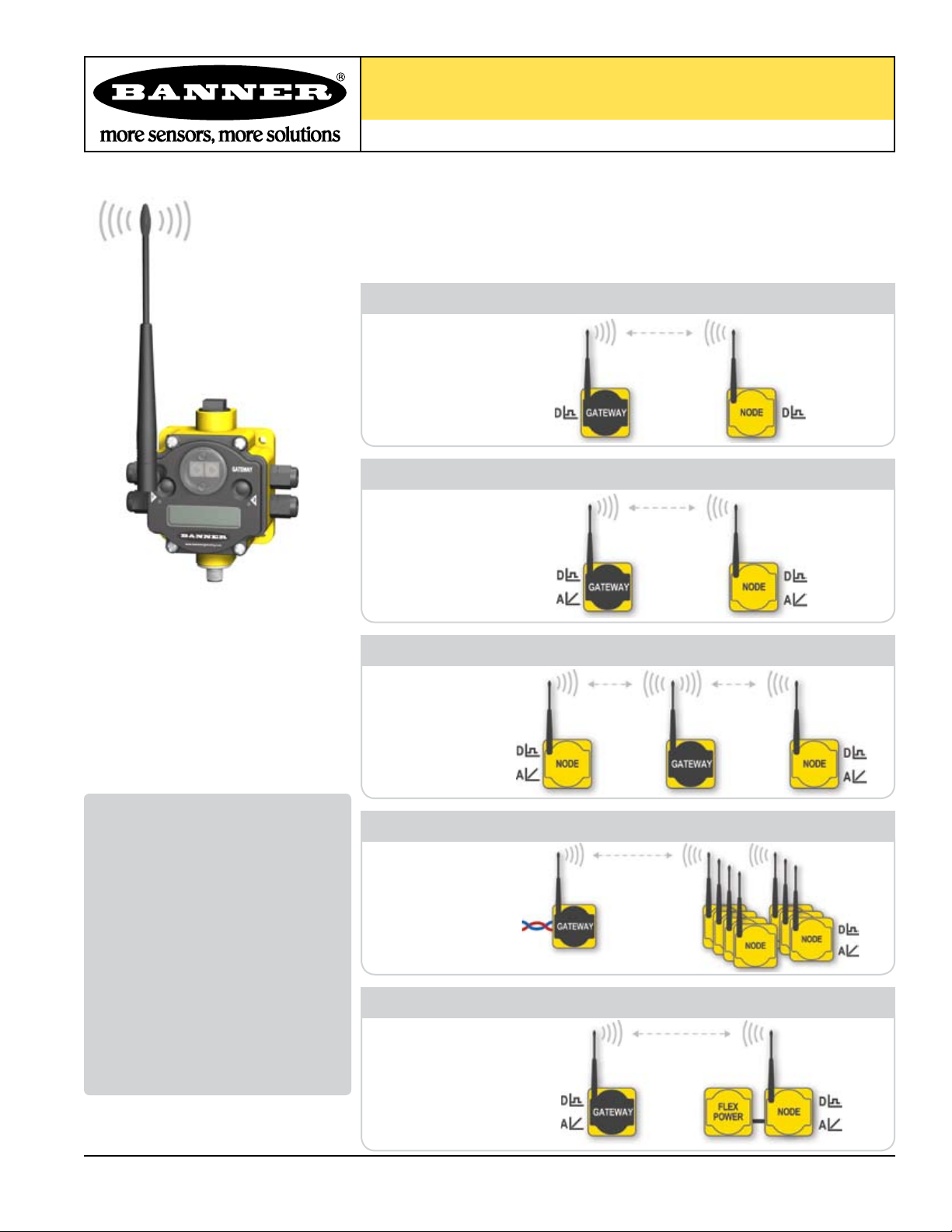
Introducing the Banner DX80 Wireless System
The DX80 wireless system provides continuous monitoring without the burden of wiring or
conduit installation, and can operate independently or in conjunction with a PLC and/or PC
software. Configurations of the DX80 wireless system are shown below.
All Digital
Model Number
DX80K*M6DP1
DX80K*M6DP2
DX80K*M6DP4
DX80K*M6DP7
Digital and Analog
Model Number
DX80K*M6MP1
DX80K*M6MP2
DX80K*M6MP7
Repeater
Model Number
DX80K*R6DP1
DX80K*R6DP2
DX80K*R6DP4
DX80K*R6MP1
DX80K*R6MP2
Table of Contents
Overview .................................................. 1
Setting Up ................................................ 2
Quick Start
STEP 1: Set NID & Device Address . 4
STEP 2: Apply Power (Gateway)... 5
STEP 3: Apply power (Node) .........5
STEP 4: Verify Communications ... 6
STEP 5: SiteSurvey ...................... 7
Host Network ........................................... 8
Product Dimensions ............................... 11
Menu System ........................................... 12
Troubleshooting ....................................... 16
Model Number
DX80K*S6DP
DX80K*S6MP
DX80K*S3PE
DX80K*S3GE
Model Number
*
*
*
*
DX80K*M3PE1
DX80K*M3GE1
DX80K*S3PE
*
Host-Connected
Up to 7 Nodes
FLEX Power
DX81
DX80K*S3GE*
DX80K*R3PE1
DX80K*R3GE1
Printed in USA 09/06 P/N 128185
Battery Module
DX80 Quick Start Guide
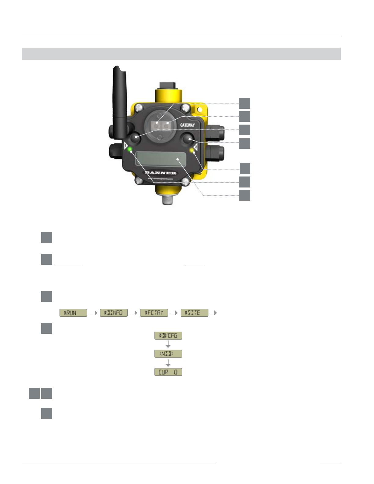
DX80 Gateway and Node Front-Panel Interface
SETTING UP
1
2
3
4
5
6
7
Rotary Switches: Used to set Network ID & Device Address
Rotary Switch 1 (left)
1
Sets the Network ID (NID) to a value from 0 to 15
Rotary Switch 2 (right)
2
On Gateway: Sets Device Address and displays its settings On Node: Sets the Node’s Device Address (1-7)
Push Buttons: Used to navigate the Gateway and Node menus and program device configurations
Push Button 1
3
Single-click to advance across all DX80 menus.
etc.
Push Button 2
4
Single-click to move down interactive menus.
Double-click to move back to top-level menu.
5 6
LED 1 and 2
Provide real-time feedback to the user regarding RF link status, serial communications activity, and Error state.
LCD Display
7
Six-character display provides run mode user information and shows enabled I/O point status. This display allows the user to conduct a
Site Survey (RSSI), assign Network ID, and modify other DX80 configuration parameters without the use of a PC or other external software
interfaces.
etc.
P/N 128185
Banner Engineering Corp. • Minneapolis, MN U.S.A.
2
www. bannerenginee ring.com • Tel: 763.544.3164
SETTING UP
DX80 Quick Start Guide
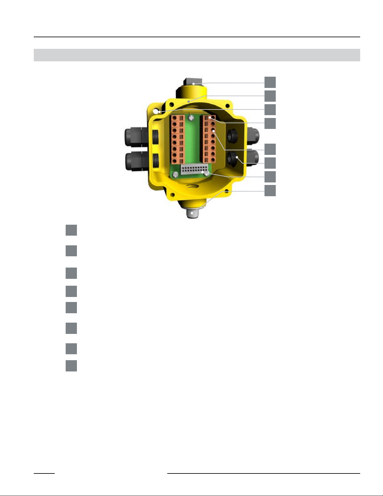
DX80 Gateway and Node Wiring Chamber
1
2
3
4
5
6
7
8
Port, NPT Gland or Plug
1
1/2 NPT threaded port can accept provided plug.
Housing
2
Rugged, industrial DX80 housing is rated IEC IP67
Mounting Hole, #10/M5 Clearance
3
Mounting Holes accept metric M5 or UNC/UNF #10 hardware -- DIN rail mount adapter bracket available
Wiring Terminal Strip
4
Wiring Terminal
5
Wiring terminal is of spring-clip type. Each of the 16 wiring terminals will accept wire sizes: AWG 12-28 or 2.5 mm
Port, PG-7 Gland or Blank
6
PG-7 threaded port can accept provided cable glands or blanks.
Ribbon Connector
7
Ribbon cable connects wiring base to LCD/radio.
5-Pin M12 Euro-style quick-disconnect fitting
8
2
Banner Engineering Corp. • Minneapolis, MN U.S.A.
www. bannerenginee ring.com • Tel: 763.544.3164
3
P/N 128185
DX80 Quick Start Guide
GETTING STARTED – NETWORK SETUP
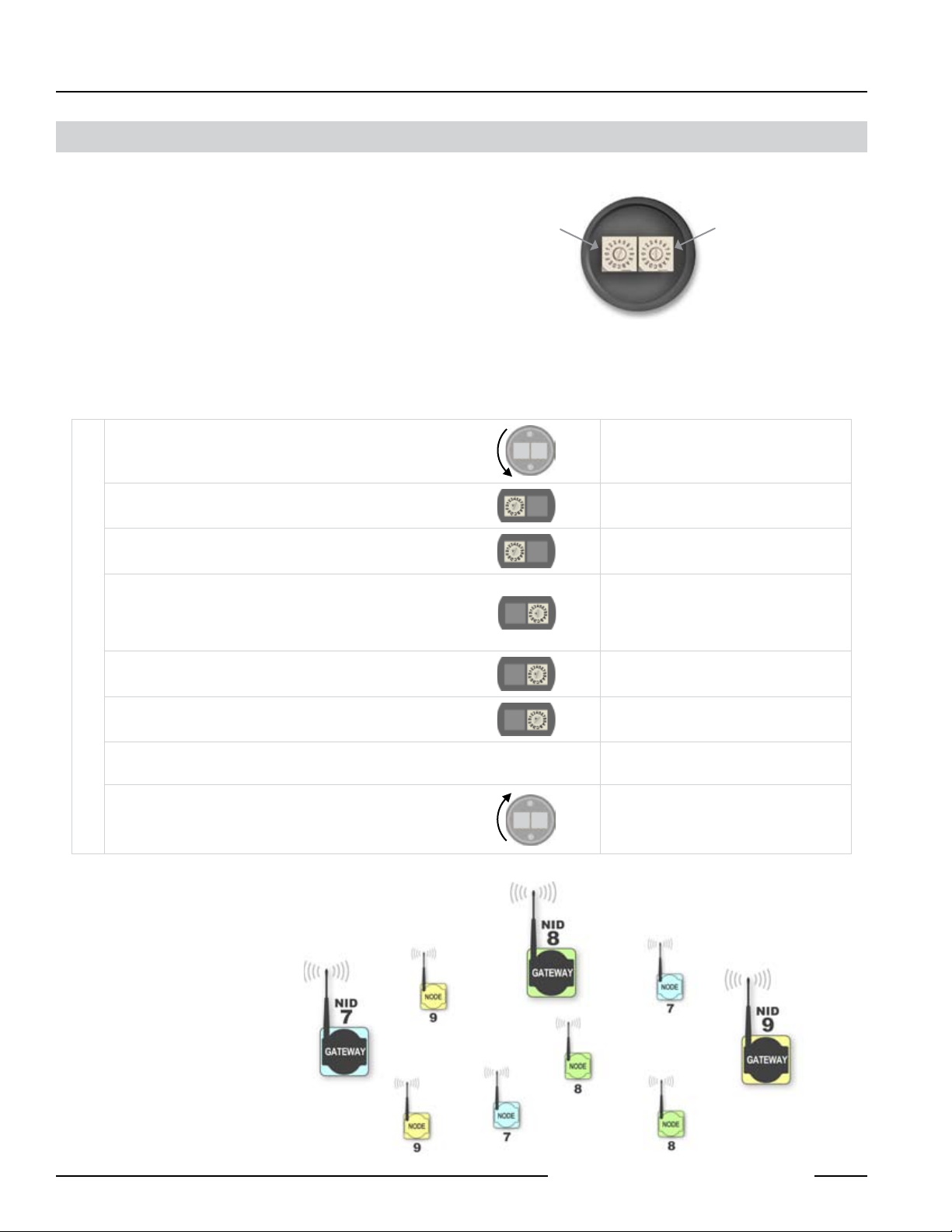
Quick Start: STEP 1
The Banner DX80 wireless system is a network of devices
consisting of a Gateway and Node(s).
The network is defined by the Network ID (NID) assigned
to the Gateway and its Node(s). Additionally, each device
within this common network (NID) must have a unique
Device Address assigned.
Use the Rotary Switches (shown right) to define both the
NID and Device Address for each device. Follow the steps
below to set up your DX80 network.
User Action Display/Status Notes
Remove rotary switch access covers.
On the Gateway, set the Left Rotary Switch to 1.
On all Nodes (within the same network), set the Left
SET NETWORK IDSET DEVICE ADDRESS
Rotary Switch to 1.
On the Gateway, set the Right Rotary Switch to 0.
On the first Node (Device Address = 1), set the Right
Rotary Switch to 1.
Network ID (NID) Device Address
> Set Network ID & Device/Node Address
Rotary Switches on
Gateway & Node
Turn counterclockwise to remove and clockwise
to tighten
The factory default NID setting on all devices is 1
Assign the same NID to all devices within a
single network (0-15). A-F is 10-15 respectively.
A Device Address of 0 on the Gateway will
display settings for the Gateway itself. To view
settings for another device on the network, adjust
the Right Rotary Switch on the Gateway to the
respective Device Address.
On the second Node (Device Address = 2), set the
Right Rotary Switch to 2.
Continue setting the Device Address for each additional
Node using a unique number (..3,4,5).
Install rotary switch access covers.
Multiple Networks:
When more than one network is
operating in the same space, assign
a unique Network ID (NID) to each
network (shown right).
A successful RF link is identified by:
• The Gateway’s LED 1 is Green
• The Node(s) LED 1 is Flashing Green
P/N 128185
Banner Engineering Corp. • Minneapolis, MN U.S.A.
4
www. bannerenginee ring.com • Tel: 763.544.3164
GETTING STARTED – APPLY POWER
DX80 Quick Start Guide
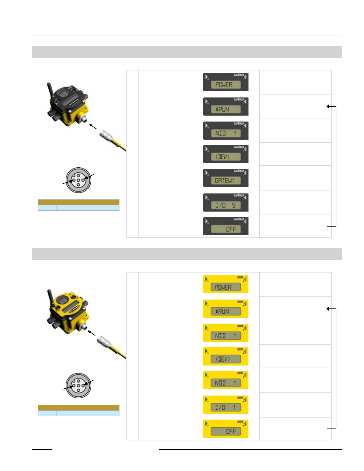
Quick Start: STEP 2
To apply power to the Gateway, connect 10-30V dc cable as shown.
Apply power...
The LCD display shows
the current I/O status of
the Gateway.
3 = BLUE
1 = BROWN
Brown 1 10-30V dc Input
Blue 3 Ground Input
> Apply Power, Gateway
This reading occurs only at
initial application of power to the
Gateway.
The Gateway starts in RUN mode.
Displays current Network ID (NID)
Device is ...
... Gateway (Device Address = 0)
Indicates the current status of the
I/O. The display will cycle through
each I/O point of the device, then
return to *RUN.
repeat
Quick Start: STEP 3
> Apply Power, Node
To apply power to the Node, connect 10-30V dc cable or DX81 Battery Module as shown.
Apply power...
The LCD display shows
the current I/O status of
the Node.
3 = BLUE
1 = BROWN
Brown 1 10-30V dc Input
Blue 3 Ground Input
This reading occurs only at initial
application of power to the Node.
The Node starts in RUN mode.
Displays current Network ID (NID)
Device is ...
... Node 1 (Node Address = 1)
Indicates the current status of the
I/O. The display will cycle through
each I/O point of the device, then
return to *RUN.
Banner Engineering Corp. • Minneapolis, MN U.S.A.
www. bannerenginee ring.com • Tel: 763.544.3164
repeat
5
P/N 128185
DX80 Quick Start Guide
GETTING STARTED – VERIFY COMMUNICATIONS
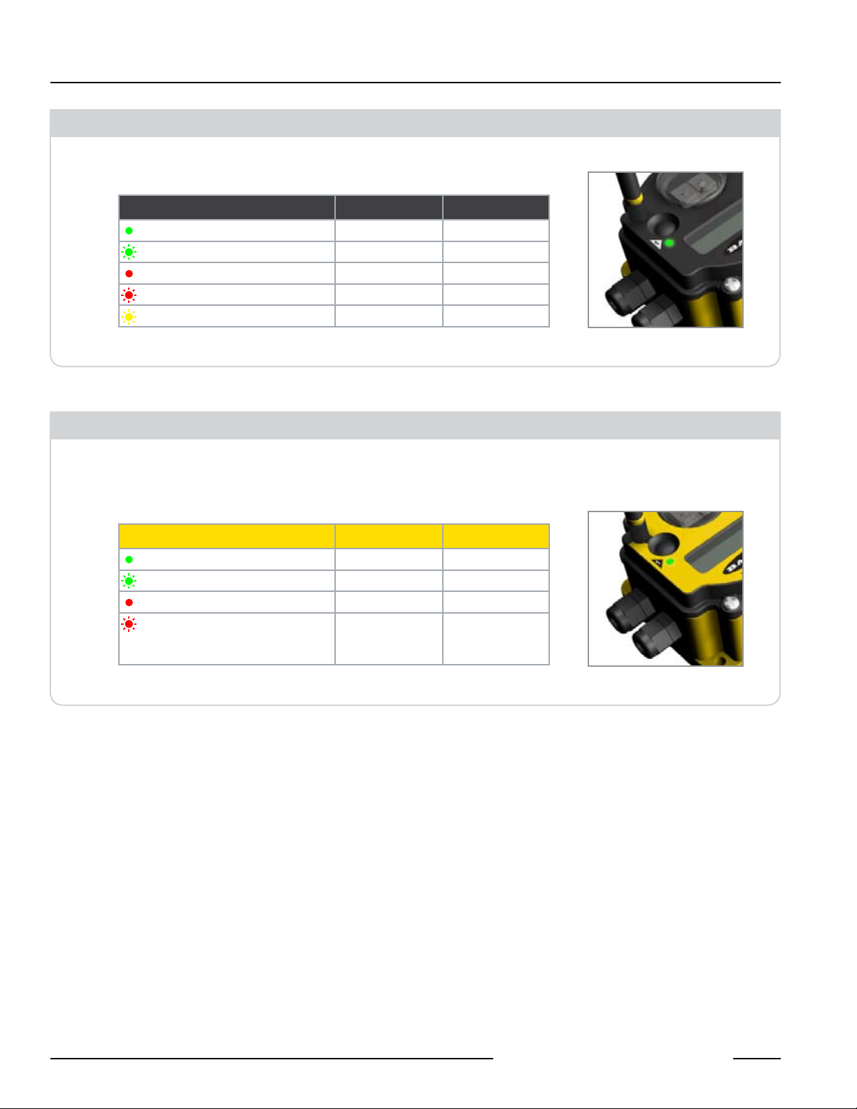
Quick Start: STEP 4
Verify LED 1 is ON Green.
Gateway
Green ON Power ON —
Green FLASHING — —
Red ON System Error RS485 Error
Red FLASHING — RS485 Fault
Yellow FLASHING — RS485 Active
Verify LED 1 is flashing Green. LED 2 is off. Until communication is established with
the Gateway, the Node’s LED 2 flashes Red. When communication is established, the
Node’s LED 1 flashes Green.
LED Status LED 1 LED 2
> Verify Communications, Gateway
> Verify Communications, Node
Node
LED Status LED 1 LED 2
Green ON — —
Green FLASHING RF Link OK —
Red ON System Error System Error
Red FLASHING — No RF Link with
Gateway
(out of sync)
P/N 128185
Banner Engineering Corp. • Minneapolis, MN U.S.A.
6
www. bannerenginee ring.com • Tel: 763.544.3164

GETTING STARTED – SITE SURVEY
DX80 Quick Start Guide
Quick Start: STEP 5
> Site Survey (optional)
A site survey determines the quality of the link between a Gateway and a given Node. The Gateway is used to perform a site survey.
NOTE: The Site Survey should be performed prior to the permanent installation of your network to ensure robust communication.
User Action Display/Status
Notes
Remove Gateway rotary switch access cover.
The Gateway is enabled to read the status
Change right rotary switch setting to 1
Single-click Gateway push button 1
Single-click Gateway push button 1
Single-click Gateway push button 1
SITE SURVEY MENUSURVEY READINGSRETURN TO RUN MODE
Single-click Gateway push button 2
Single-click Gateway push button 2
Examine reception readings (M,R,Y,G) of the Gateway
at various locations
of Node 1 and the display will now scroll
through the Node’s I/O status
Device Information menu
Factory Settings menu
Site Survey menu
Site Survey will be conducted with Node 1
The Gateway analyzes the quality of signal
from the Node by counting the number of
data packets it receives from the Node.
M = Missed packet
R = RED marginal signal,
Y = YELLOW good signal,
G = GREEN excellent signal
Install devices in positions that optimize
the number of YELLOW and GREEN data
packets received.
Double-click Gateway push button 2
Change right rotary switch back to 0 (Gateway)
Double-click Gateway push button 2
Single-click Gateway push button 1
Single-click Gateway push button 1
Single-click Gateway push button 1
Install Gateway rotary switch access cover.
Banner Engineering Corp. • Minneapolis, MN U.S.A.
www. bannerenginee ring.com • Tel: 763.544.3164
End Site Survey
Change the device readings back to the
Gateway
Move back to the top level menu
Return to RUN mode
7
P/N 128185

DX80 Quick Start Guide
GETTING STARTED – HOST NETWORK
Host Network – Gateway
Installing a host-connected network is similar to installing a standard DX80 wireless system, except that all device I/O for the Gateway
and each Node can be accessed by a Modbus RTU Master device via serial RS485. (See pages 4-6 for instruction to Apply Power, Verify
Communications, Conduct a Site Survey.) Follow this procedure if it is necessary to change the Gateway Slave ID, Baud Rate and Parity.
All steps (Power up, Site Survey, Applying Devices) are identical to the stand-alone system procedures, except that the Gateway has
no hard-wired inputs or outputs enabled or linked. Instead, all device I/O of the Gateway and each Node can be accessed by a Modbus
RTU Master device via serial RS485. In order to accomplish this, you may first need to configure several system-level communications
parameters on the DX80 Gateway (in addition to the serial hookups shown below).
Parameter Description
Slave ID (default = 1)
Baud Rate (default = 19200)
Parity (default = none)
Defines the slave number (1) for the serial
Modbus RTU protocol.
Defines communication data rate (19.2, 38.4 or
9.6 kbps) between the Gateway and the Host
through the serial interface.
Defines serial parity (none, even, or odd)
between Gateway and Host.
4 = BLACK
1 = BROWN
Wiring: 5-pin Euro pinouts for 485+, 485- and
Comms ground
Brown 1 10-30V dc Input
White 2 RS 485 / D1 / B /+
Blue 3 Ground Input
Black 4 RS485 / D0 / A / -
Grey 5 Comms Gnd
5 = GREY
3 = BLUE
2 = WHITE
P/N 128185
Banner Engineering Corp. • Minneapolis, MN U.S.A.
8
www. bannerenginee ring.com • Tel: 763.544.3164

GETTING STARTED – HOST NETWORK
DX80 Quick Start Guide
Host Network – Gateway (cont.)
Setting the Slave ID
Similar to Network ID, the Slave ID parameter can be changed in the Device Configuration (*DVCFG) system menu option. Follow the Top
Level System Menu through *DVCFG to the Slave ID (SLID) parameter. The LCD will display an alternating Current value and New value
for the parameter.
User Action Display/Status Notes
To navigate to the *DVCFG
On the Gateway, move to the “Device Configuration” menu
Single-click Gateway push button 2
(Device Configuration)
menu, see page 12.
Single-click Gateway push button 1
Single-click Gateway push button 2
SET SLAVE ID
Set rotary switches to the desired new Slave ID
Single-click Gateway push button 2
Single-click Gateway push button 1
Single-click Gateway push button 2
Single-click Gateway push button 1
SET BAUD RATESET PARITY
Single-click Gateway push button 2
Single-click Gateway push button 1
Single-click Gateway push button 2
Single-click Gateway push button 1
Moves to the Slave ID field,
default value is 1
The new Slave ID is defined
by the current position of the
rotary switches.
Select between 01 to 99
Slave ID is saved
Moves to the BAUD rate
field
Options are 9600, 19200,
38400, default is 19200
Baud rate is saved.
Moves to the Parity field
Options are NONE, EVEN,
ODD, default is NONE
Single-click Gateway push button 2
Double-click Gateway push button 2
Click Gateway push button 1 through to *RUN
Adjust Left rotary switch back to NID value
Banner Engineering Corp. • Minneapolis, MN U.S.A.
www. bannerenginee ring.com • Tel: 763.544.3164
Parity setting is saved.
Returns to Device
Configuration menu
9
P/N 128185

DX80 Quick Start Guide
A wireless network can be hindered by
radio interference and obstructions in the
path between a receiver and transmitter.
To achieve the best radio performance,
installation locations for Gateways and
Nodes should be carefully considered.
DX80 QUICK TIPS
Clear Communication Paths
Increase Height of DX80 Units
The external antenna should be verticallyoriented for optimal RF communication.
In addition, consider the height of DX80
position to improve reception levels.
P/N 128185
10
Banner Engineering Corp. • Minneapolis, MN U.S.A.
www. bannerenginee ring.com • Tel: 763.544.3164

DIMENSIONS
DX80 Quick Start Guide
DX80 Gateway & Node Dimensions
65.0 mm
(2.56˝)
65.0 mm
(2.56˝)
59.3 mm
(2.33˝)
TOP VIEW
80.3 mm
(3.16˝)
126.7 mm
(4.99˝)
SIDE VIEW
80.8 mm
(3.18˝)
121.8 mm
(4.79˝)
BOTTOM VIEW
Banner Engineering Corp. • Minneapolis, MN U.S.A.
www. bannerenginee ring.com • Tel: 763.544.3164
11
P/N 128185

DX80 Quick Start Guide
CONFIGURATION
DX80 Gateway Setup Menu
When power is applied, the DX80 immediately enters RUN state (Gateway or Node). Run state is the normal operating mode for all devices
on the wireless network.
†
†
If the user gets lost navigating the
menu system, they can double-click
Push Button 2 twice to return to the
top level menu.
Navigating the menu:
= Top level
*
< > = Sub-menu item
No characters = Value of
previous item
P/N 128185
12
Banner Engineering Corp. • Minneapolis, MN U.S.A.
www. bannerenginee ring.com • Tel: 763.544.3164

CONFIGURATION
DX80 Quick Start Guide
DX80 Node Setup Menu
When power is applied, the DX80 immediately enters RUN mode (Gateway or Node). RUN mode is the normal operating mode for all
devices on the wireless network.
†
†
If the user gets lost navigating the
menu system, they can double-click
Push Button 2 twice to return to the
top level menu.
Navigating the menu:
= Top level
*
< > = Sub-menu item
No characters = Value of
previous item
Node LCD Timeout: Press any
button to refresh the display if the
Node has entered this energysaving mode.
Banner Engineering Corp. • Minneapolis, MN U.S.A.
www. bannerenginee ring.com • Tel: 763.544.3164
13
P/N 128185

DX80 Quick Start Guide
TROUBLESHOOTING
RF Link Time-out & Recovery
Banner DX80 wireless devices employ a deterministic link time-out method to address RF link interruption or failure. As soon as a specific
Node/Gateway RF link times out, all pertinent wired outputs are de-energized until the link is recovered (see kit-specific Supplemental Sheet
for more information). Through this process, users of Banner wireless networks can be assured that disruptions in the communications link
will result in predictable system behavior.
Link time-out utilizes a fully-acknowledged polling method to determine RF link status of each Node on the network. If after a prescribed
number of sequential polling cycles the Node does not acknowledge a message, the Gateway considers the link with the Node to be timed
out. LCD displays on both the Node and Gateway will show *ERROR. Following a time-out, the Node de-energizes outputs; the Gateway (or
Repeater Node, if applicable) sets all outputs linked to the Node in question to a de-energized state, as well.
Once a link has been faulted, the Gateway must receive a number of good packets from the Node in question (with some hysteresis to
prevent link “toggling”) for the link to be reinstated. If the DX80 network is not Host-connected (RS485 serial access not enabled), outputs
are restored to current values when the link is recovered.
P/N 128185
Link between Gateway and Node 1 timed out.
Link between Gateway and Node 1 recovered.
Banner Engineering Corp. • Minneapolis, MN U.S.A.
14
www. bannerenginee ring.com • Tel: 763.544.3164

TROUBLESHOOTING
DX80 Quick Start Guide
RF Link Time-out & Recovery – Host-connected
In a Host-connected DX80 system, a link time-out will result in an error code (53 or 0x35xx) being placed in the Node-specific DEVICE
MESSAGE Modbus register (Node 1 = Register 24, Node 2 = Register 40, etc.).
In order for the RF link to be reinstated, the Host must send a control message to clear the device error message. Any Node output
registers will be re-populated by the latest Gateway register map.
Link between Gateway and Node 1 timed out.
Link between Gateway and Node 1 recovered.
It is the responsibility of the Host to handle Node device error messages. This will result in outputs being reinstated.
*
Banner Engineering Corp. • Minneapolis, MN U.S.A.
www. bannerenginee ring.com • Tel: 763.544.3164
15
P/N 128185

DX80 Quick Start Guide
TROUBLESHOOTING
Troubleshooting
A wireless network can be hindered by radio interference as well as obstructions in the path of the receiver and transmitter. To achieve the best radio
performance possible, the installation locations for Gateways and Nodes should be carefully considered. In general, the need for a clear path becomes
greater as the transmission distance increases. Use Site Survey (RSSI) to confirm signal quality before fixing devices for permanent installation.
Problem Description
No LEDs, No LCD
display
Node flashes the red
LED (no sync)
Marginal Site
Survey (RSSI)
results
No communications
with the DX80
Gateway using
RS485
DX80 Display shows
*ERROR
Particular inputs and/
or outputs are not
working
Possible Solutions
Basic power–up issues
DX80 devices should immediately display ‘POWER’ on the LCD for the first 5-10 seconds after power is applied. A DX80
•
Gateway will always have a green LED on when power is connected. DX80 Node devices will flash a red LED every 3
seconds or a green LED every second depending upon the RF Link status.
Battery devices can be put into a power down mode using button 1 on the front panel. To put a battery device into power
•
down mode, hold button 1 for 3-5 seconds. To make a battery device come out of power down mode, hold button 1 for 3-5
seconds.
Recheck power connections and power requirements. Line powered devices require 10-30V DC. The DX81 Battery Module
•
provides 3.6V DC.
DX80 devices will not Synchronize
There are two things that MUST be set on every Node device to make it synchronize with the Gateway device:
•
1) The Network ID on the Node must match the Gateway Network ID. (0-15).
2) Each node must have the rotary switches set to a unique number (1-15).
Refer to “Getting Started – Multiple Networks, Setting Network ID”
•
If the DX80 Gateway & Node are less than 2 meters apart the devices may not communicate properly (radios may saturate).
•
The Gateway & Node may be too far apart to achieve sync – consult factory for options.
•
Qualified antenna should be placed on both the Gateway and Node device.
•
After system parameter changes it is a good idea to cycle power to cause a resyncing of the devices.
•
If a Node device goes out of sync it is programmed to try to acquire sync for 5 seconds and then sleep for 15 seconds.
•
Synchronizing may require up to 20 seconds.
Recycle power on the Gateway & Node devices.
•
Site survey (RSSI) returns > 30 MISSED packets
If the distance between devices is greater than about 5,000 meters (3 miles) line of sight *OR* objects such as trees or
•
man-made obstructions interfere with the path, and the MISSED packet count exceeds 30 per 100 packets, the following
steps should be considered:
DX80 units should be raised to a higher elevation – either by physically moving the devices, or installing the antenna(s)
•
remotely at a higher position.
Use high-gain antenna(s) such as Yagi and/or Omni (see Accessories).
•
Decrease the distance between devices.
•
DX80 Gateway will not talk with the host system
Default communications parameters for the RS485 are: 1 start bit, 8 data bits, no parity, 1 stop bit and 19.2k baud. The
•
DX80 Gateway uses Modbus RTU protocol for all communications. The supported Modbus function codes are 3, 6, and 16.
Make sure the DX80 model supports RS485 serial communications.
•
Make sure the Slave ID is set properly for the bus environment. Factory default Slave ID = 1.
•
Factory default for the Modbus timeout is set to 4 seconds (for Modbus kits only). If you are using this feature make sure the
•
time is properly set.
RS485 termination or biasing is not supplied on the DX80 Gateway and should be provided externally to the DX80.
•
(Termination is not required by the DX80 Gateway, proper biasing of the serial lines is required.)
RF link time-out and recovery
The Gateway utilizes fully-acknowledged polling to ensure each Node RF link is robust. Consequently, if after a prescribed
•
number of sequential polling cycles are not acknowledged by a Node, the Gateway considers the particular link with that
Node to be timed out. All outputs on the Node in question will be set to “OFF” (discrete) or “0” (analog, regardless of type).
If the Node’s RF link is recovered and the Gateway can determine that enough acknowledged polling messages have been
•
accumulated, then the link is reinstated and outputs are restored to the current values.
I/O functionality
Use manual scrolling mode within *RUN to freeze the I/O status on the LCD display for the device in question. Verify that
•
when the input device changes state or changes value, the LCD mirrors the behavior.
Also verify that the LCD on the output side mirrors the linked input’s behavior. If the input device state, LCD on origination
•
DX80, and LCD on destination DX80 all behave exactly the same, there may be a wiring issue or an interfacing problem.
Consult factory.
P/N 128185
16
Banner Engineering Corp. • Minneapolis, MN U.S.A.
www. bannerenginee ring.com • Tel: 763.544.3164

COMPLIANCE
DX80 Quick Start Guide
Agency Certification
FCC Certification
The DX80 Module complies with Part 15 of the FCC rules and regulations.
FCC ID: UE300DX80-2400 This device complies with Part 15 of the FCC Rules. Operation is subject to the following
two conditions: (1) this device may not cause harmful interference and (2) this device must accept any interference received,
including interference that may cause undesired operation.
FCC Notices
IMPORTANT: The DX80 Modules have been certified by the FCC for use with other products without any further
certification (as per FCC section 2.1091). Changes or modifications not expressly approved by the manufacturer could void the
user’s authority to operate the equipment.
IMPORTANT: The DX80 Modules have been certified for fixed base station and mobile applications. If modules will be
used for portable applications, the device must undergo SAR testing.
IMPORTANT: If integrated into another product, the FCC ID label must be visible through a window on the final device or
it must be visible when an access panel, door or cover is easily removed. If not, a second label must be placed on the outside
of the final device that contains the following text: Contains FCC ID:UE300DX80-2400
NOTE:
This equipment has been tested and found to comply with the limits for a Class B digital device, pursuant to Part 15 of the
FCC Rules. These limits are designed to provide reasonable protection against harmful interference in a residential installation.
This equipment generates uses and can radiate radio frequency energy and, if not installed and used in accordance with the
instructions, may cause harmful interference to radio communications. However, there is no guarantee that interference will
not occur in a particular installation. If this equipment does cause harmful interference to radio or television reception, which
can be determined by turning the equipment off and on, the user is encouraged to try to correct the interference by one or more
of the following measures:
• Reorient or relocate the receiving antenna.
• Increase the separation between the equipment and receiving module.
• Connect the equipment into an outlet on a circuit different from that to which the receiving module is
connected.
• Consult the dealer or an experienced radio/TV technician for help.
Antenna Warning WARNING: This device has been tested with Reverse Polarity SMA connectors with the antennas listed
in Table 1 Appendix A. When integrated into OEM products, fixed antennas require installation preventing end-users from
replacing them with non-approved antennas. Antennas not listed in the tables must be tested to comply with FCC Section
15.203 (unique antenna connectors) and Section 15.247 (emissions).
FCC-Approved Antennas
WARNING: This equipment is approved only for mobile and base station transmitting devices. Antenna(s) used for this
transmitter must be installed to provide a separation distance of at least 20 cm from all persons and must not be co-located or
operating in conjunction with any other antenna or transmitter.
DX80 Module may be used only with Approved Antennas that have been tested with this module.
Part Number Antenna Type Maximum Gain
— Integral antenna Unity gain
TBD 1/2 wave dipole ≤2 dBi
TBD Collinear ≤5 dBi
TBD
Banner Engineering Corp. • Minneapolis, MN U.S.A.
www. bannerenginee ring.com • Tel: 763.544.3164
Coaxial ≤7 dBi
Table 1. Type certified Antenna
17
P/N 128185

DX80 Quick Start Guide
Notes
P/N 128185
P/N 128185
18
18
Banner Engineering Corp. • Minneapolis, MN U.S.A.
Banner Engineering Corp. • Minneapolis, MN U.S.A.
www. bannerenginee ring.com • Tel: 763.544.3164
www. bannerenginee ring.com • Tel: 763.544.3164

DX80 Quick Start Guide
Notes
Banner Engineering Corp. • Minneapolis, MN U.S.A.
Banner Engineering Corp. • Minneapolis, MN U.S.A.
www. bannerenginee ring.com • Tel: 763.544.3164
www. bannerenginee ring.com • Tel: 763.544.3164
19
19
P/N 128185
P/N 128185

WARRANTY: Banner Engineering Corp. warrants its products to be free from defects for one year.
Banner Engineering Corp. will repair or replace, free of charge, any product of its manufacture
found to be defective at the time it is returned to the factory during the warranty period. This
warranty does not cover damage or liability for the improper application of Banner products. This
warranty is in lieu of any other warranty either expressed or implied.
Banner Engineering Corp., 9714 Tenth Ave. No., Minneapolis, MN 55441 • Phone: 763.544.3164 • www.bannerengineering.com • Email: sensors@bannerengineering.com
 Loading...