

Banner WLS27CWGRXX3 0570 HS24Q, WLS27XWGRXX3 1130 HS24Q, WLS27XGYRXX3 0570 DS24Q, WLS27CWGRYB5 1130 DS24Q, WLS27XWGRXX3 0570 HS24Q Quick Start Manual
...Page 1
WLS27
ConnectorWindow
Lighted
Length (mm)
Colors 1-5 and ControlCascadableFamily
C = Cascadable
X = Non-cascadable
WGRXX3 = White, Green, Red with override control
WYRXX3 = White, Yellow, Red with override control
GYRXX3 = Green, Yellow, Red with override control
WGRYB5 = White, Green, Red, Yellow, Blue with binary control
WGRXX6 = White, Green, Red with I/O Block control
WYRXX6 = White, Yellow, Red with I/O Block control
GYRXX6 = Green, Yellow, Red with I/O Block control
0285
0570
0850
1130
D = Diffused
Q = Integral 4-pin M12 QD
(mating cordset required)
X
WGRXX3 0285 D
Q
Construction
S
S = Sealed
Voltage
24
24 = 24V dc
H = Heavy Diffused
1
4
3
2
2
3
4
1
WLS27 Multicolor LED Strip Light with EZ-
201895
STATUS
™
Quick Start Guide
This guide is designed to help you set up and install the WLS27 Multicolor LED Strip Light. For complete information on programming, performance,
troubleshooting, dimensions, and accessories, please refer to the Instruction Manual at
the Instruction Manual. Use of this document assumes familiarity with pertinent industry standards and practices.
Models
www.bannerengineering.com
. Search for p/n 201896 to view
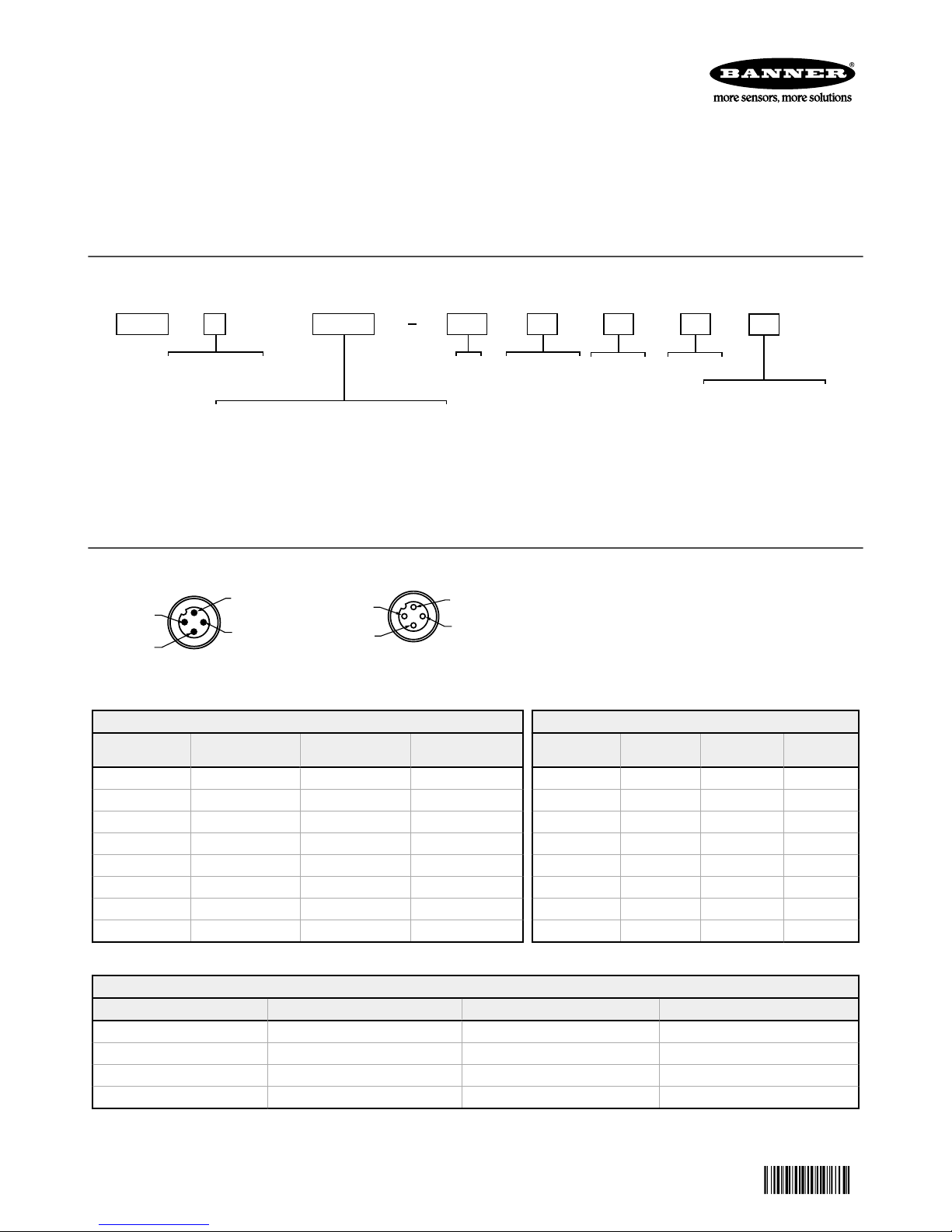
Wiring Diagrams
Male
3 Color Override Control
Input 1: Pin 1
Brown Wire
— — — Light OFF
+24 V dc — — Color 1 ON
— +24 V dc — Color 2 ON
+24 V dc +24 V dc — Color 2 ON
— — +24 V dc Color 3 ON
+24 V dc — +24 V dc Color 3 ON
— +24 V dc +24 V dc Color 3 ON
+24 V dc +24 V dc +24 V dc Color 3 ON
3 Color I/O Block Control
Input 1: Pin 1 Brown Wire Input 2: Pin 4 Black Wire Input 3: Pin 2 White Wire LED Color
Original Document
201895 Rev. C
(Color 3 overrides Colors 1 and 2, Color 2 overrides Color 1)
Input 2: Pin 4 Black
Wire
(Input 1 is always ON through the block)
+24 V dc — — Light OFF
+24 V dc +24 V dc — Color 1 ON
+24 V dc — +24 V dc Color 2 ON
+24 V dc +24 V dc +24 V dc Color 3 ON
Input 3: Pin 2 White
Wire
Female
LED Color
18 June 2018
Key
Pin 1 Brown: Input 1
Pin 2 White: Input 3
Pin 3 Blue: DC Common
Pin 4 Black: Input 2
5 Color Binary Control
Input 1: Pin 1
Brown Wire
— — — Light OFF
+24 V dc — — Color 1 ON
— +24 V dc — Color 2 ON
— — +24 V dc Color 3 ON
+24 V dc +24 V dc — Color 4 ON
+24 V dc — +24 V dc Color 5 ON
— +24 V dc +24 V dc Light OFF
+24 V dc +24 V dc +24 V dc Light OFF
(Binary input state controls color)
Input 2: Pin 4
Black Wire
Input 3: Pin 2
White Wire
LED Color
Page 2

D
16.8
[.66]
17.6
[.69]
27.0
[1.06]
17.6
[.69]
16.8
[.66]
M12 X 1
L1
L2
L3
27.0
[1.06]
16.8
[.66]
17.6
[.69]
16.8
[.66]
17.6
[.69]
M12 X 1
M12 X 1
L4
WLS27 Multicolor LED Strip Light with EZ-STATUS
Specifications
™
Supply Voltage
24 V dc (+ 20% / - 10%)
Use only with suitable Class 2 power supply (UL) or a SELV power supply (CE)
Lighted Length Typical Current (A) at 25° C1Maximum Current (A)
285 mm 0.315 0.400
570 mm 0.630 0.800
850 mm 0.945 1.200
1130 mm 1.260 1.600
Supply Protection Circuitry
Protected against reverse polarity and transient voltages
Application Notes
When connecting cascadable lights in series it is important not to exceed maximum
current limitations:
Maximum length of light at 24 V dc: 3.0 m (9.8 ft)
Do not spray cable with high-pressure sprayer, or cable damage will result.
Dimensions
Mounting
Bracket LMBWLS27EC included (2 for lights up to 570 mm or 3 for lights 850 mm and
longer)
Construction
Clear anodized aluminum inner housing and FDA-grade copolyester outer housing
Connections
Integral 4-pin M12/Euro-style quick disconnect
Environmental Rating
Rated IEC IP66, IEC IP67, and DIN IP69K, per
Vibration and Mechanical Shock
Vibration: 10 Hz to 55 Hz, 1.0 mm peak-to-peak amplitude per IEC 60068-2-6
Shock: 15G 11 ms duration, half sine wave per IEC 60068-2-27
Operating Temperature
–40 °C to +50 °C (–40 °F to +122 °F)
Storage Temperature: –40 °C to +70 °C (–40 °F to +158 °F)
Certifications
Quick Disconnect Models
Cascade Models
Models L1 L2 L3 L4
WLS27..0285.. 286 mm (11.3 in) 330 (13 in) 349.5 mm (13.8 in) 358 mm (14.1 in)
WLS27..0570.. 569 mm (22.4 in) 612 mm (24.1 in) 631.5 mm (24.9 in) 640 mm (25.2 in)
WLS27..0850.. 849 mm (33.4 in) 893 mm (35.2 in) 912.5 mm (35.9 in) 921 mm (36.2 in)
WLS27..1130.. 1120 mm (44.1 in) 1164 mm (45.8 in) 1183.5 mm (46.4 in) 1192 mm (46.9 in)
Banner Engineering Corp. Limited Warranty
Banner Engineering Corp. warrants its products to be free from defects in material and workmanship for one year following the date of shipment. Banner Engineering Corp. will repair or replace, free of charge,
any product of its manufacture which, at the time it is returned to the factory, is found to have been defective during the warranty period. This warranty does not cover damage or liability for misuse, abuse, or
the improper application or installation of the Banner product.
THIS LIMITED WARRANTY IS EXCLUSIVE AND IN LIEU OF ALL OTHER WARRANTIES WHETHER EXPRESS OR IMPLIED (INCLUDING, WITHOUT LIMITATION, ANY WARRANTY OF MERCHANTABILITY OR
FITNESS FOR A PARTICULAR PURPOSE), AND WHETHER ARISING UNDER COURSE OF PERFORMANCE, COURSE OF DEALING OR TRADE USAGE.
This Warranty is exclusive and limited to repair or, at the discretion of Banner Engineering Corp., replacement. IN NO EVENT SHALL BANNER ENGINEERING CORP. BE LIABLE TO BUYER OR ANY OTHER
PERSON OR ENTITY FOR ANY EXTRA COSTS, EXPENSES, LOSSES, LOSS OF PROFITS, OR ANY INCIDENTAL, CONSEQUENTIAL OR SPECIAL DAMAGES RESULTING FROM ANY PRODUCT DEFECT OR
FROM THE USE OR INABILITY TO USE THE PRODUCT, WHETHER ARISING IN CONTRACT OR WARRANTY, STATUTE, TORT, STRICT LIABILITY, NEGLIGENCE, OR OTHERWISE.
Banner Engineering Corp. reserves the right to change, modify or improve the design of the product without assuming any obligations or liabilities relating to any product previously manufactured by Banner
Engineering Corp. Any misuse, abuse, or improper application or installation of this product or use of the product for personal protection applications when the product is identified as not intended for such
purposes will void the product warranty. Any modifications to this product without prior express approval by Banner Engineering Corp will void the product warranties. All specifications published in this
document are subject to change; Banner reserves the right to modify product specifications or update documentation at any time. Specifications and product information in English supersede that which is
provided in any other language. For the most recent version of any documentation, refer to:
www.bannerengineering.com
.
1
Values shown at 25 °C - current and lumen values decrease 0.4% per 1 °C from ambient. For example, a 1130 mm unit will have a maximum current of 1.600 A at -40 °C and 1.134 A at +50 °C.
©
Banner Engineering Corp. All rights reserved
 Loading...