

Page 1
P
WORLD-BEAM QS18
63908
Datasheet
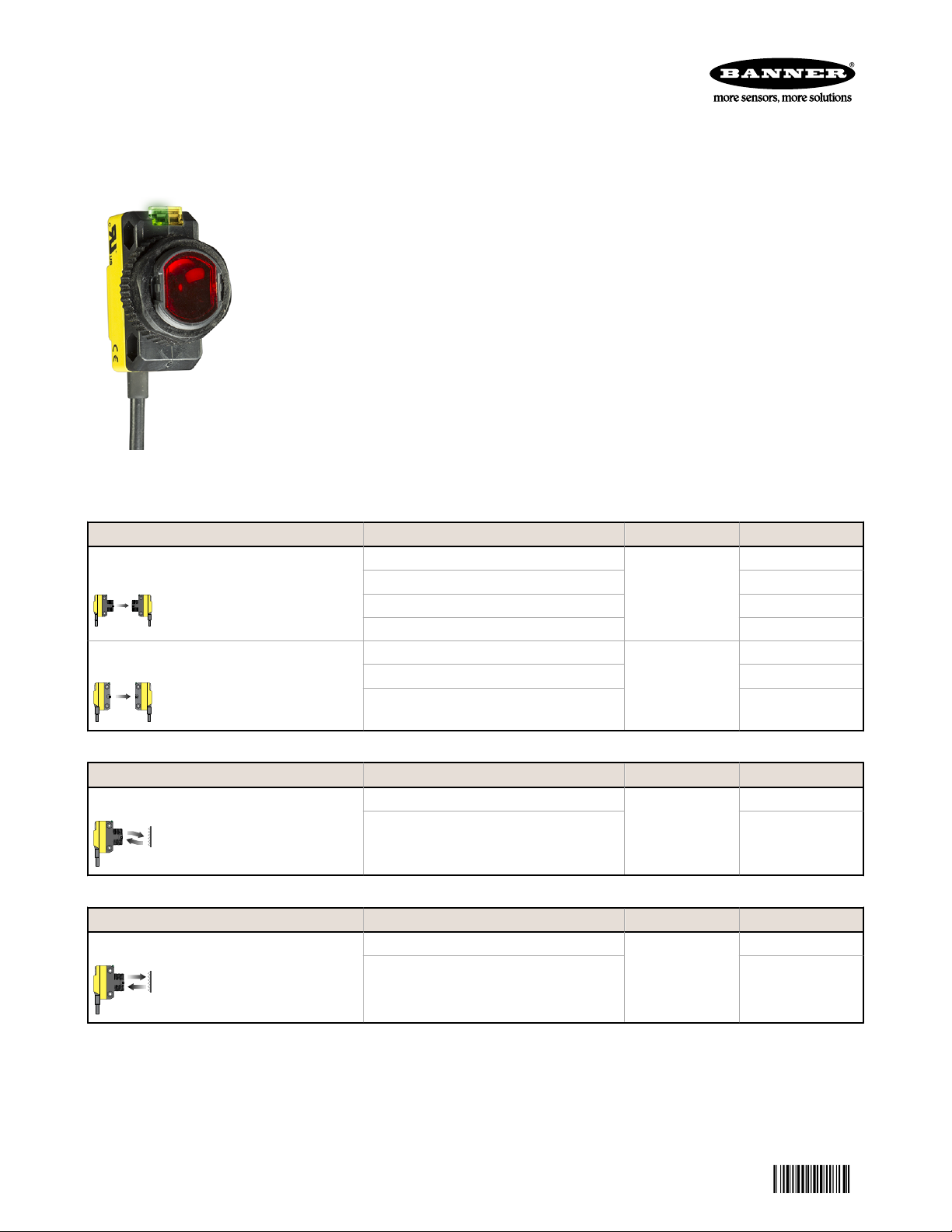
Miniature self-contained photoelectric sensors in universal housing
• Easily fits (or retrofits) almost any mounting situation
• Exceptional optical performance, comparable to larger “MINI-style” or barrel
sensors
• 10 to 30 V dc operation, with complementary (SPDT) NPN or PNP outputs,
depending on model
• Bright LED operating status indicators are visible from 360°
• Rugged sealed housing, protected circuitry
• Models available with or without 18 mm threaded “nose”
• Less than 1 millisecond output response for excellent sensing repeatability
• Choose 2 m (6.5 ft) or 9 m (30 ft) cable or 150 mm (6 inch) Pico-style pigtail QD
To order the 9 m (30 ft) cable model, add suffix "W/30" to the cabled model number.
QD Models. For 4-pin integral Euro-style QD, add suffix “Q8” (e.g., QS186EQ8). For 4-pin
integral Pico-style QD, add suffix “Q7” (e.g., QS186EQ7). For 4-pin 150 mm (6") Eurostyle pigtail, add suffix “Q5” (e.g., QS186EQ5). For 4-pin 150 mm (6") Pico-style pigtail,
add suffix “Q” (e.g., QS186EQ).
Opposed Mode Model Range Output
Effective beam: 13 mm (0.5 inch)
Effective beam: 13 mm (0.5 inch)
Polarized Retroreflective Mode Model Range Output
630 nm Visible Red
Retroreflective Mode Model Range Output
628 nm Visible Red QS18VN6LV
QS186EV (624 nm Visible Red)
QS186E (940 nm Infrared) N/A
QS18VN6R NPN
QS18VP6R PNP
QS186EB (940 nm Infrared)
QS18VN6RB NPN
QS18VP6RB PNP
QS18VN6LP
QS18VP6LP PNP
QS18VP6LV PNP
20 m (66 ft)
3 m (10 ft)
3.5 m (12 ft)
6.5 m (21 ft)
N/A
N/A
NPN
NPN
Original Document
63908 Rev. H
4 March 2014
Page 2
WORLD-BEAM QS18
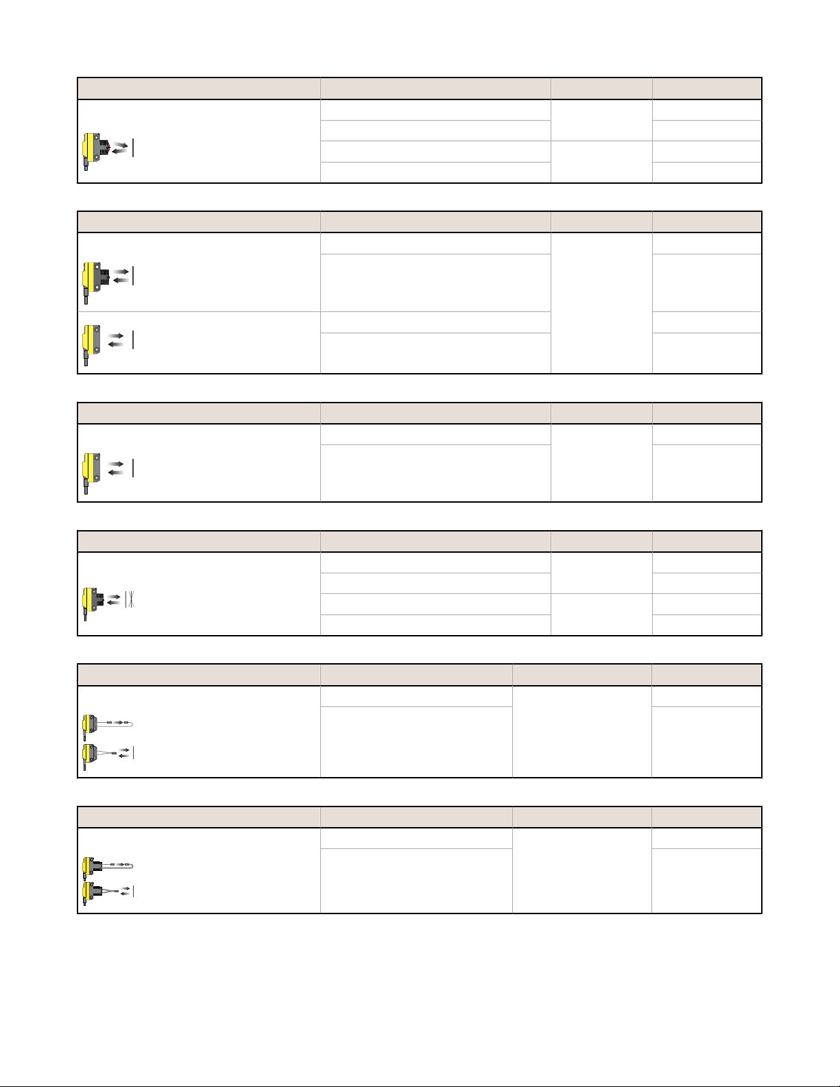
Convergent Mode Model Range Output
630 nm Visible Red
QS18VN6CV15
QS18VP6CV15 PNP
QS18VN6CV45
QS18VP6CV45 PNP
16 mm (0.63 ft)
43 mm (1.7
inches)
NPN
NPN
Diffuse Mode Model Range Output
940 nm Infrared QS18VN6D
NPN
QS18VP6D PNP
450 mm (18
inches)
QS18VN6DB (Diffuse, wide) NPN
QS18VP6DB (Diffuse, wide) PNP
Divergent Mode Model Range Output
940 nm Infrared QS18VN6W
NPN
100 mm (4
QS18VP6W PNP
inches)
Fixed Field Mode Model Range Output
660 nm Visible Red
QS18VN6FF50
QS18VP6FF50 PNP
QS18VN6FF100
QS18VP6FF100 PNP
50 mm (2 inches)
100 mm (4
inches)
NPN
NPN
Plastic Fiber Optic Mode Model Range Output
660 nm Visible Red QS18VN6FP
NPN
Range varies by sensing
QS18VP6FP PNP
mode and fiber optics
used
Glass Fiber Optic Mode Model Range Output
940 nm Infrared QS18VN6F
NPN
Range varies by sensing
QS18VP6F PNP
mode and fiber optics
used
2 www.bannerengineering.com - tel: 763-544-3164 P/N 63908 Rev. H
Page 3
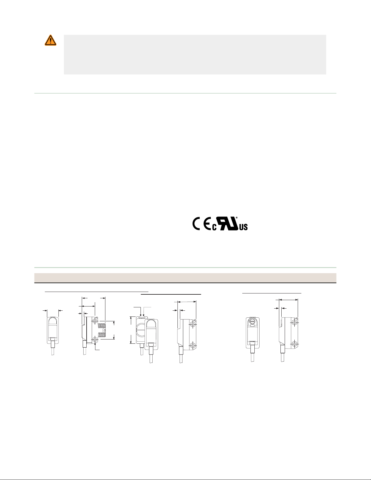
Model Suffix E, EV, R, and FF
15.0 mm
(0.59")
31.0 mm
(1.22")
3.0 mm
(0.12")
17.1 mm
(0.67")
24.1 mm
(0.95")
35.0 mm
(1.38")
Yellow
LED
Green
LED
Ø3.3 mm (0.13")
Max. torque 0.6 Nm (5 in-lbs)
Model Suffix EB, RB
3.0 mm
(0.12")
21.1 mm
(0.82")
Model Suffix DB, W
3.0 mm
(0.12")
21.1 mm
(0.82")
WORLD-BEAM QS18
WARNING: Not To Be Used for Personnel Protection
Never use this device as a sensing device for personnel protection. Doing so could lead to
serious injury or death. This device does not include the self-checking redundant circuitry necessary
to allow its use in personnel safety applications. A sensor failure or malfunction can cause either an
energized or de-energized sensor output condition.
Specifications
Supply Voltage
10 to 30 V dc (10% maximum ripple) at less than 25 mA, exclusive of
load;
Protected against reverse polarity and transient voltages
Repeatability
Opposed Mode: 100 microseconds
FF Mode: 160 microseconds
All others: 150 microseconds
Adjustments
Glass Fiber Optic, Plastic Fiber Optic, Convergent, Diffuse, and
Retroreflective mode models (only): Single-turn sensitivity (Gain)
adjustment potentiometer
Indicators
2 LED indicators on sensor top:
Green solid: Power on
Amber solid: Light sensed
Green flashing: Output overloaded
Amber flashing: Marginal excess gain (1 to 1.5x excess gain)
Prior to date code 0223, the output indicator was red.
Construction
ABS housing
3 mm mounting hardware included
Connections
2 m (6.5 ft) 4-wire PVC cable, 9 m (30 ft) 4-wire PVC cable, 4-pin Picostyle or Euro-style QD, 4-pin Pico-style or Euro-style 150 mm (6 in)
pigtail QD, depending on model
Dimensions and Features
Models E, EV, R, and FF
Models EB and RB Models DB and W
Output Configuration
Solid-state complementary (SPDT): NPN or PNP (current sinking or
sourcing), depending on model;
Rating: 100 mA maximum each output at 25 °C
Off-state Leakage Current (FF Mode): less than 200 μA @ 30V dc
Off-state Leakage Current (All others): less than 50 μA @ 30V dc
ON-state Saturation Voltage: less than 1 V @ 10 mA; less than 1.5 V @
100 mA
Protected against false pulse on power-up and continuous overload or
short circuit of outputs
Output Response
Opposed Mode: 750 microseconds ON; 375 microseconds OFF
FF Mode: 850 microseconds ON/OFF
All others: 600 microseconds ON/OFF
NOTE: 100 millisecond delay on power-up; outputs do not conduct
during this time
Environmental
IEC IP67; NEMA 6
Operating Conditions
Temperature: –20 °C to 70 °C (–4 °F to 158 °F)
Relative Humidity: 90% @ 50 °C (non-condensing)
Certifications
P/N 63908 Rev. H www.bannerengineering.com - tel: 763-544-3164 3
Page 4

Model Suffix FP
15.0 mm
(0.59")
7.5 mm
(0.30")
13.4 mm
(0.53")
7.6 mm
(0.30")
17.1 mm
(0.67")
27.5 mm
(1.09")
5.2 mm
(0.21")
31.0 mm
†
(1.22")
3.0 mm
(0.12")
†
CV Models:
33.2 mm (1.31")
Model Suffix CV15, CV45, D, LV, LP
Single-turn
Sensitivity
Adjustment
M18x1 Thread
Max. torque 2.3 Nm (20 in-lbs)
Model Suffix F
17.1 mm
(0.67")
36.9 mm
(1.45")
19.8 mm
(0.78")
Slot for
Fiber Clip
Model Suffix Q7 Model Suffix Q8
Model Suffix Q
(e.g. QS186EQ)
Model Suffix Q5
(e.g. QS186EQ5)
(e.g. QS186EQ7) (e.g. QS186EQ8)
150 mm (6")
Pico-style
Pigtail
150 mm (6")
Euro-style
Pigtail
41.5 mm
(1.63")
49 mm
(1.93")
Integral
4-pin
Pico-Style QD
Integral
4-pin
Euro-Style QD
8.0 mm
(0.32")
24.2 mm
(0.95")
1
10
100
1 m
3.3 ft
10 m
33 ft
100 m
330 ft
0.1 m
0.3 ft
1000
E
X
C
E
S
S
G
A
I
N
DISTANCE
QS186E, EV and
QS18...R
Opposed Mode
20 m
66 ft
16 m
52 ft
12 m
40 ft
8 m
26 ft
4 m
12 ft
0
0
250 mm
500 mm
750 mm
250 mm
500 mm
750 mm
0
10 in
20 in
30 in
10 in
20 in
30 in
DISTANCE
QS186E, EV and QS18...R
Opposed Mode
1
10
100
0.1 m
0.33 ft
1 m
3.3 ft
10 m
33 ft
0.01 m
0.03 ft
1000
E
X
C
E
S
S
G
A
I
N
DISTANCE
QS186EB and
QS18...RB
Opposed Mode
3.75 m
12.5 ft
3.0 m
10 ft
2.25 m
7.5 ft
1.5 m
5 ft
.75 m
2.5 ft
0
0
150 mm
300 mm
450 mm
150 mm
300 mm
450 mm
0
6 in
12 in
18 in
6 in
12 in
18 in
DISTANCE
QS186EB and QS18...RB
Opposed Mode
WORLD-BEAM QS18
Models FP Models CV15, CV45, D, LV, and LP Models F
M18 x 1 Jam Nut Packing List
M3 hardware packet contents:
2 - M3 x 0.5 x 20 mm stainless steel screw
2 - M3 x 0.5 stainless steel hex nut
2 - M3 stainless steel washer
Sensor
M18 x 1 jam nut
M3 hardware packet
Installation sheet, p/n 63687
Performance Curves
Opposed Mode
Excess Gain Curve Beam Pattern Excess Gain Curve Beam Pattern
4 www.bannerengineering.com - tel: 763-544-3164 P/N 63908 Rev. H
Page 5

1
10
100
0.1 m
0.33 ft
1 m
3.3 ft
10 m
33 ft
0.01 m
0.03 ft
1000
E
X
C
E
S
S
G
A
I
N
DISTANCE
QS18...LP
Retroreflective Mode
with BRT-84 Reflector
3.75 m
12.5 ft
3.0 m
10 ft
2.25 m
7.5 ft
1.5 m
5 ft
.75 m
2.5 ft
0
0
10 mm
20 mm
30 mm
10 mm
20 mm
30 mm
0
0.4 in
0.8 in
1.2 in
0.4 in
0.8 in
1.2 in
DISTANCE
QS18...LP
Retroreflective Mode
with BRT-84 Reflector
1
10
100
0.1 m
0.33 ft
1 m
3.3 ft
10 m
33 ft
0.01 m
0.03 ft
1000
E
X
C
E
S
S
G
A
I
N
DISTANCE
QS18...LV
Retroreflective Mode
with BRT-84 Reflector
7.5 m
25 ft
6.0 m
20 ft
4.5 m
15 ft
3.0 m
10 ft
1.5 m
5 ft
0
0
50 mm
100 mm
150 mm
50 mm
100 mm
150 mm
0
2 in
4 in
6 in
2 in
4 in
6 in
DISTANCE
QS18...LV
Retroreflective Mode
with BRT-84 Reflector
1
10
100
10 mm
0.4 in
100 mm
4.0 in
1000 mm
40.0 in
1 mm
0.04 in
1000
E
X
C
E
S
S
G
A
I
N
DISTANCE
QS18...CV15
Convergent Mode
50 mm
2.0 in
40 mm
1.6 in
30 mm
1.2 in
20 mm
0.8 in
10 mm
0.4 in
0
0
2 mm
4 mm
6 mm
2 mm
4 mm
6 mm
0
.08 in
.16 in
.24 in
.08 in
.16 in
.24 in
DISTANCE
Convergent Mode
QS18...CV15
1
10
100
10 mm
0.4 in
100 mm
4.0 in
1000 mm
40.0 in
1 mm
0.04 in
1000
E
X
C
E
S
S
G
A
I
N
DISTANCE
QS18...CV45
Convergent Mode
75 mm
3.0 in
60 mm
2.4 in
45 mm
1.8 in
30 mm
1.2 in
15 mm
0.6 in
0
0
2 mm
4 mm
6 mm
2 mm
4 mm
6 mm
0
.08 in
.16 in
.24 in
.08 in
.16 in
.24 in
DISTANCE
Convergent Mode
QS18...CV45
1
10
100
10 mm
0.4 in
100 mm
4.0 in
1000 mm
40.0 in
1 mm
0.04 in
1000
E
X
C
E
S
S
G
A
I
N
DISTANCE
QS18...D
Diffuse Mode
500 mm
20.0 in
400mm
16.0 in
300 mm
12.0 in
200 mm
8.0 in
100 mm
4.0 in
0
0
2 mm
4 mm
6 mm
2 mm
4 mm
6 mm
0
.08 in
.16 in
.24 in
.08 in
.16 in
.24 in
DISTANCE
QS18...D
Diffuse Mode
1
10
100
10 mm
0.4 in
100 mm
4.0 in
1000 mm
40.0 in
1 mm
0.04 in
1000
E
X
C
E
S
S
G
A
I
N
DISTANCE
QS18...DB
Diffuse Mode
500 mm
20.0 in
400mm
16.0 in
300 mm
12.0 in
200 mm
8.0 in
100 mm
4.0 in
0
0
10 mm
20 mm
30 mm
10 mm
20 mm
30 mm
0
0.4 in
0.8 in
1.2 in
0.4 in
0.8 in
1.2 in
DISTANCE
QS18...DB
Diffuse Mode
1
10
100
10 mm
0.4 in
100 mm
4.0 in
1000 mm
40.0 in
1 mm
0.04 in
1000
E
X
C
E
S
S
G
A
I
N
DISTANCE
QS18...W
Divergent
Diffuse Mode
100 mm
4.0 in
80 mm
3.2 in
60 mm
2.4 in
40 mm
1.6 in
20 mm
0.8 in
0
0
10 mm
20 mm
30 mm
10 mm
20 mm
30 mm
0
0.4 in
0.8 in
1.2 in
0.4 in
0.8 in
1.2 in
DISTANCE
Divergent
Diffuse Mode
QS18...W
WORLD-BEAM QS18
Polarized Retroreflective Retroreflective
Excess Gain Curve Beam Pattern Excess Gain Curve Beam Pattern
Convergent (Performance is based on a 90% reflectance white test card.)
Excess Gain Curve Beam Pattern Excess Gain Curve Beam Pattern
Diffuse (Performance is based on a 90% reflectance white test card.)
Excess Gain Curve Beam Pattern Excess Gain Curve Beam Pattern
Divergent (Performance is based on a 90% reflectance white test card.)
Excess Gain Curve Beam Pattern
P/N 63908 Rev. H www.bannerengineering.com - tel: 763-544-3164 5
Page 6

1
10
100
1.0 mm
0.04 in
10.0 mm
0.4 in
100 mm
4.0 in
0.1 mm
0.004 in
1000
E
X
C
E
S
S
G
A
I
N
DISTANCE
QS18...FF50
Fixed-Field
1
10
100
1.0 mm
0.04 in
10.0 mm
0.4 in
100 mm
4.0 in
0.1 mm
0.004 in
1000
E
X
C
E
S
S
G
A
I
N
DISTANCE
QS18...FF100
Fixed-Field
1
10
100
10 mm
.40 in
100 mm
4.0 in
1000 mm
40 in
1 mm
.04 in
1000
E
X
C
E
S
S
G
A
I
N
DISTANCE
QS18..FP
QS18..FP
Opposed Mode
Plastic Fibers
PIT66U Fiber
PIT46U Fiber
250 mm
10 in
200 mm
8 in
150 mm
6 in
100 mm
4 in
50 mm
2 in
0
0
20 mm
40 mm
60 mm
20 mm
40 mm
60 mm
0
0.8 in
1.6 in
2.4 in
0.8 in
1.6 in
2.4 in
DISTANCE
QS18..FP
QS18..FP
PIT46U
PIT66U
Opposed Mode
Plastic Fibers
1
10
100
1 mm
.04 in
10 mm
.4 in
100 mm
4 in
.1 mm
.004 in
1000
E
X
C
E
S
S
G
A
I
N
DISTANCE
Diffuse Mode
Plastic Fibers
PBT66U Fiber
PBT46U Fiber
QS18..FP
QS18..FP
100 mm
4.8 in
80 mm
3.2 in
60 mm
2.4 in
40 mm
1.6 in
20 mm
0.8 in
0
0
10 mm
20 mm
30 mm
10 mm
20 mm
30 mm
0
0.4 in
0.8 in
1.2 in
0.4 in
0.8 in
1.2 in
DISTANCE
QS18..FP
QS18..FP
PBT46U
PBT66U
Diffuse Mode
Plastic Fibers
1
10
100
.1 m
.33 ft
1 m
3.3 ft
10 m
33 ft
.01 m
.033 ft
1000
E
X
C
E
S
S
G
A
I
N
DISTANCE
QS18F
Opposed Mode
Glass Fibers
IT23S Fibers
w/L9 lenses
IT23S
Fibers
IT13S
Fibers
500 mm
20 in
400 mm
16 in
300 mm
12 in
200 mm
8 in
100 mm
4 in
0
0
25 mm
50 mm
75 mm
25 mm
50 mm
75 mm
0
1 in
2 in
3 in
1 in
2 in
3 in
DISTANCE
QS18F
Opposed Mode
IT13S IT23S
1
10
100
10 mm
.4 in
100 mm
4 in
1000 mm
40 in
1 mm
.04 in
1000
E
X
C
E
S
S
G
A
I
N
DISTANCE
QS18F
Diffuse Mode
Glass Fibers
BT23S Fiber
BT13S Fiber
37.5 mm
1.5 in
30 mm
1.2 in
22.5 mm
0.9 in
15 mm
0.6 in
7.5 mm
0.3 in
0
0
0.65 mm
1.3 mm
1.9 mm
0.65 mm
1.3 mm
1.9 mm
0
0.025 in
0.050 in
0.075 in
0.025 in
0.050 in
0.075 in
DISTANCE
QS18F
Diffuse Mode
BT23SBT13S
3
1
4
2
10-30V dc
–
+
Load
Load
3
1
4
2
10-30V dc
–
+
Load
Load
bn (1)
bu (3)
+
−
10–30V dc
WORLD-BEAM QS18
Fixed Field - 50 mm Fixed Field - 100 mm
Excess Gain Curve Spot Sizes Excess Gain Curve Spot Sizes
At 25 mm: 7.5 × 5.7
mm
At 50 mm: 6.1 × 4.6 mm
At 100 mm: 2.9 × 2.9 mm
At 50 mm: 6.3 × 4.9
mm
Opposed - Plastic Fiber Bifurcated - Plastic Fiber (Performance is based on a
90% reflectance white test card.)
Excess Gain Curve Beam Pattern Excess Gain Curve Beam Pattern
Opposed - Glass Fiber (Performance is based on a
90% reflectance white test card.)
Bifurcated - Glass Fiber (Performance is based on a
90% reflectance white test card.)
Excess Gain Curve Beam Pattern Excess Gain Curve Beam Pattern
Wiring Diagrams
QS18 with NPN (Sinking) Outputs
6 www.bannerengineering.com - tel: 763-544-3164 P/N 63908 Rev. H
QS18 with PNP (Sourcing) Outputs QS18 Emitters
Page 7

Cutting Ports
Lift to Open Ports
A
B
C
Fiber end
Adapter
Adapter Installation
WORLD-BEAM QS18
Installing Fibers
Cutting Unterminated Plastic Fibers QS18V..6FP
Unterminated plastic fibers are designed to be cut by the user to the length required for the application.
To facilitate cutting, a Banner model PFC-1 cutting device is supplied with the fiber. Cut the fiber as follows:
Use small ports for fiber sizes:
• 0.25 mm (0.01 inches)
• 0.5 mm (0.02 inches)
Use large ports for fiber sizes:
• 0.75 mm (0.03 inches)
• 1.0 mm (0.04 inches)
• 1.5 mm (0.06 inches)
Figure 1. PFC-1 Cutting Device
1. Locate the control end of the fiber (the unfinished end).
2. Determine the length of fiber required for the application. If using a bifurcated fiber, separate the two halves of the
fiber at least 51 mm (2 inches) beyond the fiber cutting location.
3. Lift the top (blade) of the cutter to open the cutting ports.
4. Insert one of the control ends through one of the cutting ports on the cutter so that the excess fiber protrudes from the
back of the cutter.
5. Double-check the fiber length, and close the cutter until the fiber is cut.
6. Using a different cutting port, cut the second control end to the required length.
NOTE: To ensure a clean cut each time, do not use a cutting port more than once.
7. Gently wipe the cut ends of the fiber with a clean, dry cloth to remove any contamination. Do not use solvents or
abrasives on any exposed optical fiber.
Installing Plastic Fibers QS18V..6FP
Follow these steps to install the plastic fibers.
Figure 2. Installing Plastic Fibers
1. Slide the fiber gripper up to unlock it (A).
2. If using 0.25 mm or 0.5 mm core fibers, slide the plastic fiber adapters onto the fibers, flush with the fiber ends.
3. Carefully insert the prepared plastic fiber ends into the ports (B) as far as possible without applying extra force.
4. Slide the fiber gripper down to lock the fibers in place (C).
P/N 63908 Rev. H www.bannerengineering.com - tel: 763-544-3164 7
Page 8

O-rings
Retaining Clip
44 Typ.
ø 14.5
M12 x 1
2
3
4
1
32 Typ.
[1.26"]
30 Typ.
[1.18"]
ø 14.5 [0.57"]
M12 x 1
ø 9.0
32 Typ.
4
3
1
2
WORLD-BEAM QS18
Installing Glass Fibers QS18V..6F
Follow these steps to install the glass fibers.
Figure 3. Installing Glass Fibers
1. Slide the supplied o-ring on the sensor end of the fibers, as shown.
2. Press the fiber ends firmly into the ports located on the front of the sensor.
3. Slide the supplied u-shaped retaining clip into the slot in the sensor’s barrel until the clip snaps into place.
Accessories
Cordsets
4-Pin Threaded M12/Euro-Style Cordsets
Model Length Style Dimensions Pinout
MQDC-406 1.83 m (6 ft)
MQDC-415 4.57 m (15 ft)
MQDC-430 9.14 m (30 ft)
MQDC-450 15.2 m (50 ft)
MQDC-406RA 1.83 m (6 ft)
MQDC-415RA 4.57 m (15 ft)
MQDC-430RA 9.14 m (30 ft)
MQDC-450RA 15.2 m (50 ft)
4-Pin Snap-on M8/Pico-Style Cordsets
Model Length Style Dimensions Pinout
PKG4-2 2.00 m (6.56 ft) Straight
Straight
Right-Angle
1 = Brown
2 = White
3 = Blue
4 = Black
1 = Brown
2 = White
3 = Blue
4 = Black
8 www.bannerengineering.com - tel: 763-544-3164 P/N 63908 Rev. H
Page 9

ø 10.9
29 Typ.
15 Typ.
30
41
46
A
B
C
46
B
C
A
32
20
WORLD-BEAM QS18
4-Pin Snap-on M8/Pico-Style Cordsets
Model Length Style Dimensions Pinout
PKW4Z-2 2.00 m (6.56 ft) Right-Angle
WORLD-BEAM QS18 Brackets
All measurements are in millimeters.
SMB18A
• Right-angle
mounting bracket
with a curved slot
for versatile
SMB312S
• Stainless steel 2axis, side-mount
bracket
orientation
• 12-ga. stainless
steel
• 18 mm sensor
mounting hole
• Clearance for M4
(#8) hardware
A = 4.3 x 7.5, B = diam. 3,
C = 3 x 15.3
Hole center spacing: A to B = 24.2
Hole size: A = ø 4.6, B = 17.0 × 4.6, C = ø 18.5
Retroreflective Targets
See the Accessories section of your current Banner Engineering Corp catalog for complete information. NOTE: Polarized
sensors require corner cube type retroreflective targets only.
Plastic and Glass Fiber Optics
See the Accessories section of your current Banner Engineering Corp catalog for a list of plastic and glass fiber optic
cables.
Banner Engineering Corp Limited Warranty
Banner Engineering Corp. warrants its products to be free from defects in material and workmanship for one year following
the date of shipment. Banner Engineering Corp. will repair or replace, free of charge, any product of its manufacture
which, at the time it is returned to the factory, is found to have been defective during the warranty period. This warranty
does not cover damage or liability for misuse, abuse, or the improper application or installation of the Banner product.
THIS LIMITED WARRANTY IS EXCLUSIVE AND IN LIEU OF ALL OTHER WARRANTIES WHETHER EXPRESS OR
IMPLIED (INCLUDING, WITHOUT LIMITATION, ANY WARRANTY OF MERCHANTABILITY OR FITNESS FOR A
PARTICULAR PURPOSE), AND WHETHER ARISING UNDER COURSE OF PERFORMANCE, COURSE OF DEALING OR
TRADE USAGE.
This Warranty is exclusive and limited to repair or, at the discretion of Banner Engineering Corp., replacement. IN NO
EVENT SHALL BANNER ENGINEERING CORP. BE LIABLE TO BUYER OR ANY OTHER PERSON OR ENTITY FOR
ANY EXTRA COSTS, EXPENSES, LOSSES, LOSS OF PROFITS, OR ANY INCIDENTAL, CONSEQUENTIAL OR
SPECIAL DAMAGES RESULTING FROM ANY PRODUCT DEFECT OR FROM THE USE OR INABILITY TO USE THE
PRODUCT, WHETHER ARISING IN CONTRACT OR WARRANTY, STATUTE, TORT, STRICT LIABILITY,
NEGLIGENCE, OR OTHERWISE.
P/N 63908 Rev. H www.bannerengineering.com - tel: 763-544-3164 9
Page 10

WORLD-BEAM QS18
Banner Engineering Corp. reserves the right to change, modify or improve the design of the product without assuming any
obligations or liabilities relating to any product previously manufactured by Banner Engineering Corp.
www.bannerengineering.com - tel: 763-544-3164
 Loading...