

Page 1
25 26
13 14
25 26
13 14
25 26
13 14
13-14
25-26
Break
Pull
90N
120N
0 (0)
2 (0.08)
4 (0.16)
6 (0.24)
mm (in)
25 26
13 14
25 26
13 14
25 26
13 14
13-14
25-26
Break
Pull
150N
240N
0 (0)
1.5 (0.06)
5 (0.20)
7.5 (0.30)
mm (in)
Rope Pull Switches
Datasheet
•
Positive-opening safety contacts (IEC 60947-5-1), not dependent
upon springs
• Both safety contacts latch open when rope is pulled or in case of a
broken wire; requires manual reset
• Heavy-duty die cast metal housing, rated IP65, suitable for demanding
industrial environments
• Rope spans up to 6 m, 12 m or 20 m (20 ft, 40 ft, or 66 ft), depending
on model
• Both safety contacts are closed with normal rope tension; one contact
opens when rope is pulled, the other contact opens if rope breaks (or
if tension is reduced from normal amount)
• Some models include extra contacts for monitoring or to provide dual-
channel input to a safety device
• Indicator mark on switch shows when rope has proper tension for
operation
• Long life, switch rated at 1 million mechanical operations, minimum
• Five available models; all with latching outputs
•
Protective Earth Terminal (IEC 60947-1)
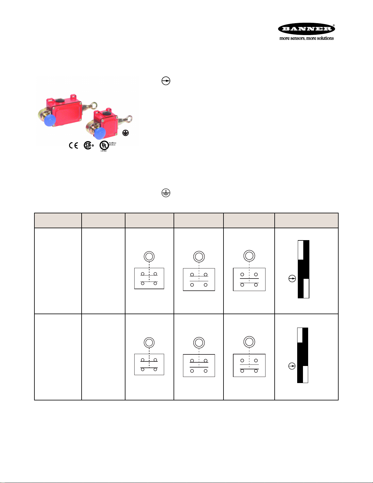
Model Max. Rope
Length
RP-QM72D-6L 6 m (20 ft)
RP-QM72D-12L 12 m (40 ft)
Run Position Cable Pulled Cable Break Switching Diagram
.
P/N 62084 Rev. C 27 January 2014
Page 2
25 26
13 14
25 26
13 14
25 26
13 14
13-14
25-26
Break
Pull
50N
180N
0 (0)
2 (0.08)
11 (0.43)
13 (0.51)
mm (in)
25 26
45 46
13 14
33 34
25 26
45 46
13 14
33 34
25 26
45 46
13 14
33 34
26
14
13-14
25-26
Break
Pull
80N
200N
0 (0)
2 (0.08)
6 (0.24)
8 (0.32)
mm (in)
33-34
45-46
Break
Pull
25 26
13 14
33 34
25 26
13 14
33 34
25 26
13 14
33 34
13-14
25-26
Break
Pull
80N
200N
0 (0)
2 (0.08)
6 (0.24)
8 (0.32)
mm (in)
33-34
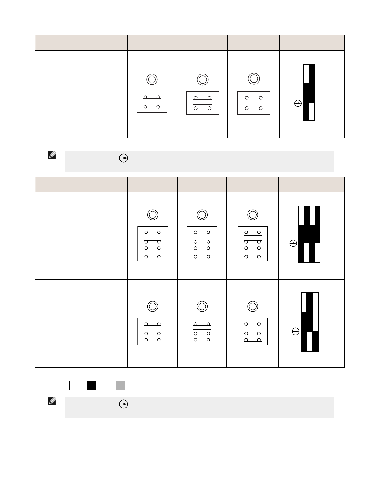
AUX
Rope Pull Switches
Model Max. Rope
Length
RP-QMT72D-20L 20 m (65 ft)
NOTE: This symbol
diagram to identify the point in actuator travel where the normally-closed safety contact is fully open.
Model Max. Rope
Length
Run Position Cable Pulled Cable Break Switching Diagram
for a positive-opening safety contact (IEC 60947-5-1) is used in the switching
Run Position Cable Pulled Cable Break Switching Diagram
RP-QMT72F-12L 12 m (40 ft)
RP-QMT72E-12L 12 m (40 ft)
Contacts: Open Closed Transition
NOTE:
diagram to identify the point in actuator travel where the normally-closed safety contact is fully open.
This symbol for a positive-opening safety contact (IEC 60947-5-1) is used in the switching
2 www.bannerengineering.com - tel: 763-544-3164 P/N 62084 Rev. C
Page 3

Rope Pull Switches
Important... Read This First
Regarding the Use of Rope Pull Switches. In the United States, the functions that Banner rope pull switches are
intended to perform are regulated by the Occupational Safety and Health Administration (OSHA). Whether or not any
particular rope pull switch installation meets all applicable OSHA requirements depends upon factors that are beyond the
control of Banner Engineering Corp. These factors include the details of how the switches are applied, installed, wired,
operated, and maintained.
Banner Engineering Corp. has attempted to provide complete application, installation, operation, and maintenance
instructions in this document. Direct any questions regarding the use or installation of rope pull switches to the factory
applications department.
Banner Engineering Corp. recommends that rope pull switches be applied according to the guidelines set forth in the
standards listed below. In addition, the user is responsible for ensuring all local, state, and national laws, rules, codes, and
regulations relating to the use of Banner rope pull switches in each application are satisfied. Extreme care is urged that all
legal requirements are met and that all installation and maintenance instructions are followed.
Applicable U.S. Standards
OSHA Code of Federal Regulations: Title 29, Parts 1900 to 1910
Available from: Superintendent of Documents, Government Printing Office, P.O. Box 371954, Pittsburgh, PA 15250-7954,
Tel: 202-512-1800
ANSI B11 Standards for Machine Tools Safety
Contact: Safety Director, AMT – The Association for Manufacturing Technology, 7901 Westpark Drive, McLean, VA 22102,
Tel.: 703-893-2900
Applicable European and International Standards
ISO/TR 12100-1 (EN 292-1 & -2) Safety of Machinery – Basic Concepts, General Principles for Design
ISO 13852 (EN 294) Safety of Machinery—Safety Distances to Prevent Danger Zones Being Reached by the Upper Limbs
ISO 13853 (EN 811) Safety of Machinery—Safety Distances to Prevent Danger Zones Being Reached by the Lower Limbs
ISO 13849-1 (EN 954-1) Safety-Related Parts of Control Systems
ISO 13855 (EN 999) The Positioning of Protective Equipment in Respect to Approach Speeds of Parts of the Human Body
ISO 14119 (EN 1088) Interlocking Devices Associated with Guards – Principles for Design and Selection
IEC 60204-1 Electrical Equipment of Machines Part 1: General Requirements
IEC 60947-5-1 Low Voltage Switchgear – Electromechanical Control Circuit Devices
Contact: Global Engineering Documents, 15 Inverness Way East, Englewood, CO 80112-5704, Tel.: 800-854- 7179
Overview
Models RP-QM..72-..L are rope pull switches in heavy-duty metal housings. When used with steel wire rope, they can
provide stop actuation along conveyors and similar machinery. Red PVC-covered 3 mm diameter wire rope is
recommended (see Accessories).
Some models have redundant terminal pairs (see model listing). In such models, terminals 33/34 will follow the action of
terminals 13/14 and terminals 45/46 will follow the action of terminals 25/26. Either or both contacts 33/34 and/or 45/46
may be used as monitoring contacts. Contact pairs 33/34 also may be jumpered to pairs 45/46 (in the same way that
13/14 is jumpered to 25/26) to provide dual-channel input to a safety device. When the rope is properly tensioned (using
a turnbuckle), both contacts of the switch are closed. A groove on the actuator aligns with the end of the housing flange
when tension is set for operation. When the rope is pulled, the positive-break contact between terminals 25 and 26 (and
terminals 45 and 46, for model RP-QMT72E-12L) latches open. If the rope breaks or goes slack, the contact between
terminals 13 and 14 (and terminals 33 and 34, for models RP-QMT72E-12L and RP-QMT72F-12L) opens. These contacts
typically should be wired together, in series.
P/N 62084 Rev. C www.bannerengineering.com - tel: 763-544-3164 3
Page 4

Reset Button
Pull to Reset
Rope Tension
Indicator
Cover Plate
Screws (4)
Rope Pull Switches
These rope pull switches are not safeguarding devices, in that they
do not protect personnel from injury. They provide the same
function as other types of stop switches.
All five models feature “latching” operation. When the rope is pulled,
the switch contacts 25/26 (and 45/46, depending on model) open
and remain open until the built-in reset button is manually pulled to
reset.
Figure 1. Features
WARNING: Not a Safeguarding Device
An Emergency Stop Device is not considered a safeguarding device because it requires an
overt action by an individual to stop machine motion or hazards.
A safeguarding device limits or eliminates an individual's exposure to a hazard without action by the
individual or others. Because an individual must actuate the device for it to function, these devices do
not fit the definition of a safeguarding device and cannot be substituted for required safeguarding. Refer
to the relevant standards to determine those requirements.
Mechanical Installation
Installation Guidelines
• The rope should be easily accessible and visible along its entire length. Markers or flags may be fixed on the rope
to increase its visibility
• Mounting points, including support points, must be rigid and allow sufficient space around the rope to allow easy
access
• The rope should be free of friction at all supports. Pulleys are recommended
• Use only pulleys (not eye bolts) when routing the rope around a corner or whenever direction changes, even
slightly
• Never run rope through conduit or other tubing
• Never attach weights to the rope
• Temperature affects rope tension. The rope expands (lengthens) when temperature increases, and contracts
(shrinks) when temperature decreases. Significant temperature variations require frequent checks of the tension
adjustment
• Do not exceed the maximum specified total rope length. Banner offers models for other spans; contact Banner
Engineering or visit www.bannerengineering.com for model selection
4 www.bannerengineering.com - tel: 763-544-3164 P/N 62084 Rev. C
Page 5

150 mm
(6") max.
L1
L2
25 mm
(1") min.
400 mm (16") max.
for Actuation of Switch
NOTE:
Force to actuate must
not exceed 200 N (45 lbf)
Wire in Series
Tension Indicator Mark
Rope Pull Switches
Figure 2. Assembly of Rope and Hardware
Model
RP-QM72D-6L 6 m (20 ft) 3 m (10 ft)
RP-QM72D-12L 12 m (40 ft) 4 m (13 ft)
RP-QMT72D-20L 20 m (66 ft) 5 m (17 ft)
RP-QMT72E-12L 12 m (40 ft) 4 m (13 ft)
RP-QMT72F-12L 12 m (40 ft) 4 m (13 ft)
Max. Total Length L1 Max. Distance Between Pulleys L2
Installation Procedure
1. Mount the switch securely on a solid, stationary surface.
2. Fasten an eye bolt at the opposite end of the rope span, up to 6 m (20 ft), or 12 m (40 ft) or 20 m (66 ft) from the
switch, depending on model. The anchor for the eye bolt also must be solid and stationary, to withstand the
constant tension of the rope.
3. Assemble the rope, as shown. Keep the rope’s PVC cover intact along its complete length.
4. Use pulleys (recommended) or eye bolts at each support point. A pulley must be used when routing the rope
around a corner, regardless of the angle.
5. Apply tension to the rope using the turnbuckle until the indicator mark on the switch aligns with the leading edge of
the housing flange. This indicates sufficient rope tension. (Contacts 25/26, and 45/46, if applicable, will close.)
6. Pull hard on the rope and reset the latch several times. If contact 25/26 (45/46) remains open following the reset,
further tighten the turnbuckle, until contact 25/26 (45/46) closes.
7. Repeat step 6 until contact 25/26 (45/46) remains closed for the Run condition.
All hardware is supplied by the user. The switch mounting holes are on a mounting pattern of 72 x 40 or 72 x 76
millimeters, and accept M5 (#10) hardware. Wire rope and associated hardware may be ordered separately; see
Accessories.
Figure 3. Run Position: Proper Rope Tension
Figure 4. Rope Pulled: Contact 25/26 (45/46) Opens
P/N 62084 Rev. C www.bannerengineering.com - tel: 763-544-3164 5
Page 6

132514
26
Install
Jumper Wire
Between
Contacts
To
Machine
Control
Stop
Circuit
Rope Pull Switches
Figure 5. Rope Break or Slack: Contact 13/14 (33/34) Opens
Electrical Installation
Access to the Wiring Chamber. The wiring chamber is
accessed via a cover plate (remove four screws). A conduit
adapter is supplied to convert the 20 millimeter threaded
entrance to 1/2-inch NPT. An accessory cable gland that fits the
M20 thread is also available (see Accessories).
Wiring. Install a jumper wire to place switch contacts 13/14
and 25/26 in series, as shown.
For model RP-QMT72F-12L, install a jumper wire to place
contacts 33/34 and 45/46 in series, to provide a dual-channel
output to a safety device. If dual-channel output is not required,
either or both contacts may instead be used as monitoring
outputs (in which case no jumper is required).
Figure 6. Wire the two switch contacts in series
Maintenance/Checkout
At switch installation or replacement and at machine set up, a Designated Person
machine shutdown response and check the switch(es) and installation for proper operation, physical damage, mounting
(looseness), and excessive environmental contamination. This must also take place on a periodic schedule determined by
the user, based on the severity of the operating environment and the frequency of switch actuations. Adjust, repair, or
replace components as needed. If inspection reveals contamination on the switch, thoroughly clean the switch and
eliminate the cause of the contamination. Replace the switch and/or appropriate components when any parts or
assemblies are damaged, broken, deformed, or badly worn; or if the electrical/mechanical specifications (for the
environment and operating conditions) have been exceeded. Always test the control system for proper functioning under
machine control conditions after performing maintenance, replacing the switch, or replacing any component of the switch.
Additional items that should be included in the checkout and/or regularly scheduled maintenance of a rope pull system:
• Check for proper rope tension and adjust as needed
• Verify free operation (no binding) of the rope and proper tripping when the rope is pulled
• Periodically lubricate the pulleys and other moving parts associated with the rope
• Repair any loose or damaged hardware, worn/frayed rope (cable), missing red rope sheathing or flags/markers (if
used)
• Remove or clean off any contamination and eliminate its cause
Repairs
Contact Banner Engineering for troubleshooting of this device. Do not attempt any repairs to this Banner device; it
contains no field-replaceable components. If the device or a device component is determined to be defective by a
Banner Applications Engineer, they will advise you of Banner's RMA (Return Merchandise Authorization) procedure.
1
A Designated Person is identified in writing by the employer as being appropriately trained to perform a specified checkout procedure.
1
must test each switch for proper
6 www.bannerengineering.com - tel: 763-544-3164 P/N 62084 Rev. C
Page 7

Rope Pull Switches
Important: If instructed to return the device, pack it with care. Damage that occurs in return shipping
is not covered by warranty.
Specifications
Contact Rating
10 A at 24 V ac
10 A at 110 V ac
6 A at 230 V ac
6 A at 24V dc
2.5 kV max. transient tolerance
NEMA A300 P300
European Rating
Utilization categories: AC15 and DC13
Ui = 500 V ac; Ith = 10 A
40-60 Hz
Ue (V) Ie/AC-15 (A) Ie/DC-13 (A)
24 10 6
110 10 1
230 6 0.4
Contact Material
Silver-nickel allow
Maximum Switching Speed
50 operations per minute
Recommended Rope Size
3 mm diameter steel rope
Maximum Rope Pull Length
RP-QM72D-6L: 6 m (20 ft)
RP-QM72D-12L: 12 m (40 ft)
RP-QMT72D-20L: 20 m (66 ft)
RP-QMT72E-12L: 12 m (40 ft)
RP-QMT72F-12L: 12 m (40 ft)
Short Circuit Protection
10 amp Slow Blow, 15 amp Fast Blow. Recommended
external fusing or overload protection.
Mechanical Life
1 million operations
Wire Connections
Screw terminals with pressure plates accept the
following wire sizes –
Stranded and solid: 20 AWG (0.5 mm2) to 16 AWG
(1.5 mm2) for one wire
Stranded: 20 AWG (0.5 mm2) to 18 AWG (1.0 mm2)
for two wires
Cable Entry
M20 x 1.5 threaded entrance. Adapter supplied to
convert M20 x 1.5 to ½"-14 NPST threaded entrance
Construction
Aluminum alloy die-cast
Environmental Rating
IEC IP65
Operating Conditions
Temperature: –30 to 80 °C (–22 to 176 °F)
Weight
RP-QM72D-6L: 0.49 Kg (1.08 lbs)
RP-QM72D-12L: 0.52 Kg (1.15 lbs)
RP-QMT72D-20L: 0.64 Kg (1.41 lbs)
RP-QMT72E-12L: 0.64 Kg (1.41 lbs)
RP-QMT72F-12L: 0.64 Kg (1.41 lbs)
Certifications
P/N 62084 Rev. C www.bannerengineering.com - tel: 763-544-3164 7
Page 8

M20
82.0 mm
(3.23")
72.0 mm
(2.83")
56.0 mm
(2.21")
33.0 mm
(1.30")
53.0 mm
(2.09")
Ø 15.0 mm (0.59")
7.0 mm
(0.28")
40.0 mm
(1.58")
5.0 mm
(0.20")
4x 5.4 mm
(0.21")
20.5 mm
(0.81")
5.0 mm (0.20")
44.0 mm
(1.73")
8.5 mm
(0.33")
69.0 mm
(2.72")
M20 x 1.5 M20 x 1.5
Pg13.5
82.0 mm
(3.23")
72.0 mm
(2.83")
95.5 mm
(3.76")
33.0 mm
(1.30")
53.0 mm
(2.09")
Ø 15.0 mm (0.59")
Ø 25.0 mm (0.98")
12 mm
(0.47")
76 mm
(2.99")
7.5 mm
(0.30")
4x 5.4 mm
(0.21")
20.5 mm
(0.81")
5.0 mm (0.20")
45.5 mm
(1.79")
8.5 mm
(0.33")
69.0 mm
(2.71")
M20 x 1.5
M20 x 1.5
Rope Pull Switches
Dimensions
Figure 7. RP-QM72D-6L and RP-QM72D-12L
8 www.bannerengineering.com - tel: 763-544-3164 P/N 62084 Rev. C
Figure 8. RP-QMT72D-20L, RP-QMT72E-12L, and RP-QMT72F-12L
Page 9

M20 x 1.5
24.0 mm
(0.94")
35.5 mm
(1.40")
23.0 mm
(0.91")
M20 x 1.5
24.0 mm
(0.94")
1/2"-14 NPT
Internal Thread
O-ring
Thimble Clamp
Pulley
Turnbuckle Eye Bolt
Rope Pull Switches
Accessories
Cable Glands
Model Size
For Cable
Diameter
5.0 to 12.0 mm
SI-QM-CGM20 M20 × 1.5 Metal
(0.20 to 0.47
inches)
Conduit Adapters
Model
SI-QM-M20
Size Thread Conversion Dimensions Used With
½ in-14 NPT
Metal
M20 × 1.5 to ½
in-14 NPT
One conduit adapter is supplied with each switch.
Dimensions Used With
SI-LM40 Safety Interlock
Switches
SI-QM100 Safety Interlock
Switches
RP-RM83 Rope Pull Switches
RP-LM40 Rope Pull Switches
RP-QM72/QMT72 Rope Pull
Switches
RP-QM90 Rope Pull Switches
SI-LM40 Safety Interlock
Switches
SI-QM100 Safety Interlock
Switches
RP-RM83 Rope Pull Switches
RP-LM40 Rope Pull Switches
RP-QM72/QMT72 Rope Pull
Switches
RP-QM90 Rope Pull Switches
Components for the Wire Rope Assembly
Model
RPA-C2-10 10 m (33 ft)
RPA-C2-20 20 m (66 ft)
RPA-C2-50 50 m (264 ft)
RPA-C2-80 80 m (264 ft)
Model Quantity Description Thimble
RPA-T2-4 4 Thimble for 3 mm wire rope
Length Description Wire Rope
3 mm steel wire rope with 0.5 mm red PVC jacket
(unterminated)
P/N 62084 Rev. C www.bannerengineering.com - tel: 763-544-3164 9
Page 10

Model Quantity Description Clamp
RPA-CC2-4 4 Clamp for 3 mm wire rope
Model Quantity Description Turnbuckle
RPA-TA1-1 1 #4 Turnbuckle
Model Quantity Description Eye Bolt
RPA-EB1-1 1 ¼"-20 Eye bolt (3" bolt shaft)
Model Quantity Description Pulley
RPA-P1-1 1 Hanging pulley for in-line use
Rope Pull Switches
Banner Engineering Corp Limited Warranty
Banner Engineering Corp. warrants its products to be free from defects in material and workmanship for one year following
the date of shipment. Banner Engineering Corp. will repair or replace, free of charge, any product of its manufacture
which, at the time it is returned to the factory, is found to have been defective during the warranty period. This warranty
does not cover damage or liability for misuse, abuse, or the improper application or installation of the Banner product.
THIS LIMITED WARRANTY IS EXCLUSIVE AND IN LIEU OF ALL OTHER WARRANTIES WHETHER EXPRESS OR
IMPLIED (INCLUDING, WITHOUT LIMITATION, ANY WARRANTY OF MERCHANTABILITY OR FITNESS FOR A
PARTICULAR PURPOSE), AND WHETHER ARISING UNDER COURSE OF PERFORMANCE, COURSE OF DEALING OR
TRADE USAGE.
This Warranty is exclusive and limited to repair or, at the discretion of Banner Engineering Corp., replacement. IN NO
EVENT SHALL BANNER ENGINEERING CORP. BE LIABLE TO BUYER OR ANY OTHER PERSON OR ENTITY FOR
ANY EXTRA COSTS, EXPENSES, LOSSES, LOSS OF PROFITS, OR ANY INCIDENTAL, CONSEQUENTIAL OR
SPECIAL DAMAGES RESULTING FROM ANY PRODUCT DEFECT OR FROM THE USE OR INABILITY TO USE THE
PRODUCT, WHETHER ARISING IN CONTRACT OR WARRANTY, STATUTE, TORT, STRICT LIABILITY,
NEGLIGENCE, OR OTHERWISE.
Banner Engineering Corp. reserves the right to change, modify or improve the design of the product without assuming any
obligations or liabilities relating to any product previously manufactured by Banner Engineering Corp.
www.bannerengineering.com - tel: 763-544-3164
 Loading...