

Page 1
QM42 Series
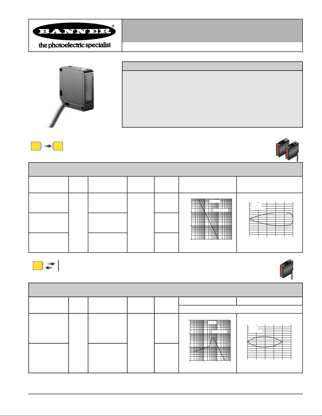
Self-contained dc photoelectric sensors in metal housings
Printed in USA P/N 44487
• Compact, rugged, low cost self-contained sensors in metal die cast housings
• Epoxy-encapsulated circuitry; leakproof IP67 (NEMA 6) construction for
harsh sensing environments
• Outstanding electrical noise immunity
• Dual LED system indicates sensor performance
• Choice of integral cable or quick disconnect connector
Features
QM42 Opposed Mode Emitter (E) and Receiver (R)
Models Range Cable
Supply
Voltage
Output
Type Excess Gain
Beam Pattern
Effective Beam: 8 mm
QM426E
QM426EQ
10 m
(33 ft)
2 m (6.5 ft)
4-pin Euro QD
10-30V dc
—
QM42VN6R
QM42VN6RQ
2 m (6.5 ft)
4-pin Euro QD
NPN
QM42VP6R
QM42VP6RQ
2 m (6.5 ft)
4-pin Euro QD
PNP
QM42 Diffuse Mode
QM42VN6D
QM42VN6DQ
400 mm
(16 in)
2 m (6.5 ft)
4-pin Euro QD
10-30V dc
NPN
Models Range Cable
Supply
Voltage
Output
Type
Excess Gain Beam Pattern
QM42VP6D
QM42VP6DQ
2 m (6.5 ft)
4-pin Euro QD
PNP
1
10
100
1 m
3.3 ft
10 m
33 ft
100 m
330 ft
.1 m
.33 ft
1000
E
X
C
E
S
S
G
A
I
N
DISTANCE
QM42E/R
Opposed Mode
10 m
32.5 ft
8 m
26 ft
6 m
19.5 ft
4 m
13 ft
2 m
6.5 ft
0
0
100 mm
200 mm
300 mm
100 mm
200 mm
300 mm
0
4 in
8 in
12 in
4 in
8 in
12 in
DISTANCE
QM42E/R
Opposed Mode
Performance based on 90% reflectance white test card
Infrared, 880 nm
Infrared, 880 nm
1000
E
X
C
100
E
S
S
10
G
A
I
N
1
1 mm
.04 in
10 mm
.4 in
DISTANCE
QM42D
Diffuse Mode
100 mm
4 in
1000 mm
40 in
30 mm
20 mm
10 mm
10 mm
20 mm
30 mm
0
0
QM42D
Diffuse Mode
100 mm
4 in
200 mm
8 in
DISTANCE
300 mm
12 in
400 mm
16 in
500 mm
20 in
1.2 in
0.8 in
0.4 in
0
0.2 in
0.4 in
0.6 in
Page 2
QM42 Series
page 2 Banner Engineering Corporation
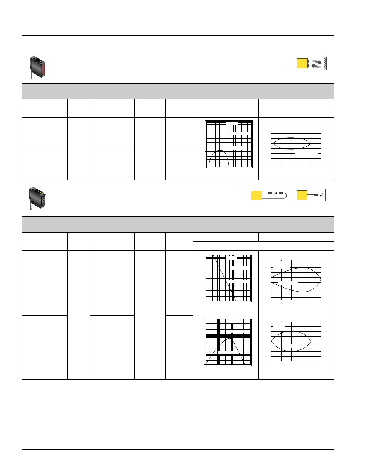
QM42 Polarized Retroreflective Mode
Models Range Cable
Supply
Voltage
Output
Type Excess Gain Beam Pattern
QM42VN6LP
QM42VN6LPQ
3 m
(10 ft)
2 m (6.5 ft)
4-pin Euro QD
10-30V dc
NPN
QM42VP6LP
QM42VP6LPQ
2 m (6.5 ft)
4-pin Euro QD
PNP
QM42 Plastic Fiber Optic Mode
Models Range Cable
Supply
Voltage
Output
Type
Excess Gain Beam Pattern
QM42VN6FP
QM42VN6FPQ
40 mm
(1.5 in)
2 m (6.5 ft)
4-pin Euro QD
10-30V dc
NPN
QM42VP6FP
QM42VP6FPQ
2 m (6.5 ft)
4-pin Euro QD
PNP
Diffuse Mode Performance Based on 90% Reflectance White Test Card
Notes:
1) 9 m (30 ft) cables are available by adding suffix "W/30" to the model number of any cabled sensor (e.g. QM42VN6D W/30).
2) A model with a QD connector requires an optional mating cable.
P
Visible red, 660 nm
Visible red, 660 nm
1000
E
X
C
100
E
S
S
10
G
A
I
N
1
.1 m
.33 ft
QM42LP
with BRT-3 Reflector
1 m
3.3 ft
DISTANCE
1000
E
X
C
100
E
S
S
10
G
A
I
N
1
1 mm
0.04 in
1000
E
X
C
100
E
S
S
10
G
A
I
N
1
0.1 mm
0.004 in
QM42FP
10 mm
0.4 in
DISTANCE
QM42FP
with PBT46U Fiber
1 mm
0.04 in
DISTANCE
Retroreflective Mode
10 m
33 ft
Opposed Mode
with PIT46U Fibers
100 mm
4.0 in
Diffuse Mode
10 mm
0.4 in
QM42LP
60 mm 2.4 in
Retroreflective Mode
40 mm 1.6 in
20 mm
0
20 mm
40 mm
60 mm
1.5 m
0.75 m
0
5.0 ft
100 m
330 ft
2.5 ft
DISTANCE
QM42FP
30 mm
Opposed Mode
20 mm
10 mm
0
with PIT46U Fibers
10 mm
20 mm
30 mm
40 mm
20 mm
6 mm
4 mm
2 mm
2 mm
4 mm
6 mm
0
0
QM42FP
Diffuse Mode
0
0.8 in
with PBT46U Fiber
10 mm
0.4 in
1.6 in
DISTANCE
20 mm
0.8 in
DISTANCE
1000 mm
40 in
100 mm
4.0 in
with BRT-3 Reflector
3.0 m
2.25 m
10.0 ft
7.5 ft
80 mm
60 mm
3.2 in
2.4 in
40 mm
30 mm
1.6 in
1.2 in
3.75 m
12.5 ft
100 mm
4.0 in
50 mm
2.0 in
0.8 in
0
0.8 in
1.6 in
2.4 in
1.2 in
0.8 in
0.4 in
0
0.4 in
0.8 in
1.2 in
0.24 in
0.16 in
0.08 in
0
0.08 in
0.16 in
0.24 in
Page 3

QM42 Series
Banner Engineering Corporation page 3
DC Product Specifications
Sensing Beam
Adjustments All models except emitters: 15-turn slotted brass GAIN (sensitivity) adjustment potentiometer
(clutched at both ends of travel)
Supply Protection Circuitry Protected against reverse polarity and transient voltages
Output Configuration SPDT (complementary) solid-state dc switch; Choose NPN (current sinking) or PNP (current sourcing) models.
Light operate:
N.O. output conducts when the sensor sees its own (or the emitter's) modulated light
Dark operate:
N.C. output conducts when the sensor sees dark
Output Rating 100 mA maximum (each output)
Off-state leakage current: <5 microamps at 30V dc;
On-state saturation voltage: <1V at 10 mA dc; <1.5V at 100 mA dc
Output Protection Circuitry Protected against false pulse on power-up and continuous overload or short-circuit of outputs
Overload trip point ≥150mA, typical, at 20ºC
Output Response Time Diffuse and retroreflective modes: 1 millisecond on and off
Opposed mode: 1 millisecond on, 0.5 millisecond off
Fiber optic mode: 0.25 millisecond on and off
Indicators Two LEDs:Green and Yellow
GREEN glowing steadily = power to sensor is "on" Opposed emitters: Green power "on"
GREEN flashing = output is overloaded
YELLOW glowing steadily = light is sensed; normally open output "on"
YELLOW flashing = marginal excess gain (1-1.5x) in light condition
Repeatability Diffuse and retroreflective modes: 250 microseconds
Opposed Mode: 120 microseconds
Fiber optic mode: 60 microseconds
Construction Housings are die-cast zinc alloy with black epoxy powder paint finish; lenses are acrylic
Environmental Rating IP67; NEMA 6
Connections 2 m (6-1/2 ft) or 9 m (30-ft) attached cable, or 4-pin euro-style quick-disconnect fitting; Cables for QD
models are purchased separately
Operating Temperature -20º to +70ºC (-7º to 158ºF); Maximum relative humidity 90% at 50ºC (non-condensing)
Infrared, 880 nm for opposed and diffuse; Visible red, 660 nm for fiber optic and retroreflective modes
Supply Voltage and Current 10 to 30V dc (10% maximum ripple) at less than:
Diffuse and retroreflective models: 20 milliamps
Opposed mode: 30 milliamps (emitter), 10 milliamps (receiver)
Fiber optic models: 30 milliamps
Page 4

QM42 Series
page 4 Banner Engineering Corporation
20.1 mm
(0.79 in)
45.5 mm
(1.79 in)
2.5 mm
(0.10 in)
90º
20º
3.05 mm Slot
(0.120 in)
ø 3.05 mm
(0.120 in)
31.8 mm
(1.25 in)
5.1 mm R
(0.20 in)
24.1 mm R
(0.95 in)
15º (2)
C
L
20.3 mm
(0.80 in)
3.1 mm R (2)
(0.12 in)
4.32 mm
Slot (2)
(0.170 in)
10º (Typ)
Dimensions
12.7 mm
(0.50 in)
23.9 mm (2)
(0.94 in)
ø 3.2 mm
(0.125 in)
(4 Holes)
27.1 mm (2)
(1.07 in)
42.0 mm
(1.65 in)
42.0 mm
(1.65 in)
Gain (Sensitivity) Adjustment (except emitters)
Green LED Power Indicator
Yellow LED
Output/Marginal Indicator
(Except emitters)
10.0 mm (0.39 in)
12.3 mm (0.48 in)
Threaded M4 x 0.7
Mounting Holes
42.0 mm
(1.65 in)
QM42FP Models All Other Models
45.9 mm
(1.81 in)
48.5 mm
(1.91 in)
12.7 mm
(0.50 in)
23.9 mm (2)
(0.94 in)
ø 3.2 mm
(0.13 in)
(4 Holes)
M12 x 1 x 18 mm
Euro-style
27.1 mm (2)
(1.07 in)
42.0 mm
(1.65 in)
42.0 mm
(1.65 in)
Gain (Sensitivity) Adjustment (except emitters)
Green LED Power Indicator
Yellow LED
Output/Marginal Indicator
(Except emitters)
60.2 mm
(2.37 in)
42.0 mm
(1.65 in)
45.9 mm
(1.81 in)
48.5 mm
(1.91 in)
QM42FP Models All Other Models
Cabled models
Quick-disconnect models
Accessory Mounting Bracket SMB19
Supplied with hardware
Page 5

QM42 Series
Banner Engineering Corporation page 5
Quick Disconnect (QD) Cables
The following is the selection of cables available for the QM42 QD models
DImensionsStyle Model Length For use with
4-pin
Euro Style
straight
MQDC-406
MQDC-415
MQDC-430
2 m (6.5 ft)
5 m (15 ft)
9 m (30 ft)
All QM42 sensors with
quick-disconnect fitting
Pinout
4-pin
Euro Style
right-angle
MQDC-406RA
MQDC-415RA
MQDC-430RA
2 m (6.5 ft)
5 m (15 ft)
9 m (30 ft)
Sensors with NPN (Sinking) Outputs Sensors with PNP (Sourcing) Outputs
Cabled Models Cabled Models
Quick Disconnect Models Quick Disconnect Models
bu
bn
-
+
bk
wh
Load
Load
Load
Load
10-30V dc
bn
bu
-
+
bk
wh
Load
Load
10-30V dc
bu
bn
-
+
bk
wh
Load
Load
10-30V dc
bn
bu
-
+
bk
wh
10-30V dc
Load
Load
bn
bu
+
-
10-30V dc
DC Emitters
Cabled Models
bn
bu
10-30V dc
-
+
bk
wh
Quick Disconnect Models
Hookup Diagrams
44 mm max.
(1.7 in)
38 mm max.
(1.5 in)
M12 x 1
ø15 mm
(0.6 in)
ø15 mm
(0.6 in)
M12 x 1
38 mm max.
(1.5 in)
Brown Wire
Black Wire
Pin #1
Pin #4
Pin #2
White Wire
Pin #3
Blue Wire
Page 6

Banner Engineering Corp., 9714 Tenth Ave. No., Minneapolis, MN 55441 Telephone: (612) 544-3164 FAX (applications) (612) 544-3573
WARRANTY: Banner Engineering Corporation warrants it products to be free from defects for one year. Banner Engineering
Corporation will repair or replace, free of charge, any product of its manufacture found to be defective at the time it is returned
to the factory during the warranty period. This warranty does not cover damage or liability for the improper application of
Banner products. This warranty is in lieu of any other warranty either expressed or implied.
QM42 Series
WARNING
These photoelectric presence sensors do NOT include the self-checking redundant circuitry
necessary to allow their use in personnel safety applications. A sensor failure or malfunction can result in either
an energized or a de-energized sensor output condition.
Never use these products as sensing devices for personnel protection. Their use as a safety device may create
an unsafe condition which could lead to serious injury or death.
Only MINI-SCREEN™, MULTI-SCREEN™, MACHINE-GUARD and PERIMETER-GUARD Systems, and other systems so
designated, are designed to meet OSHA and ANSI machine safety standards for point-of-operation guarding devices. No other
Banner sensors or controls are designed to meet these standards, and they must NOT be used as sensing devices for
personnel protection.
!
 Loading...