

Page 1
Q85 Series Polarized Retro Sensors
ac/dc sensors with e/m relay output and optional timing logic
Economical polarized retroreective sensor in rug-
•
ged, NEMA-6P (IEC IP67) Cycolac® ABS housings
Sensing range of 15 feet (4,6 meters) when used with
•
Banner model BRT-3 3" retroreective target
Operates from 24 to 240 volts ac or 12 to 240 volts
•
dc; totally self-contained
SPDT electromechanical relay output device;
•
choice of on/off output or programmable timing
logic
•
Wiring chamber with two conduit entrances for
mounting versatility
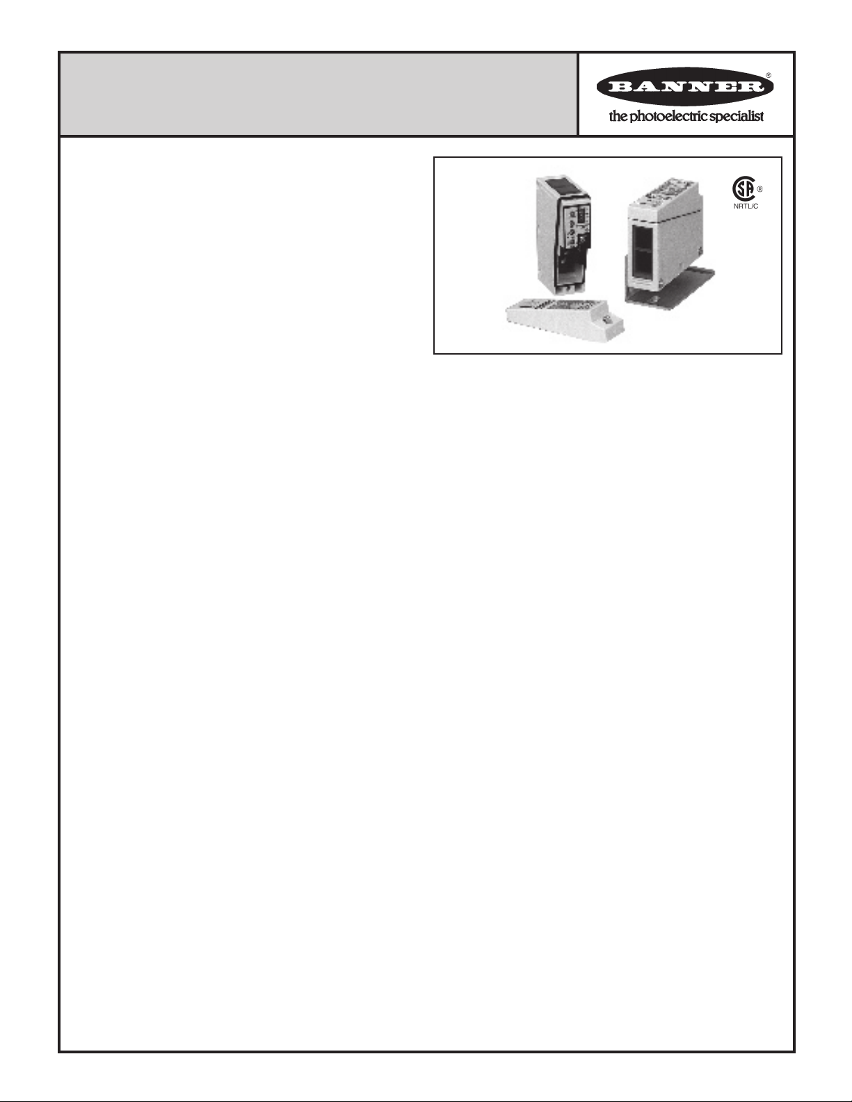
Q85VR3LP-T9
sensor with
cover removed
Mounting bracket and
hardware are included
LED indicators for OUTPUT ON and LIGHT SENSED
(AID™ signal strength indicator system, see text)
Q85s are compact, economical, polarized retroreective mode photoelectric sensors in rugged NEMA-6P rated ABS housings. They
are ideally suited to conveyor control and similar applications. The
timing logic functions offered in the "T9" models provide additional
control capabilities over and above the basic model's ON/OFF (no
delay) function. The special lens of Q85 sensors polarizes the emitted light and lters out unwanted reections, allowing use in many
applications that are otherwise unsuited to retroreective sensing.
The Q85's maximum range of 15 feet (4,6 meters) is obtained using the Banner model BRT-3 3" diameter round retroreector. All
Q85 sensors feature a convenient wiring chamber with two conduit
entrances for ease of connection, positioning, and mounting.
Q85 Series sensors operate from either 24-240V ac or 12-240V dc
and draw 2 watts maximum. They have SPDT electromechanical
relay output, and are available with a choice of either ON/OFF or
programmable timing output logic. Models with programmable
timing logic ("T9" models) provide eight switch-selectable logic
functions: ON/OFF (no delay), ON delay, OFF delay, ON/OFF
delay, one-shot (pulse), on-delayed one-shot, limit timer, and ondelayed limit timer. The adjustable time range for delay functions
and pulse length is 0.1 to 5 seconds (see page 2).
Two top-mounted LED indicators are provided. A red indicator
(Banner's exclusive, patented AID™ system*) lights whenever
the sensor "sees" the reection of its own modulated light source,
and pulses at a rate proportional to the strength of the received
light signal. A yellow output indicator lights whenever the Q85's
output is energized.
Q85 Series sensors have rugged yellow Cycolac® ABS housings
with ultrasonically-welded acrylic lenses. A gasketed ABS cover
protects the wiring chamber and the timing and sensitivity adjustment controls. Two 1/2-14 NPSM conduit entrances are provided;
a plug and gasket are included for a possible unused entrance. Q85
Series sensors are rated NEMA 1, 2, 3, 3S, 4, 4X, 6, 6P, 12, and
13 (IEC IP67). An 11-gauge plated steel mounting bracket and
two plated mounting bolts and nuts (see photo and page 2) are
included.
Cycolac® is a registered trademark of General Electric Co.
*Alignment Indicating Device system, US patent number 4356393
Specications, Q85 Series Polarized Retro Sensors
Sensing range:
3 inches (8 cm) to 15 feet (4,6 meters) when used with Banner model
BRT-3 3" reective target.
Sensing beam: visible red, 680 nanometers (polarized).
Supply voltage: 24 to 240V ac, 50/60 Hz or 12 to 240V dc (2 watts
maximum). No polarity for power supply hookup.
Models and Output Congurations:
Q85VR3LP = SPDT e/m relay, on/off output
Q85VR3LP-T9 = SPDT e/m relay, with programmable timer
Output relay specications:
Maximum switching power (resistive load): 90W, 750VA. Install
transient suppressor (MOV) across contacts that switch inductive loads.
Maximum switching voltage (resistive load): 250V ac or 30V dc.
Maximum switching current (resistive load): 3A.
Minimum voltage and current: 5V dc, 10 mA.
Mechanical life: 50,000,000 operations.
Electrical life at full resistive load: 100,000 operations.
Maximum switching speed: 25 operations per second.
Closure time (no timing logic in use): 20 milliseconds max.
Release time (no timing logic in use): 20 milliseconds max.
Repeatability (no timing logic in use): 1 millisecond.
All sensors are protected against false pulse on power-up. (False pulse
protection circuit causes a 100 millisecond delay on power-up.)
Adjustments: All models have a single-turn SENSITIVITY control
potentiometer, accessible beneath the ABS wiring chamber cover (T9
models also have a light/dark operate switch). Timing logic (T9 models
only) is congured at a DIP switch. Pulse length and delay are set by a
single-turn potentiometer (accessible under the wiring chamber cover).
The adjustable time range for both functions is 0.1 to 5 seconds; both
functions are automatically set to the same value.
Status Indicators: LEDs, one red and one yellow, both top-
mounted.
Red AID™ system (Alignment Indicating Device, US patent #4356393)
indicator LED lights whenever the sensor "sees" its own modulated light,
and pulses at a rate proportional to the strength of the light signal.
Yellow indicator lights whenever the sensor's output is energized.
Construction:
Yellow Cycolac® ABS housing, plated steel hardware. Acrylic lens.
ABS cover for wiring/adjustments access. Rated NEMA 1, 2, 3, 3S, 4,
4X, 6, 6P, 12, and 13; IEC IP67. It is the customer's responsibility to
maintain NEMA 6P integrity at the conduit entrance(s) in use. Maximum
wire size (for connection to wiring terminals) is #14 AWG.
Operating temperature range: -25° to +55°C (-13° to +131°F).
Maximum relative humidity: 90% at 50°C (non-condensing).
Printed in USA
P/N 30898L3A
Page 2
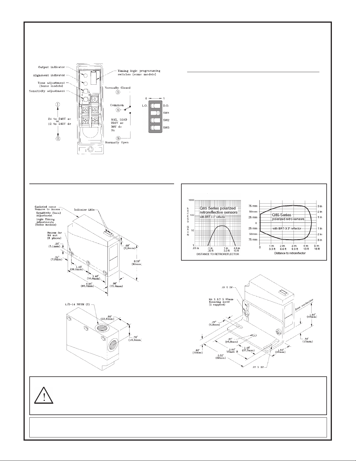
Hookup and timing logic selection
Hookup to the ac line and the external load is made at the ve terminals
inside the wiring chamber (see drawing below). There is no polarity for
power supply hookup. Output is an SPDT electromechanical relay.
Timing logic
programming
switch detail:
The output timing logic function (on sensor models with T9 model
number sufx) is selected at the timing logic programming switches,
according to the table (right). The output timing logic delays are set at
the single-turn time adjustment potentiometer. When the timing function
involves more than one time (as in ON and OFF delay, ON-delayed
one-shot, and ON-delayed limit timer functions), the potentiometer sets
both times to the same value.
Logic function Switch: SW1 SW2 SW3
ON and OFF delays (both) 0 0 0
ON delay (only) 0 0 1
OFF delay (only) 0 1 0
No delays 0 1 1
ON delayed one-shot 1 0 0
ON delayed limit timer 1 0 1
One-shot 1 1 0
Limit timer 1 1 1
With the light/dark operate switch (T9 models) set to light operate
(L.O.), the sensor's electromechanical output relay is energized when
the sensor sees the reection of its own modulated light. In the dark
operate (D.O.) position, the output is energized when the sensor does
not see the reection of its modulated light source.
Sensor sensitivity is set at the single-turn sensitivity adjustment potentiometer.
Dimensions, Q85 polarized retro sensors
Top view
Bottom view
Excess Gain Curve
Shown with mounting bracket
(included)
Beam Pattern
WARNING This photoelectric presence sensor does NOT include the self-checking redundant circuitry necessary to allow its use in personnel safety
applications. A sensor failure or malfunction can result in either an energized or a de-energized sensor output condition.
Never use this product as a sensing device for personnel protection. Its use as a safety device may create an unsafe condition which could lead to serious
injury or death. Only MACHINE-GUARD and PERIMETER-GUARD Systems, and other systems so designated, are designed to meet OSHA and ANSI
machine safety standards for point-of-operation guarding devices. No other Banner sensors or controls are designed to meet these standards, and they
must NOT be used as sensing devices for personnel protection.
WARRANTY: Banner Engineering Corporation warrants its products to be free from defects for one year. Banner Engineering Corporation will repair or replace, free of charge,
any product of its manufacture found to be defective at the time it is returned to the factory during the warranty period. This warranty does not cover damage or liability for the
improper application of Banner products. This warranty is in lieu of any other warranty either expressed or implied.
Banner Engineering Corp. 9714 10th Avenue No., Minneapolis, MN 55441 Telephone: (612) 544-3164 FAX (applications): (612) 544-3573
 Loading...