

Page 1
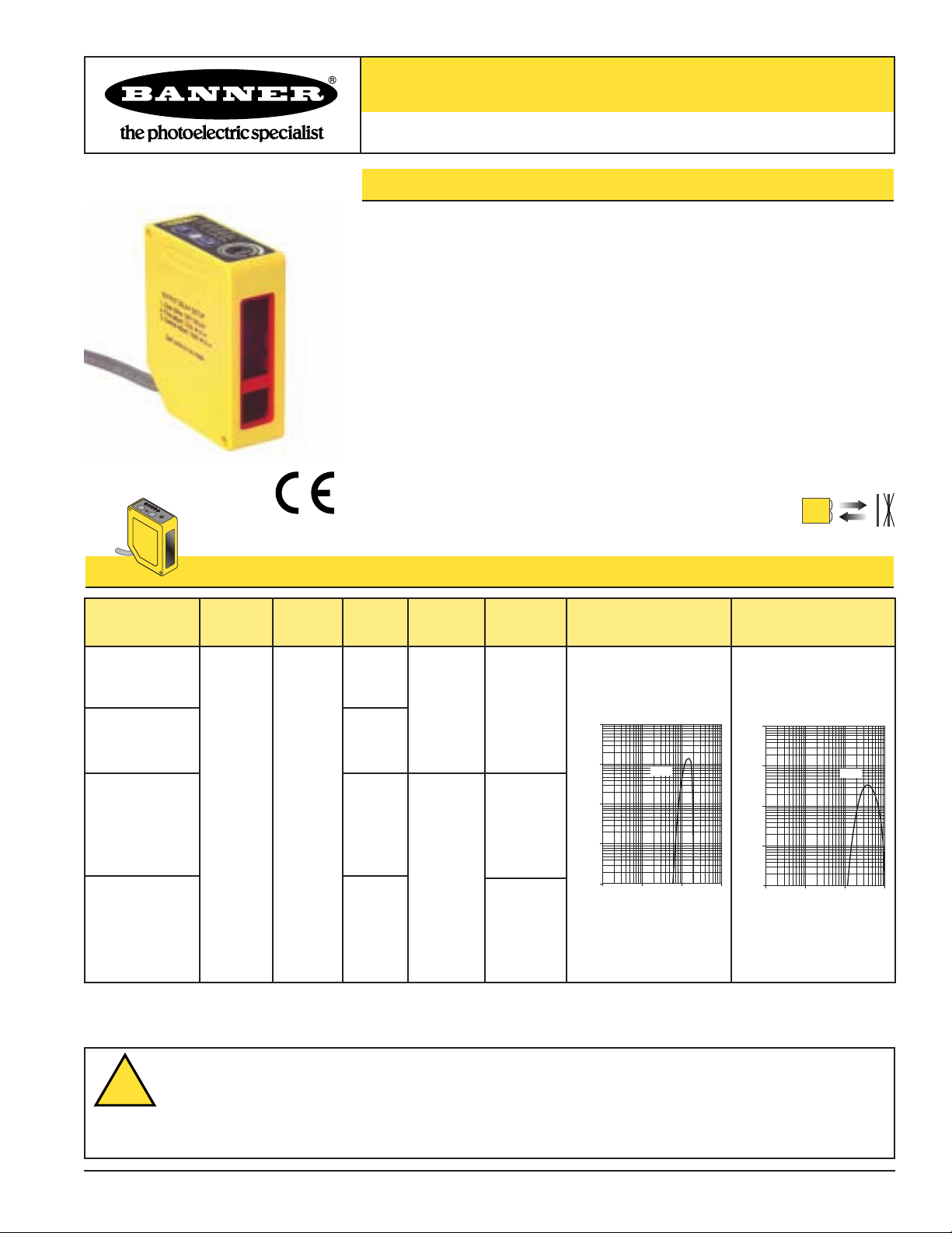
Q60AFV Series Sensors with Visible Red Emitter
Self-Contained Adjustable-Field Sensors
Q60AFV Adjustable-Field Features
• Adjustable-field background suppression sensor detects objects within a defined sensing
field, while ignoring objects located beyond the sensing field cutoff
•Two-turn, logarithmic adjustment of sensing field cutoff point from 0.2 to 1 m; allows easy
setting of cutoff point at long range
• Rotating pointer indicates relative cutoff point setting
• Easy push-button or remote programming of light/dark operate and output timing;
continuous status indicators verify all settings at a glance
• Output ON and/or OFF delays adjustable from 8 milliseconds to 16 seconds
• Powerful, highly collimated visible red sensing beam
•Tough ABS/polycarbonate blend housing is rated IEC IP67; NEMA 6
10-30V dc Models (Q60BB6AFV):
• Powered by 10 to 30V dc; bipolar (one NPN and one PNP) outputs
•Available with integral cable or rotating Euro-style quick-disconnect fitting
Universal Voltage Models (Q60VR3AFV):
• 12-250V dc or 24-250V ac, 50/60 Hz
•Available with integral cable or rotating Micro-style quick-disconnect fitting
Visible Red, 665 nm
Q60 Adjustable-Field Models
* 9 meter cables are available by adding suffix “W/30” to the model number of any cabled sensor (e.g., Q60BB6AFV1000 W/30).
A model with a QD connector requires a mating cable; see page 8.
Q60BB6AFV1000
65 mm
to 130 mm
(2.5" to 5")
depending
on cutoff
point setting
5-wire
2 m (6.5')
10-30V dc
Bipolar
NPN/PNP
Models
Minimum
Range Cable*
Supply
Voltage
Output
Type
Excess Gain at
200 mm Cutoff
Adjustable:
200 mm to
1000 mm
(8" to 40")
Cutoff
Point
m
Excess Gain at
1000 mm Cutoff
Q60BB6AFV1000Q
5-pin
Euro-style
QD
WARNING . . .
Not To Be Used for Personnel Protection
Never use these products as sensing devices for personnel protection. Doing so could lead to serious injury or death.
These sensors do NOT include the self-checking redundant circuitry necessary to allow their use in personnel safety applications. A
sensor failure or malfunction can cause either an energized or de-energized sensor output condition. Consult your current Banner Safety Products
catalog for safety products which meet OSHA, ANSI and IEC standards for personnel protection.
Q60VR3AFV1000
5-wire
2 m (6.5')
Universal
Voltage
12-250V dc
or
24-250V ac
E/M Relay
(SPDT),
normally
closed and
normally open
contacts
Q60VR3AFV1000Q1
4-pin
Micro-style
QD
E/M Relay
(SPST),
normally
open
contact
10000
1000
E
X
C
100
E
S
S
10
G
A
I
N
1
1 mm
0.04 in
Q60AFV
10 mm
100 mm
0.4 in
4 in
DISTANCE
1000
40 in
10000
1000
E
X
C
100
E
S
S
10
G
A
I
N
1
1 mm
10 mm
0.04 in
0.4 in
DISTANCE
Q60AFV
100 mm
4 in
1000 m
40 in
!
Printed in USA 02/12 P/N 69622 rev. B
Page 2
Q60V Series Adjustable-Field Sensors – Visible Red Emitter
page 2
Banner Engineering Corp. • Minneapolis, MN U.S.A.
www.bannerengineering.com • Tel: 763.544.3164
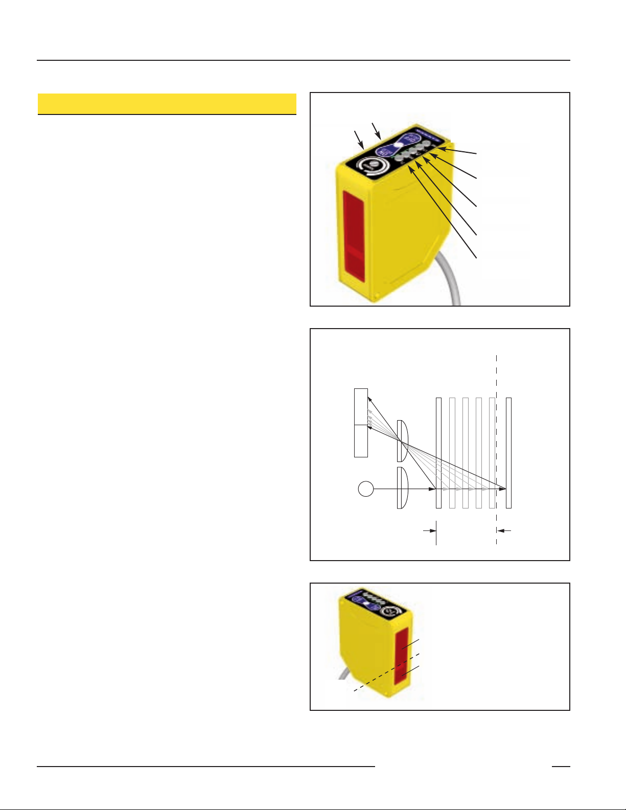
Q60AFV Overview
The Q60AFV sensor is a full-featured adjustable-field sensor.
These adjustable-field sensors are able to detect objects of
relatively low reflectivity, while ignoring other objects in the
background (beyond the cutoff point). The cutoff distance is
mechanically adjustable, using the 2-turn adjustment screw on
the sensor top (Figure 1). A rotating pointer indicates the
relative cutoff position. (The indicator moves clockwise to show
increasing distance.)
Two push buttons (ON Delay and OFF Delay) are used to set the
output delay options, to toggle between light and dark operate
modes and to lock out the push buttons for security purposes.
These functions also may be accomplished using the remote wire.
Seven LED indicators show, during RUN mode, the sensor
configuration and operating status. During Delay Configuration,
5 of the LEDs combine to form a single light bar that indicates
relative ON or OFF delay time.
Adjustable-Field Sensing — Theory of Operation
In operation, the Q60AFV compares the reflections of its
emitted light beam (E) from an object back to the sensor’s two
differently-aimed detectors R1 and R2 (see Figure 2). If the
near detector (R1) light signal is stronger than the far detector
(R2) light signal (see object A, closer than the cutoff distance),
the sensor responds to the object. If the far detector (R2) light
signal is stronger than the near detector (R1) light signal (see
object B, object beyond the cutoff distance), the sensor ignores
the object.
The cutoff distance for Q60AFV sensors is adjustable from 200
to 1000 millimeters (8" to 40"). Objects lying beyond the cutoff
distance are ignored, even if they are highly reflective. However,
it is possible to falsely detect a background object, under
certain conditions (see Background Reflectivity and Placement,
page 3).
In the drawings and discussion on this page and page 3, the
letters E, R1, and R2 identify how the sensor’s three optical
elements (Emitter “E”, Near Detector “R1”, and Far Detector
“R2”) line up across the face of the sensor. The location of
these elements defines the sensing axis (see Figure 3). The
sensing axis becomes important in certain situations, such as
those illustrated in Figures 8 and 9.
Figure 1. Q60V features
Figure 3. Q60V sensing axis
Light Sensed
Indicator
ON/OFF Delay
Push Buttons
and Indicators
Cutoff
Adjustment
Screw
Light Operate
Selected
Dark Operate
Selected
Output Conducting
(Bi-color Amber/Green)
Push Button
Lockout Indicator
Indicators Below Also
Function as a
5-Segment Light Bar During
Delay Selection Modes
Figure 2. Adjustable field sensing concept
Receiver
Elements
Near
Far
R1
R2
Lenses
Detector
Detector
Object
A
Cutoff
Distance
Object B
or
Background
E
Sensing
Range
Receiver
Elements
Emitter
Sensing
Axis
When an object approaches
from the side, the most
reliable sensing usually
occurs when the line of
approach is parallel to the
sensing axis.
Page 3
page
3
Q60V Series Adjustable-Field Sensors – Visible Red Emitter
Banner Engineering Corp. • Minneapolis, MN U.S.A.
www.bannerengineering.com • Tel: 763.544.3164
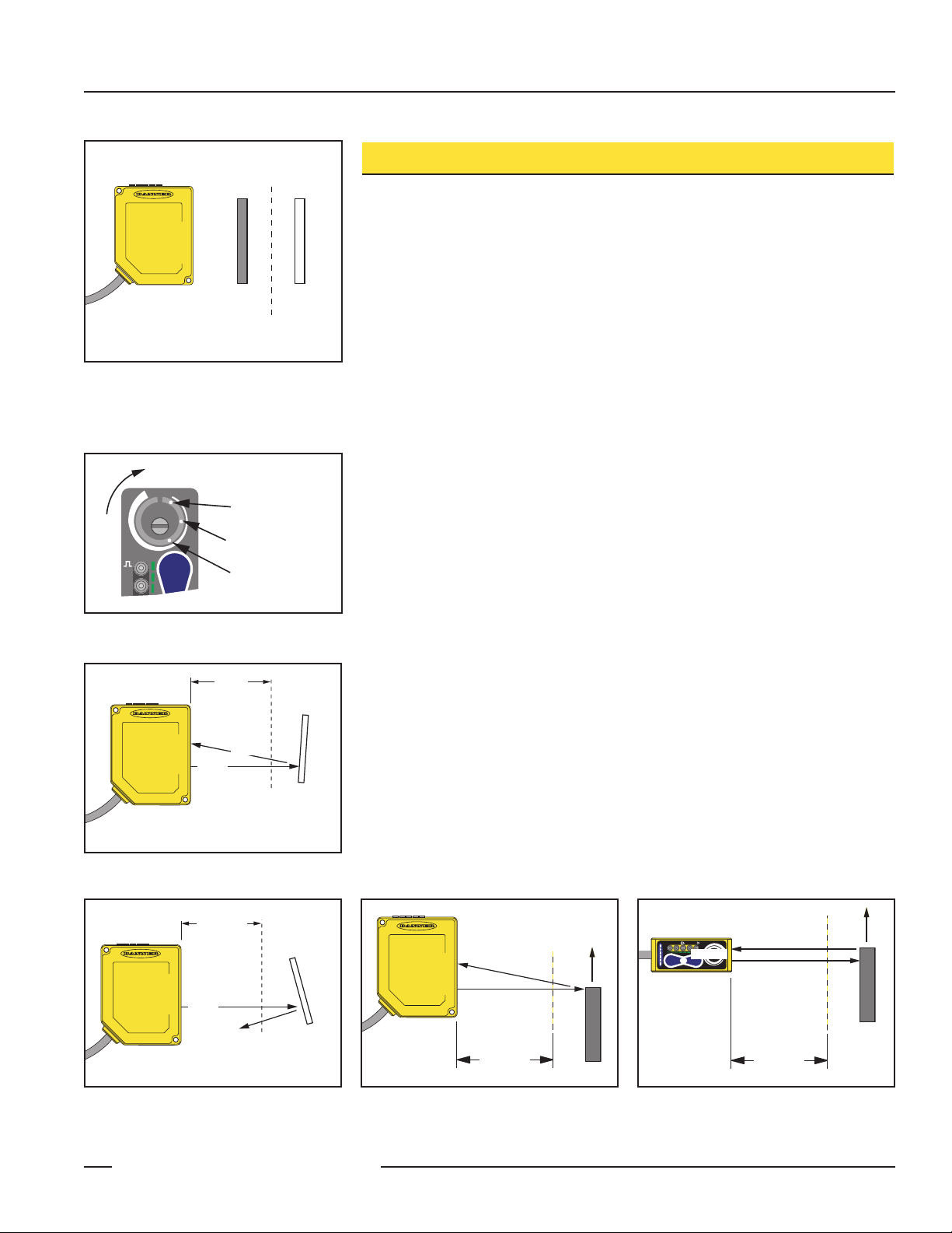
Sensor Setup
Setting the Cutoff Distance
The cutoff distance for Q60AFV sensors may be adjusted between 200 mm and
1000 mm (8" to 40").
To maximize contrast, position the lightest possible background to be used, at the
closest position it will come to the sensor during use (Figure 4). Using a small
screwdriver in the adjustment screw, adjust the cutoff distance until the threshold is
reached and the green Light Sensed indicator changes state. (If the indicator never
comes ON, the background is beyond the maximum sensing cutoff and will be
ignored.) Note the position of the rotating cutoff position indicator at this position.
Then repeat the procedure, using the darkest target, placed in its most distant
position for sensing. Adjust the cutoff so that the indicator is midway between the two
positions (Figure 5).
NOTE: Setting the cutoff distance adjustment screw to its maximum clockwise
position places the receiver lens directly in front of the receiver elements and
results in the Q60 performing as a long-range diffuse sensor.
Sensing Reliability
For highest sensitivity, the sensor-to-object distance should be such that the object
will be sensed at or near the point of maximum excess gain. The excess gain curves
on page 1 show excess gain vs. sensing distance for 200 mm and 1 m cutoffs.
Maximum excess gain for a 200 mm cutoff occurs at a lens-to-object distance of
about 150 mm, and for a 1 m cutoff, at about 400 mm. The background must be
placed beyond the cutoff distance. Following these two guidelines makes it possible
to detect objects of low reflectivity, even against close-in reflective backgrounds.
Background Reflectivity and Placement
Avoid mirror-like backgrounds that produce specular reflections. False sensor response will occur if a background surface reflects the sensor’s light more strongly to
the near detector (R1) than to the far detector (R2). The result is a false ON condition
(Figure 6). Use of a diffusely-reflective (matte) background will cure this problem.
Other possible solutions are to angle either the sensor or the background (in any
plane) so that the background does not reflect back to the sensor (see Figure 7).
An object beyond the cutoff distance, either moving or stationary (and when positioned as shown in Figure 8), can cause unwanted triggering of the sensor because it
reflects more light to the near detector than to the far detector. The problem is easily
remedied by rotating the sensor 90° (Figure 9) to align the sensing axis horizontally.
The object then reflects the R1 and R2 fields equally, resulting in no false triggering.
Figure 6. Reflective background – problem
Figure 7. Reflective background – solution
Figure 4. Set cutoff distance approximately
midway between the farthest
target and the closest background
Figure 5. Setting the cutoff distance
Figure 8. Object beyond cutoff distance —
problem
Figure 9. Object beyond cutoff distance —
solution
Target Background
R1
R2
E
Cutoff
Distance
e
r
c
n
I
e
c
n
a
t
s
i
D
g
n
i
s
a
RANGE
ON
DELAY
DO
Farthest Target Object
Set Cutoff Midway
Between
Closest Background
Sensing
Field
R1
R2
Core of
E
Emitted
Beam
E = Emitter
R1 = Near Detector
R2 = Far Detector
Strong
Direct
Reflection
to R1
Cutoff
Distance
Reflective
Background
Sensing
Field
R1
R2
Core of
E
Emitted
Beam
E = Emitter
R1 = Near Detector
R2 = Far Detector
Cutoff
Distance
Reflective
Background
Strong
Direct
Reflection
Away From
Sensor
Cutoff
Distance
R1
R2
E
Sensing
Field
SIG
DO
LO
RANGE
OFF
DELAY
DELAY
E, R1, R2
ON
Sensing
Field
Page 4

Q60V Series Adjustable-Field Sensors – Visible Red Emitter
page 4
Banner Engineering Corp. • Minneapolis, MN U.S.A.
www.bannerengineering.com • Tel: 763.544.3164
Color Sensitivity
The effects of object reflectivity on cutoff distance, though
small, may be important for some applications.
The excess gain curves on page 1 were generated using a white
test card of 90% reflectance. Objects with reflectivity of less
than 90% reflect less light back to the sensor, and thus require
proportionately more excess gain in order to be sensed with the
same reliability as more reflective objects. When sensing an
object of very low reflectivity, it may be especially important to
sense it at or near the distance of maximum excess gain.
It is expected that at any given cutoff setting, the actual cutoff
distance for lower reflectance targets will be slightly shorter
than for higher reflectance targets (see Figure 10). This
behavior is known as color sensitivity.
The percentage of deviation indicates a change in the cutoff
point for either 18% gray or 6% black targets, relative to the
cutoff point set for a 90% reflective white test card.
For example, the cutoff point decreases 4% for a 6%
reflectance black target when the cutoff point is adjusted for
1000 mm (40") using a 90% reflectance white test card. In
other words, the cutoff point for the black target is 960 mm
(38") for this setting.
Setting the Output Delay
The output of the Q60AFV sensor may be delayed between
0.008 and 16 seconds, in any of 72 increments. Delay is
indicated on the 5-segment light bar using single LED
segments or combinations of them, in varying stages of
intensity. Major increments, displayed by a single full-intensity
LED, are shown in Figure 13.
Figure 10. Q60V Cutoff point deviation
Figure 11. Q60V minimum range vs. cutoff setting
Figure 12. Q60V hysteresis
Figure 13. ON/OFF Delay options
Step#Delay
Time
0
No
Delay
8
0.062
second
24
0.250
second
40
1.00
second
56
4.0
seconds
72
16
seconds
LED
Status
0
-1
-2
-3
Percent Deviation
-4
-5
200 300 400 500 600 700 800 900
150
140
130
120
110
100
90
80
70
60
50
200 400 600 800
Minimum Range with a 6% Black Card (mm)
18% Gray Card
6% Black Card
Cutoff Setting (90% White Card)
Cutoff Distance (mm) with 90% White Card
1000
1000
SIG
SIG
SIG
SIG
SIG
SIG
LO
LO
LO
LO
LO
LO
DO
2.0
DO
DO
DO
DO
DO
1.5
1.0
0.5
0
200 400 600 800
Hysteresis (% of Cutoff) with 6% Black Card
Cutoff Setting (mm) with 90% White Card
1000
Page 5

page
5
Q60V Series Adjustable-Field Sensors – Visible Red Emitter
Banner Engineering Corp. • Minneapolis, MN U.S.A.
www.bannerengineering.com • Tel: 763.544.3164
To set a delay, single-click the appropriate button or pulse the remote wire as shown in Figure 14
to enable the process. Then use the + or – button or the appropriate remote wire pulse
procedure to increase or decrease the delay (single-click adjusts the delay by one step at a time,
and holding the button in provides a rapid increase/decrease).
NOTE: Remote wire available on models Q60BB6AFV(Q1) only.
T = 40 – 800 ms
Press and Hold > 800 ms unless otherwise noted
Push ButtonRemote
Increase ON Delay – 4-second time-out
Decrease ON Delay – 4-second time-out
Push Button
Remote
Increase OFF Delay – 4-second time-out
Decrease OFF Delay – 4-second time-out
Push Button
Push Button
Remote
Remote
Enter ON Delay Setup
Enter ON Delay Setup
Enter ON Delay Setup
Enter ON Delay Setup
Step Increment Rapid Increment
Step Decrement Rapid Decrement
Enable Delay Increment
Step Increment Rapid Increment
Enable Delay Decrement
Step Decrement Rapid Decrement
Step Increment Rapid Increment
Step Decrement Rapid Decrement
Enable Delay Increment
Step Increment Rapid Increment
Enter OFF Delay Setup
Enter OFF Delay Setup
Enter OFF Delay Setup
Enter OFF Delay Setup
Enable Delay Decrement
Step Decrement Rapid Decrement
Figure 14. ON/OFF Delay configuration procedure
DELAY
DELAY
Single-Click
OFF
DELAY
Single-Click
OFF
–
T>800 ms
Single-Click
OFF
–
T>800 ms
+
—
Single-Click
OFF
DELAY
DELAY
DELAY
ON
+
ON
+
–
T >800 ms
Single-Click
DELAY
ON
+
OFF
DELAY
–
T T>800 msT >800 msT >800 ms
DELAY
+
Press and Hold
ON
Single-Click
DELAY
ON
OFF
DELAY
DELAY
ON
+
—
Press and Hold
OFF
DELAY
DELAY
ON
+
–
T>800 ms >800 ms
OFF
DELAY
DELAY
ON
+
–
Press and Hold
OFF
DELAY
DELAY
ON
+
—
TTTTT>800 ms
Single-Click
OFF
DELAY
+
—
TTTTT>800 ms
T>800 ms
Single-Click
DELAY
ON
OFF
DELAY
—
T T >800 msT
DELAY
+
ON
Press and Hold
DELAY
>800 msT >800 ms
OFF
DELAY
ON
+
—
>800 msT >800 ms
Page 6

Q60V Series Adjustable-Field Sensors – Visible Red Emitter
page 6
Banner Engineering Corp. • Minneapolis, MN U.S.A.
www.bannerengineering.com • Tel: 763.544.3164
Q60V Specifications
LO/DO Toggle
Push Button
ON
OFF
DELAY
–
DELAY
+
Four-Second Press and Hold
Remote
>4 sec.
Light/Dark Operate Select
Light Operate or Dark Operate mode may be selected using the two push buttons or a
4-second pulse of the remote line to toggle between the selections. See Figure 15.
Push Button Lockout
For security, the push buttons may be locked out using either the remote line or the
push buttons themselves. See Figure 16.
Push Button Lock-out Toggle
Push Button
Remote
Figure 15. Light/Dark operate toggle options Figure 16. Lockout toggle
Q60V Adjustable-Field Sensor Dimensions
m
(
)
m
(
)
m
(
)
52.0 mm
(
)
m
(
)
m
(
)
m
(
)
67.0 mm
)
m
(
)
m
(
)
52.0 mm
(
)
60.0 mm
(
)
m
(
)
ø
(
)
Supply Protection Circuitry Protected against reverse polarity and transient voltages
(Q60VR3 models’ dc hookup is without regard to polarity)
Supply Voltage and Current Q60BB6AFV models: 10 to 30V dc (10% maximum ripple) at less than 50 mA exclusive of load
Q60VR3AFV Universal models: 12 to 250V dc or 24 to 250V ac, 50/60 Hz
Output Configuration Q60BB6AFV models: Bipolar; one NPN (current sinking) and one PNP (current sourcing) open-collector
transistor
Q60VR3AFV cabled model: E/M Relay (SPDT), normally closed and normally open contacts
Q60VR3AFVQ1 (QD) model: E/M Relay (SPST), normally open contact
Concurrent Quad-Click
OFF
DELAY
–
T TTTTTTTT>800 msT
2.36"
–
+
ON
DELAY
RANGE
2.05"
Q60BB6AF200
bn
bu
wh
bk
gy
Remote Teach
DELAY
OFF
SIG
+
10-30V dc
–
Load
Load
15.2 m
14.0 m
0.55"
2.05"
0.60"
75.0 m
2.95"
4.9 m
0.19"
4.0 m
0.16"
25.0 m
4.0 m
0.16"
(2.64"
0.98"
+
DELAY
2x
0.17"
ON
Q60BB6AF200Q
bn
+
10-30V dc
bu
–
wh
Load
bk
Load
gy
Remote Teach
M3 hardware is included
17.0 m
0.67"
77.6 m
3.06"
Page 7

page
7
Q60V Series Adjustable-Field Sensors – Visible Red Emitter
Banner Engineering Corp. • Minneapolis, MN U.S.A.
www.bannerengineering.com • Tel: 763.544.3164
Q60V Specifications
Sensing Hysteresis
Output Rating Q60BB6AFV models
150 mA maximum each output @ 25° C
Off-state leakage current: < 5µA @ 30V dc
Output saturation NPN: < 200 mV @ 10 mA and < 1V @150mA
Output saturation PNP: < 1V at 10 mA; < 1.5V at 150 mA
Q60VR3AFV Universal models
Min. voltage and current: 5V dc, 10 mA
Mechanical life of relay: 50,000,000 operations
Electrical life of relay at full resistive load: 100,000 operations
Max. switching power (resistive load): Cabled models: 1250VA, 150 W QD models: 750VA, 90W
Max. switching voltage (resistive load): Cabled models: 250V ac, 125V dc QD models: 250V ac, 125V dc
Max. switching current (resistive load):
Cabled models: 5 A @ 250V ac, 5 A @ 30V dc derated to 200 mA @ 125V dc
QD models: 3 A @ 250V ac, 3 A @ 30V dc derated to 200 mA @ 125V dc
Output Protection Circuitry Q60BB6AFV models: Protected against continuous overload or short circuit of outputs
All models: Protected against false pulse on power-up
Output Response Time
Repeatability 500 microseconds
See Figure 12.
Construction Housing: ABS polycarbonate blend Lens: Acrylic Cover: Clear ABS
Environmental Rating IEC IP67; NEMA 6
Connections 2 m (6.5') or 9 m (30') attached cable, 5-pin Euro-style fitting, or 5-pin Mini-style 150 mm (6") QD pigtail,
depending on model. QD cables are ordered separately; see page 8.
Operating Conditions Temperature: -20° to +55°C (-7° to +131°F)
Maximum Relative Humidity: 90% at 50°C (non-condensing)
Indicators
NOTE: Outputs are active
during on/off timing
selection mode.
ON Delay Steady Green: Run mode, ON delay is active
Flashing Green: ON Delay Selection mode is active
OFF Delay Steady Green: Run mode, OFF delay is active
Flashing Green: OFF Delay Selection mode is active
5-Segment Light Bar*: Indicates relative delay time during ON or OFF Delay Selection modes
Output Steady Amber: Outputs are conducting
Steady Green: During ON/OFF Delay Selection modes
Dark Operate Steady Green: Dark Operate is selected
Lockout Steady Green: Buttons are locked out
Light Operate Steady Green: Light Operate is selected
Signal Steady Green: Sensor is receiving signal
Flashing Green: Marginal signal (1.0 to 2.25 excess gain)
*Output, Dark Operate, Lockout, Light Operate and Signal indicators function as 5-Segment Light Bar during
ON or OFF Delay Selection modes
Adjustments 2 momentary push buttons: ON Delay (+) and OFF Delay (–) (DC models also have remote program wire)
ON Delay select: 8 ms to 16 seconds
OFF Delay select: 8 ms to 16 seconds
LO/DO select
Push button lockout for security
Slotted, geared, 2-turn, cutoff range adjustment screw (mechanical stops on both ends of travel)
Q60BB6AFV models: 2 milliseconds ON and OFF
NOTE: 150 millisecond delay on power-up; outputs do not conduct during this time.
Q60VR3AFV Universal models: 15 milliseconds ON and OFF
NOTE: 150 millisecond delay on power-up; relay is de-energized during this time.
Certifications
Page 8

Q60V Series Adjustable-Field Sensors –
Visible Red Emitter
Banner Engineering Corp., 9714 Tenth Ave. No., Minneapolis, MN 55441 • Phone: 763.544.3164 • www.bannerengineering.com • Email: sensors@bannerengineering.com
Green Wire
Red/Black
Wire
Red/White
Wire
Red Wire
Q60V Adjustable-Field Hookups
Q60BB6AFV1000(Q)
(Cabled and QD Models)
10 to 30V dc
Q60VR3AFV1000
(Cabled Model)
24 to 250V ac (50/60Hz)
or 12 to 250V dc
Q60VR3AFV1000Q1
(QD Model)
24 to 250V ac (50/60Hz)
or 12 to 250V dc
5-Pin Euro-Style
Pin-out
(Cable Connector Shown)
4-Pin Micro-Style
Pin-out
(Cable Connector Shown)
5-Pin Euro
MQDC1-506
MQDC1-515
MQDC1-530
MQDC1-506RA
MQDC1-515RA
MQDC1-530RA
2 m (6.5')
5 m (15')
9 m (30')
2 m (6.5')
5 m (15')
9 m (30')
Style Model Length Connector
Straight
Straight
Straight
Right-angle
Right-angle
Right-angle
SMBQ60
• Right-angle bracket
• 14-ga., 304 Stainless Steel
4-Pin Micro
MQAC-406
MQAC-415
MQAC-430
MQAC-406RA
MQAC-415RA
MQAC-430RA
2 m (6.5')
5 m (15')
9 m (30')
2 m (6.5')
5 m (15')
9 m (30')
Style Model Length Connector
Straight
Straight
Straight
Right-angle
Right-angle
Right-angle
Quick-Disconnect (QD) Cables
Banner Engineering Corp Limited Warranty
Banner Engineering Corp. warrants its products to be free
from defects in material and workmanship for one year following the date of shipment. Banner Engineering Corp. will
repair or replace, free of charge, any product of its manufacture which, at the time it is returned to the factory, is found to
have been defective during the warranty period.This warranty
does not cover damage or liability for misuse, abuse, or the
improper application or installation of the Banner product.
THIS LIMITED WARRANTY IS EXCLUSIVE AND IN LIEU
OFALL OTHER WARRANTIES WHETHER EXPRESS OR
IMPLIED (INCLUDING, WITHOUT LIMITATION, ANY WARRANTYOF MERCHANTABILITY OR FITNESS FOR A PARTICULAR PURPOSE), AND WHETHER ARISING UNDER
COURSE OF PERFORMANCE, COURSE OF DEALING OR
TRADE USAGE.
This Warranty is exclusive and limited to repair or, at the discretion of Banner Engineering Corp., replacement. IN NO EV-
ENT SHALL BANNER ENGINEERING CORP. BE LIABLE
TO BUYER OR ANY OTHER PERSON OR ENTITY FOR
ANY EXTRA COSTS, EXPENSES, LOSSES, LOSS OF
PROFITS, OR ANY INCIDENTAL, CONSEQUENTIAL OR
SPECIAL DAMAGES RESULTING FROM ANY PRODUCT
DEFECT OR FROM THE USE OR INABILITY TO USE THE
PRODUCT, WHETHER ARISING IN CONTRACT OR WARRANTY, STATUTE, TORT, STRICT LIABILITY, NEGLIGENCE, OR OTHERWISE.
Banner Engineering Corp. reserves the right to change, modify or improve the design of the product without assuming any
obligations or liabilities relating to any product previously
manufactured by Banner Engineering Corp.
-
bn
bu
wh
Load
bk
Load
gy
Remote Program*
*DC models only; LO/DO
and output delay select
+
10-30V dc
–
Brown Wire
Black Wire
White Wire
Blue Wire
Gray Wire
bn
bu
wh
ye
bk
5A max. load
AC/DC
NC
C
NO
3A max. load
8.0 mm
4.0 mm
(0.16")
58.0 mm
(2.28")
11.0 mm
4.2 mm
(0.43")
4.0 mm
(0.16")
4.0 mm
(0.16")
(0.17")
ø3.8 mm
(0.15")
64.0 mm
(2.52")
37.8°
(0.31")
8.0 mm
(0.31")
10.0 mm
(0.39")
R84.8 mm
(3.34")
ø4.5 mm
(0.18")
32.0 mm
(1.26")
3°
6°
R24.1 mm
5.0°
2x R2.25 (0.88")
20.0 mm
(0.79")
15.0 mm
(0.59")
19.0 mm
(0.75")
(0.95")
10.0°
1.9 mm
(0.75")
82.0 mm
(3.23")
rd/bk
rd/wh
rd
gn
AC/DC
NO
C
 Loading...