

Page 1
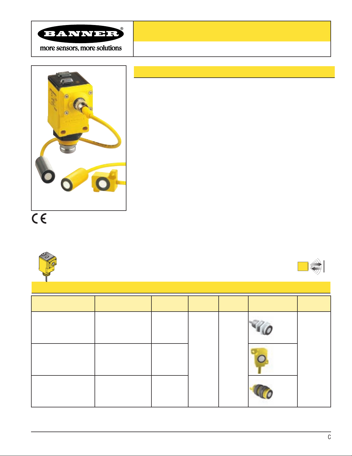
U-GAGE™Analog Q45UR Remote Ultrasonic Sensors
Piezoelectric Analog Proximity Mode Sensors with Push Button or
Remote Programming of Sensing Window
Analog Q45UR Series Features
• Ultrasonic ranging from 50 to 250 mm (2" to 10")
• Push-button TEACH-mode programming of sensing window limits
•Window limits may be set in two ways: by individually setting the near and far
window limits, or by programming a set point to be centered within a 5-mm sensing
window.
• Digital filtering for exceptional immunity to random electrical and acoustic “noise”
• Selectable 0 to 10V dc voltage sourcing or 4 to 20mA current sourcing analog
outputs
• Selectable output slope: positive or negative with increasing target distance
• Wide operating temperature range of -25° to +70°C; all models include temperature
compensation
• Rugged design for use in demanding sensing environments; rated IEC IP67,
NEMA 6P (controller), IP65 (sensor)
• Choose models with integral 2 m (6.5') or 9 m (30') cable, or with Mini-style or
Euro-style quick disconnect fitting
• Choose from 3 remote sensors: 18 mm threaded-barrel models in either stainless
steel or molded PBT polyester, and a molded flat-pak model
• Remote sensors connect to controller via an integral 2 m (6.5') cable
• Input for remote TEACH-mode programming of window limits
• 0.10 mm resolution (0.004")
• Kit includes both controller and sensor; components also sold separately
• Response time is adjustable from 10 to 320 milliseconds
Q45UR Series Ultrasonic Sensor Models
*NOTES:
• 9 m (30') cables are available by adding suffix “W/30” to the model number of any cabled sensor (e.g., Q45UR3LIU64CK W/30).
• A model with a QD connector requires a mating cable; see page 9.
Kit Models
Kit Includes
Controller Model
Controller
Cable*
Controller
Output
Supply
Voltage
Kit Includes Sensor
Model
Sensor
Range
Q45UR3LIU64CK
Q45UR3LIU64CQK
Q45UR3LIU64CQ6K
Q45UR3LIU64C
Q45UR3LIU64CQ
Q45UR3LIU64CQ6
2 m (6.5')
5-Pin Mini QD
5-Pin Euro QD
Selectable
0-10V dc
or
4-20mA
Sourcing
15-24V dc
M18C2.0
Stainless
Steel
Barrel
50 to 250 mm
(2" to 10")
Q45UR3LIU64CKQ
Q45UR3LIU64CQKQ
Q45UR3LIU64CQ6KQ
Q45UR3LIU64C
Q45UR3LIU64CQ
Q45UR3LIU64CQ6
2 m (6.5')
5-Pin Mini QD
5-Pin Euro QD
Q13C2.0
Flat-Pak
Q45UR3LIU64CKS
Q45UR3LIU64CQKS
Q45UR3LIU64CQ6KS
Q45UR3LIU64C
Q45UR3LIU64CQ
Q45UR3LIU64CQ6
2 m (6.5')
5-Pin Mini QD
5-Pin Euro QD
S18C2.0
Molded
Barrel
Ultrasonic
M18C2.0
Stainless
Steel
Barrel
S18C2.0
Molded
Barrel
Q13C2.0
Flat-Pak
D
Printed in USA 01/12 P/N 59323 Rev. C
Page 2
U-GAGE™Analog Q45UR Remote Ultrasonic Sensors
2 P/N 59323 Rev. C
Banner Engineering Corp. • Minneapolis, MN U.S.A.
www.bannerengineering.com • Tel: 763.544.3164
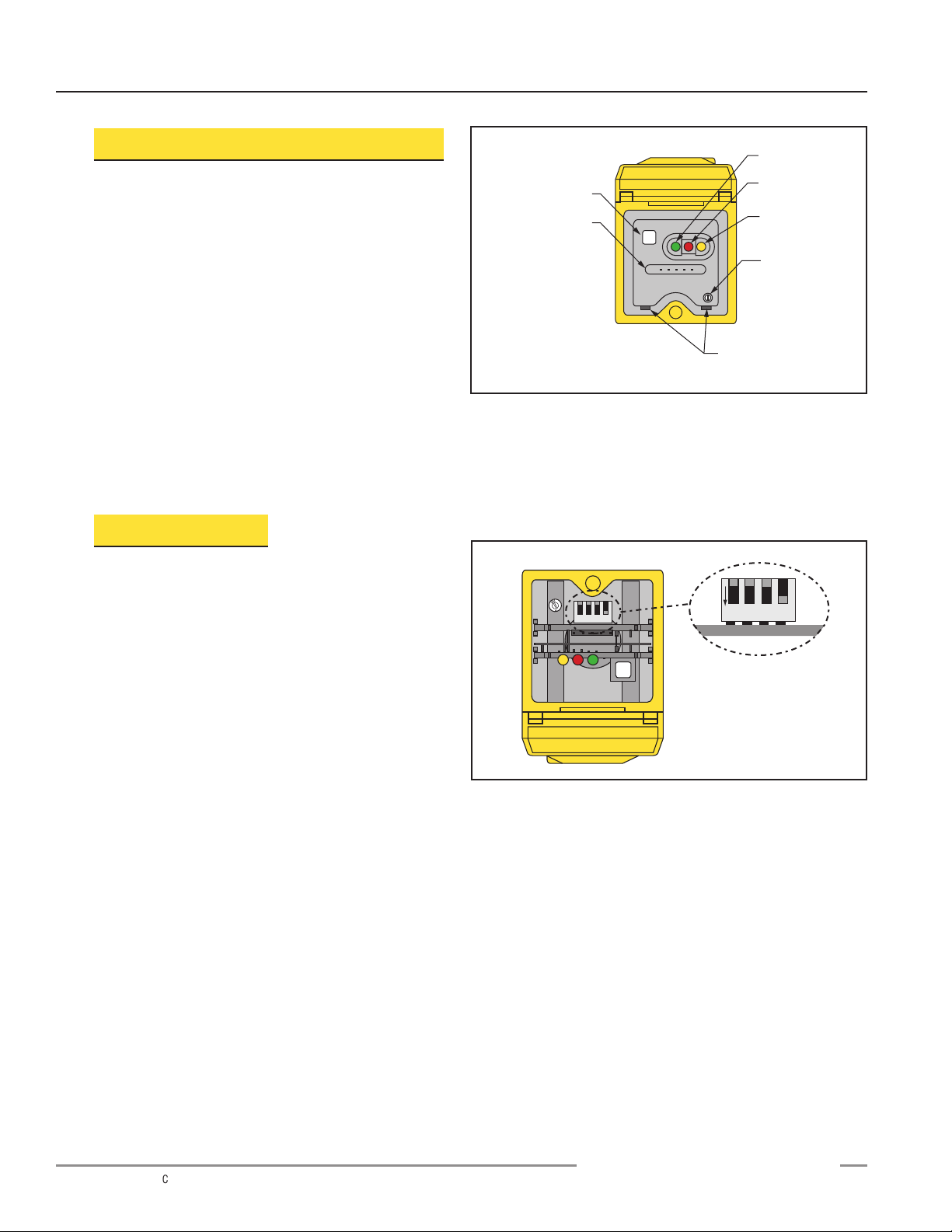
Programming the Sensing Window Limits
The Q45UR controller features a single push button for
programming the sensing window limits (Figure 1). The
window limits may be set in one of two ways:
programming two independent window limits, or defining a
sensing distance set point, which will be centered
automatically within a 5-mm window (specific steps are
described on page 5).
Independent Window Limits: The target is placed at the
desired position to set the first limit, then the second limit
is set using the same procedure. In order to set two
independent limits, the window must at least 5 mm.
Sensing Distance Set Point: The sensor is taught the same
set point for both window limits. The set point is
automatically centered within a 5-mm (0.2") window.
See page 5 for detailed programming instructions.
Status Indicators
Status indicator LEDs are visible through the transparent,
o-ring sealed Lexan®top cover. Indicator function in the
RUN mode is, as follows:
• The green LED is ON steadily whenever power is
applied to the sensor, and flashes to indicate a
current output fault.
• The red LED lights when an echo is received, and
flashes at a rate that is proportional to echo strength.
• The yellow LED lights whenever the target is within
the operating window limits.
The 5-segment moving dot LED indicator displays the relative
position of the target within the programmed sensing window.
The #1 LED flashes when the target is closer than the near
limit. The #5 LED flashes when the target is beyond the far limit.
Figure 1. Analog Q45UR controller features
Figure 2. Analog Q45UR controller programming DIP switches
(factory default settings)
D
Sensing
Window Limits
Programming
Push Button
5-Segment Target
Position Indicator
(N = Near)
Limits
N
1 2 3 4 5
Green Power
Indicator
Red Signal
Indicator
Yel low Output
Indicator
Response
Speed Selector
(10 to 320 ms)
Slots for Inner
Cover Removal
1ON234
See Table Below for
Programming Information
Page 3
Output Response Settings
IMPORTANT: Remove power before making any internal adjustments.
Using the two slots shown in Figure 1, a small flat-blade screwdriver may be used to
lift up and remove the black inner cover to expose the 4-position DIP switch (Figure 2).
Those switches are used to program the following functions:
U-GAGE™Analog Q45UR Remote Ultrasonic Sensors
P/N 59323 Rev. C 3
Banner Engineering Corp. • Minneapolis, MN U.S.A.
www.bannerengineering.com • Tel: 763.544.3164
Switch Function
1
Output Slope
Settings
2
Output Mode
ON = Current output enabled
OFF*= Voltage output enabled
3
Loss of Echo
ON = Min - Max Mode
OFF*= Hold Mode
4
Min - Max
ON* = Default to maximum output value
OFF = Default to minimum output value
ON = Output value increases with distance
OFF*= Output value decreases with distance
Explanation of Programmable Output Functions:
Switch 1: Output Slope Select
ON = (Direct) Output value (voltage or current) increases with increasing
distance of the target from the sensor
OFF* = (Inverse) Output value decreases with increasing distance of the
target from the sensor
Switch 2: Output Mode Select
ON = The 4 to 20mA current output (white wire) is enabled
OFF* = The 0 to 10V dc voltage output (black wire) is enabled
This switch configures the D/A driver to use either the current output or the voltage
output driver.
Switch 3: Loss of Echo Mode Select
ON = Min - Max Mode
OFF* = Hold Mode
This switch determines the output response to the loss of echo. The “Hold Mode”
(Switch 3 Off*) maintains the output at the value which was present at the time of
echo loss. The “Min - Max Mode” (Switch 3 On) drives the output to either the
minimum value (0V or 4mA or the maximum value (10V or 20mA) when the echo is
lost. Minimum or maximum value is selected by Switch 4.
Switch 4: Min - Max Default
ON* = Default to maximum output value at loss of echo
OFF = Default to minimum output value at loss of echo
Switch 4 selects the output response to loss of echo when “Min - Max Mode” is
selected by Switch 3 (see above).
* Factory default setting
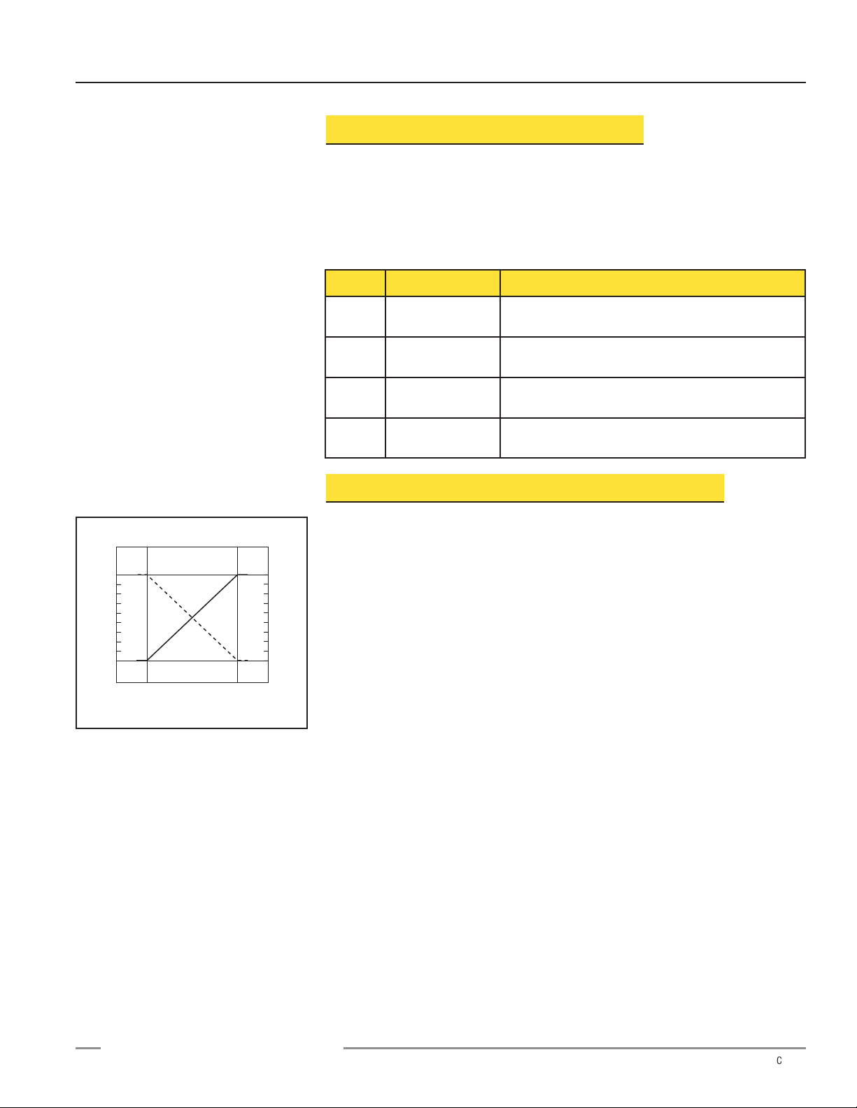
Figure 3. Output as a function of target
position
D
Voltage/Current-Sourcing Models
10
Analog Output (V dc)
0
Near
Window
Positive
Tar get Position
Slope
Far
Window
20
Analog Output (mA)
4
Page 4
U-GAGE™Analog Q45UR Remote Ultrasonic Sensors
4 P/N 59323 Rev. C
Banner Engineering Corp. • Minneapolis, MN U.S.A.
www.bannerengineering.com • Tel: 763.544.3164
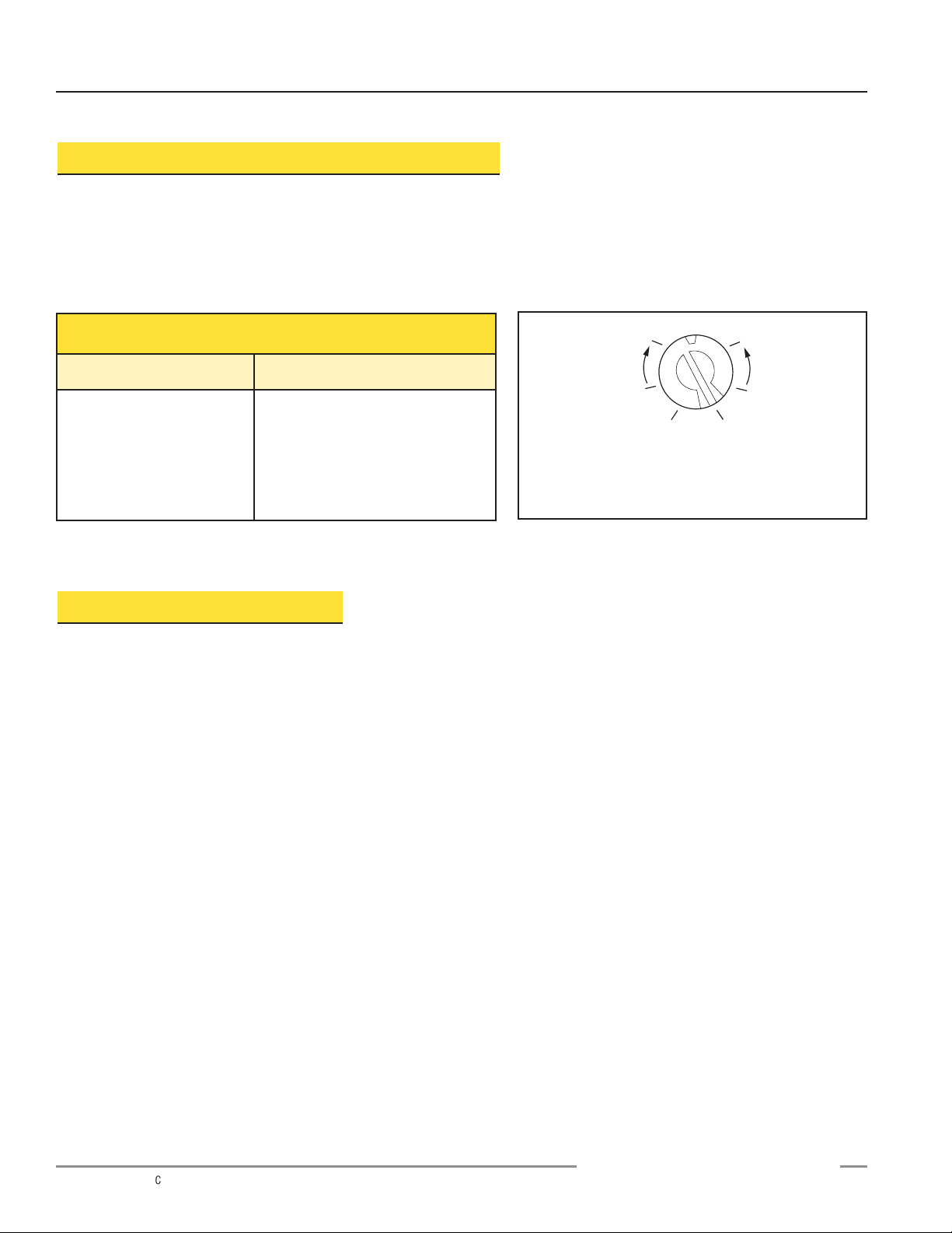
Response Speed Settings
Position Response Speed
1
2
3
4
5
6
10 milliseconds (2 cycles)
20 milliseconds (4 cycles)
40 milliseconds (8 cycles)
80 milliseconds (16 cycles)
160 milliseconds (32 cycles)
320 milliseconds (64 cycles)
Response Speed Adjustment
The speed of the output response is set using the single-turn potentiometer (see Figures
1 and 4). There are six values for response speed, which relate directly to the number of
sensing cycles over which the output value is averaged (see the Response Speed
Settings table, below). The response value is set by aligning the slot of the
potentiometer with one of the marked positions. The positions are identified in Figure 4.
Figure 4. Response adjustment positions
Window Limit Programming
Either the “Limits” push button (located under the transparent top cover) or the
Remote TEACH wire may be used to program the near and the far limits. The near
limit may be set as close as 50 mm (2") and the far limit may be set as far as 250 mm
(10") from the transducer face. Minimum window width is 5 mm (0.2"). Whenever
possible, use the actual target to be sensed when setting the window limits. The
following procedure begins with the sensor in RUN mode.
D
NOTE: This example shows the potentiometer
set at position number 4. There are no
numbers on the actual product label.
+ –
1
2
34
6
5
Page 5

U-GAGE™Analog Q45UR Remote Ultrasonic Sensors
P/N 59323 Rev. C 5
Banner Engineering Corp. • Minneapolis, MN U.S.A.
www.bannerengineering.com • Tel: 763.544.3164
Push Button Indicator Status
Step 1
Access Limit Programming Mode
Push and hold until green indicator turns OFF
(approximately 2 seconds)
Green: Goes OFF
Yellow:ON steady to indicate ready for teaching
first limit
Red: Flashes to indicate strength of echo or is
off if no target is present
Step 2
Set First Limit (Near or Far)
Place the target at the first limit and press the
push button for less than 2 seconds
Green: Remains OFF
Yellow:Flashes at 2 Hz to indicate ready for
teaching second limit
Red: Comes ON steady for a moment, then
resumes flashing to indicate echo strength
Step 3
Set Second Limit (Far or Near)
Place the target at the second limit and press
the push button for less than 2 seconds
If the target is held at the same position for
programming of both limits, the sensor will
establish a 5 mm-wide sensing window,
centered on the target position
Green: Remains OFF, then comes ON steady
(returns to RUN mode)
Yellow:ON steady for a moment, then either ON
or OFF to indicate output state (returns to
RUN mode)
Red: Comes ON steady for a moment, then
resumes flashing to indicate echo strength
(returns to RUN mode)
NOTES:
1) Either the near or far limit may be programmed first.
2) There is a 2 minute time-out for programming of the first limit. If more than 2 minutes elapses, the sensor will return to RUN
mode with the previously programmed limits. There is no time-out between programming of the first and second limit.
3) The programming sequence may be cancelled at any time by pressing and holding the push button for ≥ 2 seconds. The
sensor returns to RUN mode with the previously programmed limits.
4) During limit programming, the 5-segment moving dot indicator displays the relative target position between 50 and 250 mm
(the maximum recommended far limit position is 250 mm).
5) If the target is farther than 250 mm, the 5th segment of the moving dot indicator flashes to indicate that a valid echo is
received, but the target is beyond the recommended 250 mm maximum far limit.
6) If a limit is rejected during either programming step, the sensor will revert to the first limit programming step (end of Step 1
in programming chart). This will be indicated by: Green OFF, Red Flashing to indicate signal strength, and Yellow ON steady.
7) If both limits are accepted, the sensor will return to RUN mode, indicated by: Green goes ON steady.
D
Push and Hold for ≥ 2 Seconds
Push for < 2 Seconds
Target at
First Limit
Push for < 2 Seconds
Target at
Second Limit
Page 6

U-GAGE™Analog Q45UR Remote Ultrasonic Sensors
6 P/N 59323 Rev. C
Banner Engineering Corp. • Minneapolis, MN U.S.A.
www.bannerengineering.com • Tel: 763.544.3164
Remote Window Limit Programming
The yellow wire of the Analog Q45UR may be connected to a
switch or process controller for remote programming of the
sensing window limits. The programming procedure is the
same as for the push button (see page 4).
A remote programming input is generated when +5 to 24V
dc is applied to the yellow wire. The timing diagrams, right,
define the required input pulses.
NOTES:
1) The push button is disabled during remote limit
programming. (The remote programming input is
disabled during push button programming.)
2) Also see the notes regarding window limit programming
on page 4.
Analog Q45UR Series Response Curves
D
Step 1
Access Limit
Programming Mode
Step 2
Set First Limit
(Near or Far)
Step 3
Set Second Limit
(Far or Near)
+5 to 24V dc
<2V dc
(or open circuit)
+5 to 24V dc
<2V dc
(or open circuit)
+5 to 24V dc
<2V dc
(or open circuit)
T T >2 sec
Wait >0.8 seconds
before next input
T
T
0.04 sec <T< 0.8 sec
Wait >2 seconds before next input
0.04 sec <T< 0.8 sec
0.47"12.0 mm
10.0 mm
8.0 mm
6.0 mm
4.0 mm
2.0 mm
50 mm x 50 mm Alum. Plate
10 mm Dia. Alum. Rod
-2.0 mm
0.40"
0.32"
0.24"
0.16"
0.08"
00
-0.08"
Lateral Distance
-4.0 mm
-6.0 mm
-8.0 mm
-10.0 mm
50 mm
2.0"
75 mm
3.0"
100 mm
4.0"
125 mm
5.0"
150 mm
6.0"
175 mm
7.0"
200 mm
8.0"
225 mm
9.0"
-0.16"
-0.24"
-0.32"
-0.40"
-0.47"-12.0 mm
250 mm
10.0"
Target Distance
NOTE: The pattern displayed for the 50 mm x 50 mm Aluminum plate is referenced to the EDGE of the plate.
The pattern displayed for the 10 mm dia. Aluminum rod is referenced to the CENTER of the rod.
Page 7

U-GAGE™Analog Q45UR Remote Ultrasonic Sensors
P/N 59323 Rev. C 7
Banner Engineering Corp. • Minneapolis, MN U.S.A.
www.bannerengineering.com • Tel: 763.544.3164
Analog Q45UR Series Specifications
Indicators
Performance Specifications
* Resolution and linearity are
specified using a 50 mm x
50 mm (2" x 2") aluminum
plate at 22ºC under fixed
sensing conditions using the
4-20 mA output @15V dc.
Range for Nominal Sensing
Position
Near Limit: 50 mm (2") min.
Far Limit: 250 mm (10") max.
Supply Protection Circuitry Protected against reverse polarity and transient voltages
Output Configuration One voltage sourcing and one current sourcing; one or the other output is enabled by internal
programming switch #2 (see page 2).
Output Rating Voltage Sourcing: 0 to 10V dc, 10mA maximum
Current Sourcing: 4 to 20mA, 1 to 500 ohm impedance
Output Protection Circuitry Both outputs are protected against continuous overload and short circuit
Supply Voltage and Current 15 to 24V dc (10% maximum ripple) at 100 mA, exclusive of load
Adjustments Push-button TEACH-mode programming of window limits (see page 2)
The following may be selected by a 4-position DIP switch located on top of the controller, beneath the
transparent acrylic and black inner covers (see page 2)
Switch 1: Output slope: output value increases or decreases with distance
Switch 2: Output mode: current output or voltage output
Switches 3&4: Response to loss of echo: (see page 3)
Response Speed Adjustment: Single-turn potentiometer selects six response values from 10 to 320
milliseconds (see page 3)
Resolution*: 0.2% of sensing distance at 320 ms response
0.4% of sensing distance at 10 ms response
Linearity*: ±1.0 mm (0.04") with 100 to 200 mm sensing window
±2.0 mm (0.08") with 50 to 250 mm sensing window
Temperature stability: ±0.03% of sensing distance per ºC from 0 to 50ºC (±0.05% per ºC over remainder
of operating temperature)
Ultrasonic beam angle: ±3.5º
Also see response curve on page 5
Minimum target size is specified as a 10 x 10 mm (0.4" x 0.4") aluminum plate (at any point within the 50 to
150 mm sensing range).
Construction Controller: Molded thermoplastic polyester housing, o-ring sealed transparent acrylic top cover, and
stainless steel hardware
Sensors: M18C2.0: Stainless steel M18 threaded barrel housing and jam nuts, ULTEM®polyetherimide
front cover, ceramic transducer, TEXIN
®
polyurethane rear cover
S18C2.0: Thermoplastic polyester S18 threaded barrel housing and jam nuts, ULTEM
®
polyetherimide front cover, ceramic transducer, TEXIN®polyurethane rear cover
Q13C2.0: Molded 30% glass reinforced thermoplastic polyester housing, ceramic transducer,
fully epoxy-encapsulated
Environmental Rating Controller: IEC IP67; NEMA 6P
Sensor: IEC IP65; NEMA 4
Three status LEDs:
Green ON steady = Power to controller is ON
Green flashing = Current output fault detected (indicates that the 4-20 mA current path to ground
has been opened)
Yellow ON steady =Target is sensed within the window limits (Yellow LED also indicates
programming status during setup mode)
Red flashing = Relative strength of received echo
5-segment moving dot LED indicates the position of the target within the sensing window
ULTEM®is a registered trademark of General Electric
TEXIN
®
is a registered trademark of Bayer Corporation
D
Page 8

U-GAGE™Analog Q45UR Remote Ultrasonic Sensors
8 P/N 59323 Rev. C
Banner Engineering Corp. • Minneapolis, MN U.S.A.
www.bannerengineering.com • Tel: 763.544.3164
Vibration and
Mechanical Shock
Application Notes
All models meet Mil. Std. 202F requirements. Method 201A Vibration: 10 to 60Hz max., double amplitude
0.06" (maximum acceleration 10G). Method 213B conditions H & I (Shock: 75G with unit operating; 100G
for non-operation). Also meets IEC 947-5-2 requirements: 30G, 11 ms duration, half sine wave.
Certifications
Connections Controller: 2m (6.5') or 9 m (30') attached cable, or 5-pin Mini-style or Euro-style quick-disconnect fitting
Sensor: 2m (6.5') attached PVC cable terminated with 4-pin Euro-style quick-disconnect fitting for
connection to controller
The controller has non-volatile memory which remembers the last sensing window setting if power is
removed and later reapplied.
The sensing window may be programmed via the Remote Teach input (see hookup diagrams).
Acceptable target angle is within ±5º of normal for a smooth, flat target; target rotation does affect the
apparent target location with respect to the sensor.
Q45UR Controller with 5-Pin
Mini-Style QD
(“Q” Model Suffix)
Q45UR Controller with
Attached Cable
Q45UR Controller with 5-Pin
Euro-Style QD
(“Q6” Model Suffix)
5-Pin Mini-Style Pin-Out
(Cable Connector Shown)
5-Pin Euro-Style Pin-Out
(Cable Connector Shown)
Q45UR Series Controller Hookups
bn
wh
bu
+
–
bk
ye or gy
Load
15-24V dc
Remote Teach
(+5-24V dc)
Load
shield*
4 to 20 mA
0 to 10V
bn
wh
bu
+
–
bk
ye
Load
Load
15-24V dc
Remote Teach
(+5-24V dc)
shield*
4 to 20 mA
0 to 10V
bn
wh
bu
+
–
bk
gy
Load
Load
15-24V dc
Remote Teach
(+5-24V dc)
shield*
4 to 20 mA
0 to 10V
Operating Temperature Controller and sensor: -25° to +70°C (-13° to +158°F)
Maximum relative humidity: 85% (non-condensing)
Analog Q45UR Series Specifications, continued
* It is recommended that the shield wire be
connected to earth ground or dc common.
D
White Wire
Brown Wire
Yellow Wire
Black Wire
Blue Wire
White Wire
Brown Wire
Black Wire
Blue Wire
Gray Wire
Page 9

U-GAGE™Analog Q45UR Remote Ultrasonic Sensors
P/N 59323 Rev. C 9
Banner Engineering Corp. • Minneapolis, MN U.S.A.
www.bannerengineering.com • Tel: 763.544.3164
Q45UR Controller with Attached Cable
Q45UR Controller with
5-Pin Mini-Style QD
(“Q” model Suffix)
Q45UR Controller with
5-Pin Euro-Style QD
(“Q6” model Suffix)
Q45UR Series Controller Dimensions
Remote Sensor Dimensions Accessories
Quick-disconnect (QD) Cables
5-Pin Euro-style
Straight
with shield
MQDEC2-506
MQDEC2-515
MQDEC2-530
2 m (6.5')
5 m (15')
9 m (30')
Description Model Length Connector
5-Pin Mini-style
with shield
MBCC2-506
MBCC2-512
MBCC2-530
2 m (6.5')
4 m (12')
9 m (30')
5-Pin Euro-style
Right-angle
with shield
MQDEC2-506RA
MQDEC2-515RA
MQDEC2-530RA
2 m (6.5')
5 m (15')
9 m (30')
M18C2.0 and S18C2.0 Sensors
Q13C2.0 Sensors
D
Transparent Cover (Gasketed)
View: Sensing Status
Output Load Status
Power
Open to Access:
Push Button for
Programming of Sensing
Window Limits
Response Speed
Selector
44.5 mm
(1.75")
69.0 mm
(2.72")
87.6 mm
(3.45")
Internal Thread
(1/2–14NPSM)
External Thread
M30 X 1.5
60.5 mm
(2.38")
30.0 mm
(1.18")
ø 6.1 (0.24")
2m (6.5') Cable
Hex Nut Supplied
50.8 mm
(2.00")
6.4 mm (0.25")
4.5 mm (#10) Screw
Clearance (2)
7.1 mm
(0.28")
Tra ns ducer
Centerline
14.0 mm (0.6")
15.0 mm (0.6")
Temperature
2 m
(6.5') Cable
45.0 mm
(1.14")
37.0 mm
(1.46")
Compensation Probe
Jam Nuts
(2 Provided)
27.5 mm
(1.08")
20.7 mm
20.7 mm
(0.81")
(0.81")
Temperature
Compensation
Probe
(Internal)
Ultrasonic
Transducer
2x ø3.5 mm
(0.14")
27.5 mm
(1.08")
3.6 mm
3.6 mm
(0.14")
(0.14")
18 x 1 mm
Thread
Ultrasonic
Transducer
12.0 mm
(0.47")
61 mm max.
(2.4")
44 mm max.
(1.7")
38 mm max.
M12 x 1
ø15 mm
(0.6")
(1.5")
7/8-16UN-2B
ø28 mm
(1.1")
ø15 mm
(0.6")
M12 x 1
38 mm max.
(1.5")
Page 10

U-GAGE™Analog Q45UR Remote Ultrasonic Sensors
10 P/N 59323 Rev. C
Banner Engineering Corp. • Minneapolis, MN U.S.A.
www.bannerengineering.com • Tel: 763.544.3164
Mounting Brackets for Q45UR Series Controllers
SMB30MM
SMB30S
• 30 mm swivel, black PBT polyester bracket
• Stainless steel mounting hardware included
• 30 mm, 11-gauge stainless steel bracket
• Curved mounting slots for versatility and orientation
SMB30C
• 30 mm split clamp, black PBT polyester bracket
• Stainless steel mounting hardware included
D
63.5 mm
(2.50")
50.8 mm
25.4 mm
(1.00")
(2.00")
Not Shown:
(2) M5 x 0.8 x 60 mm
screws are supplied for
clamping bracket together
43.2 mm
(1.70")
M5 x 0.8
x 30 mm
Screw (2)
12.2 mm
(0.48")
82.5 mm
(3.25")
25.4 mm
(1.00")
63.0 mm
(2.48")
13.5 mm (0.53")
56.0 mm
(2.20")
45.0 mm
(1.77")
31.5 mm
(1.24")
2.5 mm
(0.10")
13 mm
Nut Plate
M5 x 0.8
x 80 mm
Screw (2)
(0.5")
57.2 mm
(2.25")
R 25.4 mm
ø30.1 mm
(1.19")
ø 6.4 mm
(0.25" dia.)
(1.00")
25.4 mm
(1.00")
35.1 mm
(1.38")
35.1 mm
(1.38")
69.9 mm
(2.75")
7.1 mm
.28 x 90° (2 Slots)
57.2 mm
(2.25")
Page 11

U-GAGE™Analog Q45UR Remote Ultrasonic Sensors
P/N 59323 Rev. C 11
Banner Engineering Corp. • Minneapolis, MN U.S.A.
www.bannerengineering.com • Tel: 763.544.3164
Mounting Brackets for M18C2.0 and S18C2.0 Sensors
SMB18S
m
5
SMB18A
• 11-gauge, stainless steel right-angle bracket
• Curved mounting slot for versatility and orientation
• 18 mm swivel, black PBT polyester bracket
• Stainless steel mounting hardware included
SMB18C
• 18 mm split clamp black PBT polyester bracket
• Stainless steel mounting hardware included
D
44.5 mm
(1.75")
13.0 mm (0.50")
* Use 4 mm (#8) screws
to mount bracket.
Drill screw holes
24.2 mm (0.95") apart.
R 24.2 mm
(0.95")
ø 4.6 mm*
(0.18")
30°
30 mm
(1.2")
4.6 mm*
(0.18")
7.6 mm
(0.30")
18.5 mm
(0.73")
25.4 mm
(1.00")
46 mm
(1.8")
41 mm
(1.6")
46.0 mm
(1.81")
36.0 mm
(1.42")
25.4 mm
(1.00")
2.5 mm
(0.10")
10.9 mm
(0.43")
Spacer
(If Required)
Nut Plate
M5 x 0.8
x 60 mm
Screw (2)
6.4
(0.2
42.4 mm
(1.67")
14.0 mm
(0.55")
40.0 mm
(1.60")
30.0 mm
(1.18")
21.1 mm
(0.83")
2.5 mm
(0.10")
13 mm
Nut Plate
M5 x 0.8
x 60 mm
Screw (2)
(0.5")
Page 12

U-GAGE™Analog Q45UR Remote Ultrasonic Sensors
Banner Engineering Corp., 9714 Tenth Ave. No., Mpls, MN 55441 • Ph: 763.544.3164 • www.bannerengineering.com • sensors@bannerengineering.com
P/N 59323 Rev. D
WARNING . . . Not To Be Used for Personnel Protection
Never use these products as sensing devices for personnel protection. Doing so could lead to serious injury or death.
These sensors do NOT include the self-checking redundant circuitry necessary to allow their use in personnel safety
applications. A sensor failure or malfunction can cause either an energized or de-energized sensor output condition. Consult your current
Banner Safety Products catalog for safety products which meet OSHA, ANSI and IEC standards for personnel protection.
!
Banner Engineering Corp Limited Warranty
Banner Engineering Corp. warrants its products to be free from defects in material and workmanship for one year
following the date of shipment. Banner Engineering Corp. will repair or replace, free of charge, any product of its
manufacture which, at the time it is returned to the factory, is found to have been defective during the warranty
period.This warranty does not cover damage or liability for misuse, abuse, or the improper application or installation of
the Banner
product.
THIS LIMITED WARRANTY IS EXCLUSIVE AND IN LIEU OF ALL OTHER WARRANTIES WHETHER EXPRESS OR
IMPLIED (INCLUDING, WITHOUT LIMITATION, ANY WARRANTY OF
MERCHANTABILITY OR FITNESS FOR A PARTICULAR PURPOSE), AND WHETHER ARISING UNDER COURSE
OF PERFORMANCE, COURSE OF DEALING OR TRADE USAGE.
This Warranty is exclusive and limited to repair or, at the discretion of Banner Engineering Corp., replacement. IN NO
EVENT SHALL BANNER ENGINEERING CORP. BE LIABLE TO BUYER
OR ANY OTHER PERSON OR ENTITY FOR ANY EXTRA COSTS, EXPENSES, LOSSES, LOSS OF PROFITS, OR
ANY INCIDENTAL, CONSEQUENTIAL OR SPECIAL DAMAGES RESULTING
FROM ANY PRODUCT DEFECT OR FROM THE USE OR INABILITY TO USE THE PRODUCT, WHETHER ARISING
IN CONTRACT OR WARRANTY, STATUTE, TORT, STRICT LIABILITY,
NEGLIGENCE, OR OTHERWISE.
Banner Engineering Corp. reserves the right to change, modify or improve the design of the product without assuming
any obligations or liabilities relating to any product previously
manufactured by Banner Engineering Corp.
 Loading...