

Page 1
7.6 (0.30)
8.3 (0.33)
0 (0)
15-16
25-26
33-34
8.8 (0.35)
21.5 (0.85)
mm (in)
Engaged
Disengaged
Safety
Safety
Monitor
25 26
33 34
15 16
25 26
33 34
15 16
4.3 (0.17)
4 (0.16)
0 (0)
4.4 (0.18)
21.5 (0.85)
mm (in)
Engaged
Disengaged
Safety
Monitor
11-12
23-24
23 24
11 12
23 24
11 12
4.5 (0.18)
4.2 (0.17)
0 (0)
21.5 (0.85)
mm (in)
Engaged
Disengaged
Safety
Monitor
11-12
21-22
21 22
11 12
21 22
11 12
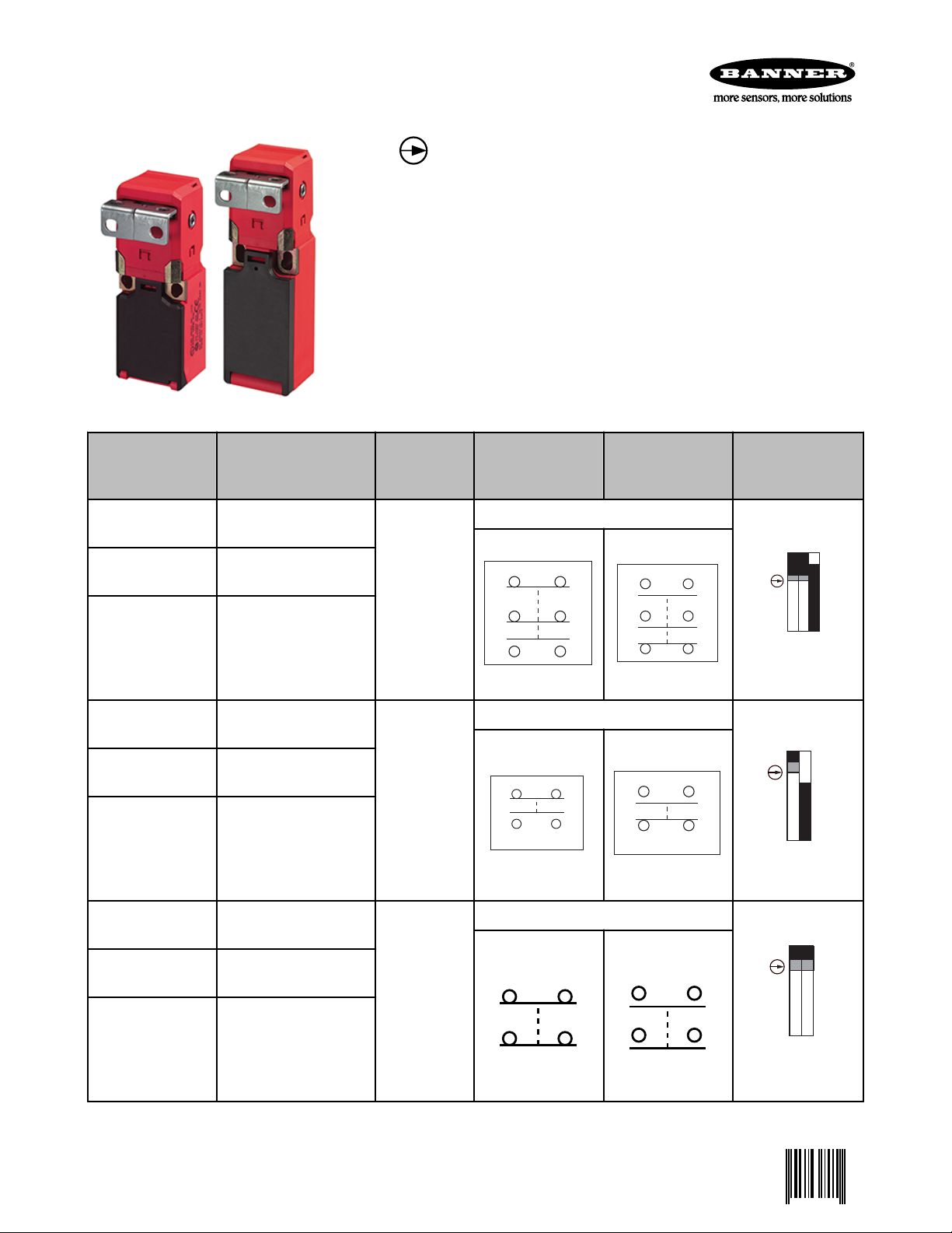
Limit-Switch Style Machine Safety Switches
0 059622 4
SI-LS83 and SI-LS100 Series Limit Switch Style – 83 mm and 100 mm
•
Positive opening safety contacts (IEC 60947-5-1) (not dependent on
springs)
• Limit switch design (EN 50047)
• Mechanically-coded actuators use two independent operating elements to mini-
mize intentional tampering or defeat
• Rotating head allows actuator engagement from four sides or four top positions;
no tools are required to rotate head
• Low-profile design for limited space requirements; only 30.5 mm (1.3") depth
• Tough, glass-reinforced thermoplastic housing; metal actuator
• Choice of two in-line actuators or a flexible actuator
• Insulated device (IEC 60947-5-1)
Kit Model * Actuator Type *
SI-LS100SF
SI-LS100SRAF
SI-QS-SSA-2 Straight
Rigid In-Line
SI-QS-SSA-3 Right-angle
In-Line
SI-LS100MRFF (Direct replacement for
models SILS100MRHF and
SI-QS-SSU Flexible InLine
SI-LS100MRVF)
SI-LS83SD
SI-LS83SRAD
SI-QS-SSA-2 Straight
Rigid In-Line
SI-QS-SSA-3 Right-angle
In-Line
SI-LS83MRFD (Direct replacement for
models SILS83MRHD and SI-
SI-QS-SSU Flexible InLine
LS83MRVD)
Interlock
Body *
SI-LS100F
SI-LS83D
Contact Configuration (Actuator Engaged)
Contact Configuration (Actuator Removed)
Two N.C. and One N.O. Contact
One N.C. and One N.O. Contact
Switching Diagrams
SI-LS83SE
SI-LS83SRAE
SI-LS83MRFE (Direct replacement for
models SILS83MRHE and SILS83MRVE)
P/N 059622 Rev. G 3/25/2013
SI-QS-SSA-2 Straight
Rigid In-Line
SI-QS-SSA-3 Right-angle
In-Line
SI-QS-SSU Flexible InLine
Two N.C. Contacts
SI-LS83E
Page 2

Limit-Switch Style Machine Safety Switches
Switching Diagram Key
Contacts: Open Closed Transition
This symbol ( ) is used in the switching diagrams to identify the point in actuator travel where the normally closed safety contact is
fully open.
* A kit contains an interlock and actuator. Individual interlock bodies or actuators are for replacement purposes only.
Important Information Regarding the Use of Safety Switches
In the United States, the functions that Banner safety switches are intended to perform are regulated by the Occupational Safety and
Health Administration (OSHA). Whether or not any particular safety switch installation meets all applicable OSHA requirements depends
upon factors that are beyond the control of Banner Engineering Corp. These factors include the details of how the safety switches are
applied, installed, wired, operated, and maintained.
Banner Engineering Corp. has attempted to provide complete application, installation, operation, and maintenance instructions. This information is found in the instruction manual packaged with each safety switch. In addition, we suggest that any questions regarding the
use or installation of safety switches be directed to the factory applications department at the telephone numbers or address shown
below.
Banner Engineering Corp. recommends that safety switches be applied according to the guidelines set forth in international (ISO/IEC)
standards listed below. Specifically, Banner Engineering Corp. recommends application of these safety switches in a configuration which
meets safety category 4, per ISO 13849 (EN954-1).
In addition, the user of Banner safety switches has the responsibility to ensure that all local, state, and national laws, rules, codes, and
regulations relating to the use of Banner safety switches in any particular application are satisfied. Extreme care is urged that all legal
requirements have been met and that all installations and maintenance instructions are followed.
Application Assistance
Toll Free: 1-888-3-SENSOR (1-888-373-6767)
Email: sensors@bannerengineering.com
9714 Tenth Avenue North
Minneapolis, MN 55441
U.S. Regulations Applicable to Use of Banner Safety Switches
OSHA Code of Federal Regulations: Title 29, Parts 1900 to 1910
Available from: Superintendent of Documents, Government Printing Office, P.O. Box 371954, Pittsburgh, PA 15250-7954, Tel:
202-512-1800
U.S. Standards Applicable to Use of Banner Safety Switches
ANSI B11 Standards for Machine Tools Safety
Contact: Safety Director, AMT – The Association for Manufacturing Technology, 7901 Westpark Drive, McLean, VA 22102, Tel.:
703-893-2900
Applicable European and International Standards
ISO/TR 12100-1 (EN 292-1 & -2) Safety of Machinery – Basic Concepts, General Principles for Design
ISO 13852 (EN 294) Safety of Machinery—Safety Distances to Prevent Danger Zones Being Reached by the Upper Limbs
ISO 13853 (EN 811) Safety of Machinery—Safety Distances to Prevent Danger Zones Being Reached by the Lower Limbs
ISO 13849-1 (EN 954-1) Safety-Related Parts of Control Systems
ISO 13855 (EN 999) The Positioning of Protective Equipment in Respect to Approach Speeds of Parts of the Human Body
ISO 14119 (EN 1088) Interlocking Devices Associated with Guards – Principles for Design and Selection
IEC 60204-1 Electrical Equipment of Machines Part 1: General Requirements
IEC 60947-5-1 Low Voltage Switchgear – Electromechanical Control Circuit Devices
Contact: Global Engineering Documents, 15 Inverness Way East, Englewood, CO 80112-5704, Tel.: 800-854- 7179
2 www.bannerengineering.com - tel: 763-544-3164 P/N 059622 Rev. G
Page 3
1.
2.
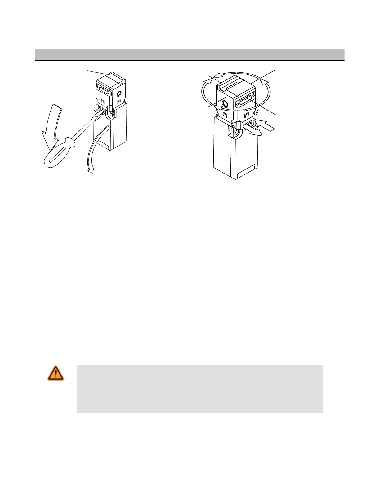
Cover for
Unused Entry
90°
1. Pull holding clamp
2. Turn actuator head
3. Push holding clamp
270°
180°
0°
1.
3.
2.
Limit-Switch Style Machine Safety Switches
Overview
Easy Access Rotating the Actuator Head
The wiring chamber is accessed via a hinged door. Simply insert a
flat-blade screwdriver, as shown, and pry gently down to open.
The actuator head may be rotated in 90° increments to create
eight possible actuator engagement locations. To rotate the head,
pull the holding clamp forward, rotate the head to the desired position, and push the holding clamp back in to lock.
Mechanical Installation
All mounting hardware is supplied by the user. Fasteners must be of sufficient strength to guard against breakage. Use of permanent
fasteners or locking hardware is recommended to prevent loosening or displacement of the actuator and the switch body. The mounting
holes in the switch body and the actuator accept M5 screws (see Dimensions on page 6).
Position the switch, with its actuator fully engaged, in the mounting location and mark the mounting holes. Drill the required holes and
fasten the switch body and the actuator in place. After the mounting hardware is secure, check the actuator-switch engagement for misalignment and binding.
IMPORTANT:
1. A safety switch must be installed in a manner which discourages tampering or defeat. Mount each switch to prevent bypassing of
the switching function at the terminal chamber.
2. A switch and its actuator must never be used as a mechanical stop.
Electrical Installation
WARNING: Hazard Point
It must not be possible for personnel to reach any hazard point through an opened guard (or any
opening) before hazardous machine motion has completely stopped.
Please reference OSHA CFR 1910.217 and ANSI B11 standards for information on determining safety
distances and safe opening sizes for your guarding devices.
P/N 059622 Rev. G www.bannerengineering.com - tel: 763-544-3164 3
Page 4

Safety
Switch
#1
Safety
Switch
#2
Input
Channel
#1
Input
Channel
#2
2-channel Safety Module
(2-channel E-stop Module
2-channel Gate Monitor Module, etc.)
Single gate
or guard
Limit-Switch Style Machine Safety Switches
CAUTION: Electrical Installation
Two safety switches must be used for each interlock guard to achieve control reliability or Safety
Category 4 (per ISO 13849-1, EN 954-1) of a machine stop circuit. Use of only one safety switch per
interlock guard is not recommended.
In addition, normally-closed safety contacts from each of the two safety switches should be connected to
the two separate inputs of a 2-channel safety module or safety interface. This is required to provide monitoring for safety switch contact failure, and to provide the necessary reset routine, as required by IEC
60204-1 and NFPA 79 machine safety standards.
WARNING: Series Connection of Safety Interlock Switches
Monitoring multiple guards with a series connection of safety interlock switches may result in a failure being masked or not detected at all. When such a configuration is used, periodic checks must be performed
regularly to verify proper operation. All failures must be immediately corrected ( e.g. immediately replacing
a failed switch), or the loss of the safety stop signal or an inappropriate reset could lead to serious injury or
death.
Access to the Wiring Chamber
The wiring chamber is accessed via the hinged door (see Overview on page 3). The SI-LS83 switches have a wire entrance of M16 x 1.5.
The SI-LS100 models have a wire entrance of M20 x 1.5. All models come with an adaptor to convert to 1/2"–14 NPT. M16 x 1.5 and
M20 x 1.5 cable glands are available, see Accessories on page 7 .
Connection to a Machine
As illustrated in Figure 1. Switch Wiring to Safety Module on page 4, a normally closed safety contact (i.e., a safety contact that is
closed when the actuator is engaged) from each of two safety switches per interlocked guard must connect to a 2-channel safety module
or safety interface in order to achieve a control reliable interface to the master stop control elements of a machine. Examples of appropriate safety modules include 2-channel emergency stop (E-stop) safety modules and gate monitor safety modules.
NOTE: Refer to the installation instructions provided with the safety module for information regarding the interface of the safety module to the machine stop control elements.
Figure 1. Switch Wiring to Safety Module
Connect two redundant safety switches per interlock guard to an
appropriate 2-channel input safety module.
Two functions of the safety module or safety interface are to:
1. provide a means of monitoring the contacts of both safety switches for contact failure, and to prevent the machine from restarting if
either switch fails; and
4 www.bannerengineering.com - tel: 763-544-3164 P/N 059622 Rev. G
Page 5

Limit-Switch Style Machine Safety Switches
2. provide a reset routine after closing the guard and returning the safety switch contacts to their closed position. This prevents the
controlled machinery from restarting by simply reinserting the safety switch actuators. This necessary reset function is required by
ANSI B11 and NFPA 79 machine safety standards.
Use only a positively driven, normally closed safety contact from each switch for connection to the safety module. The normally open
contact may be used for control functions that are not safety-related. A typical use is to communicate switch status to a process controller. Refer to the installation instructions provided with the safety modules for more information regarding the interface of the safety module to the machine stop control elements.
Periodic Checks
Safety switches should be checked at each shift change or machine setup by a designated person for:
1. Breakage of the switch body or actuator,
2. Good alignment and full engagement of the actuator with the receptor,
3. Confirmation that the safety switch is not being used as an end stop,
4. Loosening of the switch or actuator mounting hardware, and
5. Verification that it is not possible to reach any hazard point through an opened guard (or any opening) before hazardous machine
motion has completely stopped.
In addition, a qualified person should check for the following on a periodic schedule determined by the user based upon the severity of
the operating environment and the frequency of switch actuations:
1. Check the wiring chamber for signs of contamination.
2. Check the contacts for signs of deterioration or damage.
3. Inspect the electrical wiring for continuity and damage.
4. Verify the wiring conforms to the instructions given in this datasheet.
A designated person is identified in writing by the employer as being appropriately trained to perform a specified checkout procedure. A
qualified person possesses a recognized degree or certificate or has extensive knowledge, training, and experience to be able to solve
problems relating to the safety switch installation (ANSI B30.2).
Repairs
Do not attempt any repairs to the Module. It contains no field-replaceable components. Return it to the factory for warranty repair
or replacement by contacting Banner Factory Application Engineering. They will attempt to troubleshoot the system from your description
of the problem. If they conclude a component is defective, they will issue a return merchandise authorization (RMA) number for your
paperwork and give you the proper shipping address.
Pack the Module carefully. Damage that occurs in return shipping is not covered by warranty.
CAUTION: Abuse of Module After Failure
If an internal fault has occurred and the Module will not reset, do not tap, strike, or otherwise attempt to
correct the fault by a physical impact to the housing. An internal relay may have failed in such a man-
ner that its replacement is required.
If the Module is not immediately replaced or repaired, multiple simultaneous failures may accumulate such that the safety function can not be guaranteed.
Specifications
Contact Rating
10A @ 24V ac, 10A @ 110V ac, 6A @ 230V ac; 6A @
24V dc
2.5 kV max. transient tolerance
NEMA A300 P300
Contact Material
Silver-nickel alloy
Maximum Switching Speed
30 operations per minute
European Rating
Utilization categories: AC15 and DC13 (IEC 60947-5-1)
Switches with 1 and 2 contact pairs: Ui = 500V ac; Ith =
10 A
Switches with 3 contact pairs: Ui = 400V ac; Ith = 5A
40-60 Hz
Ue Ie/AC-15 Ie/DC-13
P/N 059622 Rev. G www.bannerengineering.com - tel: 763-544-3164 5
Page 6

M5
Clearance
16.0 mm
(0.64")
30.5 mm
(1.21")
4.0 mm
(0.16")
8.0 mm
(0.32")
38.0 mm
(1.50")
62.0 mm
(2.46")
100.0 mm
(3.98")
30.0 mm
(1.19")
20 mm
(0.79")
22 mm
(0.87")
M20 x 1.5
(0.06")
1/2"-14 NPT
Adapter is Supplied
2.0 mm
(0.08")
5.5 mm
(0.22")
38.0 mm
(1.50")
45.0 mm
(1.79")
30.0 mm
(1.19")
M16 x 1.5
(0.06")
1/2"-14 NPT
Adapter is Supplied
M5
Clearance
22 mm
(0.87")
27.0 mm
(1.07")
83.0 mm
(3.30")
11.0 mm
(0.44")
23 mm
(0.91")
Limit-Switch Style Machine Safety Switches
Maximum Actuator Speed
1 m/second (39"/second)
Minimum Actuator Engagement Radius
In-line actuators: 150 mm (6 inches)
Flexible actuators: 50 mm (2 inches) in all directions
Actuator Extraction Force
12 Newtons (2.6 lbf)
Short Circuit Protection
6 amp Slow Blow, 10 amp Fast Blow. Recommended
external fusing or overload protection.
Construction
Glass fiber-reinforced polyamide thermoplastic housing; UL 94-V0 rating
Weight
SI-LS83 models: 0.12 kg (0.26 lb)
SI-LS100 models: 0.13 kg (0.29 lb)
Environmental Rating
IEC IP65
NOTE: Addition of a No. 3 x 1/4" screw (max) to the
wiring access door increases sealing to IEC IP67,
NEMA 4X
Operating Conditions
Temperature: -30° to +80° C (-22° to +176° F)
40-60 Hz
V A A
24 10 6
110 10 1
230 6 0.4
Mechanical Life
1 million operations
Wire Connections
Stranded and solid: 20 AWG (0.5 mm2) to 18 AWG (1.0
mm2) for one wire
Stranded: 20 AWG (0.5 mm2) to 18 AWG (1.0 mm2) for
two wires
Cable Entry
SI-LS83 models: M16 x 1.5 threaded entrance
SI-LS100 models: M20 x 1.5 threaded entrance
Adapter supplied with each switch to convert to ½"–14
NPT threaded entrance.
Certifications
Dimensions
Model SI-LS-100F Interlock Body Model SI-LS-83x Interlock Body
6 www.bannerengineering.com - tel: 763-544-3164 P/N 059622 Rev. G
Page 7

6.5 mm
(0.26")
11.3 mm
(0.45")
5.0 mm
(0.20")
8.5 mm
(0.34")
12.5 mm
(0.50")
6.3 mm
(0.25")
M4 (#8) Clearance
32.0 mm
(1.27")
19.0 mm
(0.76")
21.0 mm
(0.83")
30.0 mm
(1.19")
Top View Side View
Switch and Actuator
6.5 mm
(0.26")
11.3 mm
(0.45")
5.0 mm
(0.20")
4.3 mm
(0.17")
30.0 mm
(1.19")
19.0 mm
(0.76")
21.0 mm
(0.83")
30.0 mm
(1.19")
M4 (#8) Clearance
Top View
Side View
Switch and Actuator
40.0 mm
(1.57")
52.0 mm
(2.04")
18.0 mm
(0.72")
20.0 mm
(0.78")
Switch and Actuator Top View
M16 x 1.5
19.0 mm
(0.75")
34.0 mm
(1.34")
M20 x 1.5
25.0 mm
(0.98")
37.0 mm
(1.46")
24.0 mm
(0.94")
25.0 mm
(0.98")
M16 x 1.5
1/2"-14 NPT
Internal Thread
Limit-Switch Style Machine Safety Switches
Model SI-QS-SSA-3 Right-Angle Actuator Model SI-QS-SSA-2 In-line Actuator Model SI-QS-SSU Flexible Actuator
Accessories
Cable Glands
Model Size For Cable Diameter Dimensions Used With
SI-QS-CGM16 M16 × 1.5 Plastic
Model Size For Cable Diameter Dimensions Used With
SI-QS-CGM20 M20 × 1.5 Plastic
Conduit Adapters
One conduit adapter is supplied with each switch.
Model Size Thread Conversion Dimensions Used With
SI-QS-M16
P/N 059622 Rev. G www.bannerengineering.com - tel: 763-544-3164 7
½"-14 NPT Plastic
3.0 to 8.0 mm (0.12
to 0.31 inches)
5.0 to 12.0 mm (0.20
to 0.47 inches)
M16 x 1.5 to ½"-14
NPT
SI-QS75 Safety Interlock
Switches
SI-LS83 Safety Interlock
Switches
SI-QS90 Safety Interlock
Switches
SI-LS100 Safety Interlock
Switches
SI-LS31 Safety Interlock
Switches
SI-LS42 Safety Interlock
Switches
RP-LS42 Rope Pull Switches
SI-QS75 Safety Interlock
Switches
SI-LS83 Safety Interlock
Switches
Page 8

25.0 mm
(0.98")
M20 x 1.5
24.0 mm
(0.94")
1/2"-14 NPT
Internal Thread
Limit-Switch Style Machine Safety Switches
Model Size Thread Conversion Dimensions Used With
SI-QS90 Safety Interlock
Switches
SI-LS100 Safety Interlock
Switches
SI-LS31 Safety Interlock
Switches
SI-QS-M20
½"-14 NPT Plastic
M20 x 1.5 to ½"-14
NPT
SI-LS42 Safety Interlock
Switches
RP-LS42 Rope Pull Switches
Replacement Actuators
Type Model Application
SI-QS-SSA-3 (Inline)
SI-QS-SSA-2 (Inline)
SI-QS-SSU (Flexible)
SI-QS-SSUA (Adapter
Plate)
For doors or covers with a radius of 150 mm (6"), or greater. (Pictured
from left to right: -SSA-3 and -SSA-2).
For hinged doors with a radius of 50 mm (2") or greater. Flexes in four
directions. The actuator is die-cast steel.
Clear acrylic adapter plate used to retrofit SI-QS-SSU to older flexible
actuators SI-QS-HMA and SI-QS-VMA.
WARNING: Spare Actuators
Spare actuators must NEVER be used to bypass or otherwise defeat the protective function of a safety
switch. To do so may create an unsafe situation which could lead to serious injury or death.
Banner Engineering Corp Limited Warranty
Banner Engineering Corp. warrants its products to be free from defects in material and workmanship for one year following the date of
shipment. Banner Engineering Corp. will repair or replace, free of charge, any product of its manufacture which, at the time it is returned
to the factory, is found to have been defective during the warranty period. This warranty does not cover damage or liability for misuse,
abuse, or the improper application or installation of the Banner product.
THIS LIMITED WARRANTY IS EXCLUSIVE AND IN LIEU OF ALL OTHER WARRANTIES WHETHER EXPRESS OR IMPLIED (INCLUDING, WITHOUT LIMITATION, ANY WARRANTY OF MERCHANTABILITY OR FITNESS FOR A PARTICULAR PURPOSE), AND
WHETHER ARISING UNDER COURSE OF PERFORMANCE, COURSE OF DEALING OR TRADE USAGE.
This Warranty is exclusive and limited to repair or, at the discretion of Banner Engineering Corp., replacement. IN NO EVENT SHALL
BANNER ENGINEERING CORP. BE LIABLE TO BUYER OR ANY OTHER PERSON OR ENTITY FOR ANY EXTRA COSTS, EXPENSES, LOSSES, LOSS OF PROFITS, OR ANY INCIDENTAL, CONSEQUENTIAL OR SPECIAL DAMAGES RESULTING FROM ANY
PRODUCT DEFECT OR FROM THE USE OR INABILITY TO USE THE PRODUCT, WHETHER ARISING IN CONTRACT OR WARRANTY, STATUTE, TORT, STRICT LIABILITY, NEGLIGENCE, OR OTHERWISE.
Banner Engineering Corp. reserves the right to change, modify or improve the design of the product without assuming any obligations or
liabilities relating to any product previously manufactured by Banner Engineering Corp.
www.bannerengineering.com - tel: 763-544-3164
 Loading...