

Page 1
®
!
A-GAGE
MINI-ARRAY
®
Two-Piece Measuring Light Screen
Configured for Vehicle Separation
2 Discrete Outputs with EIA-485 Communication
Instruction Manual
Features
• Simple two-piece measuring light screen for inspection,
profiling, and object detection, tailored for vehicle
separation applications.
• Detects single-fault emitter, receiver and dirty lens
conditions; continues to function in single-fault
conditions.
• Diagnostic LEDs provide a simple means of monitoring
sensor performance.
• The sensor algorithm ignores objects up to 125 mm (5")
while detecting automobile trailer hitch profiles as small
as 25 mm (1").
• Models available with array lengths from 150 to 1220 mm
in 150 mm increments (6" to 4' in 6" increments) plus
1520 mm (5') and 1830 mm (6') models.
• Beam spacing 19.1 mm (3/4").
• Two discrete outputs plus EIA-485 serial communication.
• System is configurable via the EIA-485 serial interface.
• Alarm output signals dirty lens and system fault
conditions.
• EIA-485 serial communication enables a computer to
process scan data and system status.
WARNING . . .
Never use these products as sensing devices for personnel protection. Doing so could lead to serious injury or death.
These sensors do NOT include the self-checking redundant circuitry necessary to allow their use in personnel safety applications. A
sensor failure or malfunction can cause either an energized or de-energized sensor output condition. Consult your current Banner
Safety Products which meet OSHA, ANSI and IEC standards for personnel protection.
Printed in USA 04/10 P/N 117167 rev. A
Not To Be Used for Personnel Protection
Page 2
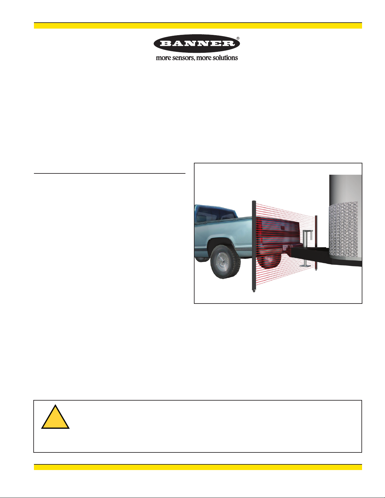
1.0 System Overview
The Banner A-GAGE MINI-ARRAY Two-Piece Measuring Light Screen was
customized for vehicle separation applications. It incorporates the popular
MINI-ARRAY emitter and receiver design and ease of use, while simplifying
installation. This two-piece system does not require a separate controller.
A typical system consists of four components:
• Emitter
• Receiver
• Two interconnecting cables
Models are available in array lengths from 150 to 1220 mm in 150 mm increments
(6" to 4' in 6" increments), plus 1520 mm (5') and 1830 mm (6') lengths. Models
are listed in Section 2.1. Beam spacing is 19.1 mm (3/4"). Sensing range is 0.9 to
15 m (3' to 50').
MINI-ARRAY
Two-Piece Measuring Light Screen
®
Figure 1-1. Typical vehicle separation application
2 P/N 117167 rev. A
Banner Engineering Corp. • Minneapolis, MN U.S.A.
www.bannerengineering.com • Tel: 763.544.3164
Page 3
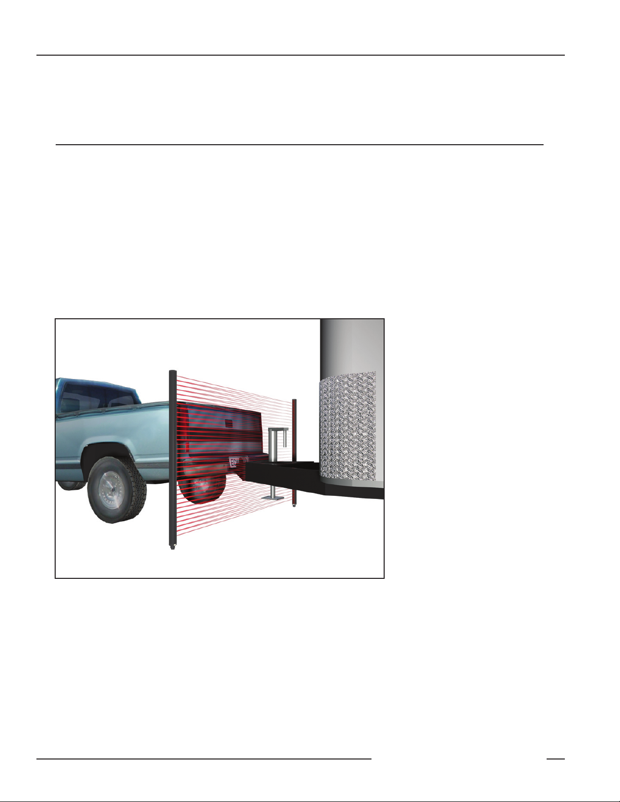
MINI-ARRAY
Emitter
Receiver
Red
Operational
LED
Green Alignment LED
Red Blocked LED
Yellow Marginal
Alignment LED
Two-Piece Measuring Light Screen
®
System Overview
1.1 System Features
Built-in features simplify the operation of the MINI-ARRAY Two-Piece Light Screen
system, which is customized to specifically address the demanding requirements
needed to reliably detect vehicle separation. Large optical lenses provide strong
optical excess gain (needed for demanding outdoor environments).
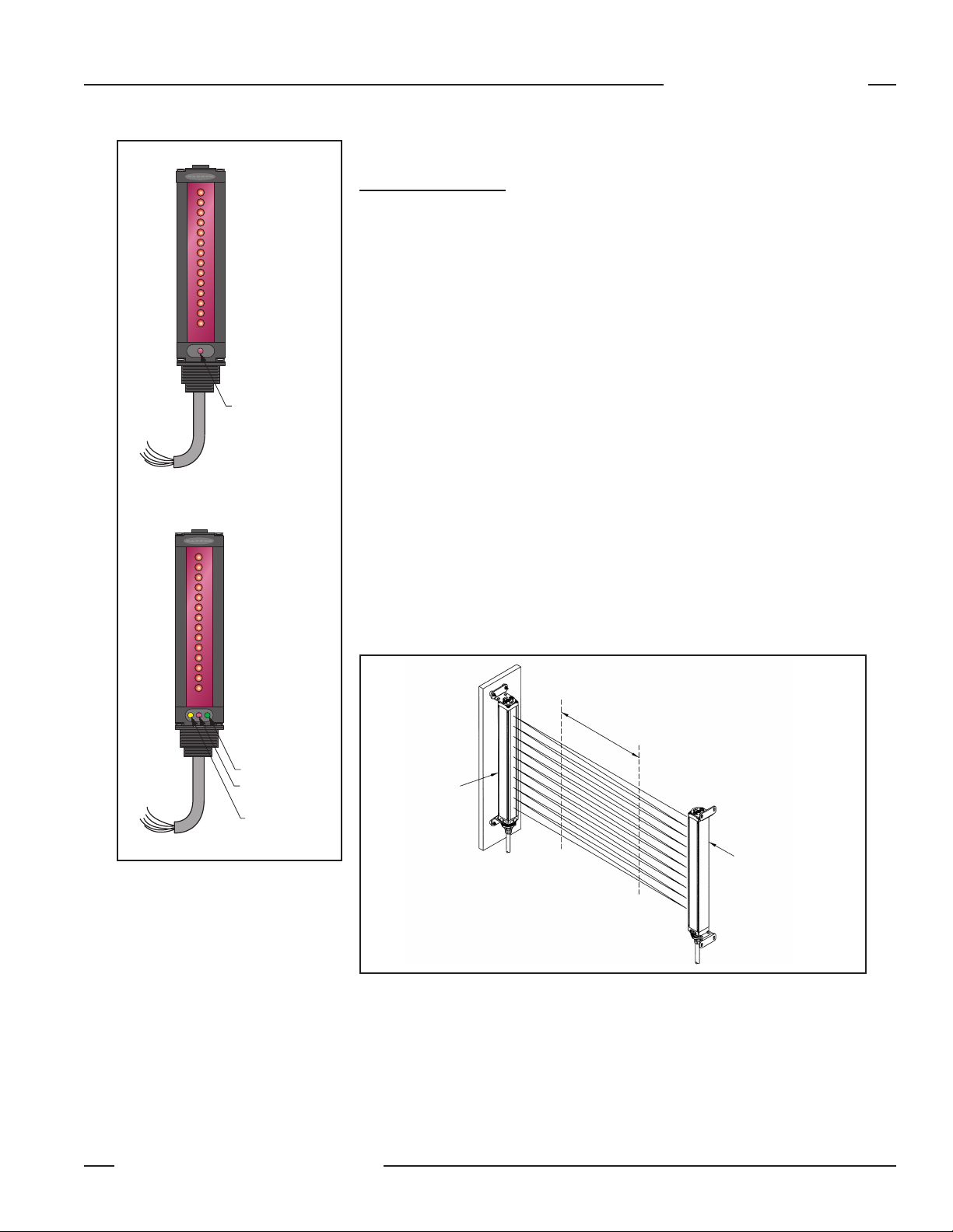
The system is pre-configured for an interlaced optical pattern, which provides
the minimum object detection necessary to detect a trailer hitch. A sensor scan
involves individually enabling each emitter channel twice. In effect, each emitter
channel fires at both its opposing receiver element, and at the one beneath it.
The result is an interlaced optical detection pattern, as shown in Figure 1-3. This
pattern can better detect objects within the middle third of the sensing area.
Along with using the interlaced pattern, the sensor processes the scan data in
a method that is tailored for Vehicle Separation applications: both for initial car
detection and trailer detection (see Sections 1.2 and 1.3). Several important
features have been built into the MINI-ARRAY Two-Piece system:
• Easy-to-understand diagnostic LEDs
Figure 1-2. System features
• 2 discrete outputs
• EIA-485 serial communication
• Self-diagnostics to detect dirty lens, faulty or degraded sensor operation
conditions
Interlaced Scan improves optical
resolution in the middle one-third
of the scanning range.
Emitter
Receiver
Figure 1-3. Interlaced scan
Banner Engineering Corp. • Minneapolis, MN U.S.A.
P/N 117167 rev. A 3
www.bannerengineering.com • Tel: 763.544.3164
Page 4
System Overview
Two-Piece Measuring Light Screen
1.1.2 Easy-to-Understand Diagnostic LEDs
The system provides simple, straightforward indications of sensor performance
(see Figure 1-2). See Section 3.3 for a more detailed guide to troubleshooting
system status using the diagnostic LEDs.
Emitter: 1 Red Diagnostic LED
LED Condition ON Solid OFF Flashing (5x per second) Flashing (1x per second)
MINI-ARRAY
®
Emitter Condition
Sensor is functioning
normally
No power to emitter
Receiver is removed from
the system
Receiver: 3 Diagnostic LEDs (Green, Red, and Yellow)
The combined status of the Green and Red LEDs provides a simple sensor
alignment process. The Yellow LED signals a dirty lens or degraded sensor
condition (see Section 1.4).
LED Condition ON Solid OFF Flashing (2 Hz)
Green
Red
Yellow
Light screen is
unobstructed
Light screen is
obstructed
Dirty lens (whether
light screen is blocked
or clear); will remain
ON until receiver
detects proper light
signal strength
Light screen is
obstructed
Light screen is
unobstructed
Non-functioning emitter
Non-functioning emitter
Light signal of one or more beam(s) is degraded
1.1.3 Two Solid-State Outputs
One or more emitter optical
channel(s) not working
properly
The receiver has two discrete outputs (Output #1 and Output #2). Each output is
independent and can be configured for either NPN or PNP operation. The sensor
is factory-configured for NPN outputs, with Output #1 designated for vehicle
separation detection and Output #2 for sensor “health” status output. These
outputs are rated to 150 mA and are short circuit protected.
1.1.4 EIA-485 Interface
To provide sensor profiling and system status information, the receiver has a serial
EIA-485 interface. Please see Appendix A for further information.
1.1.5 Sensing Scan Time
Sensing scan time is a function of the sensor length and number of beams
interrogated (i.e. steps) per scan of the array. The models table in Section 2.1
provides scan times for the Vehicle Separation scanning application (labeled as
interlaced scanning) for each light screen size. The worst-case response time is
twice the scan time.
4 P/N 117167 rev. A
Banner Engineering Corp. • Minneapolis, MN U.S.A.
www.bannerengineering.com • Tel: 763.544.3164
Page 5

MINI-ARRAY
Two-Piece Measuring Light Screen
®
System Overview
1.1.6 Supplied System Software
The system provides other scanning modes and operation features, which are not
optimized for vehicle separation but are useful for other applications.
These features are easily accessed via a simple-to-use Banner-supplied PC
software program and an appropriate EIA-485 interface (consult a Banner
Engineering representative for more information). The PC software can be run
on any computer running Windows® 98, NT, ME, XP or 2000. The menu-driven
program walks the user through the many scanning and output options. After the
desired options are selected, download the settings to the receiver; the receiver will
store the configuration settings in non-volatile memory.
This software also enables the user to check sensor alignment, obtain sensor
readings, and verify sensor status. The built-in system diagnostics can be used to
assess emitter and receiver hardware errors or dirty lens locations.
1.2 Vehicle Detection Applications (Output #1)
The MINI-ARRAY Two-Piece Light Screen features a superior interlaced (crosshatched) beam pattern. When the light screen is clear (no object is obstructing
the receiver’s view of the emitted beam pattern), the sensor will ignore small
objects while waiting to detect the beginning of a vehicle. Up to 125 mm (5”) of
consecutive light channels must be blocked before a valid object is detected; once
the sensor detects 125 mm or more of consecutive blocked light, Output # 1 will
become active (output ON).
1.3 Trailer Hitch Detection Applications (Output #1)
Once an object is detected (see Section 1.1.1), Output #1 will remain active until
the receiver again detects the entire emitter beam pattern (sensor is clear). The
interlaced scan pattern will detect smaller objects after initially detecting a vehicle,
even if only one beam is obstructed. Once the receiver detects a fully unobstructed
light screen, Output #1 again will become inactive (output OFF).
1.4 System Self-Diagnostics (Output #2)
Advanced electronic and data processing allows the receiver to continually monitor
and evaluate light signal quality and alert the user to light signal degradation or
sensor faults. The sensor can detect marginal alignment, permanently blocked
channels, a faulty emitter element, or a non-functioning emitter.
This receiver was designed to detect system failures and remain operational.
Potential problems include a dirty lens that totally blocks (occludes) the optical
light signal or a light signal failure (caused by either the emitter or receiver).
Although sensor failures are rare, the Two-Piece MINI-ARRAY has been designed
to continue to function while warning the user of fault conditions, minimizing
system down time and providing advance notice that system maintenance or
repairs are required.
Whenever the receiver detects proper operation, Output #2 is active (ON). When
the sensor detects a system problem (either a sensor fault or a degraded signal),
Output #2 is disabled (goes OFF, an alarm condition).
A system problem is acknowledged in three ways:
1. The condition of the diagnostic LEDs,
2. Output #2 will be inactive (OFF), and
3. The condition can be transmitted to the monitoring system, via the EIA-485
interface (see Appendix A, System Status Information: command 0x66).
Banner Engineering Corp. • Minneapolis, MN U.S.A.
P/N 117167 rev. A 5
www.bannerengineering.com • Tel: 763.544.3164
Page 6

System Overview
Two-Piece Measuring Light Screen
1.4.1 Marginal Alignment/Dirty Lens Detection (Output #2)
When the received light signal drops below a predetermined threshold, the receiver
will recognize a “marginal alignment” or “dirty lens” condition. (The dirty lens
threshold is equivalent to three times the minimum light signal necessary for
detection.)
Once this condition is detected, the receiver will signal the user that the lens
surface should be cleaned or re-aligned. The Yellow diagnostic LED will turn ON
until the condition is no longer detected (whether the light screen is blocked or
clear). This advance recognition can be used to initiate a proper maintenance
process.
1.4.2 Fault Detection and Sensor Degradation Operation (Output #2)
The receiver detects an occluded light channel detected when one or two
consecutive light channels remain blocked after eight or more vehicles are
detected. Once a blocked channel is detected (the Yellow diagnostic LED will
flash at 2 hertz), the receiver will note the fault and begin to operate in sensor
degradation mode.
Once the receiver detects a permanently blocked optical channel, it will effectively
ignore the degraded optical channel while continuing to operate. This allows the
sensor to continue working and for many instances, provide reliable service.
MINI-ARRAY
®
Along with ignoring permanently blocked channels, the sensor continuously
monitors sensor performance. Should an optical channel become inoperable (due
to a faulty light channel), the sensor will detect the problem and begin to operate
in the sensor degradation mode. Sensor degradation mode provides the user with
advance notice of a fault while continuing to maintain a functional traffic lane.
Emitter faults: In addition to sensing a permanently blocked channel and a faulty
light channel, the receiver can detect a non-functioning emitter (possibly caused by
a disconnected cable). The receiver’s Green and Red diagnostic LEDs will flash at 2
hertz to signal this emitter condition.
6 P/N 117167 rev. A
Banner Engineering Corp. • Minneapolis, MN U.S.A.
www.bannerengineering.com • Tel: 763.544.3164
Page 7

MINI-ARRAY
75.1 mm
(2.95")
Y
L1
White
Blue
Pink
Gray
Yellow
Green
Brown
Red
M12 x 1
ø 15 mm
(0.6")
44 mm max.
(1.7")
®
Two-Piece Measuring Light Screen
2.0 Specifications
2.1 Emitter and Receiver Models
Specifications
Emitter/Receiver
Models*
MAE616 Emitter
MAR616NX485 Receiver
MAE1216 Emitter
MAR1216NX485 Receiver
MAE1816 Emitter
MAR1816NX485 Receiver
MAE2416Q Emitter
MAR2416NX485 Receiver
MAE3016 Emitter
MAR3016NX485 Receiver
MAE3616 Emitter
MAR3616NX485 Receiver
MAE4216 Emitter
MAR4216NX485 Receiver
MAE4816 Emitter
MAR4816NX485 Receiver
MAE6016 Emitter
MAR6016NX485 Receiver
MAE7216 Emitter
MAR7216NX485 Receiver
* Standard cabled models (2 m/6.5' long) only are listed. For 150 mm (6.5") Euro-style pigtail
QD model, add suffix “Q” to any model (e.g., MAE616Q).
** Worst-case response time is twice the scan time.
†
Scan time for Vehicle Separation scanning configuration.
Sensor Scan Time**
Interlaced
Scan
1.4 ms 0.91 ms
2.5 ms 1.5 ms
3.6 ms 2.0 ms
4.8 ms 2.6 ms
5.9 ms 3.2 ms
7.0 ms 3.7 ms
8.1 ms 4.3 ms
9.2 ms 4.8 ms
11.5 ms 6.0 ms
13.7 ms 7.1 ms
Straight
†
Scan
Array
Length
(Y)
143 mm
(5.62")
295 mm
(11.62")
448 mm
(17.62")
600 mm
(23.62")
752 mm
(29.62")
905 mm
(35.62")
1057 mm
(41.62")
1210 mm
(47.62")
1514 mm
(59.62")
1819 mm
(71.62")
Housing
Length
(L1)
231 mm
(9.1")
384 mm
(15.1")
536 mm
(21.1")
689 mm
(27.1")
841 mm
(33.1")
993 mm
(39.1")
1146 mm
(45.1")
1298 mm
(51.1")
1603 mm
(63.1")
1908 mm
(75.1")
Total
Beams
8
16
24
32
40
48
56
64
80
96
2.2 Euro-Style Quick-Disconnect Cables
Cable: PVC jacket, polyurethane connector body, chrome-plated brass coupling nut
Conductors: 24 AWG high-flex stranded, PVC insulation, gold-plated
Model Length Style Connector Pin Out (female view)
MAQDC-806
MAQDC-815
MAQDC-830
MAQDC-850
MAQDC-875
MAQDC-8100
MAQDC-8125
MAQDC-8150
Banner Engineering Corp. • Minneapolis, MN U.S.A.
P/N 117167 rev. A 7
www.bannerengineering.com • Tel: 763.544.3164
2 m (6.5')
5 m (15')
9 m (30')
15 m (50')
22 m (75')
30 m (100')
38 m (125')
46 m (150')
8-pin
Euro-style
straight
with shield
Page 8

Specifications
2.3 Specifications
MINI-ARRAY
Two-Piece Measuring Light Screen
®
Supply Voltage
and Power
Supply Protection
Circuitry
Discrete Output
Configuration
Serial Data Outputs
Controller
Programming
Emitter/Receiver
Range
Minimum Object
Sensitivity
Sensor Scan Time
Cable Connections
Status Indicators
(see Section 3.3 for
more information)
Environmental
Rating
Construction
Operating
Conditions
Application Notes
16 to 30V dc. Maximum power 12 watts.
Protected against transient voltages and reverse polarity
2 Discrete Outputs: Output 1 and Output 2. Outputs can be configured as either open collector NPN or PNP
transistors. For the vehicle separation application, the outputs are factory configured as NPN outputs.
Discrete Output (either NPN or PNP) ratings: Rated at 30V dc max, 150 mA max load, short circuit protected
OFF-State Leakage Current: <10 µA @ 30V dc
ON-State Saturation Voltage: <1V @ 10 mA, <1.5V @ 150 mA
EIA-485 interface
Baud rate 9600, 19.2 K, 38.4 K
8 data bits, 1 start bit, 1 stop bit, no parity
Via EIA-485 to PC-compatible computer running Windows® 98, NT, ME, XP, 2000 Operating System
Sensors < 1220 mm (4') long: 0.9 to 16.5 m (3' to 55')
Sensors ≥ 1220 mm (4') long: 0.9 to 13.5 m (3' to 45')
NOTE: Maximum range is specified at the point where 3x excess gain remains.
Interlaced Mode: 25.4 mm (1.0")*
Other scanning modes: 38.1 mm (1.5")
*NOTE: Assumes sensing is in middle one-third of scanning range.
See Section 2.1.
NOTE: Worst-case response time is twice the scan time.
Emitter and receiver connections: See Figure 3-6. For QD versions, use cable listed in Section 2.2.
Emitter and receiver cables may not exceed 80 m (250') each.
Emitter
Red LED lights for proper operation
NEMA 4, 13 (IEC IP65)
Aluminum housing with black anodized finish; acrylic lens cover
Temperature: -40° to +70° C (-40° to +158° F)
Max. rel. humidity: 95% (non-condensing)
• The emitter and receiver sync lines (pink and white wires) will be damaged if connected to the power supply.
• The receiver EIA-485 interface (red and green wires) will be damaged if connected to the power supply.
Receiver
Green: sensors aligned (> 3x excess gain)
Yellow: marginal alignment (1x-3x excess gain)
Red: sensors misaligned or beam(s) blocked
8 P/N 117167 rev. A
Banner Engineering Corp. • Minneapolis, MN U.S.A.
www.bannerengineering.com • Tel: 763.544.3164
Page 9

MINI-ARRAY
Y
L1
L2
L3
75.1 mm
(2.95")
With Bracket Flanges “Out” With Bracket Flanges “In”
Two-Piece Measuring Light Screen
®
2.4 Emitter and Receiver Mounting Dimensions
Specifications
Emitter/Receiver
Models
MAE616 Emitter
MAR616NX485 Receiver
MAE1216 Emitter
MAR1216NX485 Receiver
MAE1816 Emitter
MAR1816NX485 Receiver
MAE2416 Emitter
MAR2416NX485 Receiver
MAE3016 Emitter
MAR3016NX485 Receiver
MAE3616 Emitter
MAR3616NX485 Receiver
MAE4216 Emitter
MAR4216NX485 Receiver
MAE4816 Emitter
MAR4816NX485 Receiver
MAE6016 Emitter
MAR6016NX485 Receiver
MAE7216 Emitter
MAR7216NX485 Receiver
Housing
Length
(L1)
231 mm (9.1") 262 mm (10.3") 205 mm (8.1")
384 mm (15.1") 414 mm (16.3") 357 mm (14.1")
536 mm (21.1") 567 mm (22.3") 510 mm (20.1")
689 mm (27.1") 719 mm (28.3") 662 mm (26.1")
841 mm (33.1") 871 mm (34.3") 815 mm (32.1")
993 mm (39.1") 1024 mm (40.3") 967 mm (38.1")
1146 mm (45.1") 1176 mm (46.3") 1119 mm (44.1")
1298 mm (51.1") 1329 mm (52.3") 1272 mm (50.1")
1603 mm (63.1") 1633 mm (64.3") 1577 mm (62.1")
1908 mm (75.1") 1938 mm (76.3") 1881 mm (74.1")
Distance Between Bracket Holes
L2 L3
Figure 2-1. Emitter and receiver mounting dimensions and defined area location
Banner Engineering Corp. • Minneapolis, MN U.S.A.
P/N 117167 rev. A 9
www.bannerengineering.com • Tel: 763.544.3164
Page 10

Emitter
or
Receiver
Mounting
Mounting
Bracket
Surface
M4
Nut (4)
Washer (2)
with Compression
Slotted Hex Head
M4 x 10 mm
Bracket
Mounting
Nut
Washer
M4 x 14 mm
Screw with Flat
Washer
Compression
Washer (4)
Torque to
12 in. lbs.
(1.3 N-m)
Installation and Alignment
MINI-ARRAY
Two-Piece Measuring Light Screen
®
3.0 Installation and Alignment
3.1 Emitter and Receiver Mounting
Banner MINI-ARRAY emitters and receivers are small, lightweight, and easy to mount; the mounting brackets (supplied) allow
±30 degrees rotation.
From a common point of reference, make measurements to position the emitter and receiver in the same plane with their
midpoints directly opposite each other. Mount the emitter and receiver brackets using the M4 x 0.7 x 14 mm bolts and
associated mounting hardware (all supplied). See Figure 3-1.
Although the internal circuitry of the emitter and receiver can withstand heavy impulse forces, vibration isolators can be used
instead of the M4 bolts to dampen impulse forces and prevent possible damage from resonant vibration of the emitter or
receiver assembly. Two different Anti-Vibration Mounting Kits are available from Banner as accessories.
P/N 48955 consists of 4 antivibration mounts (M4 x 0.7 x 9.5
mm) and 8 M4 Keps nuts. These
mounts are made from BUNA-N
rubber and are more resistant to
chemicals and oils.
P/N 12847 consists of 4 antivibration mounts (M4 x 0.7 x 9.5
mm) and 8 M4 Keps nuts. These
mounts are made from natural
rubber, which are less chemically
resistant than the 48955 mounts, but
have a greater sheer force spec at
higher temperature.
Figure 3-1. MINI-ARRAY emitter and receiver mounting hardware
10 P/N 117167 rev. A
Banner Engineering Corp. • Minneapolis, MN U.S.A.
www.bannerengineering.com • Tel: 763.544.3164
Page 11

MINI-ARRAY
Min. R.
34.8 mm
(1.37")
Slots have clearance
for M4 bolts (supplied)
and allow ± 30° rotation
11.9 mm
(0.47")
24.6 mm
(0.97")
57.2 mm
(2.25")
44.5 mm
(1.75")
R 6.4 mm
(0.97")
10.2 mm (2)
(0.40")
Full R (4)
38.1 mm
(1.5")
4.8 mm (2)
(0.19")
3.8 mm
(0.15")
6.4 mm
(0.25")
QD End Non-QD End
ø 30.5 mm
(ø 1.2")
ø 13.2 mm
(ø 0.52")
ø 6.8 mm (2)
(ø 0.27")
3.0 mm
(0.12")
53.8 mm
(2.12")
Tr im foil shield flush
with cable
Uninsulated
drain wire
13 mm (0.5") radius minimum bend
®
Two-Piece Measuring Light Screen
Installation and Alignment
Mount the emitter and receiver in their mounting brackets (see Figure 3-1), and
position the red lenses of the two units directly facing each other. The connector
ends of both sensors must point in the same direction. Measure from one or more
reference planes (i.e., the floor) to the same points on the emitter and receiver to
verify their mechanical alignment. If the sensors are positioned exactly vertical
or exactly horizontal, a carpenter’s level may be useful for checking alignment.
Extending a straight-edge or a string between the sensors may help with
positioning. Also check by eye for line-of-sight alignment. Make any necessary final
mechanical adjustments, and hand-tighten the bracket hardware.
Figure 3-2. Cable clearances
The “drain wire” is the uninsulated
stranded wire which runs between the
cable jacket and the foil shield. Remove
the foil shield at the point where the wires
exit the cable.
Figure 3-3. Emitter/receiver cable
preparation
Figure 3-4. MINI-ARRAY emitter and receiver mounting bracket dimensions
Connect the shielded cables to the emitter and receiver, and route them to the
terminal location. Follow the local wiring code for low-voltage dc control cables.
The same cable type is used for both emitter and receiver (two cables required per
system). Cut the cables to length after making sure they are routed properly.
P/N 117167 rev. A 11
Banner Engineering Corp. • Minneapolis, MN U.S.A.
www.bannerengineering.com • Tel: 763.544.3164
Page 12

L
LÕ
«
Ü
}Þ
Þi
À`
À`
}
}
L>Ài
L
LÕ
«
Ü
}Þ
Þi
³
q
£ÈÎä6Ê`V
*°-°Ê6ʳ
*°-°Ê6Êq
-9 ʳ
-9 Êq
"1/£
"1/ÓÉ,
Ê{nxʳ
Ê{nxÊq
- -
*°-°Ê6³
*°-°Ê6q
-9 ʳ
-9 Êq
,iViÛiÀ ÌÌiÀ
>`Ê£
>`ÊÓ
Ê*ÜiÀ
-Õ««Þ
ÌÊiÝÌiÀ>
{nx
`iÛViÊÌiÀ>
ViVÌ
Installation and Alignment
3.2 Emitter and Receiver Hookups
Connect the emitter and receiver cables as
shown in Figure 3-6.
Receiver Output 1: (OUT1) is an opencollector NPN transistor switch rated at
30V dc max., 150 mA max. It is protected
against overload and short circuits.
Receiver Alarm: (ALARM) is an opencollector NPN transistor switch rated at
30V dc max., 150 mA max. It is protected
against overload and short circuits.
Both outputs are current sinking.
3.3 Diagnostic LED Indicators
The emitter has a single Red status LED.
The receiver’s three LEDs (Green, Yellow,
and Red) are used in combination to
diagnose system status.
Figure 3-5. A-GAGE MINI-ARRAY Two-Piece Measuring Light Screen hookup diagram
MINI-ARRAY
Two-Piece Measuring Light Screen
®
Receiver LED Condition
System Status Possible Action
Green Yellow Red
ON OFF OFF Emitter/receiver pair aligned • None
ON ON OFF Emitter/receiver pair aligned with dirty lens
• Clean lenses
• Align emitter and receiver
OFF OFF ON Emitter/receiver pair blocked • None
OFF ON ON Emitter/receiver pair blocked with dirty lens
• Clean lenses
• Align emitter and receiver
ON ON ON Receiver error • Replace receiver
ON
OFF
Flashing
@ 2 Hz
Flashing
@ 2 Hz
Flashing
@ 2 Hz
OFF
OFF Degraded mode; emitter/receiver pair aligned
ON Degraded mode; emitter/receiver pair blocked
Flashing
@ 2 Hz
Emitter is not functioning • Connect emitter
• Clean lenses
• Align emitter and receiver*
• Clean lenses
• Align emitter and receiver*
Emitter LED Condition Emitter Status Possible Action
Red ON Emitter operating properly • None
Red Flashing @ 1 Hz Emitter is degraded • Replace emitter
Red Flashing @ 5 Hz Emitter has power, but receiver is not hooked up • Connect or replace receiver
* If after cleaning the emitter and receiver lenses, the emitter diagnostic is solid Red, consider replacing the receiver.
3.4 Optical Alignment
After connecting the cables per Figure 3-5, apply 16-30V dc power to the sensor.
Rotate the emitter and/or receiver as necessary to align them. When aligned, the
receiver Green LED is ON. Align the emitter and receiver until the receiver’s Green
LED is ON and the Yellow and Red LED are OFF.
12 P/N 117167 rev. A
Banner Engineering Corp. • Minneapolis, MN U.S.A.
www.bannerengineering.com • Tel: 763.544.3164
Page 13

MINI-ARRAY
Two-Piece Measuring Light Screen
Command
Value
(Hexadecimal)
0x53
0x64
0x66
0x67
Table A-1.
®
Command
Description
Request Sensor to
Scan
Request Sensor
to Transmit Each
Optical Channel
State
(0-clear, 1-blocked)
Request Sensor to
Transmit System
Status Information
Request Sensor to
Transmit One or Two
Measurement Values
Appendix A
Appendix A. Serial Communication
Appendix A describes the serial communication data format and commands
that are available to serially communicate over the EIA-485 interface. The
serial commands can be used to initiate scanning, request sensor light channel
information, request system status, and request one or two sensor measurements.
The serial communication data format utilized by the sensor is described and
related to the sensor commands; examples follow.
Serial Communication Data Format
The serial communication utilizes a standard universal asynchronous receiver/
transmitter architecture. The sensor baud rate can be 9600, 19200, or 38400.
The data will have one start bit, one stop bit, no parity, eight data bits and is
transmitted least significant bit first. The serial communication string format will
consist of a start-of-header byte, a sensor-identification byte, a command byte, a
count of the data bytes, the data bytes, and a two-byte check sum.
All serial communication will follow this data format. The start-of-header byte
will always have hexadecimal value 0xF4 (244 decimal). The sensor identification
byte can have hexadecimal values ranging from 0x41 through 0x5A (65 through 90
decimal). The command bytes used for the sensor are listed in Table A-1.
The count of the data bytes defines the number of data bytes that will be
transmitted for the particular command. For instance, if four data bytes are
transmitted, then the value for the number of data bytes will equal four. The actual
data bytes follow the byte representing the number of data bytes. The check sum
is a two-byte value that is calculated by summing the previous bytes in the string.
Once the sum is known, then a ones complement of the sum is calculated and
used as the string check sum value. Examples will be given in the description of
each command.
Request Sensor to Scan Command (Command 0x53)
This command will be used when the sensor is configured for host scanning. This
command is useful for instances where multiple sensors are present and sensor
cross talk is an issue. Assuming the sensor ID is 0x41, the command string would
be as follows:
Transmit string to sensor: 0xF4, 0x41, 0x53, 0x00, 0x77, 0xFE
Receive string from sensor: 0xF4, 0x41, 0x53, 0x01, 0x06, 0x70, 0xFE
This receive string would be interpreted as follows:
0xF4 is the start-of-header byte
0x41 is the sensor-identification byte
0x53 is the command requesting the sensor scan initiation
0x01 is the number of data bytes
0x06 is the valid response stating that the sensor initiated a scan
The last two bytes are the check sum in low-byte, high-byte order and calculated
as follows:
0xF4 + 0x41 + 0x53 + 0x01 + 0x06 = 0x18F.
The ones complement of 0x18F = 0xFE70.
Hence the low-byte, high-byte order would be 0x70, 0xFE.
Banner Engineering Corp. • Minneapolis, MN U.S.A.
P/N 117167 rev. A 13
www.bannerengineering.com • Tel: 763.544.3164
Page 14

Appendix A
Request Sensor to Transmit all Receiver Channel State (Command 0x64)
This command requests the sensor to provide the state of each optical channel.
The two states for each optical channel are clear (value =0) and blocked (value
=1). Eight optical channels of information are transmitted in each data byte. The
first data byte contains the information for the eight optical channels located
closest to the sensor cable end cap. The following data bytes will contain
information for eight successive optical channel sections. For a data byte, each bit
of the data byte is directly related to the status of an individual optical channel. For
example, if the first eight optical channels have the following states:
MINI-ARRAY
Two-Piece Measuring Light Screen
®
Optical
Channel
Position
1 blocked 1 5 clear 0
2 clear 0 6 blocked 1
3 blocked 1 7 clear 0
4 blocked 1 8 clear 0
Status
Binary
Value
Optical
Channel
Position
Status Binary Value
Then the data byte would be 0x2D. If the array has 32 optical channels, then there
would be four data bytes representing the status of all 32 optical channels. Assume
that the sensor ID is 0x41 and the following serial transmission occurs:
Transmit string to sensor: 0xF4, 0x41, 0x64, 0x00, 0x66, 0xFE
Receive string from sensor: 0xF4, 0x41, 0x64, 0x04, 0x2D, 0x03, 0xC0, 0x81,
0xF1, 0xFC
This receive string would be interpreted as follows:
0xF4 is the start-of-header byte
0x41 is the sensor-identification byte
0x64 is the command requesting the sensor optical channel information
0x04 is the number of data bytes
0x2D optical channels 1, 3, 4, 6 are blocked; optical channels 2, 5, 7, 8 are
clear
0x03 optical channels 9 and 10 are blocked; optical channels 11-16 are clear
0xC0 optical channels 17-22 are clear; optical channels 23 and 24 are blocked
0x81 optical channels 25 and 32 are blocked; optical channels 26-31 are clear
The last two bytes are the check sum in low-byte, high-byte order
Request Sensor to Transmit System Status Information (Command 0x66)
This command will be used to extract information about the sensor. The
information that can be received includes the following six data bytes:
Number of Emitter Channels
First Emitter Failed Channel
Number of Receiver Channels
First Bad Receiver Channel
State
0 – System is working properly
1 – System detects weak alignment
2 – System detects dirty lens
3 – System detects degraded emitter (faulty emitter element)
4 – System detects emitter is not functioning
Degraded Channel
14 P/N 117167 rev. A
Banner Engineering Corp. • Minneapolis, MN U.S.A.
www.bannerengineering.com • Tel: 763.544.3164
Page 15

MINI-ARRAY
Two-Piece Measuring Light Screen
®
Appendix A
Assume that the system has 48 channels and the system detects weak alignment.
The transmit and receiver strings would be as follows:
Transmit string to sensor: 0xF4, 0x41, 0x66, 0x00, 0x64, 0xFE
Receive string from sensor: 0xF4, 0x41, 0x66, 0x06, 0x30, 0x00, 0x30, 0x00,
0x01, 0x00, 0xFD, 0xFD
This receive string would be interpreted as follows:
0xF4 is the start-of-header byte
0x41 is the sensor-identification byte
0x66 is the command requesting the sensor status information
0x06 is the number of data bytes
0x30 there are 48 emitter channels
0x00 all emitter channels are OK
0x30 there are 48 receiver channels (that’s good, because the emitter has 48
channels also!)
0x00 all receiver channels are OK
0x01 the system detects weak alignment
0x00 there are no degraded channels
The last two bytes are the check sum in low-byte, high-byte order.
Request Sensor to Transmit One or Two Measurement Values (Command 0x67)
This command requests the sensor to transmit the previous scan’s measurement
values (one or two measurement values). The command will transmit either two or
four bytes (as specified by the sensor configuration). Assume that the sensor ID
is 0x41 and the sensor is configured to transmit the First Beam Blocked and Total
Beams Blocked information. Also assume that the twentieth light channel happens
to be the first beam blocked and a total of 15 light channels are blocked.
Transmit string to sensor: 0xF4, 0x41, 0x67, 0x00, 0x63, 0xFE
Receive string from sensor: 0xF4, 0x41, 0x67, 0x04, 0x14, 0x00, 0x0F, 0x00,
0x3C, 0xFE
This receive string would be interpreted as follows:
0xF4 is the start-of-header byte
0x41 is the sensor-identification byte
0x67 is the command requesting the sensor measurement information
0x04 is the number of data bytes
0x14, 0x00 is the low-byte, high-byte integer value for the first beam
blocked = 20
0x0f, 0x00 is the low-byte, high-byte integer value for the total beams
blocked=15
The last two bytes are the check sum in low-byte, high-byte order. The check sum
is calculated as follows:
0xF4 + 0x41 + 0x67 + 0x04 + 0x14 + 0x00 + 0x0F + 0x00 = 0x1C3.
The ones complement of 0x1C3 = 0xFE3C.
Hence the low-byte, high-byte order would be 0x3C, 0xFE.
Banner Engineering Corp. • Minneapolis, MN U.S.A.
P/N 117167 rev. A 15
www.bannerengineering.com • Tel: 763.544.3164
Page 16

WARRANTY: Banner Engineering Corp. warrants its products to be free from defects for one year. Banner Engineering Corp. will
repair or replace, free of charge, any product of its manufacture found to be defective at the time it is returned to the factory
during the warranty period. This warranty does not cover damage or liability for the improper application of Banner products. This
warranty is in lieu of any other warranty either expressed or implied.
P/N 117167 rev. A
Banner Engineering Corp., 9714 Tenth Ave. No., Minneapolis, MN USA 55441 • Phone: 763.544.3164 • www.bannerengineering.com • Email: sensors@bannerengineering.com
 Loading...