

Banner ABR7109-RSE2, ABR7109-MSE2, ABR7112-RSE2, ABR7116-RSE2, ABR7106-RSE2, ABR7106-MSE2, ABR71L9-RSE2, ABR71L9-MSE2, ABR7109-MSE2, ABR7109-RSE2, ABR7116-RSE2, ABR7106-RSE2 Instruction Manual
...Page 1

ABR 7000 Series Barcode Reader
207634
Instruction Manual
Original Instructions
207634 Rev. A
28 January 2019
©
Banner Engineering Corp. All rights reserved
Page 2

ABR 7000 Series Barcode Reader
Contents
1 Product Description
1.1 Models ............................................................................................................................................................................................ 4
1.2 Laser Description and Safety Information ...................................................................................................................................... 4
1.3 Features .......................................................................................................................................................................................... 5
1.3.1 Indicators .................................................................................................................................................................................6
1.3.2 Diagnostic Indication ...............................................................................................................................................................6
1.3.3 Button ......................................................................................................................................................................................6
........................................................................................................................................................4
2 Specifications and Requirements ...................................................................................................................................7
2.1 Specifications—Reader .................................................................................................................................................................. 7
2.2
Specifications—Software ............................................................................................................................................................... 8
2.3 PC Requirements—Barcode Manager ........................................................................................................................................... 8
2.4 Dimensions ...................................................................................................................................................................................... 8
3 Installation Instructions .................................................................................................................................................10
3.1 Handling ........................................................................................................................................................................................10
3.2 Mount the Reader ......................................................................................................................................................................... 10
3.3 Position the Reader ...................................................................................................................................................................... 11
3.4 Focus Lock Label—Optional ........................................................................................................................................................ 12
3.5 Typical Layouts .............................................................................................................................................................................12
3.5.1 Ethernet Connection ............................................................................................................................................................. 12
3.5.2 Serial Connection .................................................................................................................................................................. 13
3.5.3 Pass-Through ........................................................................................................................................................................13
3.5.4 ID-NET Multidata Network (Pass-Through) ...........................................................................................................................14
3.5.5 ID-NET Synchronized Network ............................................................................................................................................. 15
3.6 Connector Descriptions ................................................................................................................................................................. 16
3.6.1 Power, Communications, and I/O Connector ....................................................................................................................... 16
3.6.2 Inputs ......................................................................................................................................................................................18
3.6.3 Outputs ...................................................................................................................................................................................18
3.6.4 Wiring .................................................................................................................................................................................... 19
3.6.5 Ethernet Connector ............................................................................................................................................................... 20
3.6.6 Ethernet Interface ..................................................................................................................................................................21
3.7 TCNM-ACBB1 Electrical Connections ......................................................................................................................................... 21
3.7.1 Power Supply ........................................................................................................................................................................ 22
3.7.2 Main Serial Interface ..............................................................................................................................................................22
3.7.3 User Interface—Serial Host ...................................................................................................................................................23
3.7.4 ID-NET Interface ....................................................................................................................................................................24
3.7.5 Auxiliary RS232 Interface ...................................................................................................................................................... 28
3.7.6 Inputs .....................................................................................................................................................................................29
3.7.7 Outputs ..................................................................................................................................................................................33
4 Smart Teach Interface .................................................................................................................................................. 36
4.1 Test Mode .....................................................................................................................................................................................36
4.2 Aim—Manual Focus Models ..........................................................................................................................................................37
4.3 Aim and Autofocus the Reader—Liquid Lens Autofocus Models ................................................................................................ 37
4.4 Setup .............................................................................................................................................................................................38
4.5 Learn .............................................................................................................................................................................................38
5 Getting Started ............................................................................................................................................................. 39
5.1 Install Barcode Manager ...............................................................................................................................................................39
5.2 Ethernet Device Discovery ............................................................................................................................................................39
5.3 Serial Device Discovery ................................................................................................................................................................ 41
6 Device Configuration
6.1 Automatic Setup ........................................................................................................................................................................... 42
6.2 Advanced Setup for Liquid Lens Autofocus Models .................................................................................................................... 43
6.3 Advanced Setup for Manual Adjustable Focus Models ................................................................................................................ 46
6.4 Reading Phase ..............................................................................................................................................................................50
6.5 Good Read Setup ......................................................................................................................................................................... 51
6.6 Data Formatting ............................................................................................................................................................................ 52
6.7 Output Setup ................................................................................................................................................................................ 54
6.8 Fine-Tuning Examples ................................................................................................................................................................... 54
6.8.1 Under-Exposure .................................................................................................................................................................... 54
6.8.2 Over-Exposure ...................................................................................................................................................................... 55
6.8.3 Code Moving Out of the FOV ................................................................................................................................................56
.................................................................................................................................................... 42
7 Advanced Reader Configuration .................................................................................................................................. 58
7.1 Host Mode Programming
............................................................................................................................................................. 58
8 Industrial Ethernet Overview .........................................................................................................................................59
Page 3

ABR 7000 Series Barcode Reader
8.1 Industrial Ethernet Setup in Barcode Manager .............................................................................................................................59
8.1.1 Set the Industrial Ethernet Protocol (EtherNet/IP, Modbus/TCP)
8.1.2 Industrial Ethernet Reading Phase Control ........................................................................................................................... 59
8.1.3 Industrial Ethernet Reading Phase Acquisition Control ........................................................................................................ 61
8.1.4 Industrial Ethernet Digital Output Control ............................................................................................................................. 61
8.1.5 Digital Input Echo to Industrial Ethernet ................................................................................................................................62
8.1.6 Transmitting Output Data Messages Using Industrial Ethernet ............................................................................................63
8.2 EtherNet/IP ................................................................................................................................................................................... 64
8.2.1 ABR Assembly Object Descriptions ......................................................................................................................................64
8.2.2 Configuring the ABR for Ethernet/IP in Barcode Manager ....................................................................................................67
8.2.3 ABR Series EDS File Installation in Studio 5000 Logix Designer Software ...........................................................................68
8.2.4 ABR Series Manual Installation in Studio 5000 Logix Designer Software ............................................................................ 73
8.2.5 ABR Series AOI Installation in Logix Designer Software .......................................................................................................74
8.2.6 AOI Data Description .............................................................................................................................................................77
8.3 Modbus/TCP .................................................................................................................................................................................78
8.3.1 ABR Output Message Data ................................................................................................................................................... 79
8.3.2 Configure the ABR for Modbus/TCP in Barcode Manager ................................................................................................... 79
9 Reading Features
9.1 FOV Calculation ............................................................................................................................................................................ 81
9.2 Global FOV Diagrams ................................................................................................................................................................... 82
9.2.1 Manual Focus Models 6 mm Lens ......................................................................................................................................... 82
9.2.2 Liquid Lens Autofocus Models 9 mm Lens ............................................................................................................................83
9.2.3 Manual Focus Models 9 mm Lens ......................................................................................................................................... 84
9.2.4 Manual Focus Models 12 mm Lens ....................................................................................................................................... 85
9.2.5 Manual Focus Models 16 mm Lens ....................................................................................................................................... 86
9.3 Reading Diagrams ........................................................................................................................................................................ 87
9.3.1 ABR7106-xxE2 (6 mm models) 1D Codes ............................................................................................................................ 88
9.3.2 ABR7106-xxE2 (6 mm models) 2D Codes ............................................................................................................................. 94
9.3.3 ABR7109-xxE2 (9 mm models, manual focus) 1D Codes ......................................................................................................97
9.3.4 ABR7109-xxE2 (9 mm models, manual focus) 2D Codes ....................................................................................................100
9.3.5 ABR7112-RSE2 (12 mm models) 1D Codes ........................................................................................................................ 103
9.3.6 ABR7112-RSE2 (12 mm models) 2D Codes ........................................................................................................................ 107
9.3.7 ABR7116-RSE2 (16 mm models) 1D Codes ........................................................................................................................ 111
9.3.8 ABR7116-RSE2 (16 mm models) 2D Codes ........................................................................................................................ 115
9.4 Maximum Line Speed and Exposure Calculations .....................................................................................................................117
......................................................................................................................................................... 81
.......................................................................................... 59
10 PPI (Pixels Per Inch) Setup Chart ............................................................................................................................. 120
11 Application Examples ...............................................................................................................................................122
11.1 Document Handling .................................................................................................................................................................. 122
11.2 Deformed or Overprinted Code Reading ..................................................................................................................................122
11.3 Direct Part Marking ....................................................................................................................................................................122
11.4 Ink-Jet Printing Technology ......................................................................................................................................................123
11.5 Laser Marking/Etching Technology .......................................................................................................................................... 123
12 Troubleshooting ........................................................................................................................................................125
13 Lighting System Notes ............................................................................................................................................. 127
13.1 Lighting Systems for Direct Part Marking .................................................................................................................................127
13.1.1 Lighting Systems for DPM Overview .................................................................................................................................127
13.1.2 Internal DPM Illuminators .................................................................................................................................................. 127
13.1.3 Lighting Systems for DPM Selection Criteria ....................................................................................................................127
13.2 ABR 7000 Recommended Illuminators .....................................................................................................................................131
13.2.1 Red Illuminator .................................................................................................................................................................. 132
13.2.2 Multicolored DPM Illuminator ............................................................................................................................................132
13.2.3 ABR 7000 Applications ..................................................................................................................................................... 134
14 Accessories ............................................................................................................................................................... 137
14.1 Brackets ....................................................................................................................................................................................137
14.2 Cordsets .................................................................................................................................................................................... 137
14.3 Trigger Kit ................................................................................................................................................................................. 138
14.4 Connection Boxes and Power Supply Boxes ...........................................................................................................................139
15 Product Support and Maintenance .......................................................................................................................... 140
15.1 Repairs ......................................................................................................................................................................................140
15.2 Maintenance ............................................................................................................................................................................. 140
15.2.1 Clean the Reader ...............................................................................................................................................................140
15.2.2 Update the Software and Firmware ................................................................................................................................... 140
15.2.3 Update the Firmware .........................................................................................................................................................140
15.3 Reset the Reader to the Factory Default Environment (Optional) .............................................................................................141
15.4 Contact Us .................................................................................................................................................................................141
15.5 Banner Engineering Corp. Limited Warranty ............................................................................................................................ 143
16 Glossary ....................................................................................................................................................................144
Page 4

ABR 7000 Series Barcode Reader
1 Product Description
Imager-based barcode reader with superior decoding capability and a powerful array of lens and lighting options
WARNING: Not To Be Used for Personnel Protection
Never use this device as a sensing device for personnel protection. Doing so could lead to serious injury
or death. This device does not include the self-checking redundant circuitry necessary to allow its use in
personnel safety applications. A sensor failure or malfunction can cause either an energized or deenergized sensor output condition.
1.1 Models
• Powerful decoding capability to read even
difficult 1D and 2D codes
• Superior ability to read DPM and low contrast codes
• Industrial IP67 metal housing for factory environments
• Autofocus or manual focus models available for ease of setup and
configuration
• Quick
configuration with push buttons or software interface
• Ethernet and serial communications for connection to the factory floor
• Powerful integrated LED lighting and easy focus adjustment in one
package for maximum application flexibility
• Green "good read" and red "no read" feedback spotlights and beeper for
easy monitoring
•
Easy, multi-head system connection to multiply barcode reading power
• Embedded webserver interface for monitoring images and statistics over
any network
Table 1: ABR 7000 Models
Model Resolution Lens Lighting Options Communications Codes
ABR7109-RSE2
ABR7109-MSE2 9 mm, manual focus Multicolored DPM
ABR7112-RSE2 12 mm, manual focus Red
ABR7116-RSE2 16 mm, manual focus Red
ABR7106-RSE2 6 mm, manual focus Red
ABR7106-MSE2 6 mm, manual focus Multicolored DPM
ABR71L9-RSE2
ABR71L9-MSE2
1.3 MP
(1280x1024
pixels)
9 mm, manual focus Red
9 mm, Liquid Lens
Autofocus
9 mm, Liquid Lens
Autofocus
Red
Multicolored DPM
2
Standard Serial/Ethernet 1D and 2D
2
2
1.2 Laser Description and Safety Information
The ABR 7000 internal illuminators contain two aiming Laser LEDs used to position the reader. Disconnect the power
supply when opening the device during maintenance or installation to avoid exposure to hazardous laser light. The laser
beam can be switched on or off through a software command.
This product conforms to the applicable requirements of IEC 60825-1 and complies with 21 CFR 1040.10 except for
deviations pursuant to Laser Notice N° 50, date June 24, 2007. This product is classified as a Class 2 laser product
according to IEC 60825-1 regulations.
2
Multicolored DPM models have red and blue lights for optimized reading of DPM codes.
4 www.bannerengineering.com - Tel: + 1 888 373 6767
Page 5

R
C US
Complies with 21 CFR 1040. 10
except for deviations pursuant
to Laser Notice N°50.
date June 24, 2007
LASER LIGHT - DO NOT ST ARE INTO BEAM
CLAS S 2 LASER PRODUCT
MAX .OUTPUT RADIA TION 1 mW
EMIT TED W AVE LENG TH 630 ~ 680 nm
IEC 60825-1: 2007
www.bannerengineering.com
ABR Series
AVOID EXPOSURE LASER LIGHT
IS EMITTED FROM THIS APERTURE
1
2
3
4
5
6
8
10
9
11
13
12
7
1
2
3
4
5
6
8
10
11
13
12
7
ABR 7000 Series Barcode Reader
CAUTION: Use of controls or adjustments or performance of procedures other than those
specified
herein may result in hazardous radiation exposure. Do not attempt to disassemble this sensor for
repair. A defective unit must be returned to the manufacturer.
For Safe Laser Use - Class 2 Lasers
Do not stare at the laser.
•
• Do not point the laser at a person’s eye.
• Mount open laser beam paths either above or below eye level, where
practical.
• Terminate the beam emitted by the laser product at the end of its useful
path.
Reference IEC 60825-1:2007, Section 8.2.
CAUTION: Never stare directly into the sensor lens. Laser
light can damage your eyes. Avoid placing any mirror-like
object in the beam. Never use a mirror as a retroreflective
target.
Class 2 Lasers
Class 2 lasers are lasers that emit visible radiation in the wavelength range from
400 nm to 700 nm, where eye protection is normally afforded by aversion
responses, including the blink reflex. This reaction may be expected to provide
adequate protection under reasonably foreseeable conditions of operation,
including the use of optical instruments for intrabeam viewing.
Class 2 Laser Safety Notes
Low-power lasers are, by definition, incapable of causing eye injury within the
duration of a blink (aversion response) of 0.25 seconds. They also must emit only
visible wavelengths (400 to 700 nm). Therefore, an ocular hazard may exist only if
individuals overcome their natural aversion to bright light and stare directly into
the laser beam.
Laser wavelength: 630-680 nm Output: 1 mW Pulse Duration: variable
1.3 Features
Figure 1. Models with Manual Adjustable Focus
www.bannerengineering.com - Tel: + 1 888 373 6767 5
1. Smart Teach Interface
2. Button
3. Good Read LED (green)
4. Internal Illuminator
5. Aiming System Laser
Pointers
6. Lens
7. No Read LED (red)
8. Lens Cover
9. Focus Adjustment Screw
10. Power - Serial - I/O
Figure 2. Models with Liquid Lens Autofocus
Connector
11. Ethernet Connector
12. Power ON LED
13. Ethernet Connection LED
Page 6

3
4
5
6
7
1
2
ABR 7000 Series Barcode Reader
1.3.1 Indicators
Indicator Color Description
1 Power Blue Indicates that the reader is connected to the power
2 Ethernet
Connection
3 STATUS Red No read result
4 COM/Test Amber Active result output transmission on the Main serial
Figure 3. Indicators—Back and Top of
During the reader startup, all of the LEDs turn on for one second.
Smart Teach Interface
See
Device
on page 36 for the colors and meanings of the five LEDs when the reader is in Smart Teach mode.
5 TRIGGER/Aim Amber Reading in progress. Do not trigger a new reading
6 GOOD/Setup Green Reading successful
7 READY/Learn Green Ready
Amber Indicates connection to the Ethernet network
supply
port
attempt until the current attempt finishes
1.3.2 Diagnostic Indication
The Status and Ready LEDs blink simultaneously to signal the presence of an error.
Diagnostic message transmission on interfaces can be enabled to provide details
about specific error conditions. See the Diagnostic Error Conditions chart in the
Figure 4. Diagnostic Indicators
Diagnostic page of Barcode Manager.
1.3.3 Button
Use the button for the Smart Teach interface for quick installation without using a PC. The button can be disabled or reconfigured to perform additional functions from Barcode Manager.
See
Smart Teach Interface
on page 36.
6 www.bannerengineering.com - Tel: + 1 888 373 6767
Page 7

ABR 7000 Series Barcode Reader
Specifications and Requirements
2
2.1 Specifications—Reader
Supply Voltage
10 V dc to 30 V dc
Consumption
0.7 A to 0.2 A maximum
Communication Interface
Main RS232 or RS422 full duplex: 2400 bit/s to 115200 bit/s
Auxiliary - RS232: 2400 to 115200 bit/s
Ethernet3: 10/100 Mbit/s
Inputs
Input 1 (External Trigger) and Input 2 opto-isolated and polarity
insensitive
Maximum voltage: 30 V dc
Maximum input current: 10 mA
Outputs
3 NPN/PNP/Push-Pull software selectable, reverse polarity and short
circuit protected outputs available (2 Opto-isolated outputs instead if
using TCNM-ACBB1, see
Maximum Current: 100 mA maximum
Output Saturation Voltage (in PNP or NPN mode): < 3 V at 100 mA
Maximum load device voltage drop (in NPN mode): 30 V
Indicators
Power LED
Ready, Good, Trigger, Com, Status LEDs
Ethernet Network LED
Green Spot LED
Other
Smart Teach Button (configurable via Barcode Manager), Beeper
Optical Features
Image Sensor: CMOS sensor with Global Shutter
Image Format: 1.3 M pixels SXGA (1280×1024) pixels
Frame Rate: 60 frames/sec.
Pitch: ±35°
Tilt: 0° to 360°
LED Safety: LED emission according to EN 62471
Laser Safey (pointers): IEC60825-1 2007
Lighting System: Internal Illuminator
Aiming System: Laser Pointers
Construction
Aluminum
Weight
About 238 grams (8.4 oz.)
Outputs
on page 33 for specifications)
Operating Conditions
Operating Temperature4: 0 °C to +50 °C (+32 °F to +122 °F)
Liquid Lens Autofocus models Operating Temperature4: 0 °C to +45 °C
(+32 °F to +113 °F)
Storage Temperature: –20 °C to +70 °C (–4 °F to +158 °F)
90% maximum relative humidity (non-condensing)
Vibration Resistance EN 60068-2-6
14 mm at 2 to 10 Hz; 1.5 mm at 13 to 55 Hz; 2 a (a), 70 to 500 Hz; 2
hours on each axis
Shock Resistance EN 60068-2-27
30 g; 11 ms; 3 shocks on each axis
Bump Resistance EN 60068-2-29
30 g; 6 ms; 5000 shocks on each axis
Environmental Rating
Required Overcurrent Protection
Certifications
5
IEC IP67
WARNING: Electrical connections must be
made by qualified personnel in accordance
with local and national electrical codes and
regulations.
Overcurrent protection is required to be provided by end product
application per the supplied table.
Overcurrent protection may be provided with external fusing or via
Current Limiting, Class 2 Power Supply.
Supply wiring leads < 24 AWG shall not be spliced.
For additional product support, go to
Supply Wiring (AWG) Required Overcurrent Protection (Amps)
20 5.0
22 3.0
24 2.0
26 1.0
28 0.8
30 0.5
www.bannerengineering.com
.
FCC Statement
Modifications or changes to this equipment without the expressed written approval of Banner Engineering could void the authority to use the equipment.
This device complies with PART 15 of the FCC Rules. Operation is subject to the following two conditions: (1) This device may not cause harmful
interference, and (2) this device must accept any interference received, including interference which may cause undesired operation.
This equipment has been tested and found to comply with the limits for a Class A digital device, pursuant to part 15 of the FCC Rules. These limits are
designed to provide reasonable protection against harmful interference when the equipment is operated in a commercial environment. This equipment
generates, uses, and can radiate radio frequency energy and, if not installed and used in accordance with the instruction manual, may cause harmful
interference to radio communications. Operation of this equipment in a residential area is likely to cause harmful interference in which case the user will
be required to correct the interference at his own expense.
3
The Ethernet interface supports application protocols: TCP/IP, EtherNet/lP, Modbus TCP
4
High ambient temperature applications should use metal mounting bracket for heat dissipation.
5
IEC IP67 when correctly connected to IP67 cables with seals.
www.bannerengineering.com - Tel: + 1 888 373 6767 7
Page 8

ABR 7000 Series Barcode Reader
2.2 Specifications—Software
Operating Mode
Continuous, One Shot, Phase Mode
Configuration Methods
Smart Teach Human Machine Interface
ABR 7000: Windows-based SW (Barcode Manager) via Ethernet Interface
Host Mode Programming sequences sent over Serial or Ethernet TCP interfaces
Parameter Storage
Permanent memory (Flash)
Barcode Types
1-D and stacked 2-D POSTAL
• PDF417 Standard and
Micro PDF417
•
Code 128 (GS1-128)
• Code 39 (Standard and
Full ASCII)
• Code 32
• MSI
• Standard 2 of 5
• Matrix 2 of 5
• Interleaved 2 of 5
•
Codabar
• Code 93
• Pharmacode
• EAN-8/13-UPC-A/E
(including Addon 2 and
Addon 5)
• GS1 DataBar Family
• Composite
Symbologies
• Data Matrix ECC 200
(Standard, GS1 and
Direct Marking)
•
QR Code
• (Standard and Direct
Marking)
• Micro QR Code
• MAXICODE
• Aztec Code
• Australia Post
•
Royal Mail 4 State
Customer
• Kix Code
• Japan Post
• PLANET
• POSTNET
• POSTNET (+BB)
• Intelligent Mail
• Swedish Post
2.3 PC Requirements—Barcode Manager
Administrative rights are required to install the Barcode Manager software.
Operating System
Microsoft® Windows® operating system version XP SP3, 7, 8, or 10
Barcode Manager does not currently support Windows Embedded
(often used in industrial PCs and/or PLCs)
System Type
32-bit or 64-bit
Hard Drive Space
2 GB hard disk for 64-bit machines; 1 GB hard disk for 32-bit machines
Memory (RAM)
1 GB RAM
Processor
6
2.00 GHz or faster microprocessor
Screen Resolution
One 19-inch or larger monitor, optimized for 1280×1024 resolution
Third-Party Software
Web Browser: Google Chrome, Mozilla Firefox, Microsoft Internet
Explorer, Opera, etc.
Connection
100 Base-T Ethernet
2.4 Dimensions
All measurements are listed in millimeters [inches], unless noted otherwise.
6
Microsoft and Windows are registered trademarks of Microsoft Corporation in the United States and/or other countries.
8 www.bannerengineering.com - Tel: + 1 888 373 6767
Page 9

43
[1.69]
20.5
[0.81]
8.1
[0.32]
95
[3.73]
54
[2.13]
M4 #4
36
[1.42]
75
[2.95]
37.5
[1.48]
36
[1.42]
29.5
[1.16]
Connector block
rotates to 90° position
mm
in
Optical Axis
54
[2.12]
20.5
[0.81]
62
[2.45]
7.3
[0.29]
43
[1.69]
75
[2.95]
36
[1.42]
29.5
[1.16]
36
[1.42]
M4 #4
37.5
[1.48]
mm
in
Optical Axis
ABR 7000 Series Barcode Reader
Figure 5. Overall Dimensions with Connector at 0°
Figure 6. Overall Dimensions with Connector at 90°
www.bannerengineering.com - Tel: + 1 888 373 6767 9
Page 10

Connector block
rotates to 90˚ position
ABR 7000 Series Barcode Reader
3 Installation Instructions
3.1 Handling
Proper handling ensures that the ABR will function correctly.
The ABR is designed for use in an industrial environment. It is built to withstand vibration and shock when correctly
installed. However, it is also a precision product and before and during installation it must be handled properly to avoid
damage.
•
Do not drop the device (exceeding shock limits)
• Do not fine tune the positioning by striking the device or the bracket
•
Do not weld the device into position; this can cause electrostatic, heat, or reading window damage
• Do not spray paint near the reader; this can cause reading window damage
3.2 Mount the Reader
Note: Mount the device at a 10° to 15° angle from the target to avoid direct reflections.
1. Rotate the connector block to the desired angle.
Figure 7. Connector Block
2. If a bracket is needed, mount the device onto the bracket.
3. Select a reading distance.
The ABR 7000 manual adjustable focus models and Liquid Lens Autofocus models are both factory focused to a
precise reading distance.
• If this distance is compatible with your application, or if you have a Liquid Lens Autofocus model, you can
use the Smart Teach Interface to install the reader.
• If this distance is not compatible with your application and you have a manual focus model, use the software
setup procedure described in the Instruction Manual. See
Models
on page 46.
Advanced Setup for Manual Adjustable Focus
The following table shows the Horizontal Field of View size for these factory focused reading distances:
Lens Factory Focused Reading Distance Horizontal Field of View
6 mm 85 mm (3.3 in) 121 mm (4.8 in)
9 mm 180 mm (7.1 in) 145 mm (5.7 in)
9 mm Liquid Lens Autofocus 135 mm (5.3 in)
12 mm 250 mm (9.8 in) 145 mm (5.7 in)
16 mm 320 mm (12.6 in) 132 mm (5.2 in)
7
109 mm (4.3 in)
4. Mount the device (or the device and the bracket) to the machine or equipment at the desired location. Do not tighten
the mounting screws at this time.
5.
Check the device alignment.
6. Tighten the mounting screws to secure the device (or the device and the bracket) in the aligned position.
7
10 www.bannerengineering.com - Tel: + 1 888 373 6767
See
Aim and Autofocus the Reader—Liquid Lens Autofocus Models
distances.
on page 37to perform the autofocus to optimize the reader for other
Page 11

No Pitch, Tilt
or Skew
Pitch
minimize
Skew
assure at least 10º
Tilt
any angle
inside FOV
FOV
V
FOV
H
NO
ABR 7000 Series Barcode Reader
3.3 Position the Reader
The ABR is able to decode code labels at a variety of angles; however
performance.
When mounting the ABR, consider these ideal label position angles: Pitch or Skew 10° to 20° and Tilt 0°. The reader can
read a code at any tilt angle provided the code fits into the Field Of View (FOV).
Note: Because the ABR is omni-directional on the code plane, the Pitch and Skew angles have the same
significance
performance can be improved by modifying the Skew angle.
The Pitch, Skew and Tilt angles are represented in the following figure.
with respect to the code plane. However in some advanced code reading applications
significant angular distortion may degrade reading
Figure 8. Code Reading Orientation—Pitch, Tilt, and Skew Angles
Use the follow the suggestions for the best orientation:
• Position the reader to avoid the direct
for the Skew angle
• Use a Pitch or Skew angle of 0° in some cases, such as low contrast or low illumination
• Align the reader to fit linear barcodes into the horizontal FOV for best performance (because linear barcodes are
rectangular). The ABR can read labels with any tilt angle.
Figure 9. Code in FOV
reflection of the light emitted by the ABR reader. It is best to use at least 10°
Figure 10. Code Out of FOV Due to Tilt Angle
See
Reading Features
on page 81 for FOV vs. Reading Distance considerations.
www.bannerengineering.com - Tel: + 1 888 373 6767 11
Page 12
STP-M12D-4xx
Host
MQDEC-1703SS-DB25
ABR
TCNM-ACBB1
External Power and
I/O
Accessories
1. Ethernet Interface
2.
Main Serial Interface
3. External Trigger (for One Shot or Phase Mode)
ABR 7000 Series Barcode Reader
3.4 Focus Lock Label—Optional
The Focus Lock Label is for ABR 7000 manual focus models only.
There are five single-use focus lock labels included in the packaging that can be used to protect the focus position from
being changed after the application has been completed.
These are adhesive labels that are designed to be applied over the focus screw.
3.5 Typical Layouts
The following typical layouts refer to system hardware configurations. However, they also require the correct setup of the
software
layout. Most examples show the optional, but recommended, TCNM-ACBB1 connection box (see
Connections
configuration parameters. Dotted lines in the figures refer to optional hardware configurations within the particular
TCNM-ACBB1 Electrical
on page 21).
Note: All software configurations are made through Barcode Manager which connects to the reader
through the on-board Ethernet interface (recommended) or Serial interface.
Note: The Master/Slave Role is only significant for the Internal ID-NET Network. If your layout doesn’t use
the ID-NET network then the device’s Role is not significant and can be ignored.
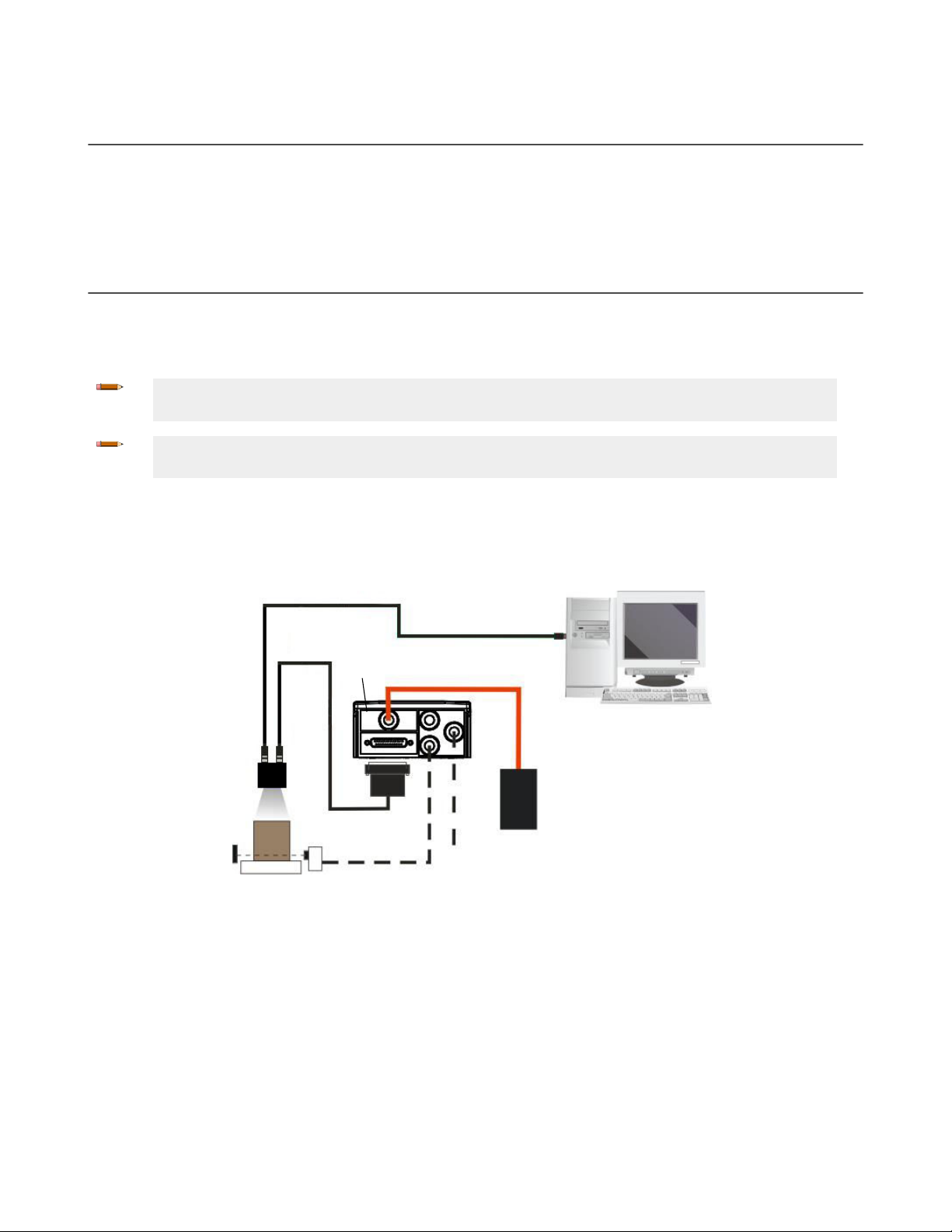
3.5.1 Ethernet Connection
The Ethernet connection is possible in two different layouts. In a Point-to-Point layout the reader is connected to a local
host by using a STP-M12D-4xx cable. There is no need to use a crossover adapter because ABR incorporates an autocross
function.
Figure 11. Ethernet Point-to-Point Layout
All devices always support multiple output channels (that is, for data monitoring).
When using a Local Area Network (LAN), one or more ABR readers can be connected to the network using STP-M12D-4xx
cables.
12 www.bannerengineering.com - Tel: + 1 888 373 6767
Page 13
Switch
Host
Power
TCNM-ACBB1
STP-M12D-4xx
ABR
1. Ethernet Interface
2. Main Serial Interface (Data Monitor)
3. External T
rigger (for One Shot or Phase Mode)
MQDEC-1703SS-DB25
ABR
Alone
External Power
for
ABR and I/O
Accessories
1. Main Serial Interface (RS232 or RS422 Full-Duplex)
2. Auxiliary Serial Interface (RS232 – Data Monitor)
3. External T
rigger (for One Shot or Phase Mode)
Host
TCNM-ACBB1
ABR 7000 Series Barcode Reader
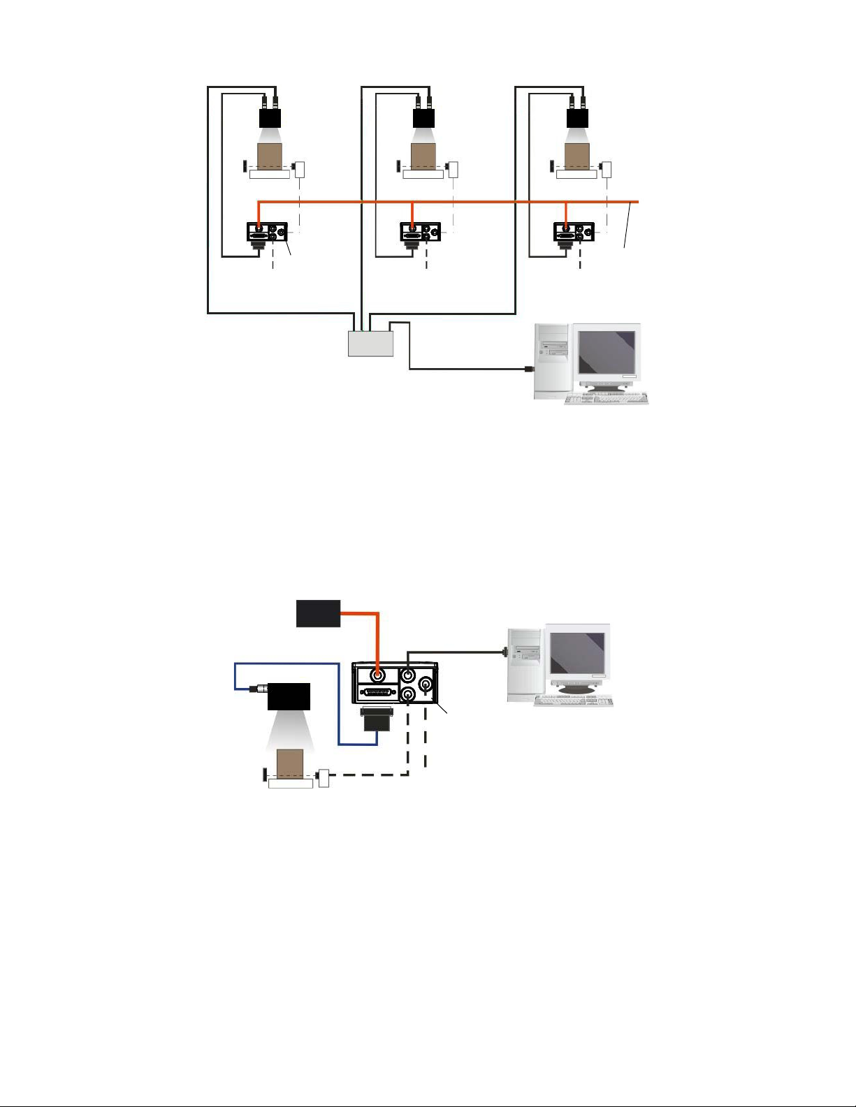
Figure 12. Ethernet Network Layout
3.5.2 Serial Connection
In this layout the data is transmitted to the Host on the main serial interface. The Ethernet interface can be used for reader
configuration by connecting a laptop computer running Barcode Manager.
Data can be transmitted on the RS232 auxiliary interface independently from the main interface selection to monitor data.
When One Shot or Phase Mode operating mode is used, the reader can be activated by an External Trigger (for example a
pulse from a photoelectric sensor) when the object enters the reading zone.
All devices always support multiple output channels (that is, for data monitoring).
3.5.3 Pass-Through
The pass-through layout allows each device working alone, to collect data from one or more pass-through input channels
and send this data plus its own on one or more different output channels.
In this way independent devices can be connected together in combinations to create multi device networks. Many devices
reading independently can send their messages through a common output channel which instead of being directed at a
Host can be collected by another device on its pass-through input channel and sent to a Host on a different output channel.
Figure 13. Serial Interface Point-to-Point Layout
www.bannerengineering.com - Tel: + 1 888 373 6767 13
Page 14
STP-M12D-4xx
MQDEC-1703SS-DB25
#1
Alone Alone Alone
#2 #3
Phase
Mode
Continuous
Mode
External
Trigger
Host
Switch
Power
1. Ethernet TCP/IP Server 1
2. Ethernet TCP/IP Server 2
3. Main Serial Interface (RS232 or RS422 Full-Duplex)
4. Aux Serial Interface (RS232)
= Pass-Through Input channel
= Output channel
TCNM-ACBB1
ABR 7000 Series Barcode Reader
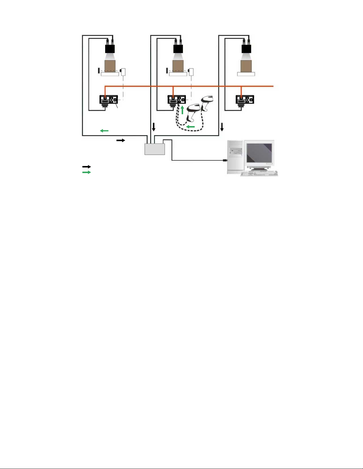
Figure 14. Pass-Through Layout
In a Pass-through layout each device supports multiple pass-through configurations to accept input from different devices
on different channels (middle reader, above). However, readers are not required to have a pass-through configuration if they
don’t need to receive data from an input channel (right reader, above). The overall data collection device always has at least
one pass-through configuration to collect the input data from the other devices and send it to the Host (left reader, above).
All devices always support multiple output channels (that is, for data monitoring).
In a Pass-through layout each device can have a different operating mode: Continuous, One Shot, Phase Mode, etc.
3.5.4 ID-NET Multidata Network (Pass-Through)
A special case of the pass-through layout allows each Slave device working alone, to collect data from one or more passthrough input channels and send this data plus its own on the ID-NET output channel to the Master.
The Slave readers are connected together using the ID-NET interface. Every Slave reader must have an ID-NET address in
the range 1-31.
The Master collects the data from its pass-through ID-NET input channel and sends it to the Host on a different output
channel.
14 www.bannerengineering.com - Tel: + 1 888 373 6767
Page 15

Alone
ID-NET
Master
STP-M12D-4xx
MQDEC-1703SS-DB25
AloneAlone
Host
Switch
ID-NET
Slave #2
ID-NET
Slave #1
Phase
Mode
External
T
rigger
Continuous
Mode
1. Ethernet TCP/IP Server 1
2.
ID-NET (up to 32 devices, max network extension of 1000 m)
3. Main Serial Interface (RS232 or RS422 Full-Duplex)
4. Aux Serial Interface (RS232)
= Pass-Through Input channel
= Output channel
TCNM-ACBB1
ABR 7000 Series Barcode Reader
Figure 15. ID-NET Multidata Layout (Pass-Through)
In a Pass-through layout each device supports multiple pass-through configurations to accept input from different devices
on different channels (Master reader, above). However, ID-NET Slave readers are not required to have a pass-through
configuration if they do not need to receive data from an input channel (right reader, above). The ID-NET Master always has
at least one pass-through
configuration to collect the ID-NET Slaves data and send it to the Host.
Note: Slave devices cannot receive data from a pass-through ID-NET input channel and Master devices
cannot send data on an ID-NET output channel.
All devices always support multiple output channels (that is, for data monitoring).
In a Pass-through layout each device can have a different operating mode: Continuous, One Shot, Phase Mode, etc.
3.5.5 ID-NET Synchronized Network
When the device is working Synchronized, the ID-NET connection is used to collect data from several readers to build a
multi-point or a multi-sided reading system; there can be one Master and up to 31 Slaves connected together.
The Slave readers are connected together using the ID-NET interface. Every slave reader must have an ID-NET address in
the range 1-31.
The Master reader is also connected to the Host on one of its communication channels. In the following examples the
RS232/RS422 main serial interface is used.
For a Master/Slave Synchronized layout the External Trigger signal is unique to the system; there is a single reading phase
and a single message from the Master reader to the Host computer. It is not necessary to bring the External Trigger signal
to all the readers.
In the Master/Slave Synchronized layout the Master operating mode can only be set to Phase Mode.
The Main and ID-NET interfaces are connected as shown in the following figures.
www.bannerengineering.com - Tel: + 1 888 373 6767 15
Page 16

ID-NET
Synchronized
Slave #n
ID-NET
Synchronized
Slave #1
ID-NET
Synchronized
Master
Host
Power
1. Main Serial Interface (RS232 or RS422 Full-Duplex)
2. External T
rigger
3. ID-NET (up to 16 devices - practical limit)
TCNM-ACBB1
ID-NET Synchronized
Slave #n
ID-NET Synchronized
Slave #1
ID-NET
Synchronized Master
Power
1. TCP/IP on-board Ethernet Interface
2. External T
rigger
3. ID-NET (up to 16 devices - practical limit)
Host
TCNM-ACBB1
ABR 7000 Series Barcode Reader
Figure 16. ID-NET Synchronized Layout
All devices always support multiple output channels (that is, for data monitoring).
The same
and ID-NET interfaces are connected as shown in the figure below.
configuration can be made to a Host using the on-board Ethernet interface to the Master. The TCP/IP Ethernet
3.6 Connector Descriptions
The connector pinouts and notes given in this section are for typical cabling applications.
3.6.1 Power, Communications, and I/O Connector
The ABR reader is equipped with an M12 17-pin male connector for connection to the power supply, serial interfaces, and
input/output signals. The details of the connector pins are indicated in the following table.
16 www.bannerengineering.com - Tel: + 1 888 373 6767
Figure 17. ID-NET Synchronized Layout with Master on-board TCP/IP Ethernet Interface to Host
Page 17

17
11
1
10
16
9
8
15
7
6
14
5
4
13
3
12
2
ABR 7000 Series Barcode Reader
Figure 18. M12/Euro-style 17-pin male Communications, I/O, and Power Connector
Table 2: Power and I/O Pinouts for MQDC2S-17xx
Pin Wire Color Description
1 Brown Power Supply Input Voltage +
2 Blue Power Supply Input Voltage -
3 White Input Signal 2 B (polarity insensitive)
8
4
Green Transmit Data of Auxiliary RS232
5 Pink External Trigger/Input 1 B (polarity insensitive)
6 Yellow External Trigger/Input 1 A (polarity insensitive)
7 Black ID-NET network +
8
8
Gray Configurable
9
Digital Output 2 - positive pin
NPN or PNP short circuit protected and software programmable
8
9
Red Configurable
Digital Output 1 - positive pin
NPN or PNP short circuit protected and software programmable
13 White/Green Input Signal 2 A (polarity insensitive)
8
14
15 White/Yellow ID-NET network -
Brown/Green Receive Data of Auxiliary RS232
9
16 Yellow/Brown Output 3
NPN or PNP short circuit protected and software programmable
Connector
n/a Cable shield connected to chassis and 17-pin connector shell
Case
RS232 Main Serial
RS422 FD Main Serial Interface
Interface
10 Violet - RX-
10
11 Gray/Pink RX RX+10
12 Red/Blue - TX-
17 White/Gray TX TX+
If using a TCNM-ACBB1 connection box, connect the reader using cable MQDEC-1703SS-DB25 and refer to for writing
details.
Use Cat 5e or superior M12 D-code cables, such as STP-M12D-4xx.
To meet EMC requirements:
Connect the reader chassis to the plant earth ground by means of a flat copper braid shorter than 100 mm
•
8
9
10
Referenced to GND; Outputs become opto-isolated and polarity sensitive when connected through the TCNM-ACBB1 connection box. See
TCNM-ACBB1 Electrical Connections
See
If using RS422, do not leave floating. See
ID-NET Network Termination
on page 21 for connection details.
on page 25 for information on resister termination.
RS422 Full-Duplex Interface
on page 23 for connection details.
www.bannerengineering.com - Tel: + 1 888 373 6767 17
Page 18

ABR 7000 Series Barcode Reader
• Connect pin "Earth" of the TCNM-ACBB1 connection box to a good earth ground
For direct connections, connect the cable shield to the locking ring nut of the connector
•
3.6.2 Inputs
There are two opto-isolated polarity insensitive inputs available on the M12 17-pin connector of the reader: Input 1 (External
Trigger) and Input 2, a generic input. See
The electrical features of both inputs are:
INPUT | V AB | Minimum | V AB | Maximum I IN Maximum
Open 0 V 2 V 0 mA
Closed 4.5 V 30 V 10 mA
The relative pins on the M12 17-pin connector are:
Pin Function
1 Power Supply input voltage +
2 Power Supply input voltage -
3 Input 2 B (polarity insensitive)
5 External Trigger B (polarity insensitive)
6 External Trigger A (polarity insensitive)
13 Input 2 A (polarity insensitive)
Inputs
on page 29 for more details.
3.6.3 Outputs
Three general purpose non opto-isolated but short circuit protected outputs are available on the M12 17-pin connector.
The pinout is the following:
Pin Function
9 Configurable
8 Configurable digital output 2
16 Configurable digital output 3
2 Power Supply Input Voltage -
The electrical features of the three outputs are the following:
Outputs
3 NPN/PNP/Push-Pull software selectable, reverse polarity and short circuit protected outputs available (2 Opto-isolated outputs instead if using
TCNM-ACBB1, see
Maximum Current: 100 mA maximum
Output Saturation Voltage (in PNP or NPN mode): < 3 V at 100 mA
Maximum load device voltage drop (in NPN mode): 30 V
Outputs
on page 33 for specifications)
The output signals are fully programmable being determined by the configured Activation/Deactivation events, Deactivation
Timeout or a combination of the two. For further details refer to the Help On Line page for the Output Setup step in Barcode
Manager.
CAUTION: For NPN output connections, the external interface voltage (Vext) must not exceed the ABR
power supply source voltage (Vdc) otherwise correct output functioning cannot be guaranteed.
digital output 1
18 www.bannerengineering.com - Tel: + 1 888 373 6767
Page 19

1
+
Output 1 *
Output 2 *
Output 3 *
Trigger A (polarity insensitive)
Trigger B (polarity insensitive)
Input 2 A (polarity insensitive)
Input 2 B (polarity insensitive)
AUX RS-232 RX
AUX RS-232 TX
MAIN RS-232 TX (RS-422 TX+)
MAIN RS-232 RX (RS-422 RX+)**
MAIN RS-422 TX –
MAIN RS-422 RX – **
ID-NET network +
ID-NET network –
–
+
–
2
1
2
9
8
16
6
5
13
3
14
4
7
15
17
11
12
10
1 – BN
2
– BU
3 – WH
4 – GN
5 – PK
6 – YE
7 – BK
8 – GY
9 – RD
10 – VT
11 – GY/PK
12 – RD/BU
13 – WH/GN
14 – BN/GN
15 – WH/YE
16 – YE/BN
17 – WH/GY
ABR7000
Input Power Supply
This is a typical example. Applications may vary.
Output Line Type set to PNP in Barcode Manager
If using RS-422, but not using RX+ and RX–, connect these two to –V dc or Ground
Load
Load
Load
10-30V dc
4.5-30V dc
*
**
ABR 7000 Series Barcode Reader
3.6.4 Wiring
Figure 19. PNP Inputs and Outputs
www.bannerengineering.com - Tel: + 1 888 373 6767 19
Page 20

1
+
Output 1 *
Output 2 *
Output 3 *
Trigger A (polarity insensitive)
Trigger B (polarity insensitive)
Input 2 A (polarity insensitive)
Input 2 B (polarity insensitive)
AUX RS-232 RX
AUX RS-232 TX
MAIN RS-232 TX (RS-422 TX+)
MAIN RS-232 RX (RS-422 RX+)**
MAIN RS-422 TX –
MAIN RS-422 RX – **
ID-NET network +
ID-NET network –
–
+
–
2
9
8
16
6
5
13
3
14
4
7
15
17
11
12
10
1 – BN
2
– BU
3 – WH
4 – GN
5 – PK
6 – YE
7 – BK
8 – GY
9 – RD
10 – VT
11 – GY/PK
12 – RD/BU
13 – WH/GN
14 – BN/GN
15 – WH/YE
16 – YE/BN
17 – WH/GY
ABR7000
Input Power Supply
This is a typical example. Applications may vary.
Output Line Type set to NPN in Barcode Manager
If using RS-422, but not using RX+ and RX–, connect these two to –V dc or Ground
Load
Load
Load
10-30V dc
4.5-30V dc
*
**
3
4
1
2
ABR 7000 Series Barcode Reader
3.6.5 Ethernet Connector
A Standard M12 D-Coded female connector is provided for the Ethernet connection. This interface is IEEE 802.3 10 BaseT
and IEEE 802.3u 100 BaseTx compliant.
Figure 20. NPN Inputs and Outputs
Figure 21. M12 D-Coded Female Ethernet Network Connector
20 www.bannerengineering.com - Tel: + 1 888 373 6767
Page 21

ABR 7000 Series Barcode Reader
Pin Name Function
1
2
3
4
TX +
RX +
TX RX -
Transmitted data (+)
Received data (+)
Transmitted data (-)
Received data (-)
3.6.6 Ethernet Interface
The Ethernet interface can be used for TCP/IP communication with a remote or local host computer by connecting the
reader to either a LAN or directly to a host PC. There is no need to use a crossover adapter since ABR incorporates an
auto-cross function.
A STP-M12D-4xx can be used to connect to a LAN.
On the ABR Ethernet interface the following communication channels are available:
•
TCP Client
• TCP Server
• UDP Channel
• FTP Client
The following Industrial Ethernet protocols are also available over the Ethernet interface:
• EtherNet/IP
• Modbus TCP Client
3.7 TCNM-ACBB1 Electrical Connections
All ABR models can be connected to a TCNM-ACBB1 connection box through the MQDEC-1703SS-DB25 accessory cable.
This cable terminates in an M12 17- pin connector on the ABR side and in a 25-pin male D-sub connector on the TCNMACBB1 side.
Make system connections through one of the TCNM-ACBB1 connection boxes because they offer the advantages of easy
connection, easy device replacement, opto-isolated outputs (Outputs 1 and 2), and filtered reference signals.
Note: If you require direct wiring to the reader, the connections are the same as shown in this section with
the exception of the digital Outputs. Direct wiring details are indicated in
Connector Descriptions
on page
16.
The table below gives the pinout of the TCNM-ACBB1 terminal block connectors. Use this pinout when the ABR is
connected by means of the TCNM-ACBB1.
TCNM-ACBB1 Terminal Block Connectors
Input Power
Vdc Power Supply Input Voltage +
GND Power Supply Input Voltage -
Earth Protection Earth Ground
Inputs
+V Power Source – External Trigger
I1A External Trigger A (polarity insensitive)
I1B External Trigger B (polarity insensitive)
-V Power Reference – External Trigger
+V Power Source – Inputs
I2A Input 2 A (polarity insensitive)
I2B Input 2 B (polarity insensitive)
-V Power Reference – Inputs
www.bannerengineering.com - Tel: + 1 888 373 6767 21
Page 22

ABR 7000 Series Barcode Reader
TCNM-ACBB1 Terminal Block Connectors
Outputs
+V Power Source - Outputs
-V Power Reference - Outputs
O1+ Output 1 + opto-isolated and polarity sensitive
O1- Output 1 - opto-isolated and polarity sensitive
O2+ Output 2 + opto-isolated and polarity sensitive
O2- Output 2 - opto-isolated and polarity sensitive
Auxiliary Interface
TX Auxiliary Interface TX
RX Auxiliary Interface RX
SGND Auxiliary Interface Reference
Shield
Shield Network Cable Shield
Main Interface
RS232 RS422 Full-Duplex
TX TX+
RX RX+
11
- TX-
- RX-
SGND SGND
Important: Do not connect GND and SGND to different (external) ground references. GND and SGND are
internally connected through filtering circuitry which can be permanently damaged if subjected to voltage
drops over 0.8 V dc.
Note: To avoid electromagnetic interference when the reader is connected to a TCNM-ACBB1 connection
box, verify the jumper positions in the TCNM-ACBB1 as indicated in p/n 174477
Installation Manual
, available at
www.bannerengineering.com
.
TCNM-ACBB1
3.7.1 Power Supply
Power can be supplied to the reader through the TCNM-ACBB1 spring clamp terminal pins.
The power must be between 10 V dc and 30 V dc only.
It is recommended to connect the device CHASSIS to earth ground (Earth) by setting the appropriate jumper in the TCNM-
ACBB1 connection box. See p/n 174477
TCNM-ACBB1 Installation Manual
, available at
www.bannerengineering.com
, for
details.
3.7.2 Main Serial Interface
The signals relative to the following serial interface types are available on the TCNM-ACBB1 spring clamp terminal blocks.
The main serial interface type and its parameters (baud rate, data bits, etc.) can be defined
Manager. For more details refer to the Help On Line page of the Reading Phase step (Channels) in Barcode Manager.
Details regarding the connections and use of the interfaces are given in the following sections.
by the user via Barcode
11
Do not leave floating. See
22 www.bannerengineering.com - Tel: + 1 888 373 6767
RS422 Full-Duplex Interface
on page 23 for connection details.
Page 23

1
5
9 6
13
2514
1
ABR 7000 Series Barcode Reader
RS232 Interface
The RS232 interface is generally used for Point-to-Point connections. When it is connected to the host computer it allows
transmission of code data.
The following pins are used for RS232 interface connection:
TCNM-ACBB1 Function
TX
RX
SGND
Transmit Data
Receive Data
Signal Ground
Shielded cables are recommended. The overall maximum cable length must be less than 15 m (49.2 ft).
RS422 Full-Duplex Interface
The RS422 full-duplex (5 wires + shield) interface is used for non-polled communication protocols in point-to-point
connections over longer distances (maximum 1200 m / 3940 ft) than those acceptable for RS232 communications or in
electrically noisy environments.
The TCNM-ACBB1 pinout follows:
TCNM-ACBB1 Function
TX+
RX+
TXRXSGND
RS422 Transmit Data +
RS422 Receive Data +
RS422 Transmit Data RS422 Receive Data Signal Ground
Note: For applications that do not use RS422 transmission to the reader (terminal block RX+ and RXsignals), do not leave these lines floating but connect them to SGND.
3.7.3 User Interface—Serial Host
The following table contains the pinout for standard RS232 PC Host interface. For other user interface types please refer to
their own manual.
RS232 PC-Side Connections
9-pin male connector
Pin Name Pin Name
2 RX 3 RX
3 TX 2 TX
5 GND 7 GND
25-pin male connector
www.bannerengineering.com - Tel: + 1 888 373 6767 23
Page 24

ABR 7000 Series Barcode Reader
3.7.4 ID-NET Interface
TCNM-ACBB1 Function
Shield
ID+
IDREF
Network Cable Shield
ID-NET network +
ID-NET network Network Reference
ID-NET Cables
The following instructions refer to the figures in
• The general cable type specifications
(or AWG 22) stranded flexible
It is recommend to use DeviceNet cables (drop or trunk type) to the following reference standards:
AN50325 – IEC 62026
UL STYLE 2502 80°C 30V
•
Cable Shield MUST be connected to earth ground ONLY at the Master
• NEVER use ID-NET cable shield as common reference
• The ID-NET max cable length depends on the baudrate used (see the Baudrate table, below)
• For Common Power Connections use only 2 wires (ID+ and ID-)
◦ DC Voltage Power cable (Vdc – GND) should be handled as a signal cable (that is, do not put it together with
AC cable)
◦ Wire dimensioning must be checked in order to avoid voltage drops greater than 0.8 Volts
◦ Cable should lie down as near as possible to the ID-NET cable (avoiding wide loops between them)
• Reader's chassis may be connected to earth
• Network inside the same building
Table 3: Baudrate
ID-NET Network Termination
are: CAT5 twisted pair + additional CAT5 twisted pair, shielded cable AWG 24
on page 25.
Baud Rate 125 kbps 250 kbps 500 kbps 1Mbps
Cable Length 1200 m 900 m 700 m Application
Note: The default ID-NET baudrate is 500 kbps. Lower ID-NET baudrates allow longer cable lengths.
dependent; contact
Banner Engineering for
details.
ID-NET Response Time
The following figure shows the response time of the ID-NET network. This time is defined as the period between the Trigger
activation and the beginning of data transmission to the Host.
24 www.bannerengineering.com - Tel: + 1 888 373 6767
Page 25

Max ID-NET Response Time
240
220
200
180
160
140
120
100
80
60
40
20
0
Response Time (ms)
Number of Nodes
500 kbps
250 kbps
125 kbps
0 1 2 3 4 5 6 7 8 9 10
11
12
13
14
15
16
ABR 7000 Series Barcode Reader
Figure 22. ID-NET Response Time
CONDITIONS
• ID-NET M/S Synchronized layout
• message length = 50 bytes per node
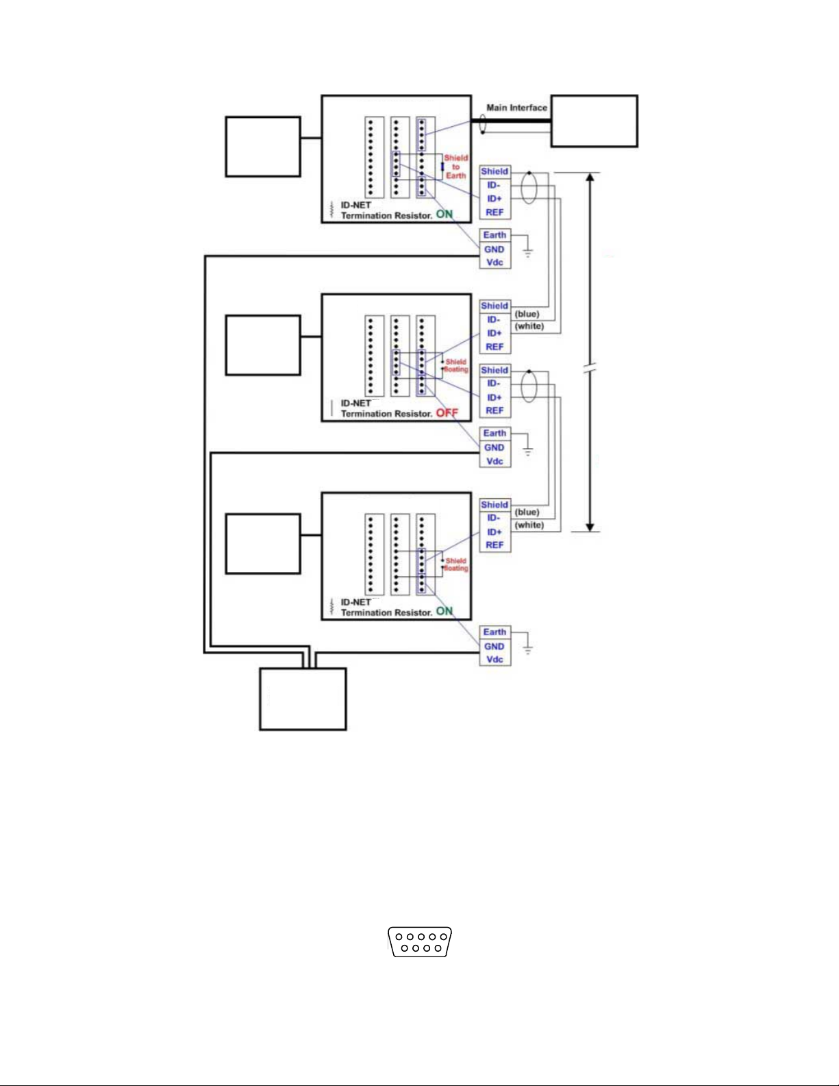
ID-NET Network Termination
The network must be properly terminated by a 120 Ohm resistor at the first and last reader of the network. This should be
done by setting the ID-NET Termination Resistance Switch in the TCNM-ACBB1 to ON.
www.bannerengineering.com - Tel: + 1 888 373 6767 25
Page 26

Reader
Master
Reader
Slave
#1
Reader
Slave
(up to 31)
TCNM-ACBB1
TCNM-ACBB1
HOST
RS232/RS422
ID-NET Cable
* Refer to Baudrate table for max. length
TCNM-ACBB1
External Power for ABR
and I/O Accessories
External Power for ABR
and I/O
Accessories
External Power for ABR
and I/O
Accessories
ABR 7000 Series Barcode Reader
Figure 23. ID-NET Network Connections with Isolated Power Blocks
26 www.bannerengineering.com - Tel: + 1 888 373 6767
Page 27

Reader
Master
Reader
Slave
#1
Reader
Slave
(up to 31)
Power
Source
(12-24 Vdc)
TCNM-ACBB1
TCNM-ACBB1
HOST
RS232/RS422
ID-NET Cable
* Refer to Baudrate table for max. length
TCNM-ACBB1
ABR 7000 Series Barcode Reader
Figure 24. ID-NET Network Connections with Common Power Branch Network
www.bannerengineering.com - Tel: + 1 888 373 6767 27
Page 28
Reader
Master
Reader
Slave
#1
Reader
Slave
(up to 31)
TCNM-ACBB1
TCNM-ACBB1
HOST
RS232/RS422
ID-NET Cable
* Refer to Baudrate table for max. length
TCNM-ACBB1
Power
Source
(12-24 Vdc)
5
9 6
1
ABR 7000 Series Barcode Reader
Figure 25. ID-NET Network Connections with Common Power Star Network
3.7.5 Auxiliary RS232 Interface
The RS232 auxiliary interface is available for Point-to-Point connections. When it is connected to the host computer it
allows transmission of code data.
The parameters relative to the auxiliary interface (baud rate, data bits, etc.) can be defined
(Channels) in Barcode Manager.
The 9-pin female auxiliary interface connector inside the TCNM-ACBB1 is the preferred connector for temporary
communication monitoring.
through the Reading Phase step
Figure 26. 9-pin female connector
If permanent system wiring is required, the following pins are used to connect the RS232 auxiliary interface:
28 www.bannerengineering.com - Tel: + 1 888 373 6767
Page 29

RX TX
Reference
USER INTERFACE
ABR 7000 Series Barcode Reader
TCNM-ACBB1 Function
RX
TX
SGND
Auxiliary Interface Receive Data
Auxiliary Interface Transmit Data
Auxiliary Interface Reference
Figure 27. RS232 Auxiliary Interface Connections
Note: Do not connect the Auxiliary Interface to the TCNM-ACBB1 spring clamp connectors and the 9-pin
connector simultaneously.
3.7.6 Inputs
There are two opto-isolated polarity insensitive inputs available on the reader: Input 1 (External Trigger) and Input 2, a
generic input.
The External Trigger can be used in One Shot Mode or in Phase Mode. Its main functions are:
Acquisition trigger in One Shot Mode
•
• Reading phase-ON/reading phase-OFF command in Phase Mode
The main functions of the general purpose Input 2 are:
• Second external trigger in Phase Mode
• Match code storage command when the Match Code option is enabled
The electrical features of both inputs are:
VAB = 30 V dc maximum
IIN = 10 mA (reader) + 12 mA (TCNM-ACBB1) maximum
The active state of these inputs are selected in software.
An anti-disturbance filter, by default, is implemented in software on both inputs. The value can be changed through the
software parameter Debounce Filter. See the Help On Line page of the Reading Phase step (Inputs) in Barcode Manager for
further details on these parameters.
These inputs are opto-isolated and can be driven by both NPN and PNP type commands.
Note: Polarity insensitive inputs assure full functionality even if pins A and B are exchanged.
The connections are indicated in the following diagrams:
www.bannerengineering.com - Tel: + 1 888 373 6767 29
Page 30

Jumper
Blue
Black
Brown
PNP Photoelectric Sensor
ABR 7000 Series Barcode Reader
TCNM-ACBB1 Function
+V
I1A
I1B
-V
Power Source - External Trigger
External Trigger A (polarity insensitive)
External Trigger B (polarity insensitive)
Power Reference - External Trigger
The yellow Trigger LED is on when the active state of the External Trigger corresponds to ON.
External Trigger Input Connections Using ABR Power
CAUTION: Power from the Vdc/GND spring clamps is available directly to the Input Device on the +V/-V
spring clamps, and does not pass through the Power Switch (ON/OFF) inside the TCNM-ACBB1.
Disconnect the power supply when working inside the TCNM-ACBB1.
Figure 28. PNP External Trigger Using ABR Power
30 www.bannerengineering.com - Tel: + 1 888 373 6767
Page 31

Jumper
Blue
Black
Brown
NPN Photoelectric Sensor
Pulled down to External
Input Device Reference
Input
Signal
PNP Photoelectric Sensor
ABR 7000 Series Barcode Reader
Figure 29. NPN External Trigger Using ABR Power
External Trigger Input Connections Using External Power
Figure 30. PNP External Trigger Using External Power
www.bannerengineering.com - Tel: + 1 888 373 6767 31
Page 32

Pulled up to External
Input Device Power
Input
Signal
NPN Photoelectric Sensor
Power to
Input Device
Input Input Device
Signal Reference
Input Device
Power to Input
Input Device Signal
Input Device
Reference
Input Device
ABR 7000 Series Barcode Reader
Figure 31. NPN External Trigger Using External Power
TCNM-ACBB1 Function
+V
I2A
I2B
-V
Power Source - Inputs
Input 2 A (polarity insensitive)
Input 2 B (polarity insensitive)
Power Reference - Inputs
Input 2 Connections Using ABR Power
CAUTION: Power from the Vdc/GND spring clamps is available directly to the Input Device on the +V/-V
spring clamps, and does not pass through the Power Switch (ON/OFF) inside the TCNM-ACBB1.
Disconnect the power supply when working inside the TCNM-ACBB1.
Figure 32. PNP Input 2 Using ABR Power
32 www.bannerengineering.com - Tel: + 1 888 373 6767
Figure 33. NPN Input 2 Using ABR Power
Page 33

Pulled down to External
Input Device Reference
Input
Signal
Input Device
Pulled up to External
Input Device Power
Input
Signal
Input Device
ABR 7000 Series Barcode Reader
Input 2 Connections Using External Power
Figure 34. PNP Input 2 Using External Power
Figure 35. NPN Input 2 Using External Power
3.7.7 Outputs
CAUTION: When Outputs 1 and 2 are connected through the TCNM-ACBB1 connection box, they
become opto-isolated and polarity sensitive and acquire the electrical characteristics listed below. To
function correctly, they require setting the Output Line Type
respective output. The hardware connection to the TCNM-ACBB1 can be either NPN or PNP.
Two general purpose outputs are available and their meaning can be defined by the user. They are typically used either to
signal the data collection result or to control an external lighting system.
The third output of an ABR 7000 is not accessible when using a TCNM-ACBB1 connection box.
TCNM-ACBB1 Function
+V
O1+
O1O2+
O2-
-V
The electrical features of the outputs are the following:
2 opto-isolated NPN or PNP, reverse polarity and short circuit protected outputs available
Power Source - Outputs
Output 1 + opto-isolated and polarity sensitive
Output 1 - opto-isolated and polarity sensitive
Output 2 + opto-isolated and polarity sensitive
Output 2 - opto-isolated and polarity sensitive
Power Reference Outputs
Maximum Current: 40 mA maximum continuous or 130 mA pulsed
Output Saturation Voltage (in PNP or NPN mode): < 1 V at 10 mA
Maximum load device voltage drop (in NPN mode): 30 V
configuration parameters to NPN for the
www.bannerengineering.com - Tel: + 1 888 373 6767 33
Page 34

Power to Output
Output device Signal
Output device
Reference
Output 1 Device
Power to Output
Output device Signal
Output device
Reference
Output 2 Device
Power to
Output device
Output device
Reference
Output 1 Device
Output
Signal
Power to
Output device
Output device
Reference
Output 2 Device
Output
Signal
Pulled up to External
Output Device Power
Output
Signal
Output 1 Device
Pulled up to External
Output Device Power
Output
Signal
Output 2 Device
ABR 7000 Series Barcode Reader
Power Dissipation: 90mW maximum at 50 °C (122 °F) ambient temperature
By default, Output 1 is associated with the No Read event, which activates when the code(s) signaled by the external trigger
are not decoded. Output 2 is associated with the Good Read event, which activates when all the selected codes are
correctly decoded.
The output signals are fully programmable being determined by the configured Activation/Deactivation events, Deactivation
Timeout or a combination of the two. Refer to the Barcode Manager parameters Help On Line for further details.
Output 1 and 2 Connections Using ABR Power
CAUTION: Power from the Vdc/GND spring clamps is available directly to the Output Device on the +V/V spring clamps, and does not pass through the Power Switch (ON/OFF) inside the TCNM-ACBB1.
Disconnect the power supply when working inside the TCNM-ACBB1.
Figure 36. PNP/Open Emitter Output Using ABR Power
Figure 37. NPN/Open Collector Output Using ABR Power
Output 1 and 2 Connections Using External Power
34 www.bannerengineering.com - Tel: + 1 888 373 6767
Figure 38. PNP/Open Emitter Output Using External Power
Page 35

Pulled down to External
Output Device Reference
Output
Signal
Output 1 Device
Pulled down to External
Output Device Reference
Output
Signal
Output 2 Device
ABR 7000 Series Barcode Reader
Figure 39. NPN/Open Collector Output Using External Power
Output 3 is not opto-isolated but can be assigned to the same events. By default it is not assigned to any event.
Note: For this output, set the Line Type configuration parameter according to the hardware connection to
the TCNM-ACBB1: NPN, PNP or Push-Pull.
www.bannerengineering.com - Tel: + 1 888 373 6767 35
Page 36

≥ 20%
≥ 40%
≥ 60%
≥ 75%
≥ 95%
ABR 7000 Series Barcode Reader
4 Smart Teach Interface
Smart Teach is designed to improve ease of installation and maintenance
Status information is clearly presented by means of the five colored LEDs. The single push button provides access to the
following modes.
• Test includes bar graph visualization to check static reading performance
• Aim/Autofocus turns on the laser pointers to aid positioning and focusing
• Setup self-optimizes and auto-configures image brightness parameters
• Learn automatically detects and recognizes a single code which is presented to it. Successive Learns will substitute
the current code. To configure multiple codes, use the Barcode Manager Auto-learn procedure
Quick access to the following modes is provided by using the push button:
1.
Press the button. The Status LED gives visual feedback.
2. Hold the button until the specific mode LED is on (Test, Aim/Autofocus, Setup, or Learn).
3.
Release the button to enter the specific mode.
After the button is pressed, the cycle of LED activation is as follows:
Release button to exit Release button to enter Test mode
Release button to enter Setup mode Release button to enter Learn mode Release button to exit (cycle)
Release button to enter Aim/Autofocus
mode
4.1 Test Mode
Test mode can be used to test the reading performance of the system. Use a code suitable for your application.
Enter the Test function by pressing and holding the Smart Teach button until the Test LED is on.
1.
2. Release the button to enter the Test function.
Once entered, the bar graph on the five LEDs is activated and if the reader starts reading codes the bar graph
shows the good read rate.
Figure 40. Smart Teach Interface: Test Function
The bar graph has the following meaning, referring to the actual percentage of good reads:
In case of No Read condition, only the Status LED (red) is on and blinks.
36 www.bannerengineering.com - Tel: + 1 888 373 6767
Figure 41. Test Function Bar Graph
Page 37

ABR 7000 Series Barcode Reader
3. To exit the test, press the Smart Teach button once.
Note: By default, the Test exits automatically after three minutes.
4.2 Aim—Manual Focus Models
The Aim function turns on the built-in laser pointer aiming system to aid reader positioning. Because the laser pointers are
centered on the FOV, use them to position the imager on the code. The Aim LED blinks to indicate this state.
1.
Select a single code for your application and place at the correct reading distance for your application.
See the
2. Enter Aim mode by pressing and holding the Smart Teach button until the Aim LED is on.
3. Release the button to enter Aim mode.
The laser pointers turn on.
4. Position the code at the center of the Field of View (equidistant from the laser pointers).
Global FOV Diagrams
on page 82 for reference.
Figure 42. Smart Teach Interface: Aim Mode
Figure 43. Code Position
5. Once aligned, exit Aim mode by pressing the Smart Teach button once.
After a short delay, Aim mode is cancelled and the laser pointers turn off.
4.3 Aim and Autofocus the Reader—Liquid Lens Autofocus Models
The Aim/Autofocus function turns on the built-in laser pointer aiming system to aid reader positioning. Because the laser
pointers are centered on the FOV, use them to position the imager on the code. The Aim LED blinks to indicate this state.
For Liquid Lens Autofocus models, the autofocus feature is incorporated into this function.
For best results, print the
1.
Using this chart during Focus Autolearn typically results in a more accurate focus/reading distance, a more accurate
PPI value and more accurate module size measurements of barcodes.
2. Place the PPI (Pixels Per Inch) Setup Chart in front of the reader at the correct reading distance for your application.
See the Global FOV Diagrams in
3. Enter Aim/Autofocus mode by pressing and holding the Smart Teach button until the Aim LED is on.
4. Release the button to enter the Aim function.
The laser pointers turn on, and the Autofocus procedure begins. The Aim LED blinks until the procedure is
complete.
PPI (Pixels Per Inch) Setup Chart
on page 120.
Liquid Lens Autofocus Models 9 mm Lens
Figure 44. Smart Teach Interface: Aim/Autofocus Function
on page 83 for reference.
www.bannerengineering.com - Tel: + 1 888 373 6767 37
Page 38

0.30 mm
ABR 7000 Series Barcode Reader
5. Within 3 seconds (before the reader flashes),
the Field of View (equidistant from the laser pointers). The code must not move during this procedure.
The Autofocus procedure ends when the Reading Distance and PPI values are successfully saved in the reader
memory, the Aim LED stops blinking and ABR 7000 emits three high pitched beeps.
If the Autofocus cannot be reached after a timeout of about 3 minutes, the ABR 7000 exits without saving the
parameters to memory, the Aim LED stops blinking, and the ABR 7000 emits a long low pitched beep.
position the code closest to your application code size at the center of
Figure 45. Code Position
4.4 Setup
Once entered, the imager automatically performs the Image Acquisition parameter calibration for the specific code
presented to it.
1.
Enter Setup mode by pressing and holding the Smart Teach button until the Setup LED is on.
Figure 46. Smart Teach Interface: Setup Mode
2. Release the button to enter Setup mode.
The Setup LED blinks until the procedure is completed. The Setup procedure ends when the Image Acquisition
parameters are successfully saved in the reader memory, the Setup LED stops blinking, and the ABR emits three
high pitched beeps.
3. If the calibration cannot be reached after a timeout of about 5 (five) seconds, ABR exits without saving the
parameters to memory, the Setup LED stops blinking, and the ABR emits a long low pitched beep.
4.5 Learn
Once entered, the imager starts a procedure to automatically detect and recognize a single code13 which is presented to it.
Successive Learns will substitute the current code. To configure multiple codes, use the Barcode Manager Auto-learn
procedure.
Exit Learn mode at any time by pressing the Smart Teach button once. After a short delay the Learn procedure is cancelled.
1. Enter Learn mode by pressing and holding the Smart Teach button until the Learn LED is on.
Figure 47. Smart Teach Interface: Learn Mode
2. Release the button to enter Learn mode.
The Learn LED blinks until the procedure is complete. The Learn procedure ends when the Image Processing and
Decoding parameters for a single code are successfully saved in the reader memory, the Green Spot is activated,
the Learn LED stops blinking, and the ABR emits 3 high pitched beeps.
Note: The PPI (Pixels Per Inch) Setup Chart cannot be used to set the Code 128 symbology (even though
the reader successfully reads the code). Use the application-specific code if you need to set this
symbology.
Note: If you have used this procedure to
configure the ABR, go to
Test Mode
on page 36.
13
The Learn procedure does not recognize the following symbologies: Postal Codes, Pharmacode, MSI, Standard 2 of 5, or Matrix 2 of 5. Configure
through Barcode Manager for these codes.
38 www.bannerengineering.com - Tel: + 1 888 373 6767
Page 39

ABR 7000 Series Barcode Reader
5 Getting Started
Power up the sensor, and verify that the power LED is on blue. Ethernet models only: verify that the Ethernet indicator is on
amber to verify the Ethernet connection.
5.1 Install Barcode Manager
Administrative rights are required to install the Barcode Manager software.
Important: Install Barcode Manager on a Windows® XP, 7, 8, or 1014 computer. Barcode Manager does
not currently support Windows Embedded (often used in industrial PCs and/or PLCs).
1. Download the latest version of Barcode Manager from
2. Navigate to and open the downloaded file.
3. Run Barcode Manager_Setup.exe to access the installation screen.
4.
Follow the onscreen installation procedure.
After the installation is complete, the Barcode Manager entry is created under Start > Programs > Banner
Engineering. A desktop icon is also created.
www.bannerengineering.com
.
5.2 Ethernet Device Discovery
The following configuration procedure assumes that a laptop computer running Barcode Manager is connected to a factory
default reader through the Ethernet port.
The Barcode Manager user interface opens and displays a list of all the devices belonging to the Local Area Network (LAN).
Figure 48. Device Discovery
The Barcode Manager discovery feature also shows devices not belonging to the LAN and displays them in light gray (see
Figure 48
The following is an example configuration for Windows® operating system version 7, 8, or 10.
on page 39).
14
Microsoft and Windows are registered trademarks of Microsoft Corporation in the United States and/or other countries.
www.bannerengineering.com - Tel: + 1 888 373 6767 39
Page 40

ABR 7000 Series Barcode Reader
1. Confirm
the network connections. Changing the Local Area Connection (LAN) properties of the programming
computer to be compatible with the ABR device on the network may be required for connection.
a) Click the Start button, then on the Start menu, click Control Panel or search for Control Panel.
b) In Control Panel, click Network and Internet, then click Network and Sharing Center, and then click Change
adapter settings.
c) Right-click on the connection that you want to change, then click Properties.
If you are prompted for an administrator password or
confirmation, enter the password or provide confirmation.
d) In the connection properties, click Internet Protocol Version 4 (TCP/IPv4), and then click Properties.
Figure 49. Local Area Connection Properties
e) In the Internet Protocol (TCP/IPv4) Properties, select Use the following IP address.
f) Make sure that the IP address is 192.168.3.1, and the subnet mask is 255.255.255.0.
The IP address must be compatible with the default device address 192.168.3.100.
2. As an alternate method, change the IP address of the device.
a) Add the device to the LAN by aligning its IP Address to the network. The network administrator should provide
valid LAN address(es).
b)
Click the
c)
Change the Ethernet Settings (IP Address, Subnet Mask, Gateway Address, etc.) according to the network
device wrench icon to open the Device Environment Configuration window.
requirements.
d) Click OK.
3.
In Barcode Manager, click
Find Devices.
The device displays in Sensor Neighborhood with a dark gray icon, meaning it is now part of the LAN and can be
configured. The new IP address also displays.
4.
Double-click or drag the device icon into the Selected Device Information Area.
Details about the device display in this area.
Figure 50. Device Selection—Selected Device Details
After device discovery, configure your device through Barcode Manager.
40 www.bannerengineering.com - Tel: + 1 888 373 6767
Page 41

ABR 7000 Series Barcode Reader
5.3 Serial Device Discovery
Note: Although this feature allows all devices to be configured through their Serial Interface, be aware that
transmission speeds and some Barcode Manager features are limited when using this interface. It is
advised to use the Ethernet interface whenever possible.
Serial Device Discovery is not enabled by default.
In Barcode Manager, from the main menu go to Options > UI Settings window.
1.
2. Click on the Global Settings menu and scroll down to the Find Devices section.
3. Select Enable Serial Device Discovery.
Additional options become available, including Serial Parity, Serial Databits, Serial Stop Bits, and Baud Rates.
4. Scroll down to see the options.
5. Select the Serial communication parameters according to your application.
The default is 115200.
Note: If you’re not sure of the Serial baud rate, select Enable Automatic Device Discovery which for
serial devices will try communication at all baud rates, but only at No parity, 8 data bits;1 stop bit.
Enabling this parameter can notably lengthen discovery time. In general it is better to disable it to
increase discovery efficiency.
6. Click OK to return to Barcode Manager.
7.
Click the Getting Started icon.
Open the Serial Devices tab.
8.
9.
Drag the
The device is now connected to the Barcode Manager Configuration environment. Configure your device through
Barcode Manager.
device icon into the Selected Device Information area.
www.bannerengineering.com - Tel: + 1 888 373 6767 41
Page 42

ABR 7000 Series Barcode Reader
6 Device Configuration
6.1 Automatic Setup
To begin
configuration, the reader must be correctly mounted at the correct reading distance for your application so that its
Field of View covers the application reading area.
Note: For Manual Adjustable Focus models go to
Advanced Setup for Manual Adjustable Focus Models
on page 46.
Automatic Setup provides an automatic procedure for setting optical/illumination and code definition parameters to obtain
the most stable decoding conditions for a single code symbology based on the images presented to the reader. It can be
set to include Image Filters if necessary. See the table below for codes and filters managed by Automatic Setup. Automatic
Setup is especially useful for DPM applications.
Enabled 1D Codes Enabled 2D Codes Enabled Filters
Code 128
EAN 128
Code 39
Code 93
Codabar
PDF417
MICRO PDF417
GS1 DataBar
1.
Click Open Device
GS1 DataBar Stacked
GS1 DataBar Limited
GS1 DataBar Expanded
GS1 DataBar Expanded Stacked
UPCEAN Family EAN13
UPCEAN Family EAN8
UPCEAN Family UPCA
UPCEAN Family UPCE
Data Matrix ECC 200
QR
Micro QR
Aztec
MAXICODE
DOTCODE
Erode 3×3, 5×5 and 7×7
Dilate 3×3, 5×5 and 7×7
Smoothing
Configuration. The Open Device Configuration window opens showing the list of
configurations (jobs) currently saved on the device. For new devices, the only saved configuration is the Default
configuration.
2. Click OK. The device enters continuous mode and begins acquiring images.
3.
Place the application code in front of the reader at the correct application reading distance.
4. If needed, focus the reader on the code.
5.
After the code is positioned, click
Pause to stop image acquisition.
Note: If the image display area is too dark to see the images being captured, drag the Gain and
Exposure Time sliders to the right to increase visibility. This will not affect Automatic Setup.
Figure 51. Gain and Exposure Time
42 www.bannerengineering.com - Tel: + 1 888 373 6767
Page 43

ABR 7000 Series Barcode Reader
6. Click Start Automatic Setup. The Automatic Setup window opens.
Figure 52. Automatic Setup
7. Select the correct reading conditions.
• Static Tuning—No maximum limit on exposure time
• Dynamic Tuning—Maximum allowable image exposure is automatically calculated using the parameters
• 1D code
• 2D code
• Include Image Filtering—Select to find
8. Click Start.
The reader begins acquiring images, adjusting the brightness and focus (for liquid lens autofocus models), and
adjusting the decoding settings to find a barcode and optimize reading for the first code it finds. At the end of the
procedure the Status: Completed message displays.
9.
Close the Automatic Setup window.
Your reader is now optimized for decoding. Continue setting up the reader for your application as desired. Typically,
Reading Phase is configured next. See
the best decoding condition.
Reading Phase
on page 50.
6.2 Advanced Setup for Liquid Lens Autofocus Models
Advanced Setup provides access to the complete array of optical/illumination and code definition
fine-tuned semi-automatically and manually to obtain the best results for applications of any complexity. If your application
requires multiple code symbologies, multiple image settings, Code Grading, or other parameter settings for decoding, use
the Advanced Setup.
To begin configuration, the reader must be correctly mounted at the correct reading distance for your application so that its
Field of View covers the application reading area.
Note: For manual adjustable focus models go to
page 46.
1. From the Task Area select Open Device Configuration.
The Open Device Configuration window opens showing the list of currently saved configurations (jobs) saved on the
device. For new devices, the only saved job is the Default configuration.
2. Click OK.
The device enters run mode and begins acquiring images.
3. Click Advanced Setup.
4.
Click the Play
5. Place the PPI (Pixels per Inch) Setup Chart in the reading area.
icon.
Advanced Setup for Manual Adjustable Focus Models
parameters that can be
on
www.bannerengineering.com - Tel: + 1 888 373 6767 43
Page 44

ABR 7000 Series Barcode Reader
6.
After the chart is positioned, click Pause to stop image acquisition.
Figure 53. Chart Positioned
7. Click Image Settings.
8.
Click
Select the reading option.
9.
Image Auto Setup to automatically acquire the best exposure time and gain values.
• Static reading—No maximum limit on exposure time
• Dynamic reading—Maximum allowable image exposure is automatically calculated using the parameters
Figure 54. Image Auto-Setup Window
Note: For applications having multiple lighting or code reading conditions, up to 10 different Image
Setups can be
configured by adding them with the
icon.
10. Click Start.
Click Apply.
11.
44 www.bannerengineering.com - Tel: + 1 888 373 6767
Page 45

ABR 7000 Series Barcode Reader
12.
Click Focus Autolearn.
Tip: You may have to click Image Settings again before you can click Focus Autolearn.
Note: The Reading Distance value is not significant until the Focus Autolearn procedure ends
successfully.
The Calibrate dialog box opens allowing you to start the procedure.
Click Start.
13.
At the end of the calibration you can see the new Reading Distance and Image Density (PPI) values as well as the
FOV dimensions.
14. Click Apply.
Note: To enlarge the visual image of the code view, click the zoom image icon, repositioning it
on the code.
Note: At this point it is good practice to save the
permanent memory, giving it a specific name.
15. Place an
application-specific code in front of the reader and only click Image Auto-Setup to register any changes in
lighting or code surface contrast.
Figure 55. Reading Distance, Image Density, and FOV Dimensions
configuration from temporary memory to
www.bannerengineering.com - Tel: + 1 888 373 6767 45
Page 46

ABR 7000 Series Barcode Reader
16. Click the Data Matrix ECC 200 symbology under the Image Settings branch (enabled by default).
If this symbology is among those in your application it will be shown in the image display with its code symbology
name and a small green box around it indicating it is decoded.
Figure 56. Decoded Data Matrix ECC 200
Note: The large green box for each symbol indicates the code localization area which by default is
equal to the maximum FOV. Resize and move the box by dragging its borders with the mouse. The
code must be found within this area in order to be decoded.
17. Add your application specific codes to the Code Settings by selecting them from the icons over the Configuration
Parameters tree area.
18.
If the Data Matrix symbology is not used, delete it from the Code Settings with the icon.
19.
If you don’t know the code type, use the Code Autolearn feature by clicking on the
icon15.
See the Barcode Manager Instruction Manual (p/n 207635) for details.
Continue the configuration using
Reading Phase
on page 50.
6.3 Advanced Setup for Manual Adjustable Focus Models
Advanced Setup provides access to the complete array of optical/illumination and code definition parameters that can be
fine-tuned semi-automatically and manually to obtain the best results for applications of any complexity. If your application
requires multiple code symbologies, multiple image settings, Code Grading, or other parameter settings for decoding, use
the Advanced Setup.
To begin configuration, correctly mount the reader so that its Field of View (FOV) covers the application reading area.
Note: For Liquid Lens Autofocus models go to
43.
1. From the Task Area select Open Device
Configuration.
The Open Device Configuration window opens showing the list of currently saved configurations (jobs) saved on the
device. For new devices, the only saved job is the Default configuration.
2. Click OK.
The device enters run mode and begins acquiring images.
Advanced Setup for Liquid Lens Autofocus Models
on page
15
The Code Autolearn procedure does not recognize the following symbologies: Pharmacode, MSI, Standard 2 of 5, Matrix 2 of 5.
46 www.bannerengineering.com - Tel: + 1 888 373 6767
Page 47

ABR 7000 Series Barcode Reader
3. Click Advanced Setup.
4.
Click the Play icon.
Place the PPI (Pixels per Inch) Setup Chart in the reading area. See
5.
6.
After the chart is positioned, click the
Pause icon to stop image acquisition.
PPI (Pixels Per Inch) Setup Chart
on page 120.
Figure 57. Chart Positioned
Note: If the image display area is too dark to see the images being captured, drag the Gain and
Exposure Time sliders to the right to increase visibility. This will not affect Automatic Setup.
7. Click Image Settings.
8.
Click Image Auto-Steup to automatically acquire the best exposure time and gain
values.
Select the reading option.
9.
• Static reading —No maximum limit on exposure time
• Dynamic reading—Maximum allowable image exposure is automatically calculated using the parameters
Figure 58. Image Auto-Setup Window
10. Click Start.
11. Click Apply.
Note: For applications having multiple lighting or code reading conditions, up to 10 different Image
Settings can be
www.bannerengineering.com - Tel: + 1 888 373 6767 47
configured by adding them with the
icon.
Page 48

ABR 7000 Series Barcode Reader
12. From the main menu open Options > UI Settings > Configuration tab.
Select Focus Calibration under View Window if it is not already selected.
13.
Figure 59. UI Settings
48 www.bannerengineering.com - Tel: + 1 888 373 6767
Page 49

ABR 7000 Series Barcode Reader
14. Click the Focus Calibration tab at the bottom of the window.
Note: This feature is only available for manual focus models.
The oscilloscope view is shown in the bottom panel and can be used for manual focus adjustment.
Figure 60. Oscilloscope View
The red line in the image panel above the oscilloscope must pass through the code. Click and drag the red line
vertically to reposition it over the code.
Note: To enlarge the visual image of the code and the oscilloscope views, drag the Focus
Calibration window up and click the zoom image
icon repositioning it on the code.
While in run mode, manually adjust the focus until the bars relative to the code in the oscilloscope demonstrate their
maximum length (focus).
You can also see the visual focus on the code view.
Figure 61. Code View and Oscilliscope View Zoomed In
When focused, click
www.bannerengineering.com - Tel: + 1 888 373 6767 49
Pause to stop image acquisition.
Page 50

ABR 7000 Series Barcode Reader
15.
Click Acquire PPI to automatically set the Image Density so that the ABR functions correctly
and to the fullest extent of its capabilities.
This procedure is necessary to enable transmitting accurate barcode size estimates for barcodes at the same
reading distance as the test card.
Note: At this point it is good practice to save the configuration from temporary memory to
permanent memory, giving it a specific name.
16. Place an
application-specific code in front of the reader and only click Image Auto-Setup to register any changes in
lighting or code surface contrast.
Do not repeat Focus Calibration or PPI.
17. Click the Data Matrix ECC 200 symbology under the Image Settings branch (enabled by default).
If this symbology is among those in your application it will be shown in the image display with its code symbology
name and a small green box around it indicating it is decoded.
Figure 62. Decoded Image
Note: The large green box for each symbol indicates the code localization area which by default is
equal to the maximum FOV. Resize and move the box by dragging its borders with the mouse. The
code must be found within this area in order to be decoded.
18. Add your application-specific codes to the Code Settings by selecting them from the icons over the Configuration
Parameters tree area.
19.
If the Data Matrix symbology is not used, delete it from the Code Settings with the
20.
If you don’t know the code type, use the Code Autolearn feature by clicking on the icon16.
icon.
See the Barcode Manager Instruction Manual for details.
21.
For each code symbology set the relative parameters according to your application.
Continue the configuration using
Reading Phase
on page 50.
6.4 Reading Phase
1.
Click
16
The Code Autolearn procedure does not recognize the following symbologies: Pharmacode, MSI, Standard 2 of 5, Matrix 2 of 5.
50 www.bannerengineering.com - Tel: + 1 888 373 6767
Reading Phase.
Page 51

ABR 7000 Series Barcode Reader
2. Select your
•
•
•
Continuous Mode and Acquisition Trigger are shown by default.
3. Configure
Different groups appear in the panel depending on the selected icons over the Configuration Parameters tree area.
application-specific Operating Mode from the icons over the Configuration Parameters tree area:
Continuous
One Shot
Phase Mode
the relative Operating Mode parameters from the Reading Phase parameters panel.
6.5 Good Read Setup
1.
Click Good Read Setup.
2. Select your
•
•
•
•
Not all data collection types are available for all Operating Modes. Incompatible data collection types are shown in
gray and cannot be selected.
The following example shows Code Combination. By default, the Expected Codes (when more than one code type
is selected), are in logical AND, which means that all codes are required to be decoded to produce a Good Read
condition.
specific data collection type from the icons over the Configuration Parameters tree area:
Code Collection
Code Combination
Code Presentation
Match Code
Figure 63. Good Read Setup: Code Combination
www.bannerengineering.com - Tel: + 1 888 373 6767 51
Page 52

ABR 7000 Series Barcode Reader
3. If a Good Read condition should be produced when any single code is decoded, independent from the others,
combine them in logical XOR.
Drag the code icon(s) from their relative Expected Code box into the Expected Code box of the XOR
a)
combination you wish to create.
b) Delete the empty box by selecting it with the mouse (highlighted) and pressing delete on your keyboard.
Figure 64. Code Combination
c)
To create a logical AND condition from a logical XOR, create a new Expected Code box using the
Drag the desired code icon from one box to the other.
d)
icon.
Figure 65. New Expected Code
6.6 Data Formatting
For details, see the Barcode Manager Instruction Manual, available at
1. Click Data Formatting.
www.bannerengineering.com
.
52 www.bannerengineering.com - Tel: + 1 888 373 6767
Page 53

ABR 7000 Series Barcode Reader
2. Configure your application-specific Data Formatting Message(s) from the Configuration
Message 1, Message 2, etc.
Parameters tree area:
Figure 66. Data Formatting
3. Add fields to the output message by clicking on the icons above the Message Field area.
The fields are appended to the message.
4. Drag the
fields to position them between other fields in the message so that the output message is ordered
according to your application requirements.
Each field has its own relative configuration parameters in the parameters panel.
www.bannerengineering.com - Tel: + 1 888 373 6767 53
Page 54

ABR 7000 Series Barcode Reader
6.7 Output Setup
1. Configure
Parameters tree area: Output 1, Output 2, etc.
your application-specific Digital Output(s) and Green/Red Spots (if used) from the Configuration
Figure 67. Output Setup
2. Save the configuration from temporary memory to permanent memory, overwriting the previously saved
configuration.
6.8 Fine-Tuning Examples
The following examples show some of the typical conditions occurring during the installation and how they can be tuned
manually.
6.8.1 Under-Exposure
To correct an under-exposure result it is recommended to change the following parameters in their order of appearance:
1.
Increase the Exposure Time.
2. Increase the Gain.
Note: In general, a longer exposure time corresponds to a lighter image but is susceptible to blurring due
to code movement. Exposure time is also limited by the Internal Lighting mode parameter. Longer
exposure times can be set if the power strobe level is lowered.
High gain settings may produce a grainy image that may affect the decoding process.
54 www.bannerengineering.com - Tel: + 1 888 373 6767
Page 55

ABR 7000 Series Barcode Reader
Figure 68. Example Under Exposure: Too Dark
6.8.2 Over-Exposure
To correct an over-exposure result, change the following parameters in order:
1. Decrease the Gain.
2. Decrease the Exposure Time.
www.bannerengineering.com - Tel: + 1 888 373 6767 55
Page 56

ABR 7000 Series Barcode Reader
Figure 69. Example Over Exposure: Too Light
6.8.3 Code Moving Out of the FOV
To correct code moving out of the FOV and have the code completely visible in FOV, follow one or both of the following
options:
• Reposition the reader
• Use the Delay on Trigger and set the Time or Space values
56 www.bannerengineering.com - Tel: + 1 888 373 6767
Page 57

ABR 7000 Series Barcode Reader
Figure 70. Example of Code out of the FOV
Figure 71. Add Delay on Trigger to Correct Out of FOV
www.bannerengineering.com - Tel: + 1 888 373 6767 57
Page 58

ABR 7000 Series Barcode Reader
7 Advanced Reader Configuration
For further details on advanced product
Barcode Manager Help menu.
configuration, refer to the Barcode Manager Instruction Manual available in the
7.1 Host Mode Programming
The reader can also be remotely
See the Host Mode Programming Manual, available at
configured from a host system using the Host Mode programming command language.
www.bannerengineering.com
.
58 www.bannerengineering.com - Tel: + 1 888 373 6767
Page 59

ABR 7000 Series Barcode Reader
8 Industrial Ethernet Overview
The ABR reader can be monitored and controlled using Industrial Ethernet protocols (EtherNet/IP or Modbus/TCP). On the
monitoring side, the ABR makes the barcode data output string configured
or HMI along with eight user-defined output bits. These output bits can be configured to report the current status of the
ABR, including Good Read, No Read, etc. or to report the status of an input bit.
Control of the ABR using Industrial Ethernet is possible using eight user-defined input bits. These can be configured as
Reading Phase On, Reading Phase Off, Acquisition Trigger, or they can control an output bit.
Input command strings cannot be sent to the ABR using Industrial Ethernet, but trigger and Host Mode Programming
commands can be sent to the TCP server channel by a socket connection.
on the Data Formatting page available to a PLC
8.1 Industrial Ethernet Setup in Barcode Manager
8.1.1 Set the Industrial Ethernet Protocol (EtherNet/IP, Modbus/TCP)
The Industrial Ethernet communication channel is disabled by default.
To enable this channel, use the following instructions.
1.
From the Reading Phase, Data Formatting, or Output Setup pages, click Add New Industrial Protocol.
Note: This option is available only for Installer-Expert users.
2. Select one of the choices:
•
EtherNet/IP
• Modbus/TCP
3.
After changing the settings, click
with the new settings.
Play, Monitor, or Getting Started to activate Industrial Communications
8.1.2 Industrial Ethernet Reading Phase Control
The Industrial Ethernet host controller can control the reading phase by assigning individual communication bits to reading
phase parameters. These bits are received on the Industrial Ethernet channel as Input Bits.
To control the reading phase start and end using Industrial Protocol Input Bits, use the following instructions:
www.bannerengineering.com - Tel: + 1 888 373 6767 59
Page 60

Industrial Ethernet Bits
ABR 7000 Series Barcode Reader
1.
Go to Reading Phase > Phase Mode > Phase On and select an input bit from the Industrial Protocol Input Bit list.
In this example, select Bit 2.
Figure 72. Industrial Ethernet Input Bits Configured for Phase On Control
2. Click Phase Off, and select the same bit used in step 1 from the Industrial Protocol Input Bit list.
3. Change selected bit polarity from Leading to Trailing.
The reading phase will start when the input bit goes high, and end when the input bit goes low.
Figure 73. Industrial Ethernet Input Bits Configured for Phase Off Control
60 www.bannerengineering.com - Tel: + 1 888 373 6767
Page 61

Industrial Ethernet Bits
ABR 7000 Series Barcode Reader
8.1.3 Industrial Ethernet Reading Phase Acquisition Control
To acquire individual images using an Industrial Protocol Input Bit, use the following instructions:
1.
Go to Reading Phase > Phase Mode > Acquisition Trigger and select Trigger Type as External.
The External Trigger Source list displays.
Select an Industrial Protocol Input Bit.
2.
In this example, select Bit 6.
Because the selected bit polarity is set to Leading, the ABR will take an image each time the input bit goes high.
Figure 74. Industrial Ethernet Strings and Bits
8.1.4 Industrial Ethernet Digital Output Control
The Industrial Ethernet host controller can also drive the ABR reader’s physical discrete outputs by assigning individual
communication bits to the Digital Output Activation and Deactivation parameters. These bits are received by the ABR as
Input Bits.
1. Go to Output Setup > Output.
2. Under Activation, select an input bit, leaving the polarity setting as Leading.
In this example, select Input Bit 0.
www.bannerengineering.com - Tel: + 1 888 373 6767 61
Page 62

Industrial Ethernet Bits
ABR 7000 Series Barcode Reader
3. Under Deactivation, select the same bit and set it to Trailing.
When the host turns on the ABR Input Bit, the ABR turns on its physical discrete Output 1.
Figure 75. Industrial Ethernet Strings and Bits
8.1.5 Digital Input Echo to Industrial Ethernet
The Industrial Ethernet host controller can receive echoes of the Reading Phase and discrete digital Input signals from the
ABR as Output bits.
1. Go to Output Setup and select an Industrial Protocol Output Bit.
This example uses Output Bit 0.
2. Under Activation, select the discrete digital input to echo, leaving the bit polarity as Leading.
62 www.bannerengineering.com - Tel: + 1 888 373 6767
Page 63

Input 1 echo to Industrial
Ethernet Master on
Reader Output Bit 0
ABR 7000 Series Barcode Reader
3. Under Deactivation, select the same input and set the polarity to Trailing.
When physical Input 1 turns on, the Industrial Ethernet host controller will see the ABR Output Bit 0 turn on.
Figure 76. Digital Intput Echo to Industrial Ethernet
8.1.6 Transmitting Output Data Messages Using Industrial Ethernet
To send the result output data from the ABR to the Industrial Ethernet host controller, use the following steps:
1. Go to Output Setup.
Should step 1 be Data Formatting rather than Output Setup?
2. Click on the Message you wish to send.
www.bannerengineering.com - Tel: + 1 888 373 6767 63
Page 64

ABR 7000 Series Barcode Reader
3. Click on the relevant Industrial Protocol.
In this example, Message 2 has been linked to the EtherNet/IP Industrial Protocol. The data from Message 2 will be
sent, as an ASCII string, to the ABR Industrial Protocol output data registers. Arrows should be drawn automatically
from the messages to the Industrial Ethernet channel in the diagram in the center of the screen.
Figure 77. Data Formatting
8.2 EtherNet/IP
If you are using a PLC programmed by Rockwell Studio 5000 Logix Designer software version 20 or later, such as the
ControlLogix or CompactLogix series, you should be able to skip to
Designer Software
more need of
Manager
on page 67.
on page 68 and configure your PLC using the EDS and AOI files. Users of other controllers may have
ABR Assembly Object Descriptions
on page 64 and
8.2.1 ABR Assembly Object Descriptions
The ABR reader is controlled via EtherNet /IP using assembly objects. From the point of view of a PLC, there is one input
assembly and one output assembly
The Originator (client) of the EtherNet /IP connection is the PLC. The Target (AKA server) of the EtherNet /IP connection is
the ABR reader. The direction of communication can be described as T > O or O > T (sometimes also shown as T2O or
O2T). The following tables list the data contained in all of the ABR assembly instances.
Inputs to the Sensor (Outputs from the PLC)
PLC Assembly Instance 113 (0×71) - 3 Registers (Sensor Inputs/PLC Outputs) O > T
Data transfer direction: Originator (PLC) to Target (ABR). Assembly instance 113 is the data used to control the flow of result
message strings from the ABR and pass 8 discrete input bits for control options such as triggering image acquisitions.
WORD# WORD NAME DATA TYPE
0 Last Item Sequence Number 8-bit integer
1 Output Bits 8-bit integer
2 Last Fragment Sequence Number 8-bit integer
ABR Series EDS File Installation in Studio 5000 Logix
Configuring the ABR for Ethernet/IP in Barcode
64 www.bannerengineering.com - Tel: + 1 888 373 6767
Page 65

ABR 7000 Series Barcode Reader
Last Item Sequence Number
The Last Item Sequence Number is written with the Item Sequence Number by the Originator (PLC) to acknowledge the
receipt of the Item Data. If fragmentation is used, this value is not written until the complete message is received.
Output Bits
The Output Bits attribute is a bitmap used to control the state of the eight discrete outputs to the ABR reader.
Last Fragment Sequence Number
The Last Fragment Sequence Number is written with the Fragment Sequence Number by the EtherNet /IP Originator (PLC)
to acknowledge the receipt of an individual fragment. If fragmentation is not used, this value does not need to be written.
Outputs from the Sensor (Inputs to the PLC)
PLC Assembly Instance 100 (0×65) - 138 Registers (Sensor Outputs/PLC Inputs) T > O
Data transfer direction: Target (ABR) to Originator (PLC). Assembly instance 100 is the data sent back to the PLC to give the
result of the last reading attempt, and the result message string if any.
WORD # WORD NAME DATA TYPE
0 Item Sequence Number 8-bit integer
1–2 Item Status 16-bit integer
3–4 Item Data Size 16-bit integer
5 Input Bits 8-bit integer
6 Failure Code 8-bit integer
7 Fragment Sequence Number 8-bit integer
8–9 Fragment Data Size 16-bit integer
10–137 Fragment Data 128 character string
Item Sequence Number
The Item Sequence Number is incremented by one on every new Item Data production. The Item Sequence Number is set
to zero at power up. Once an Item Data packet is ready to transmit, the Item Sequence Number is set to one. This number
does not increment again until the Originator (PLC) reports that it received the item by putting the matching Item Sequence
Number into its Last Item Sequence Number register.
Item Status
The Item Status Code is the status of the last reading attempt and is always updated live regardless of whether the PLC has
finished
meanings.
receiving all the fragments of the previous message. The following table shows the status codes and their
Item Status Code Item Status Name
0×0000 Good Read
0×0001 Complete, No Read
0×0002 Partial Read
0×0003 Multiple Read
0×0004 Wrong Read
www.bannerengineering.com - Tel: + 1 888 373 6767 65
Page 66

ABR 7000 Series Barcode Reader
Item Data Size
The Item Data Size is the total size of the Item Data. If the Item Data Size is greater than 128 characters, fragmentation is
used (see the fragmentation example in
Example of Message Transmissions in Action
on page 66).
Input Bits
The Input Bits attribute is a bitmap used to read the state of the 8 discrete inputs from the ABR reader.
Failure Code
The Failure Code is set when an error occurs with the reader. The following is a table of Failure Codes:
Failure Code Name
0×01 Input Failure
0×02 Communications Failure
0×04 Reader Failure
0×08 Software Error
0×10 Remote Failure
Fragment Sequence Number
The Fragment Sequence Number is set to 1 on the first fragment of the latest Item Data transmission, when the Item
Sequence Number increments up by 1. The Fragment Sequence Number is incremented by 1 on every new fragment. If
fragmentation is not used, this value is fixed at 1. This value will only increment when the Last Fragment Sequence Number
is set to match the current Fragment Sequence Number, to report that the PLC is ready for the next data. The value is only
equal to 0 immediately after a power-up, before the first message is sent.
Fragment Data Size
The Fragment Data Size is the length of the data (in bytes) stored in the Fragment Data attribute. If fragmentation is used,
this value equals 128 until the last fragment.
Fragment Data
This attribute stores the Fragment Data, which are the output messages from the ABR. If the Item Data Size is less than
128, this attribute stores the complete Item Data. If the Item Data Size is greater than 128, this attribute stores the individual
fragments of data.
Example of Message Transmissions in Action
The following is an example of how a PLC receives two Items, one 100 bytes, and the next one 800 bytes, exactly as is
done automatically in the I/O Data Add On Instruction (AOI) available on
same whether two reading attempts completed in quick succession before the PLC finished reading the first result, or
whether they happened with a long period of time in between.
To ABR from PLC To PLC from ABR
Last Item
Sequence
Number
0 0 0 0 0 0 NULL Power Up
1 0 PLC acknowledges item 1
1 1 PLC acknowledges fragment 1
Last
Fragment
Sequence
Number
Item
Sequence
Number
1 1 100 100 [0–99] ABR sends fragment 1 of item 1
2 1 800 128 [0–127] ABR sends fragment 1 of item 2
Fragment
Sequence
Number
Item Size
www.bannerengineering.com
Fragment
Size
Fragment
Data Buffer
Description
. The order is the
66 www.bannerengineering.com - Tel: + 1 888 373 6767
Page 67

ABR 7000 Series Barcode Reader
To ABR from PLC To PLC from ABR
Last Item
Sequence
Number
1 2 PLC acknowledges fragment 2
1 3 PLC acknowledges fragment 3
1 4 PLC acknowledges fragment 4
1 5 PLC acknowledges fragment 5
1 6 PLC acknowledges fragment 6
2 0 PLC acknowledges item 2
Last
Fragment
Sequence
Number
Item
Sequence
Number
2 2 800 128 [128–255] ABR sends fragment 2 of item 2
2 3 800 128 [256–383] ABR sends fragment 3 of item 2
2 4 800 128 [384–511] ABR sends fragment 4 of item 2
2 5 800 128 [512–639] ABR sends fragment 5 of item 2
2 6 800 128 [640–767] ABR sends fragment 6 of item 2
2 7 800 32 [768–799] ABR sends fragment 7 of item 2
Fragment
Sequence
Number
Item Size
Fragment
Size
Fragment
Data Buffer
Description
Configuration Assembly Object
The ABR EtherNet/IP implementation does not support an assembly object Configuration instance. However, one is
required for the creation of implicit Class 1 connections on a ControlLogix
is defined as instance number 128 (0×80). Its size is zero.
®
17
family PLC. Therefore, a configuration instance
Requested Packet Interval (RPI) Value
The ABR reader can operate with Requested Packet Intervals between 2 and 3200 milliseconds. The default set in the EDS
file
is 50 milliseconds. Setting this value faster than needed may hurt reading performance. If your message strings are over
128 bytes, it will take multiple packet intervals to transfer the message in 128 byte fragments. At the default 50 milliseconds
setting, a 300 byte message string would take 100 milliseconds to 150 milliseconds to transfer completely.
8.2.2 Configuring the ABR for Ethernet/IP in Barcode Manager
After Ethernet/IP is added to a configuration’s protocols (see
there is an option to configure settings specific to this protocol. Click Ethernet/IP in the left side Configuration panel, and
select the desired option under Keep Read Item in the right side Control panel.
Figure 78. Keep Read Item
Keep Read Item allows managing the last code read and placed in the output buffer towards the EtherNet/IP host, in cases
of re-connections to the network. The default setting will likely work for most applications. The options are:
• Keep Always—After the last code in the output buffer is read by the EtherNet/IP server manager (host), it remains in
the output buffer.
• Discard After Connection (default setting)—After the last code in the output buffer is read by the EtherNet/IP server
manager (host), it remains in the output buffer until the connection ends, then it is deleted. In this way it will not be
re-read by the same host (or any host) in case of a re-connection.
Industrial Ethernet Setup in Barcode Manager
on page 59)
17
ControlLogix® is a trademark of Rockwell Automation, Inc.
www.bannerengineering.com - Tel: + 1 888 373 6767 67
Page 68

ABR 7000 Series Barcode Reader
• Discard After Read—After the last code in the output buffer is read by the EtherNet/IP server manager (host), it is
deleted from the output buffer. In this way it will not be re-read by the same host (or any host) in case of a reconnection.
When there is more than one code in the output buffer, the EtherNet/IP protocol requires that each code read by the host
be deleted and replaced by the next code in the output buffer.
8.2.3 ABR Series EDS File Installation in Studio 5000 Logix Designer Software
Use the EDS Hardware Installation Tool to register the Electronic Data Sheet (EDS) file.
Use the follow the steps, as well as
quickly and easily establish an implicit Class 1 connection between the ABR and a Rockwell Studio 5000 Logix Designer
family PLC. Screenshots are from an example configuration with a ControlLogix 1756-L71 with a 1756-ENBT/A Ethernet
module, using Studio 5000 Logix Designer version 30.
1. Download Banner_ABR_1_1_08312018.eds from
2. On the Tools menu, click EDS Hardware Installation Tool.
The Rockwell Automation's EDS Wizard dialog displays.
ABR Series Manual Installation in Studio 5000 Logix Designer Software
www.bannergineering.com
.
on page 73 to
3. Click Next.
4. Select Register an EDS file(s).
Figure 79. Tools—EDS Hardware Installation Tool
Figure 80. Rockwell Automation's EDS Wizard—Options
68 www.bannerengineering.com - Tel: + 1 888 373 6767
Page 69

ABR 7000 Series Barcode Reader
5. Browse to locate the EDS file and click Next.
Figure 81. Select File to Register
6. Click Next to register the tested file.
Figure 82. Register the Tested File
www.bannerengineering.com - Tel: + 1 888 373 6767 69
Page 70

ABR 7000 Series Barcode Reader
7. Click Next when you see the icon associated with the EDS
Figure 83. Rockwell Automation's EDS Wizard
8. Click Next to register the EDS file.
file.
Figure 84. Register the EDS File
9. Click Finish to close the EDS Wizard .
70 www.bannerengineering.com - Tel: + 1 888 373 6767
Page 71

ABR 7000 Series Barcode Reader
10. Right-click on the PLC's Ethernet adapter and select New Module...
Figure 85. New Module
11. Locate the ABR from the catalog and click Create.
Figure 86. Select Module Type
12. Enter a name, description (optional), and IP address for the ABR.
Figure 87. New Module
www.bannerengineering.com - Tel: + 1 888 373 6767 71
Page 72

ABR 7000 Series Barcode Reader
13. Set the desired Request Packet Interval (RPI) on the Connection tab.
Figure 88. New Module—Connection Settings
72 www.bannerengineering.com - Tel: + 1 888 373 6767
Page 73

ABR 7000 Series Barcode Reader
8.2.4 ABR Series Manual Installation in Studio 5000 Logix Designer Software
If the EDS file installation in the previous section is not possible, follow the steps of this section. Otherwise skip this section.
1.
Add a generic Ethernet module to the PLC's Ethernet card.
a) Click New Module.
Figure 89. Add Ethernet Module
b) Select Generic Ethernet Module.
Figure 90. Select Module Type
2. Configure the Module Properties, including the Name and IP Address of your choice, and using the Connection
Parameters and Comm Format shown.
Figure 91. Module Properties
www.bannerengineering.com - Tel: + 1 888 373 6767 73
Page 74

ABR 7000 Series Barcode Reader
3. Click OK.
Set the desired Request Packet Interval (RPI) value and click OK.
4.
Figure 92. Module Properties Report: Ethernet
8.2.5 ABR Series AOI Installation in Logix Designer Software
1. Download the Add-On Instruction (AOI) file Banner_ABR_AOI_IO_Data_1_0.L5X from
www.bannerengineering.com
2. In the Controller Organizer window, right-click on the Add-On Instruction folder and select Import Add-On
Instruction.
.
Figure 93. Import Add-On Instruction
3. Navigate to the correct file location, and select the AOI to be installed.
Figure 94. Select Add-On Instruction
74 www.bannerengineering.com - Tel: + 1 888 373 6767
Page 75

ABR 7000 Series Barcode Reader
4. Click Open.
The Import
Configuration window opens. The default selection creates all of the necessary items for the AOI.
Figure 95. Import Configuration
5. Click OK to complete the import process.
The AOI is added to the Controller Organizer window and looks similar to the following figure:
Figure 96. AOI Successfully Imported
6. Drag the AOI from the Controller Organizer to your ladder logic program to add the
Banner_ABR_AOI_IO_Data_1_0 AOI to the program.
Figure 97. New AOI Added to the Program
www.bannerengineering.com - Tel: + 1 888 373 6767 75
Page 76

ABR 7000 Series Barcode Reader
7. For each of the questions marks, create and link a new tag array.
The AOI includes a new type of User Defined Tag (UDT), a custom array of tags meant specifically for this AOI.
In the AOI, right-click on the question mark on the line labeled "Banner_ABR_IO_Data" and click New Tag. In this
a)
example, use the name "Banner_ABR1_AOI."
Figure 98. New Tag
b) Click the question mark on the RawDataFromABR line.
A list of tags displays.
c) Select the appropriate tag. In this example, select Banner_ABR1:I.Data.
This tag was created automatically when the new Ethernet Module was named (see
Installation in Studio 5000 Logix Designer Software
5000 Logix Designer Software
on page 73).
on page 68 and
ABR Series Manual Installation in Studio
ABR Series EDS File
d) Click the question mark on the RawDataToABR line.
e) Select the appropriate tag. In this example, select Banner_ABR1:O.Data.
f) In the AOI, right-click on the question mark on the line labeled "ABR_AOI_Tags" and click New Tag. In this
example, use the name "Banner_ABR1_Tags."
Figure 99. New Tag
The AOI is ready to run.
8. Download the program to the PLC, run it, and put the PLC into Online mode to view live data.
Figure 100. AOI Rung After All Tags are Assigned
76 www.bannerengineering.com - Tel: + 1 888 373 6767
Page 77

ABR 7000 Series Barcode Reader
9. Verify that the Banner ABR Ethernet Module is connected by making sure that there is not a yellow warning symbol
over the module icon in the Controller Organizer. If there is no symbol, the ABR has a live connection to the PLC.
Figure 101. Icon—No Errors
10. Go to Controller tags and verify that the LastItemSeqNum tag is incrementing every time the reader sends a result
message.
11. If the tag is not incrementing, and the module showed a good connection in step 10, make sure that the reader is in
run mode or monitor mode. If it is, your AOI should be fully functional and receiving all the useful implicit messaging
data from the ABR.
Figure 102. AOI Data Tags
8.2.6 AOI Data Description
The AOI’s data, all contained in one User-Defined data type (UDT) tag array, contains the data tags described in the
following sections.
InputBitsFromABR
The Input Bits tag is a bitmap used to read the state of the 8 discrete inputs from the ABR reader. These should update live
to always show the latest result, even if the PLC is not caught up at transferring all the result messages.
OutputBitsToABR
The Output Bits attribute is a bitmap used to control the state of the 8 discrete outputs to the ABR reader. This can be used
to trigger the reader by setting to 1 the bit ABR1_Tags.OutputBitsToABR.0, for example, as described in
Reading Phase Control
on page 59.
ItemStatus
The Item Status Code is the status of the last reading attempt and is always updated live regardless of whether the PLC has
finished receiving all the fragments of the previous message. The following table shows the status codes and their
meanings.
Item Status Code Item Status Name
0×0000 Good Read
0×0001 Complete, No Read
0×0002 Partial Read
0×0003 Multiple Read
0×0004 Wrong Read
Industrial Ethernet
www.bannerengineering.com - Tel: + 1 888 373 6767 77
Page 78

ABR 7000 Series Barcode Reader
FailureCode
The Failure Code is set when an error occurs with the reader. The following is a table of Failure Codes:
Failure Code Name
0×01 Input Failure
0×02 Communications Failure
0×04 Reader Failure
0×08 Software Error
0×10 Remote Failure
LastItemSeqNumber
The Last Item Sequence Number is written with the Item Sequence Number by the Originator (PLC) to acknowledge the
receipt of the Item Data. If fragmentation is used, this value is not written until the complete message is received.
LastItemDataSize
The Last Item Data Size is the total size of the Item Data that is currently contained as a valid message in the LastItemData
array. This data is updated at the exact same time as when the LastItemSeqNumber increments, when a new item has been
completely received, even if it took multiple packets to transfer in 128 byte fragments.
LastItemData
LastItemData is the 4096 byte array that contains the last full message transferred by the ABR to the PLC. This array is
updated at the same time as LastItemDataSize and LastItemSeqNumber, after all fragments of the message have been reassembled in the AOI. It might not always be the latest result message generated by the ABR if the PLC has fallen behind
and the ABR is buffering multiple results waiting to finish sending them to the PLC. Only the bytes that fall within the size of
the LastItemDataSize are overwritten, so there could also be old data left in the upper array addresses when a shorter
message arrives than the previous message.
8.3 Modbus/TCP
The Modbus/TCP protocol provides device information using register and coil banks
This section defines the register and coil banks. By specification, Modbus/TCP uses TCP port 502. The ABR functions as a
Modbus/TCP Client, so the host controller (usually a PLC) must act as a Server.
The following registers are used to send values back and forth from the barcode reader to the PLC. ABR series reader read-
only output data messages are written to Holding Registers (40000) using Modbus function code 16 (Preset Multiple
Registers). The ABR Input Bits are read every 50 milliseconds from the PLC as Inputs (10000) using Modbus function code
02 (Read Input Status). The state of the ABR Output Bits are written to the PLC on Coils (00000) using Modbus function
code 05 (Write Single Coil).
Modbus Function Codes Used
02: Read Input Status
05: Force Single Coil
16: Preset Multiple Registers
Table 4: ABR Input Bits (10001–10008)
02: Read Input Status
Register
10001 Input Bit 0
10002 Input Bit 1
10003 Input Bit 2
10004 Input Bit 3
10005 Input Bit 4
ABR Input Bit Position
defined by the ABR.
78 www.bannerengineering.com - Tel: + 1 888 373 6767
Page 79

ABR 7000 Series Barcode Reader
02: Read Input Status
Register
10006 Input Bit 5
10007 Input Bit 6
10008 Input Bit 7
Table 5: ABR Output Bits (00001–00008)
05: Write Single Coil
Register
00001 Output Bit 0
00002 Output Bit 1
00003 Output Bit 2
00004 Output Bit 3
00005 Output Bit 4
00006 Output Bit 5
00007 Output Bit 6
00008 Output Bit 7
ABR Input Bit Position
ABR Output Bit Position
8.3.1 ABR Output Message Data
The ABR output messages are written to the 16-bit Holding Registers (40000).
The maximum message size is to 255 registers. This allows for up to 510 8-bit ASCII characters per message. If the
message is longer than 510 characters only the first 510 characters are written, and the rest are discarded. The data is
written in Big Endian format, with the
to the lower byte of the first register. If the message is shorter than the number of registers being written, the ABR writes a 0
value to the extra bytes.
The following table shows the contents of the registers if 255 registers are being written, and the output message is:
[STX]123[ETX]
Table 6: ABR Output Message Data (40001–40255)
16: Preset Multiple Registers
Register High Byte Contents (Bits 8-15) Low Byte Contents (Bits 0-7)
40001 [STX] 1
40002 2 3
40003 [ETX] [Null]
40004 [Null] [Null]
40005 [Null] [Null]
40006 [Null] [Null]
... ... ...
40255 [Null] [Null]
first character of the message written to the upper byte, and the next character written
8.3.2 Configure the ABR for Modbus/TCP in Barcode Manager
After selecting Modbus/TCP on the Reading Phase, Data Formatting, or Output Setup pages (see
Reading Phase Control
www.bannerengineering.com - Tel: + 1 888 373 6767 79
on page 59), the Control panel shows the following Modbus/TCP-specific settings:
Industrial Ethernet
Page 80

ABR 7000 Series Barcode Reader
Figure 103. Modbus/TCP-Specific Settings and Their Default Values
Start Register
Defines the offset added to the Starting Address field of the Modbus/TCP message. If set to 5, the output
messages are written from 40006 to 40025 instead of from 40001 to 40020.
Number of Registers
Defines the maximum number of registers according to the maximum length of the message to be transmitted. The
size of the message transmitted is constant, thus, it must be big enough to contain the largest barcode information.
Remote Address
Defines
the IP address of the server to which the client tries to connect.
Remote Port
Defines
the port number of the server to which the client tries to connect. It must be different from the port
numbers defined for other communications functions.
Remote Unit ID
Defines
the unit identifier used with Modbus/TCP devices that are composites of several Modbus devices, for
example on Modbus/TCP to Modbus RTU gateways. In these situations, the unit identifier tells the Slave Address
of the device behind the gateway. By default, Modbus/TCP-capable devices usually ignore the unit identifier
Connection Retry Time
Defines
a timeout (in milliseconds) for the Industrial Protocol Client before the client retries the connection between
the client and the server. If the connection is not successful, further retries are attempted after this timeout expires.
If set to 0 there is no retry attempt.
After changing settings, click
Play , Monitor , or Getting Started to activate the Industrial Ethernet
communications with the new settings.
80 www.bannerengineering.com - Tel: + 1 888 373 6767
Page 81

FOV
Plane
α
d
d
0
ABR 7000 Series Barcode Reader
9 Reading Features
9.1 FOV Calculation
Use the data in the following table to calculate the FOV for your application. Refer to
Table 7: 7000 Models
Model Lens Type Offset
ABR7106-xxE2 6 mm manual
focus
ABR71L9-xxE2 9 mm Liquid
Lens Autofocus
ABR7109-xxE2 9 mm manual
focus
ABR7112-xxE2 12 mm manual
focus
ABR7116-xxE2 16 mm manual
focus
The viewing angle has a tolerance of ±1° depending on the reading distance.
FOVx = 2 [(d + d0) tan (αx/2)]
where:
FOVx = horizontal, vertical or diagonal field of view (FOV)
αx = horizontal, vertical or diagonal viewing angles
d = reading distance (in mm) from window surface to code surface
d0 = offset distance (in mm) from center of lens to external window surface
Distance (d0)
(mm)
7 66° 55° 80° 35
14 40° 32° 50° 22
11 41° 34° 52° 70
4 32° 26° 40° 70
5 24° 19° 30° 80
Horizontal
Viewing Angle
Vertical
Viewing Angle
Figure 1
and the formula below.
Diagonal
Viewing Angle
Min Reading
Distance
(mm)
Figure 104. Reading Distance Reference
Examples
The FOV for a ABR71L9-RSE2 at a reading distance of 200 mm is:
FOVH = 2 [(200 mm + 14 mm) tan (40°/2)] ≈ 156 mm
FOVV = 2 [(200 mm + 14 mm) tan (32°/2)] ≈ 123 mm
www.bannerengineering.com - Tel: + 1 888 373 6767 81
Page 82

1D Codes
Horizontal FOV
in
0 2 4 6 8 10 12 14
0
2
4
10
-2
-4
-10
6
8
-6
-8
mm
Distance
ABR 7000 Series Barcode Reader
9.2 Global FOV Diagrams
Note: The following diagrams are given for typical performance at 25° C using high quality grade A
symbols according to ISO/IEC 15416 (1D code) and ISO/IEC 15415 (2D code) print quality test
specifications.
application performance.
The following diagrams show the maximum obtainable Field of View for 1D and 2D codes using Processing Mode =
Advanced. Depending on the code resolution, symbology, and number of characters in the code, the Reading Area can be
different from the FOV.
See the reference Reading Diagrams for specific
9.2.1 Manual Focus Models 6 mm Lens
Testing should be performed with actual application codes in order to maximize the
reading area examples.
82 www.bannerengineering.com - Tel: + 1 888 373 6767
Figure 105. 1D Codes
Page 83

Distance
Horizontal FOV
in
0 2 4 6 8 10 12
0
2
4
10
-2
-4
-10
6
8
-6
-8
mm
2D Codes
1D Codes
Distance
Horizontal FOV
in
0 2 4 6 8 10 12 14 16 18 20
0
2
4
-2
-4
6
8
-6
-8
mm
ABR 7000 Series Barcode Reader
Figure 106. 2D Codes
9.2.2 Liquid Lens Autofocus Models 9 mm Lens
Figure 107. 1D Codes
www.bannerengineering.com - Tel: + 1 888 373 6767 83
Page 84

2D Codes
Distance
Horizontal FOV
in
0 1 2 3 4 5 6 7 8 9 10 11 12 13
0
1
3
6
-2
-3
-6
4
5
-4
-5
mm
2
-1
1D Codes
Distance
Horizontal FOV
in
0 2 4 6 8 10 12 14 16 18 20
0
2
4
10
-2
-4
-10
6
8
-6
-8
mm
ABR 7000 Series Barcode Reader
Figure 108. 2D Codes
9.2.3 Manual Focus Models 9 mm Lens
Figure 109. 1D Codes
84 www.bannerengineering.com - Tel: + 1 888 373 6767
Page 85

2D Codes
Distance
Horizontal FOV
in
0 1 2 3 4 5 6 7 8 9 10 11 12 13
0
1
3
6
-2
-3
-6
4
5
-4
-5
mm
2
-1
Distance
1D Codes
Horizontal FOV
in
0 2 4 6 8 10 12 14 16 18 20 22 24 26 28
0
2
4
10
-2
-4
-10
6
8
-6
-8
mm
ABR 7000 Series Barcode Reader
Figure 110. 2D Codes
9.2.4 Manual Focus Models 12 mm Lens
Figure 111. 1D Codes
www.bannerengineering.com - Tel: + 1 888 373 6767 85
Page 86

2D Codes
Distance
Horizontal FOV
in
0 2 4 6 8 10 12 14 16 18
0
2
6
-2
-6
4
-4
mm
1D Codes
Distance
Horizontal FOV
in
0 2 4 6 8 10 12 14 16 18 20 22 24 26 28 30 32 34 36
0
2
4
10
-2
-4
-10
6
8
-6
-8
mm
ABR 7000 Series Barcode Reader
Figure 112. 2D Codes
9.2.5 Manual Focus Models 16 mm Lens
86 www.bannerengineering.com - Tel: + 1 888 373 6767
Figure 113. 1D Codes
Page 87

2D Codes
Distance
Horizontal FOV
in
0 2 4 6 8 10 12 14 16 18 20 22 24
0
2
4
-2
-4
6
-6
mm
ABR 7000 Series Barcode Reader
Figure 114. 2D Codes
9.3 Reading Diagrams
• The following reading diagrams are references and are provided for typical performance at 25 °C using high quality
grade A symbols: Code 128 (1D code) and Data Matrix ECC 200 (2D code).
•
Perform testing with the actual ABR using application codes to evaluate whether maximizing application
performance requires adjustments to the hardware/software configuration with respect to the Reference Conditions
given under each diagram.
•
The ratio of the Vertical FOV width with respect to the Horizontal FOV width in the diagrams depends on the model.
For 7000 models, it is about equal to 0.8; specifically 1024/1280 (that is, FOVV.≈ FOVH × 0.8).
•
The reading distance ranges are measured from the reading window surface.
• The maximum theoretical Line Speed values for each diagram can be calculated using the formula in
Speed and Exposure Calculations
.
• Common software parameter settings:
◦ For all ABR 7000 6 mm models reading all code symbologies, and all 9 mm, 12 mm, and 16 mm models
reading 1D code symbologies are: Processing Mode = Advanced Code Setting
◦ For ABR 7000 9 mm, 12 mm, and 16 mm models reading 2D code symbologies: Processing Mode =
Standard; Code Contrast = Low; Decoding Complexity = Very High
• When defining a hardware/software configuration for the ABR for conditions different from those of the reference
diagrams, keep in mind the following rules:
◦ Changes in Exposure Time act directly proportional to the luminosity of the image and inversely proportional
to the maximum code reading movement speed. Consequently, reducing the Exposure Time by half,
reduces the luminosity of the image by half but doubles the theoretical code reading movement speed.
◦ Changes in Gain act directly proportional to the luminosity of the image. Increasing the Gain value however,
can reduce the quality of the acquired image.
◦ At the center of the field of view, the lighting power of the red illuminator is about 1.5 times that of the
Multicolored DPM illuminator.
◦ For the DPM illuminator, the overall lighting power being considered is all Sectors ON from the Internal LED
Group, unless specified otherwise.
Maximum Line
www.bannerengineering.com - Tel: + 1 888 373 6767 87
Page 88

Horizontal Reading Width
in
2 2.5 3 3.5
0
.5
1
-.5
-1
1.5
-1.5
-2
mm
Reading Distance
2
Focusing Distance 70 mm
ABR 7000 Series Barcode Reader
9.3.1 ABR7106-xxE2 (6 mm models) 1D Codes
Code 128 0.12 mm (5 mils)
Figure 115. Code 128 0.12 mm (5 mils)
Hardware Settings
Code Symbology Code 128
Code Resolution 0.12 mm (5 mils)
Tilt Angle 0°
Skew Angle 15°
Focusing Distance (mm) 70
Software Parameters
Internal Lighting Very High Power Strobed
ABR7106-RSE2
Exposure Time (μs) 90
Gain 5
88 www.bannerengineering.com - Tel: + 1 888 373 6767
Page 89

Horizontal Reading Width
in
4 5 6 7 8
0
1
2
-1
-2
3
-3
-4
mm
Reading Distance
4
Focusing Distance 130 mm
ABR 7000 Series Barcode Reader
Code 128 0.25 mm (10 mils)
Figure 116. Code 128 0.25 mm (10 mils)
Hardware Settings
Code Symbology Code 128
Code Resolution 0.25 mm (10 mils)
Tilt Angle 0°
Skew Angle 15°
Focusing Distance (mm) 130
Software Parameters
Internal Lighting Very High Power Strobed
ABR7106-RSE2
Exposure Time (μs) 80
Gain 20
www.bannerengineering.com - Tel: + 1 888 373 6767 89
Page 90

Horizontal Reading Width
in
4 5 6 7 8 9
0
1
2
-1
-2
3
-3
-5
mm
Reading Distance
5
4
-4
Focusing Distance 160 mm
ABR 7000 Series Barcode Reader
Code 128 0.30 mm (12 mils)
Figure 117. Code 128 0.30 mm (12 mils)
Hardware Settings
Code Symbology Code 128
Code Resolution 0.30 mm (12 mils)
Tilt Angle 0°
Skew Angle 15°
Focusing Distance (mm) 160
Software Parameters
Internal Lighting Very High Power Strobed
ABR7106-RSE2
Exposure Time (μs) 100
Gain 20
90 www.bannerengineering.com - Tel: + 1 888 373 6767
Page 91

Horizontal Reading Width
in
3 4 5 6 7 8 9 10
0
1
2
-1
-2
3
-3
-6
mm
Reading Distance
6
4
-4
-5
5
Focusing Distance 150 mm
Focusing Distance 185 mm
ABR 7000 Series Barcode Reader
Code 128 0.33 mm (13 mils)
Figure 118. Code 128 0.33 mm (13 mils)
Hardware Settings
Code Symbology Code 128
Code Resolution 0.33 mm (13 mils)
Tilt Angle 0°
Skew Angle 15°
Focusing Distance (mm) 150 185
Software Parameters
Internal Lighting Very High Power Strobed
ABR7106-RSE2
Exposure Time (μs) 150 175
Gain 13 20
www.bannerengineering.com - Tel: + 1 888 373 6767 91
Page 92

Horizontal Reading Width
in
3 4 5 6 7 8 9 10 11
0
1
2
-1
-2
3
-3
-6
mm
Reading Distance
6
4
-4
-5
5
Focusing Distance 200 mm
Focusing Distance 220 mm
ABR 7000 Series Barcode Reader
Code 128 0.38 mm (15 mils)
Figure 119. Code 128 0.38 mm (15 mils)
Hardware Settings
Code Symbology Code 128
Code Resolution 0.38 mm (15 mils)
Tilt Angle 0°
Skew Angle 15°
Focusing Distance (mm) 200 220
Software Parameters
Internal Lighting Very High Power Strobed
ABR7106-RSE2
Exposure Time (μs) 250 250
Gain 6 15
92 www.bannerengineering.com - Tel: + 1 888 373 6767
Page 93

Horizontal Reading Width
in
6 8 10 12 14 16
0
2
4
-2
-4
6
-6
mm
Reading Distance
8
-8
Focusing Distance 270 mm
Focusing Distance 290 mm
ABR 7000 Series Barcode Reader
Code 128 0.50 mm (20 mils)
Figure 120. Code 128 0.50 mm (20 mils)
Hardware Settings
Code Symbology Code 128
Code Resolution 0.50 mm (20 mils)
Tilt Angle 0°
Skew Angle 15°
Focusing Distance (mm) 270 290
Software Parameters
Internal Lighting Very High Power Strobed
ABR7106-RSE2
Exposure Time (μs) 330 330
Gain 23 25
www.bannerengineering.com - Tel: + 1 888 373 6767 93
Page 94

Horizontal Reading Width
in
1.5 2 2.5 3
0
.5
1
-.5
-1
1.5
-1.5
-2
mm
Reading Distance
2
Focusing Distance 60 mm
Max FOV
H
Horizontal
Reading Width
Max FOV
V
Reading
Distance
+0.6 in +15 mm
-0.6 in -15 mm
ABR 7000 Series Barcode Reader
9.3.2 ABR7106-xxE2 (6 mm models) 2D Codes
Data Matrix 0.19 mm (7.5 mils)
Figure 122. Effective Field of View for High Resolution Codes with 6mm
Due to the "fisheye" effect of the 6 mm lens, the reading
area for higher resolution codes is limited to the central zone
of the Vertical Field of View.
For these applications, Image Cropping is recommended
above and below the central zone of the Vertical FOV,
limiting image acquisition to the effective reading area and
therefore increasing frame rate and reducing overall image
processing time. See
Manager Instruction Manual.
± 15 mm ≈ 550 pixels
1. Drag top of box to set x,y coordinates ≈ 0,236.
2. Drag bottom of box to set vertical window
dimensions ≈ 550 pixels.
Figure 121. Focusing Distance—Data Matrix 0.19 mm (7.5 mils)
Hardware Settings
Code Symbology Data Matrix ECC 200
Code Resolution 0.19 mm (7.5 mils)
Tilt Angle 45°
Skew Angle 0°
Focusing Distance (mm) 60
Lens
Image Cropping
in the Barcode
Software Parameters
Internal Lighting Very High Power Strobed
ABR7106-MSE2
LED Group Peripheral
Exposure Time (μs) 380
Gain 23
94 www.bannerengineering.com - Tel: + 1 888 373 6767
Page 95

Horizontal Reading Width
in
2.5 3 3.5 4
0
.5
1
-.5
-1
1.5
-1.5
-2
mm
Reading Distance
2.5
2
-2.5
Focusing Distance 85 mm
Max FOV
H
Horizontal
Reading Width
Max FOV
V
Reading
Distance
+0.8 in +20 mm
-0.8 in -20 mm
ABR 7000 Series Barcode Reader
Data Matrix 0.25 mm (10 mils)
Figure 124. Effective Field of View for High Resolution Codes with 6mm
Due to the "fisheye" effect of the 6 mm lens, the reading
area for higher resolution codes is limited to the central zone
of the Vertical Field of View.
For these applications, Image Cropping is recommended
above and below the central zone of the Vertical FOV,
limiting image acquisition to the effective reading area and
therefore increasing frame rate and reducing overall image
processing time. See
Manager Instruction Manual.
± 20 mm ≈ 512 pixels
1. Drag top of box to set x,y coordinates ≈ 0,255.
2. Drag bottom of box to set vertical window
dimensions ≈ 512 pixels.
Figure 123. Focusing Distance—Data Matrix 0.25 mm (10 mils)
Hardware Settings
Code Symbology Data Matrix ECC 200
Code Resolution 0.25 mm (10 mils)
Tilt Angle 45°
Skew Angle 10°
Focusing Distance (mm) 85
Lens
Image Cropping
in the Barcode
Software Parameters
Internal Lighting Very High Power Strobed
ABR7106-RSE2
Exposure Time (μs) 170
Gain 4
ABR7106-MSE2
Exposure Time (μs) 170
Gain 6
www.bannerengineering.com - Tel: + 1 888 373 6767 95
Page 96

Horizontal Reading Width
in
2 3 4 5 6
0
1
-1
-2
mm
Reading Distance
3
2
-3
Focusing Distance 90 mm
ABR 7000 Series Barcode Reader
Data Matrix 0.38 mm (15 mils)
Figure 125. Focusing Distance—Data Matrix 0.38 mm (15 mils)
Hardware Settings
Code Symbology Data Matrix ECC 200
Code Resolution 0.38 mm (15 mils)
Tilt Angle 45°
Skew Angle 10°
Focusing Distance (mm) 90
Software Parameters
Internal Lighting Very High Power Strobed
ABR7106-RSE2
Exposure Time (μs) 80
Gain 8
ABR7106-MSE2
Exposure Time (μs) 80
Gain 12
96 www.bannerengineering.com - Tel: + 1 888 373 6767
Page 97

Reading Distance
Horizontal Reading Width
in
7 8 9 10 11 12 13
0
3
-2
-3
5
-4
-5
1
2
4
-1
mm
ABR 7000 Series Barcode Reader
9.3.3 ABR7109-xxE2 (9 mm models, manual focus) 1D Codes
Code 128 0.25 mm (10 mils)
Figure 126. Code 128 0.25 mm (10 mils)
Hardware Settings
Code Symbology Code 128
Code Resolution 0.25 mm (10 mils)
Tilt Angle 45°
Skew Angle 15°
Focusing Distance (mm) 280
Software Parameters
Internal Lighting Very High Power Strobed
ABR7109-RSE2
Exposure Time (μs) 166
Gain 11
www.bannerengineering.com - Tel: + 1 888 373 6767 97
Page 98

1
2
3
4
5
6
-1
-2
-3
-4
-5
-6
9 10 11 12 13 14 15 16
in
mm
Reading Distance
Horizontal Reading Width
0
ABR 7000 Series Barcode Reader
Code 128 0.30 mm (12 mils)
Figure 127. Code 128 0.30 mm (12 mils)
Hardware Settings
Code Symbology Code 128
Code Resolution 0.30 mm (12 mils)
Tilt Angle 45°
Skew Angle 15°
Focusing Distance (mm) 310
Software Parameters
Internal Lighting Very High Power Strobed
ABR7109-RSE2
Exposure Time (μs) 200
Gain 14
98 www.bannerengineering.com - Tel: + 1 888 373 6767
Page 99

Reading Distance
Horizontal Reading Width
in
10 12 14 16 18 20
0
2
4
-2
-4
6
8
-6
-8
mm
ABR 7000 Series Barcode Reader
Code 128 0.38 mm (15 mils)
Figure 128. Code 128 0.38 mm (15 mils)
Hardware Settings
Code Symbology Code 128
Code Resolution 0.38 mm (15 mils)
Tilt Angle 45°
Skew Angle 15°
Focusing Distance (mm) 430
Software Parameters
Internal Lighting Very High Power Strobed
ABR7109-RSE2
Exposure Time (μs) 305
Gain 20
www.bannerengineering.com - Tel: + 1 888 373 6767 99
Page 100

Reading Distance
Horizontal Reading Width
in
3 3.5 4
0
0.5
1
-0.5
-1
2
-2
mm
1.5
-1.5
ABR 7000 Series Barcode Reader
9.3.4 ABR7109-xxE2 (9 mm models, manual focus) 2D Codes
Data Matrix 0.13 mm (5 mils)
Figure 129. Data Matrix 0.13 mm (5 mils)
Hardware Settings
Code Symbology Data Matrix ECC 200
Code Resolution 0.13 mm (5 mils)
Tilt Angle 45°
Skew Angle 15°
Focusing Distance (mm) 91
Software Parameters
Internal Lighting Very High Power Strobed
ABR7109-RSE2
Exposure Time (μs) 50
Gain 5
100 www.bannerengineering.com - Tel: + 1 888 373 6767
 Loading...