

Bang&Oluben
Beomaster
ryDe 291 1 11
Beomaster
Tvpe
2931 | 3U 33/35/ 37 | 39
Terminal
Type 2044
gl
U 1
3000
1 51 17 I 19
3000
2000
SERVICEANVISNING
SERVICE
MANUAL
Bro&Olub€rl
Indbold'
Diag4mm€r
Halvlederoversi6
ElekEisk stytliste
Mekanisk
Justeringer,......
Tekniske specifkationetr
Adst
Servicetips
Isolationstest
stykliste
....,.........
else....,,................---.
Bang&Oluben
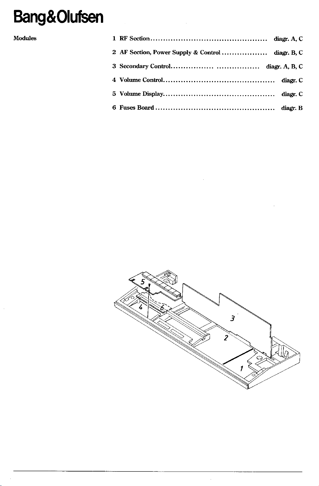
1 RF
Section,,..
....
diagr.
A,
C
2 AF
Sectioru
3 Secondary Control......,......
4 Volurne
5 Volume Display
6 Fuses Board.,
Power
Control
Supply & Control
..,,,.........,...
...
B,
diagf.
A,
diagr.
......
...... diagr. C
....... diagr. B
B, C
diagr.
C
C
Bang&Olufren
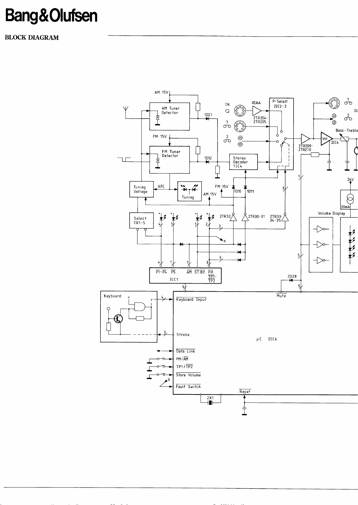
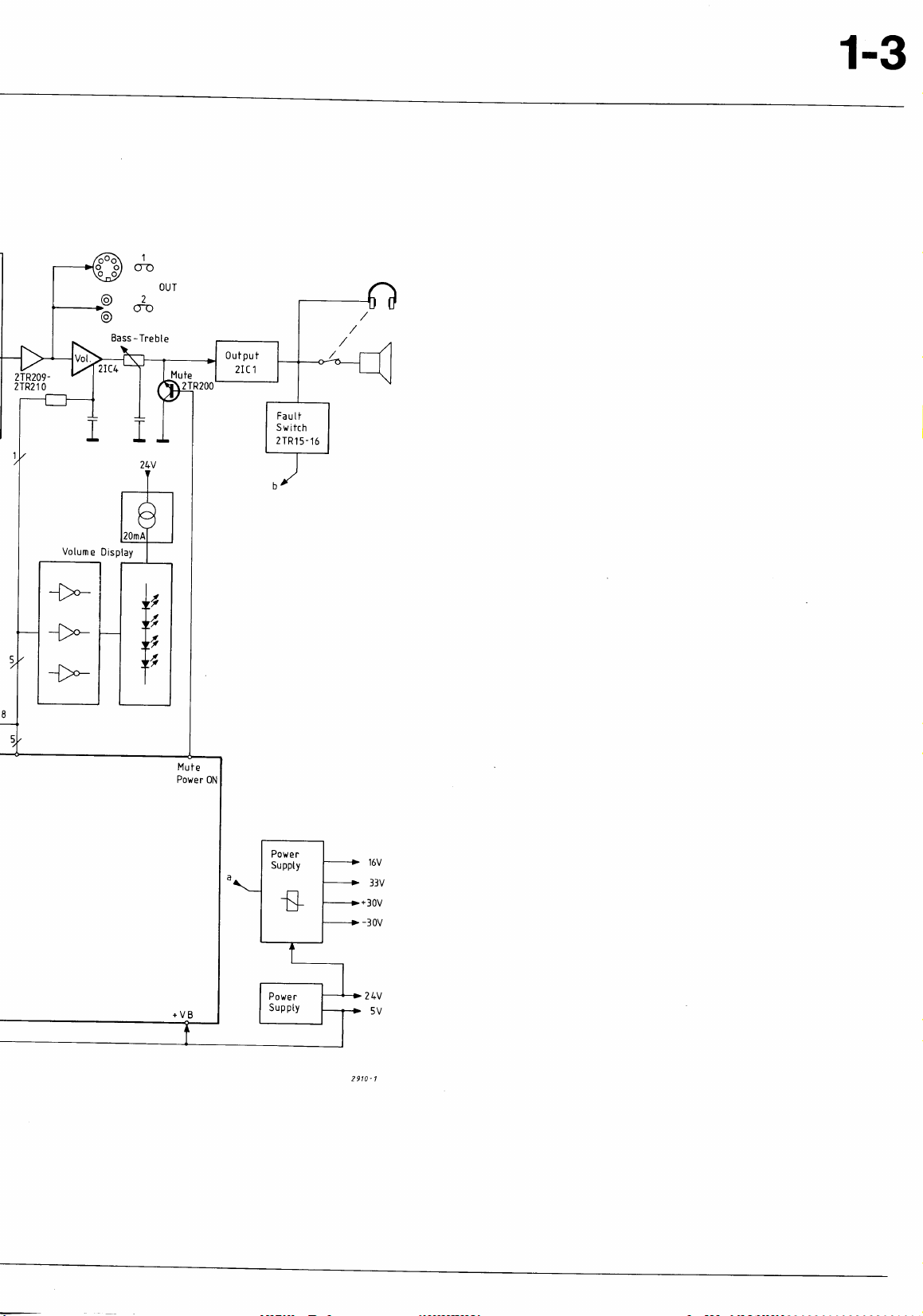
BLOCK
DIAGRAM
Tuning
Vottage
AM
Tuner
De tec to r
FM
Tuner
D etec tor
oo
oo
IN
\,{
P-Setecl
-
2IC2
3
2TR204-
1
L
2TR205
I
24V
Votume
2TR30-31 2TR33-
Disptay
RESo;id-IntlT
R e6et
C 2lC6
I
Mu
->-i
{r
_>_>-
te
+,
+,
lo
2TR2092TR21
0
oo
1-3
1
OUT
Fault
Switch
2TR15-16
Votume
Display
16V
57V
*30V
-30v
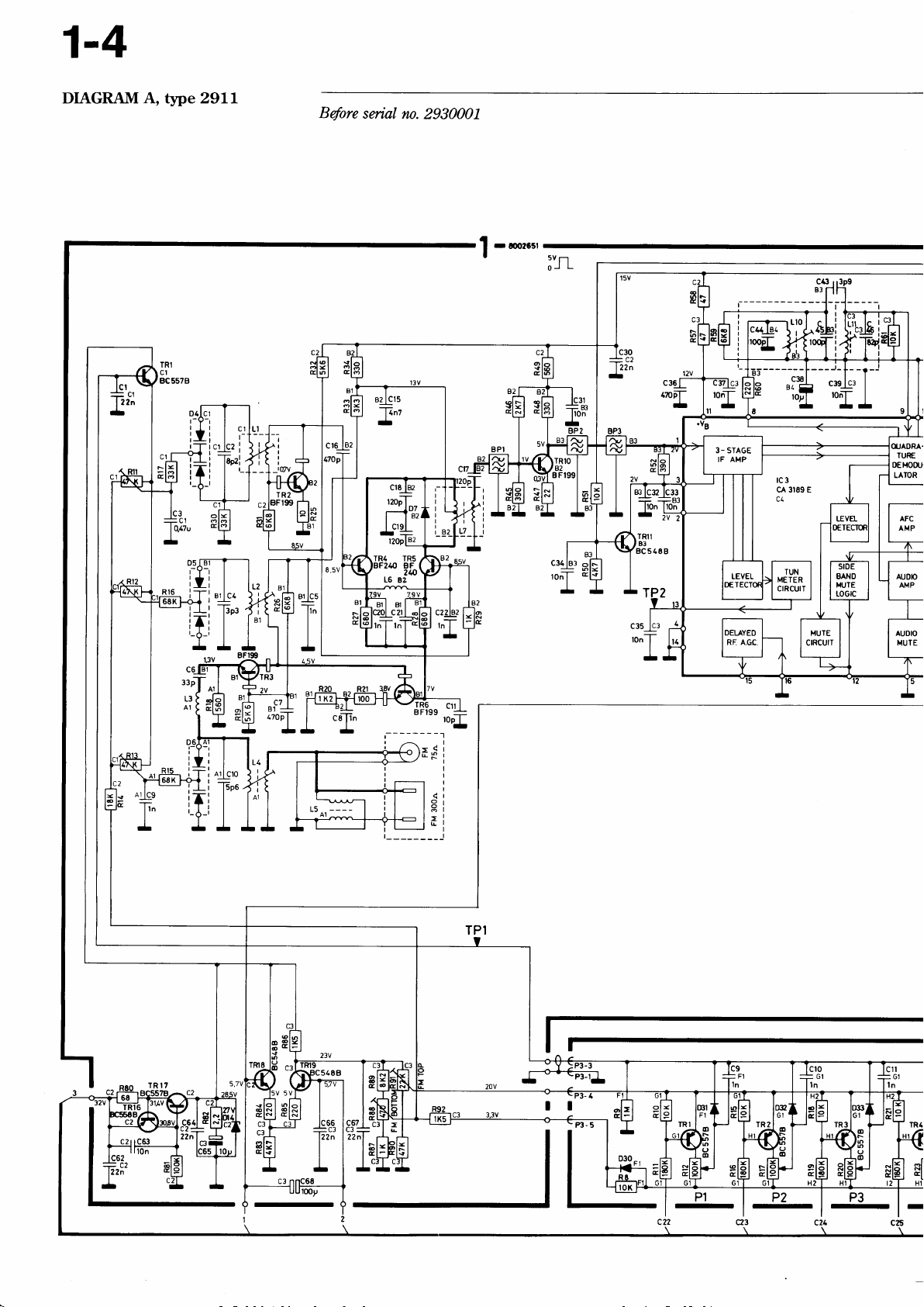
1-4
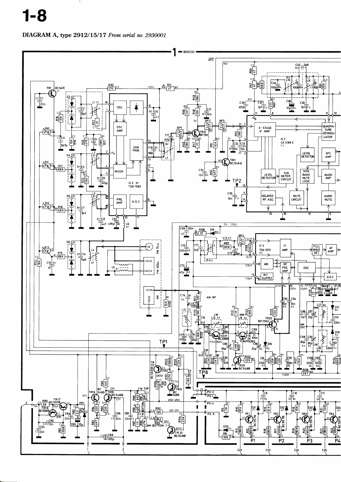
DIAGRAM A, tlpe 29LL
Before
serial rn.
2930001
c34
ronf
rI
l83
B
lc:n
- -bJ
llOn llOn
-fi-
TRlI
B3
BC54AB
?
opT
-
t------
i
-
rc3
cA 3189
c4
Ll0
c38
'.E
loy
Bang&0luben
c43
83r
I
I
I
I
I
r
t.
I
I
-
r-
t-
tt
:rsl
ton-f-
rt
I
E
STEREO
o
l0
zLv
cr20
=Cs
22On
tc?
)J JJ
tc3
=STEREO..AFC
AUTO
=MONO,-AFC
MOt€
B13
c22
-
8r8
-
C30
N
rL
rrV
I
I
cn

Bang&Oluben
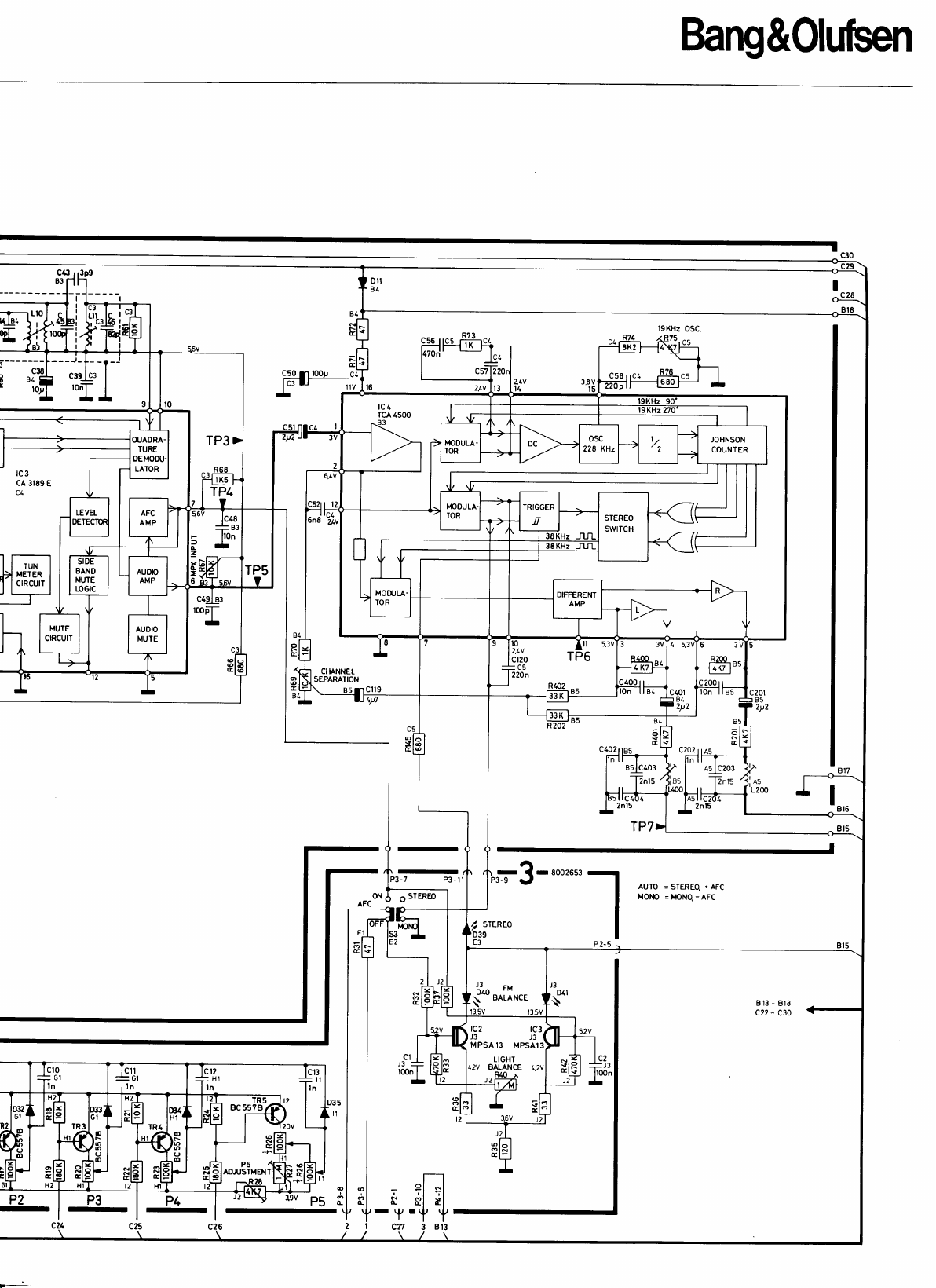
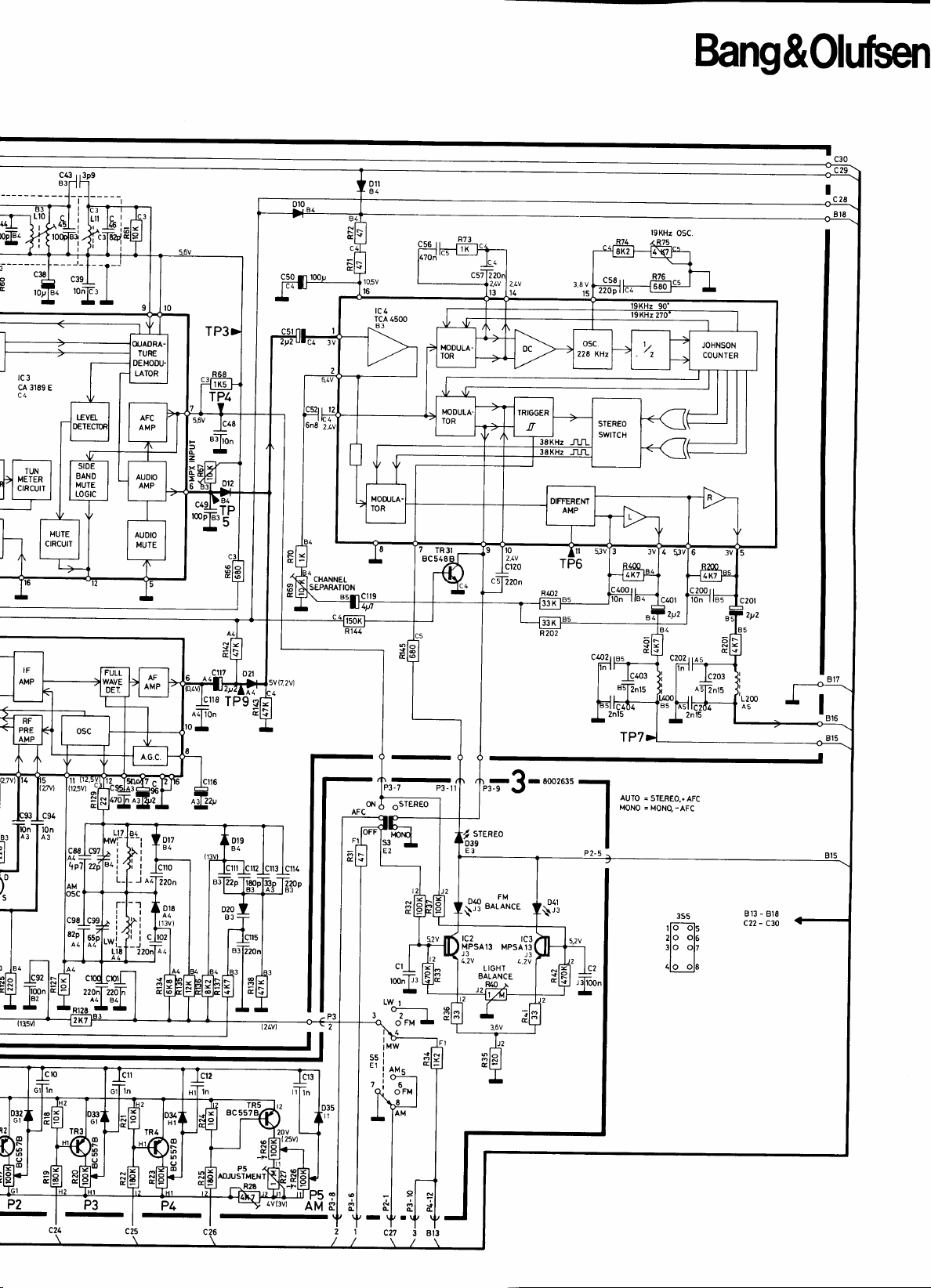
DIAGRAM
A,
type 29L2/L7
cT[izn
-
TRI
BC 547C
Before
cllLl
'i
I L
l_J_'_
serial
rn. 2930001
71O BF
L6 ez2
-
roorrro
|
4o
5v
OJ
Tr
L
cTzzn
*
c3sI
TP2
12v
tonpr
-l
SIDE
BANO
MUTE
LOGIC
'^I'
T
.dT^
-
8F199
---------.1
rf
i t-------
g-r--
|
o
L
TR
20
s(
o
o
(J
ao
c'lr
topT-
-
i
ic6s-
ittdil-*
|
I
(
0v
15v)
I
r.r_al!
r
riz,sur
ol
t
cealo
^rP,
I
r
*I,
T'Irr
oq
220
A'
'cl
R22
cr0
ln
P2
-
P:
-
rc3
cA 3189 E
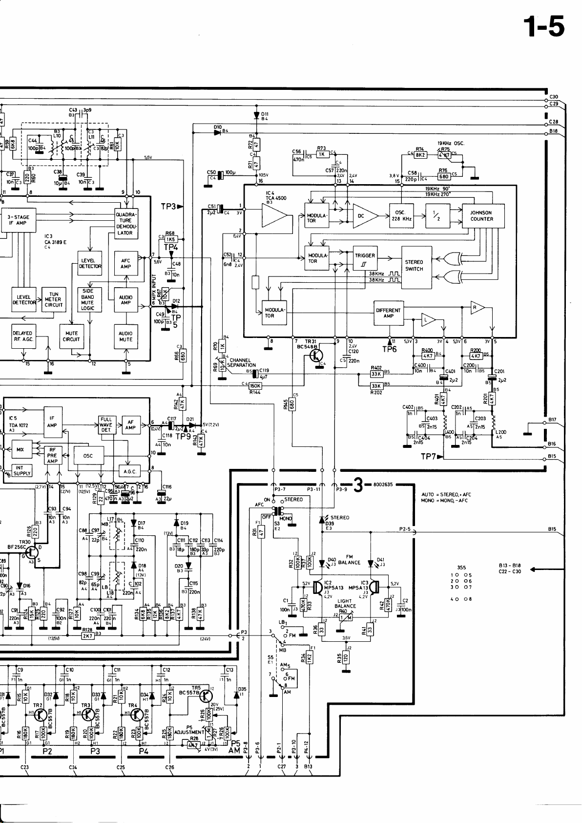
1-5
)31
lh
o
INT
SUPPLY
lioon
lB2
-
_c94
lon
A3
cr2
020
B3
flz
lcr't3 lcil4
tcr3
cl
roonT
-
LBt
L---l
lr
tMB
ssl
E1
i
AM.
l^i
tai
otr"
8
AM
{fl'^Il'.'
rc2
MPSA13 MPSAl3
J3
t,,zv
t
rc3
.2v
=
AUTO
STEREO..AFC
MOt,lO = MONQ
J3
-AFC
o 05
r
O
2
30
40
3Ss
06
07
08
B13 - Bl8
-
C30
c22
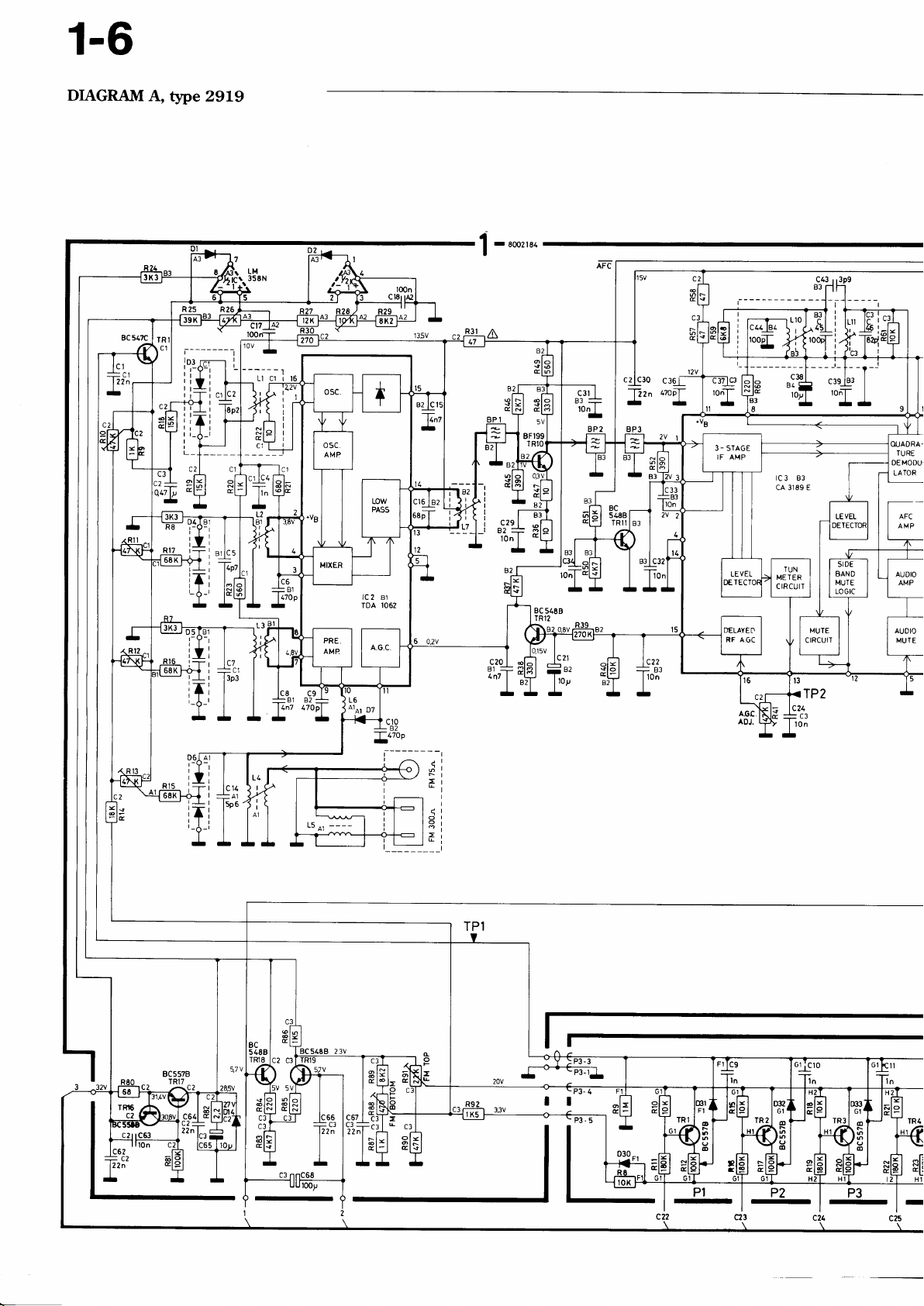
1-6
DIAGRAI|{
A,
t5pe 2919
)_14q1
iIi
t--r
Irj
iTl
'?
-'
-
c43
3p9
f
83T
I
J-
c2 | C30
c36
-pz"
oocT
--
3 - STAGE
IF AMP
rc3
93
cA 3189 E
I
IUN
METER
CIRCUII
OUADRA.
TURE
DEMODU.
LATOR
AFC
AMP
AUOIO
MUIE
ca
lcg
l"
R24
170c1
'l
l1n7
I
I
-
L4
.v
I
A1
AGC,
ADJ.
-
c21
ll0n
I
IP2
TPI
=
F.5Lrt
rca
-i
22nl
Nt.
I
@t'
|
(t'
|
t-
rIr
(
pI
IITIT
P1
P2
-
P3
-
el-
-
Lr0
I
c38
84
l
toy
rc3 83
cA 3189 E
C43
B3
Bang&Oluben
3p9
1 1
c57
l2?0nl | ".o.. ^,
-{
2,av
13 I t4
I
lz,w
3,8vf-;:li---J6s0
15
R76
^r
Fj
IUN
TER
ME
CIRCUIT
c49 I
''T-
-
ln
B3
TP5
9
c3
E
lr02.4v ail
c12o
TP6
53v
c403
1n15
tl,
-r
ol
sl
EL
B4
'
P7)
-
r
rc3
t,zv
8002653
AUTO=
MONO=
.
AFC
STEREO.
MONO.-AFc
813 - Bl8
LII - LJU
,?3
STEREO
o
t2
E
rc
2
MPSA13 MPSAI3
J3 J3
t
,2v
LIGHT BALANCE
lln
-[
ol
EI
?l+l
2l
;
r
-
Y'Y
sldl
Y
3.ev
P2
-
P3
-
Pl*
-
P5
Bang&Oluben
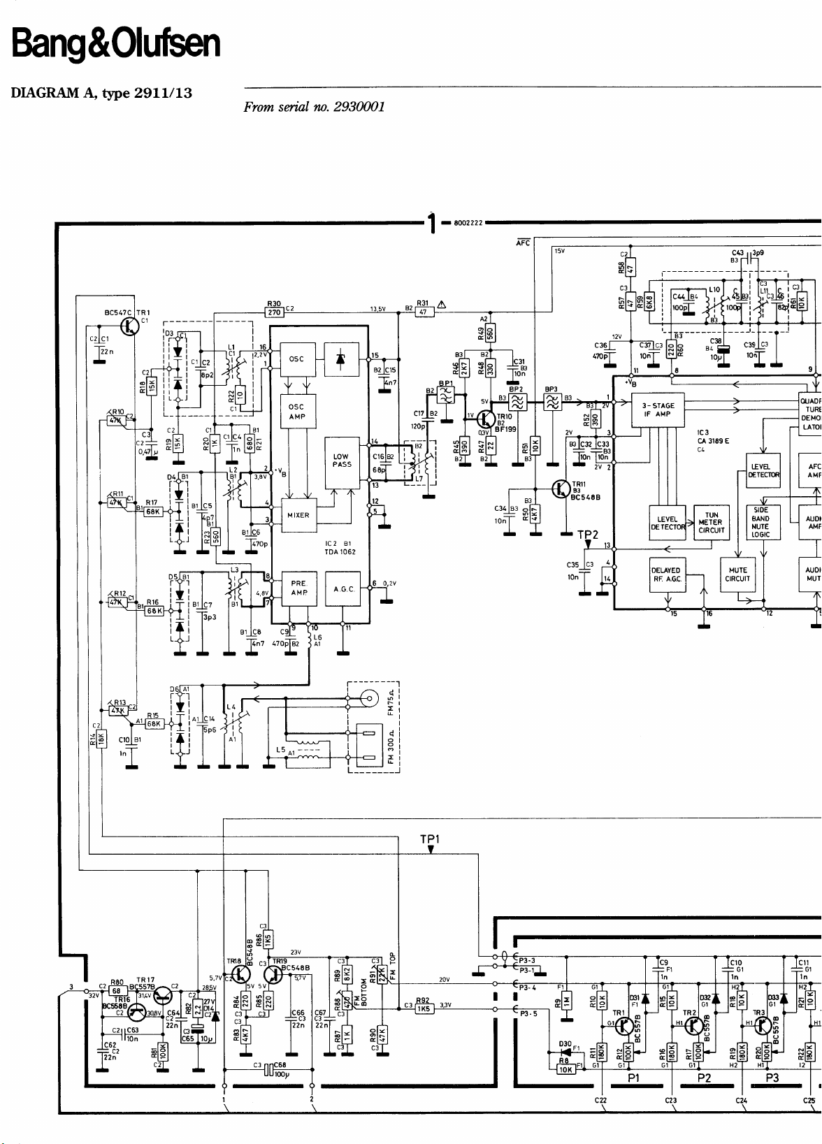
DIAGRAM A, tSpe Z9LL|LS
ir+j I
L_l--___
c+ cl
ar
.)+
o
E
^,.1 ..
-
From
suial
rn. 2930001
|
-roorrn
c43
83r
Pi'
i'l-
rlF
tli
ri
lc2 81
1062
TDA
P1
-
P2
-
P3
t-
STA6E
AMP
rc3
cA
3189 E
C43
EJ
1-7
1s3p9
)ELAYEO
RE AGC.
c9
In
STEREO
o
l0
ztv
cr20
=cs
22On
I
ol
sl
cI
LqUJ
:
2^15'
t1
P7',
=STEREO,.AFC
AUTO
=MONO,-AFC
MOI'{O
-
813
Bl8
-
c22
C30
tcz
i3
MPSA
sl
cI
t2
13
tg3
J3
MPSAI3
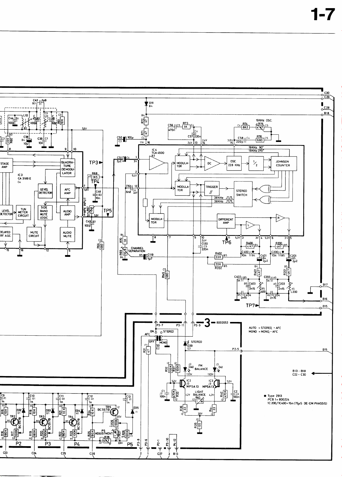
Type
a
2913
=
PCB 1
tC 200/IC4OO=
8002?{'
l5n
(75pS
OE-EM
PHASSTS)
P2
-
r\P
(L
I
cn
1-g
DIAGRAM
A,
tlpe 29L2/L5/L7
BC547C
c1
c3!3
--r-
7yr
lo,o
-
I
o/.
From serial rn.
lc2 B1
1062
T DA
2930001
li
c17
iz
TRIO
r99
,,
B3l10n
'u-r
TRlI
548 B
TP2
c3s
I
'o^I'
ca#4
17o{_
-
,ll
5J
llOn
2
43
B
I
Ti
-?-'
rl
I
LI4
A3
rNr
SUPPLY
R22
P1
-
pEl-ea
-
3
c38
^
F5
-
lov
rc3
cA 3189
E
Bang&Oluben
-l=toon
lBt
-
zzoTzzfi
^4
84l
|
rrli
cl2
"o
020
R?
llTol*f
12tvl
cll4
tl
lCrS
cl
rco;F,
-
Lwl
r?;f.H
lr
rMw
ssi
E1
i
lM.
lr
7i
6
oFM
R
tv-
I IAM
,tfl
roJl"..
AUTO
MONO
=
STEREO..AFC
=MONO-AFC
3S5
rlo
2lo
'lo "l'
clo
o|s
ol5
ole
200
dn
A5
-1
asT
I
I
B13 - Br8
c22 - C30
LlgtLr
E*
Bang&Oluben
il tlpes
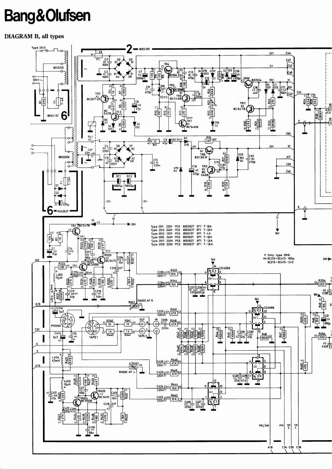
DIAGRAM
B,
c2
81
=
l00n
c3
l00n
TR2
A3
327-25BC
BC
5178
I
)r0
A2
43:
ntl
lg
luz
F2m
I
aa
343
17v
t
lai
D12
6-
8002627
Torp
-
H1
c213
-
-
ooHl
DI
.-H3
| |
+H'l
|
I lssn
r--r
czte
lryl"gl
RADIO
H4
Type
29ll
Type 2912 240v
Type 2913
Type 2915 240v
Type 2917 220V
Type 2919 220v
AF R.
PC6
220v
8002627
PC6
8002627
l20V PC6 80OZl37
PC6 8m2627
PCG 8002627 6Fl
PCO 8002627 6Fl
BDI
:r8
las
22Oy
6Fl T-IFA
6Fl
6Fl
6Fl
?i.\
38W
TRg .
33(
5468
-[
-t:
tt,
T-1,5A
T-44
T-IFA
T-1,64
T-1,6A
t5v
tsJ
c20
:83
17Op
I
I
t
o
type 2919
Onty
oo
5C213.6C413-toop
6C2t5.6C415-
2n2
-
-
c4r6
68n
|
AF L
RAOIO
sa7
c428
ul-
22op
H:
Hl
|
|
22opl
I
-
-
ru/ru
AIE c34
qls
c36
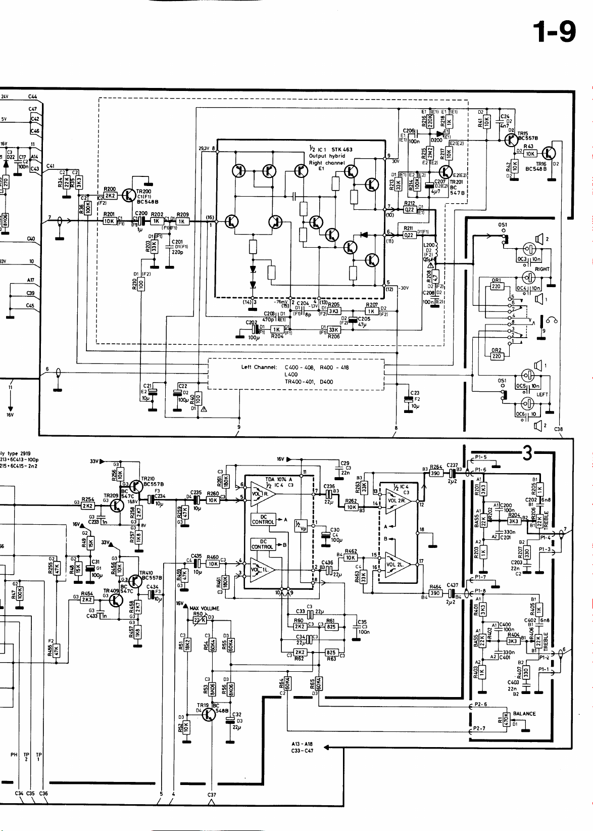
1-9
lrz
srx
rc r
Output hybrid
ael
R43
BC 548 B
IRI6
cn
t0
At7
I
I
ll
I
I
t6v
Letl
Channel:
C400 - 408, R400 - 118
1400
TR400-101,0400
c23
=F2
lo)l
=rl
il-ll
tZ
ltFztl
)8102 |
n
l{Ez)t
Il
__l
('
i
I
I
I
I
.[^
(1
('
.1,
ly
typc
2919
213.
6C413 - t00p
215.6C615-2n2
r,"f-
i
:
sl6l
f*E+-
T,IAX
VOTUME
AI3
c33
r-3
arrr
|
-
Pt-
;2
B2
c403
,,3,7
BALANCE
-
AIE
-
C47
Pt- I
I
c34
C35
C36
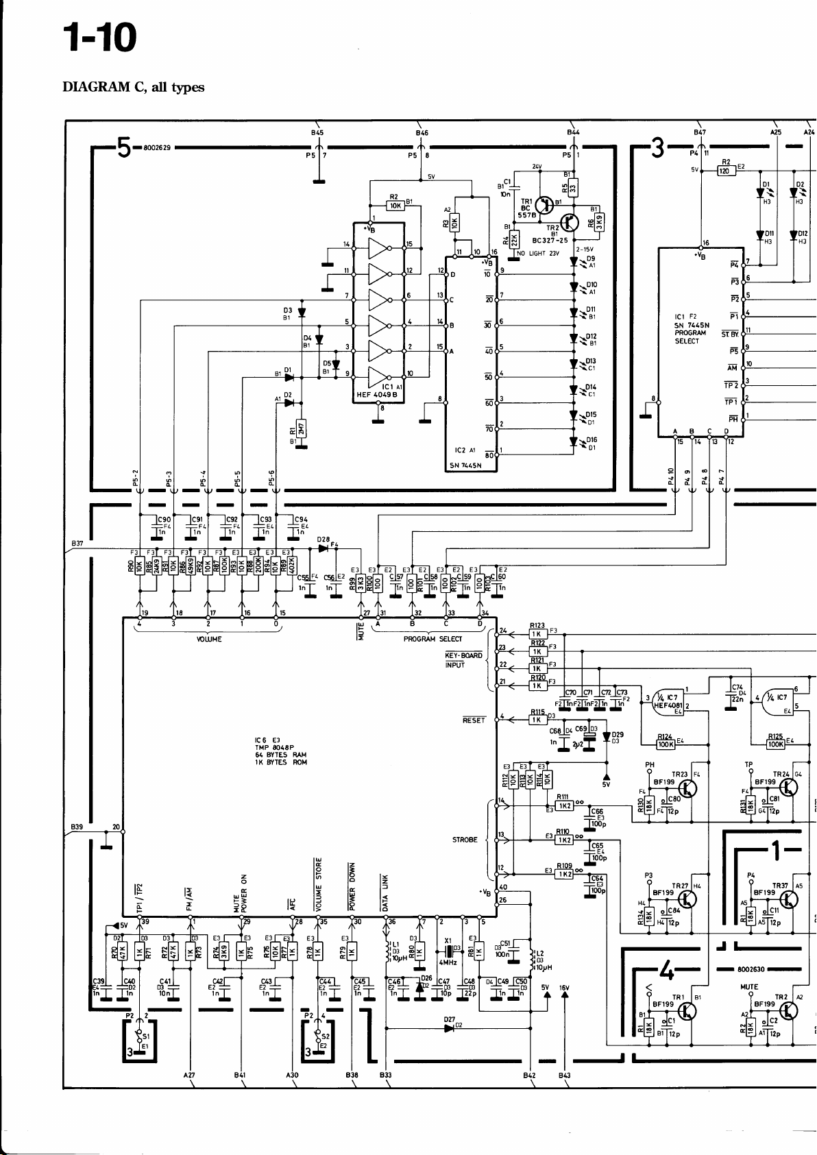
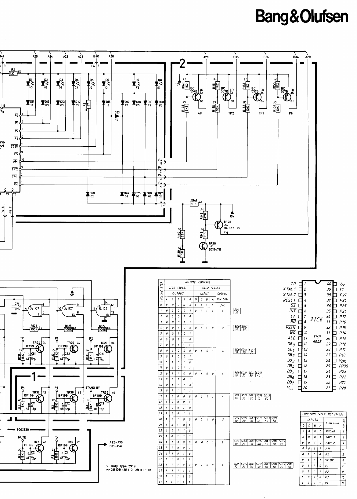
1-10
DIAGRAM
C,
il
t5'pes
eS
lqo
50
lc2 A1
?445N
sN
lt't
5578
'E?\
BC32?
NO LIGHT 23V
A25 421
r
-25
-15V
2
F2
P1
F:t
Fi.
Pt
g!{
Sr
F'5
Iti
Tn
TPI-
FF
\t^l
\oil
\%l
\'J1
\oJl
\oJf
\trti
tct
7445N
sN
PROGRAI,I
SELECT
\Ti
c,i,E
E
II;
2
il
c4l
I
lon
I
-
-
lc6 E3
TMP
64
IK
5F
C/*3
Ea-
ln I
-
8048P
BYTES
RAM
BYTES ROM
rH|3
|
-
t=
lE
l=lSl=
lH
lS
!!,
D3(
oPH'
z6r
il=
iI
;I
l"zl,,-
El
B3E
-
1
B3:I
L2
03
10yH
5V
l6v
rt
lll
lL_
-l-l
843
842
tl
BFI99
BFr99
TR27
A.
TRI
./l
ffi
Jl-
-
E002630
-
Bang&Oluben
15N
,il4
I
P1
tr2
FI
SisY.
p-E
rT
IP2
TPI
FF'
F5
-
-
-T -
I
TR24
BFI99
ffiq
Jt-
-
-
TR3O
43
BC 547 B
al.J
q
s
S
0
0 0 000 7
1 0 0 0
2
0 0 0 0
3 0 0
1
0 0 I 0 0 0
5
0 0 7 0
6 0
7
0 0 I
I 0
9
0 I 0
t0
0
t1
0 0 I
-
-
A30
A22
B3 - 847
0 I 0
0
0 1 0
15
0 I
t6 0
17
18
19
?0
I 0
2l
23
21 I I
1
25
26 1
7 1
28
29
I 1 0 1
1
JO
J1 1 1
VOLUME
(8018)
2rc6
OUfPUT
3 2
0
0 I 0
0 0 0
I
0
1 1 0 1
0 0 0 0011
0 0 0
0
0I0
0 0 1 1
010
0 0
0
0 0 0 0001
0 0 I
0I0
0
CONTROL
0 olc
0
0
7 I
010 o
0
0
0 0100
1
000010
1
0 0 0000
I 0
5I(2
INPUf
aln
(71
0
5)
OUTPUT
PIN LOW4
X
ls-D,
9
t10 |
ItDrls-Dtdl
7
t10t20l
lsD{noTiaTl
1101201301
lslDr$ontson-ilSdOl
5
tt0 t20 tJ0
lsDtlsDqsDTlwqntn
t10t20l30l40ls0l
W
J
lt1l20l30l1olsol60l
W
2
10
20 | 30
|
|
W
1
t10 |
20 | t0 | 40
110 I
/,0
l
TO
7
1
XTAL
XTAL2
RESE T
s
NT
2
3
4
5
6
EA
KU
I
Ps-EF
9
10
w
44
ALE
DBo
12
DBt
t3
DBz
1q
DBr
DBt
16
DBs
DBa
18
DBz
19
/tt
20
FUNCiljN
INPUTS
D
c
0
0 0
0 0
s0
70
60
l
|
|
s0
| 60
l
170 | 80
0 0
|
0
0
I
0
1
0
I
0
|
0
1
0
0
10
JY
38
37
36
35
J4
33
JZ
)1
JO
zv
28
27
26
z5
z4
23
22
2l
\ABLE
3tC1
FUNCflON
B
0 PHONO
0
TAPE
0
|APE 2
AN
0
0 P5
0 7 ST.
0
P1
1
P2 9
0 0 P3
0 I
P1 I
BY
(7115)
1
Vcc
P27
P26
P25
P21
P17
P16
P15
P14
P13
P12
P11
Pt0
voD
PRO6
P23
P22
P21
P20
2
T+
5
6
7
10

Bang&Oluberl
SEI{I{ONDUCTORS
Transistors
1TR1
1TR2-3
1TR4-5
1TR6/10
1TR11-12
'1TR16
1TR17
1TRr8-19
1TR20
1fR21-22
1fR27
832028t 42
A320311
8320281
8320108
8320104
8320152
8320108
8320104
83201OA
8320329
8320377
20
BC 547
20 BC 182
't7
BC
182
BF 199
42
BF 240
42
BF 199
20 BC
20 BC 558
20
20
20 BC
20 BC
20
548 B
BC 557
BC 548
558 B
548 B
BC 338_25
C
C,/CK
CL 2TR6-7
B
B
B
2TR5
2TR8
2TR9
2TR10
2TR11
2TR15
2TR16/19
2rR23-27
2TR30
2TR31
2TR32-35
8320104
8320108
8320241
8320237
8320369
8320097
8320152
8320108
A320281
8320097
8320316
8320152
20
BC 558 B
20 BC
32 BD 138
20 BC 546
31 BD 534
20 BC
20 BC 557
20
42
20
20 AC
20
548 B
547 B
BC 548
BF 199
BC 547 B
327-25
BC 557
W
B
B
B
B
1TR28
1TR29
1TR30
1TR31
lTR3s-37
2TR1
2TR2
2TR3
2rR4
'8320396
8320108
8320535
8320108
8320281
8320097
8320316
8320097
8320369
20 BC
31 BD 534
24
MPF 4392
24
2N 5639
24 2N
20
22 BF
20 BC s48
42
20
20 BC
4392
BC 548
256 C
BF 199
BC 547 B
327_25
547 B
2TR400
2TR401
B
B
2TR404
2TR40A
409
2TR41U
3TR1-5
4TR1-3
5TR 1
sTR2
8320108
8320097
8320405
A320377
A320152
8320281
8320152
8320316
20
BC 548
20 BC
20 BC 5s0
20 BC
20 BC
42
20 BC
20 BC
547 B
547 C
557 B
BF 199
557 B
327-25
B
B

2-1
IC'S
1tc1
1tc2
1lc3
1lc4 8340284
8340569 r03 LM
8340198 101 TDA 1062 2tc7
'8340233
101 CA 3189 E
101 TCA
358
4500
N
1tc5 8340489 r01 TDA 1072
2tc1
2tc2-3 ^8340202
2tc4
8350000 STK 463
102 HEF
102 CD 4066 BCN
102 MC 14066
8340187 ltl TDA 1074 A
4066
a8340543 124 TMP 8048
L8340172 102 CD 4081 BCN
102 HEF 4081 BP
102 MC 14081 BCP
A 3tc 1 8340192 101
10r DM 7445 N
3tc2-3
ST
BP
BCP 101 DM 7445
8340054 19 MPS A13
8340542 101 HEF 4049
8340192 10r
SN
SN
7445
7445 N
N
BP
N
*Specielt
*Specially
*Speziell
udvalgt eller bearbejdet eksemplar.
selected
or adapted sample.
ausgewiihltes und bearbeitetes Exemplar.
ABefder statisk elektricitet kan
Alndicates static electricity may
ABedeutet
ASignifi
statische Elektrizildt die Komponente zerstitren kanrl
que
€lectricit6 statique
odelegge
komponenten
destroy the component
peut
detruire
le
composant

2-2
Diodes 1D1-2 8300058 209 1N 4148 2D15 8300036 209
rN 4r 48 209 BZX
215
217 SFD
1D3-6
107
1Dl0-12 8300058 209 1N 4148 2D17 8300058 209
1D14
'1D15
1D16 8300384 234 KV
1Dr7-19
1D20 8300384 234 KV 1226 Y
1D21 8300058 209 1N
2D1
8300308 222
8300306 209
215
217 SFD
'8340105
8300058 209 1N 4148
8300385 209
209
215
217 SFD 184 209 BZX
2't5
217 SFD 184
184 209 BZX 83 C
BB 204 2D16 8300135 209 ZPD 3.3V
209 BZX 79 C 3.3V
BA 479 209 BZX 83 C 3.3V
1N 4148 215 lN
184 217 SFD 184
ZTK27 SB 2D18-19 8300023 209 1N
1N 4148 2D20 83003 t3 209 ZPD 15V
209 BZX 83 B
1226 Y
2D21-22 A300058 209
BA 423 26-29400 215
217 SFD 144
3D t-4
4148
1N 4148 8330001 cQY
3D5
.8330084
ZPD 4.7V
79 C 4.7V
1N 4148
4148
4002
79 B 15V
1N 4148
1N 4148
LT 9306 D
10-5
cQY 85 t-it\/
4.7V
15V
A
2D2-5
2D6-9 8300294 209 MR 501 3D11-1zY 8300058
2D10-t1 8300023 209 lN 4002 30-35
2D12 8300058 209 1N 4148 3D39-41
2D13
8300023 209
8300201 209
1N 4002
212 1N 5401 16-29 215
lN 4148
215
217 SFD
184 5D1-s 8300058 209 1N 4148
ZPD 6.2V 217 SFD
3D6-8
23-29 217 SFD !84
'8330084
209 1N 4148
'8330126
215
209 Bzx 79 c 6.2V
'8330084
2D14
209 BZX 83 C 6.2V 5D9-16
8300058 209 1N 4148
1N 4148
215
217 SFD I84
6D1-2 8300023 209
LT 9306 D
1N 4148
LT
9306 E GA
1N 4148
184
LT
1N 4002
9306
D A
A

Bang&Oluben
3-1
IIST OF ELECTRICAL
2919 only
-
FCB I
RF, IF & Stereo Decoder
From seria.l ,0. 2934n1
8(n2222
8002223
8(n2224
8AO21U
2911
We
2912/15/17
M6
2913
We
2919
We
PARTS
Rnistors ,nt nentioned
0cl
0c2
0sr
0c3
0c4
0c5
0c6
4200540
4200540 6800
7400254 Svritch SPEAKERS
4010041 10
4010041 l0 nF
4010041 10
4010041
cr 4010060
c2
4000106
c3 4200476
c4
4010027
c5 4000104
c6
4010087
c7 4000099
c8
c9
4010063
4010087
c10. 4010027
c14
4000105
c15 4010063
c16
4000107
ct7. 4000170
c31
c32
c33
c34
4010041
4010041
4010041
4010041
c35 4010041
c36 4010087
c37
4010041
c38 420043r
c39
4010041
c43 4000082
c44
c45
c46
c48
4000085
4000085
4000110
4010041
c49 4000085
c50
4200129
c51 4200423
c52
4130050
c56 4130293
c57 4130215
c58
c62
c63
4101007
4010060
4010041
c64 4010060
c65
c66
c67
4200487
4010060
4010060
c68 4200493
c69 4130215
c70 4130215
c71
4100216
c72 4000109
6800
nF
nF
10 nF
22 iF
pF
8.2
0.47
1 nF
4.7
470
3.3
4.7 nF 100/0 63V
470
1 nF r0% 63v
5.6
4.7 nF 10S'o 63V
pF
68
120
10 nF
10 nF
nF
10
10 nF
10 nF
470
nF
10
pF
r0
10 nF
3.9
100
100
pF
82
l0 nF
100
r00
2.2
6.8 nF 1@,6
0.47
0.22
220
22 nF
10 nF
22 nF
10
22 nF
22
100
0.22
o.22
3.9 nF 2.5%
56
are standard. 5%t, 1/4W
pF
40V
pF
40V
-2Gi80Vo
-2Gf80Vo
-2&l-8@/o
-2Gl-80ry0
-20*8U/o
0.25
50V
!F
100/0 63V
pF
0.25
pF
100/0 63V
pF
0.25
pF
l0o/o 63V
pF
0.25
63V
2qo
pF
2% 63v
-2Gf80Yo
-2GF80Y0
-2Gf8@/6
-2cl-80s6
-2Gf80s'o
pF
1@/o 63V
-20+80%
l6v
-2Gf80o
pF
0.25
pF
20,6 63V
pF
29o 63V
sqo 63V
-2Gf80o/o
pF
290 63V
pF
16v
yF
50\
pF
l0o/o 63V
2@/o 63\
1tF
pF
5vo 63V
-2Gf80o/o
-20+800,4
-20'110U/o
50V
!F
-2Gf100%
-zO+lD0ok
nP
pF
10V bip.
yF
200/0 63V
20Vo 63v
1tF
pF
2olo 63V
pF
pF
pF
pF
pF
250V
63v
40V
40V
40V
40V
40\
250V
63v
63V
63V
40V
40V
40V
40V
40V
40V
40v
63V
40V
40V
40V
0Rl
0R2
2 0Tr 8013308
c73 4200483
c74
c75 4000170
c76
c77 4000085
c78
c79 4130179
c80
c81
c82 4100216
c83
c88
c89
c90
cgr
c92
c93 4010041
c94
c95 4130293
c96
c97
c98 4000110
c99
c100 4130215
c101 4130215
cr02
c110 4130215
c111
c111
c112
cl13
cr14 4101007
c115
c1t6
c117
4O\
clt8
c119 4200477
40V
40V
ct20
c400.
c40l 4200423
c402 4100019
c403 4100081
c404
carbon
film.
5001019
5001019 220
8013310
4100019
4010061
4000170
4130179
4100033
4340003
4000218
4130179
4340002
4130215
4130179
4010041
4200423
4340002
4340003
4130215
4000159
4000026
4100108
4003125
4130215
4200480
4200423
4130220
4130215
4130220
4100081
220 a lCP/o 12w
A 1U/o 1'2W
Mainstransformer
29tUt2/15/17
Mainstransformer
/19
29r3
pF
47
16v
I nF 2.5q0 63V
pF
120
2% 63V
nF 10% 63V
2.2
pF
100
2olo 63V
pF
2ok 63Y
120
pF
0.1
20vo 63v
pF
20qo
nF 590 63V
pF
foil
pF
5qo 63V
pF
200/o 63V
pF
foil
yF
2@/o 63Y
yF
20oi6
-2G18090
-2Gl-80q0
pF
1@i6 63V
pF
50V
pF
loil
pF
5% 63v
pF
foil
pF
zook
pF
200/0 63\
pF
2(M 63\
pF
2% 63V
-
460 kHz)
pF
63Y
2o/o
-
455 kHz)
pF
5%
pF
2% 63V
pF
5qo ffiV
yF
20c/! 63\
lov
ItF
50Y
vF
pF
25Y
pF
2U/o
50v
ttF
nF 2.5q0 63V
63V
63V
63V
40V
40V
63Y
63'\l
63V
63tl
63V
0.1
3.3
3.9 nF 2.5%
5.5-65
4.7
0.1
2-22
0.22
0.1
10 nF
10 nF
0.47
2.2
2-22
82
5.5-65
0.22
O.22
0.22 uF 20vb
0.22
18
(IF
22
(lF
180
33
220
0.22
22
2.2
l0 nF 59o 63V
4.7
0.22
10 nF 5% 63V
2.2
1 nF 2.5V0 63V
2.r5 nF 2.5q0
2.15
R10
R1l
R12
R13
R31
R57
R58
R67
R69
5370061 47
5370061 47 ld) 2Uk
5370061 47
5370061
5020345
5011009 47 A 5r/o
5011009
5370074
5370074 10
l& 20o/o
ld) 2U/o
47 ld) 2UYo
47 Q ltY/o Y4W
47 A 5% L2W
10 l(1 20%
K) 20qo
1,2W
R71 5011009
R72
R75 5370058
R88 5370150
Rgr 5370068
R93
Rl00 5370074
R106 5020148
R120 5011071
5011009
5370058
47 Q 5o/o 1,2W
\Vo \,2W
47 Q
4.7 1& 2U/o
470 Q 2U/o
22 ld) 2@k
lA 2Wo
4.7
l0 kO 20Vo
22 Q l$/o
1.5 MQ 590 1,4W
Y4W

3-2
Bang&Oluben
2913 onJy*
2919 ottly*
Rt23 5011071
R145
L1
L2
L3
L4
L5
L6
L7
L10
L11
BPr* 8030014
BPz
BP3 8030014
5011024 680
8020322
8020321 RF - FM
4020320
8020319 RF - FM
8020341
6850127 1.2
8020323 IF
8020368 DeL - FM
8020369 Det
8030014 10.7 MHz
c400 4130301
c10
c1l
c12
c13
cr8
c20
4010087
4000178 12
4000178
4000178 12
4130179
4130179 0.1
4010063 4.7 nF 10olo
1.5 MQ 5% 1/2W
0 5% 1,2W
Osc. - FM
RF-FM
Aerialtransformer
VH
-
FM
-
FM
10.7 MHz
10.7 MHz
15 nF l0o/o 63V
470pF l0qo 63V
pF
590 63V
pF
l2
5o/o 63V
pF
590 63V
0.1
200/0 63V
!F
gF
2090 63V
63V
R400
R401 5010726 4.7 l0 2o/o 1"/4W
Lt2.
L13 8020418
L14
L15 a0204t4
L16
L17 AO20417
L18
L400 ao20142
BP4
BP4 8030056 455 kHz
c2l
c22
c24
c29
c30
c53
c54
5010726 4.7 lO 2o/o V4W
8020471,
8020502
8020416
8020415
8030025 460 kHz
4200431 10
4010041 10 nF
4010041 10 nF
4010041 10 nF
4010060 22 tF
4010087 470pF
4010031 680
Tmp 461
IF' , AM
lmH
RF-LW
RF.MW
Osc. - MW
Osc. - Lw
31 mH
kHz
16V
!F
-2Gl80o/o
-2cf8@/o
-2G18@/o
'2M8@/o
100/o 63V
pF
100/0 63V
40V
40V
40V
40Y
PCB
1
Before
serial M. 293Ut01
R26
R28
R41
c1
c2
C6
C7
C8
C9
c10
c1l
c16
cl7
c18
cl9
c20
c2l
c22
c30
c31
c32
c33
c34
c35
c36
c37
c38
c39
c43
c44
c45
c46
c48
c49
c50
c5l
c52
c56
5370061 47 1d) 200/0
5370074
5370201 47 ld) 2U/o
4010060
4000106
4130293 0.47
4000099
4010027 1 nF 100/o
4003125
4010087 470
4010027 1 nF
4010027
4000105
4000016
4010063 4.7
4010087
4000170 120
4000170 120
4000170
4010027 1 nF
4010027
4010027 1 nF
4010060
4010041 10 nF
4010041
4010041 10 DF
4010041
4010041 10 nF
4010087
4010041
4200431
4010041
4000082
4000085
4000085 100
4000110
4010041 10 nF
4000085
42001.29 100
4200423 2.2
4130050
4130293
10 kQ 20qo
-20*80qa
22 nF
pF
8.2
0.25
pF
10qo
pF
3.3
0.25
63V
pF
33
290 63V
pF
10%
l@o 63V
1 nF 10qo 63V
pF
5.6
0.25
pF
l0
2qo 63V
nF 10olo 63V
pF
470
100/0 63V
pF
2olo 63V
pF
2o/a
pF
120
2olo 63V
100/0 63V
1 nF l0qo 63V
100/0 63V
-2O*8@/o
22 nF
-2Gl80o/o
-2&f80Eo
l0 nF
-20+800/0
-2cf80qo
l0 nF
-20+800/0
pF
470
100/o 63V
-2Gl-800/o
10 nF
pF
10
16V
-2GF800/o
10 nF
pF
3.9
0.25
pF
100
290 63V
pF
2olo
pF
82
5Vo 63\'
-20+80q0
pF
100
2olo 63V
16V
FF
pF
50V
6.8 nF 10qo 250V
pF
0.47
r09o 63V
pF
63V
pF
63V
pF
63Y
pF
63V
40Y
250V
63V
63V
40\
40V
40V
40V
40V
40V
40V
40V
63V
40V
Ll2
BP1
c57 4130215
c58 4101007
c62 4010060
c63 4010041
c64 4010060
c65 4200487
c66 4010060
c67 4010060
c68 4200493
c69 4130215
c70 4130215
c71 4100216
c72 4000109
c73 4200483
c74 4100019
c75 4000170
c76 4010061
c77 4000085
c78 4000170
c79
c80 4130179
c81 4100033
c82 4100216
c83
c88 4000218
c89 4130179
c90 4340002
c91 4130215
c92 4130179
c93 4010041
c94 4010041
c95 4130293
c96 4200423
c97 4340002
c98 4000110
c99 4340003
cl00 41.30215
ct01 4130215
cl02 4130215
8020413 l mH
8030037 10.7 MHz
4130179
4340003
0.22
20vo 63Y
1tF
pF
220
5o/o 63Y
-20I80o/o
22 nF
-2Gf80o/o
10 nF
-20+80V0
22 tiF
pF
10
50V
-2t+80a/a
22 tiF
-2O+804/a
22 nF
100
10V bip.
!F
pF
0.22
20o/o 63Y
0.22
20o/o 63V
tF
3.9 nF 2.50/0
pF
56
pF
47
I nF 2,5E0 63V
120
2.2 nF 100/o 63Y
100
120
0.1
0.1
3.3 nF 5olo 63V
3.9 nF 2.5q0 63V
5.5-65
pF
10
0.1
2-22
0.22
0.1
10 nF
10 nF
0.47
2.2
2-22
pF
82
5.5-65
0.22
0.22
0.22
2olo 63V
16V
pF
2Vo 63V
pF
2qo 63V
pF
2o/o 63Y
pF
20Eo 63V
pF
200lo 63V
pF
foil
5olo 63V
pF
200/o 63V
pF
foil
pF
z$/o 63Y
yF
20vo 63V
-2Gf80o/o
-2Gl-800/o
pF
10olo 63V
50V
!F
pF
foil
5Vo 63V
pF
foil
20o/o
tlF
pF
20Vo 63\
204/o 63Y
1tF
63V
63V
40V
40V
40V
40lr'
40Y
40V
40V

Bang&Oluben
3-3
cr10
cl1l 4000159
c111 4000026
c1L2
cl13 4003125
c114
c1l5 4130215
c116
R11
R12
Rr3
R57
R58
R67
R69
R71
R72
L\
L2
L3
L4
L5
L6
L7
L10
L11
4130215
4100108
4101007
4200480
5370061 47 kn 2U/o
5370061 47 kQ 2@/o
5370061
5011009 47 Q 5o/o l,2W
5011009 47 A 5a/o 1.r2W
5370074 t0ld) 200k
5370074 10 K) 200lo
5011009 47 A 5o/o 1,2W
5011009 47 a 5o/o 1,2W
a020322 Osc. - FM
8020467 RF-FM
6850127 1.2
8020319
8020341 Aerialtransformer
8020342 10
8020468 IF - FM
8020368 FM der I
8020369 FM det II
O.22
2U/o 63Y
1tF
pF
18
2olo 63V
-
(IF
460 kHz)
pF
22
ZVo 63Y
-
455 kHz)
0F
pF
180
5qo 63V
pF
33
290 63V
pF
220
5olo 63V
0.22
2@/o 63\
1tF
pF
22
10V
47 kQ 2U/o
pH
RF - FM
pH
ct17 4200423
c118 4130220
c119 4200477
c120 4130215
c400
4L30220
c40l 4200423
c402 4100019
c403 4100081
c404 410008r
R75 5370058
R88 5370150
R91 5370068
R93 53?0058
Rl00 537007
Rl06 5020148
R120 5011071
R123 5011071
R145 5011024
L12 a020471
L13 8020418
L14 8020413
L15 80204L4
Lr6 8020416
Lt7
L18 8020415
r-400
4
8020417
8020142
2.2
sOV
1tF
10 nF 5qo 63V
4.7
25V
FF
pF
0.22
20vo 63Y
10 nF
5Vo 63V
pF
2.2
50V
1 nF 2.50/o 63V
2.15 nF 2.50/0 63V
2.15 nF 2.5V0 63V
4.7 ld) ztwo
470 a 2U/o
22 ld) 2U/o
4.7 ld) 2@/o
10 W) 2U/o
22 Q |U/o V4W
1.5 Ma 5olo 12w
1.5 MO 5olo l,zw
680 a 5o/o 12w
Trap 461 L'Hz
IF-AM
lmH
RF-LW
RF. MW
-
MW
Osc.
Osc - LW
31 mH
PCB 2
-
8OO2l87
Supply & Control
AF, Power
BPT
BP2
BP3
8030014 10.7 MHz
8030014
8030014 10.7 MHz
10.7 MHz
FE 6710001 Fe-beads
c1
c2
c3
c4
c5
c6
C7
c8
cl0
c11
c12
c13
c14
c15
c16
c17
o18
c19
c20
c21
c22
c23
c24
c25
c26
c29
c30
c31
c32
c33
c34
c39
c40
c4l
4201081
4130103
4130103
4130082
4130082
4200L28
4200406
4010024
420027L
4010024
4010024
4200426
4130082
4010027
4010027
4010063
4130179
4200859
4000173
4010024
4201081
4201082
420r081
4010063
4010076
4200478
4010076
4200403
4200129
4200480
4200518
4200518
4130179
4010027
4010027
4010027
pF
10
0.1
!F
pF
0.1
yF
0.22
0.22
trF
47
!F
pF
2200
pF
470
47
!F
pF
470
pF
470
pF
I
50V
0.22
1tF
1 nF 10qo 63V
I nF 10o/o
4.7 nF 100/0 63V
pF
0.1
pF
220
pF
47
pF
470
10
sF
pF
100
r0
!F
4.7 nF 109o 63V
22 iF
pF
100
22 nF
100
!F
pF
100
pF
22
pF
22
pF
22
pF
0.1
I nF l0olo 63V
I nF l0o/o 63V
I nF l@/o 63V
63V
20Dlo 250V
20olo 250V
20o/o 250Y
200/0 250Y
l6v
40V
100/0 63V
63V
10qo
63V
100/0 63V
250\
2U/o
63V
20olo 63V
63V
5olo 63V
l0o/o 63V
63v
40V
63v
-20+100o/o
10V
-2Gl-l00qo
25V
16V
10V
16V bip.
16V bip.
20qo 63V
40Y
40V
BP4 8030025
BP4
c42 4010027
c43
c44 4010027
c45
c46 4010027
c47
c48 4000185
c49 4010027
c50 4010027
c51 4130103
c55 4010027
c56
c57 4010027
c58 4010027
c59 4010027
c60 4010027
c64 4003128
c65 4003128
c66 4003128
c68 4010027
c69
c70 4010027
c7t
c72 4010027
c73 4010027
c74 4010076
c90 4010027
c91
c92 401.0027
c93 4010027
c94 4010027
c400 4200426
c40l 4000018
c402 4200478
c403 4010024
c404
8030056
4010027
4010027
4000175
4010027
4200423
4010027
4010027
4000015
460 kIIz
455 kHz
nF 100/o 63V
nF 100/o 63V
nF r0o/o 63V
nF 10o/o 63V
nF l0o/o 63V
pF
10
5olo 63V
pF
22
59o 63V
I nF 10'/o 63V
I nF l0olo 63V
0.1
20olo 250V
,I)
nl l@/o 63V
nF 1@/o 63V
nF r0qo 63V
nF 100/o 63V
nF 10Vo 63V
nF 100/o 63V
pF
100
sqo 63V
pF
100
5olo 63V
pF
100
5olo 63V
1 nF 1090 63V
pF
2.2
50Y
nF 10qo 63V
nF 100/0 63V
nF 100/o 63V
nF 10qo 63V
-2Gfl00o/o
22 nF
nF 100/o 63V
nF 100/0 63V
10o/o 63V
oF
nF l09o 63V
nF l@/o 63V
pF
50V
pF
SVo
220
100
470
8.2
pF
pF
pF
63V
10V
1@/o 63V
pF
0.25
40V
63V

3-4
Bang&Oluben
c405 42010a7
c406 4130179
c407 4200477
c408 4130103
c413 4000173
c4t4 4200423
c415 4000018
c4l6 4130264
c4t7 4000197
c418 4010065
c419 4130213
c423 4130233
Rl1
R20
R21
R23
R31
R32
R40
R50
R51
R52
R53
R54
R55
R56
R61
5020136 10 O loryo Y4W
5010110 10lo 1%
5020116 7.87 K) 10k v4W
5370058 4.7 t& zvk
5020145 8.661& 1Vo V4W
5020340 8.06Id) 1% V4W
5020159 100 c) 10% 1/4w
5370068 22ld) 2@k
5020235 18.2 W 1% v4W
5010110 10 t() 1% r./4w
5020340 8.06 t() 1% v4W
5020097 60.4I(J 190 l.z4W
5020097 60.4 t(] 1% v4W
5020340 8.061(] 190 1.24w
5020185 825 0
47
40V
uF
0.1
2Crolo 63V
!F
4.7
25Y
VF
0.1
2@/o 250V
!F
pF
47
5% 63V
yF
2.2
50V
pF
220
5% 63v
68 nF l0q6 63V
pF
68
5% 63V
2.7 nF 1096 63V
10 nF 10o/t
0.22
200 63Y
tF
p6 y4W
63V
y4w
c424 4130233
c425 4130233
c426 4130233
c427 4010021
c428 4010021
c429 4000173
c430 4000173
c433 4010027
c434 4200487
c435 42004a4
c436 4200518
c437 4200423
R63 5020185
R64 5020097
R65 5020097
R85 5020240
R86
R87 5020263
R88
R89 5020281
R408 5020657
R4r1 5102016
R412 5102016
R431 5020s95
R432 5020019
R442 5370128
5020140
5020456
pF
O.22
20qb 63V
0.22
20o/o 63v
1tF
pF
0.22
200 63V
pF
220
10Eo 63V
pF
220
l$/o 63Y
pF
47
Sqo 63v
pF
47
5% 63V
1 nF l0o/o 63V
10
50V
!F
10
25V
!F
22
16V bip.
FF
pF
2.2
50V
825 Q 1.0/o Y4W
lo
60.4
lqo V4W
60.4 l<) lqo Y4W
24.9 hO lo/o L/AW
49.9 ld) lo/o Y4W
100 K) rVo V4w
2O0 ld) lo/o Y4W
402 ld, lqo l4W
4.7 A lu/o 1nW
0.22 O 1090 1w
0.22 O |U/o \W
249 W) lVo 1/4W
36.5 I() 1% v4W
r00 l() 20qo
2919 only
PCB
3 - Secondary Control
8002653 FM
8N2635 FM.AM
L1
L2
c27
c80
c81
c82
L403
L404
c1
C2
c9
c10
c1l
c12
R1
R2
R12
R17
R20
R23
6600009 2 A-T250v
8020342 10
8020342 10
8090003 4 MHz
4010060 22 nF-2O*aU/o 40!
4000178 12
4000178 12
4000178
8020342 10
12
FH
pH
pF
pF
pF
yH
SrEC 127
5Eo 63v
5% 63V
5% 63v
aO2O476 4.7 mH
4\30224
4130224
4010027
4010027
4010027
4010027
5300123 470 16l lin
5011014 120 a
5300092 100 l(l
5300092
5300092 100 K)
5300092 100 I(l
pF
0.1
100,4 63V
pF
0.1
10vo 63v
nF 1096 63V
nF 10% 63V
nF 10o/o 63V
nF 10o/o 63V
SVo
preset
preset
100
lO
preset
preset
1/2W
RLl 7600069 24I/
6850114 0.5
c83 4000178
c84 4000178
c413 4000173
c415 4010061
c13
c400
c401
c402
c403
R26 5320023
R27 5370049
R28 5370058
R40
R402 5310113
R406 5310113
4010027 I nF l@/o 63V
4130224 0.1
4130227 0.33
4130050 6.8 nF 10Vo 250v
4130216 22 nF 10% 63V
5370049
12
12
100
2.2
2x100 ld) tuning
1 MO 20%
4.7 ld) 2@/o
1 MO 20%
2fl2 W)
2fl21&
pH
pF
sqo 63V
pF
5% 63V
pF
sEo 63V
nF 10qo 63V
pF
100/0
63V
pF
100,6 63V
los.
los.
PCB4-800263OVolume
Control
2919 ottly
P1
P2
P3
P4
C2
c3
?220168 8
7220247 7
7220177 1l
7220199 12
4000178 12
4000178 12
4000178 12
pins
pins
pins
pins
pF
pF
pF
5% 63V
5olo 63V
5% 63V
S2
S3
7400200 TP vrP 2
7400271 STORE
7400200 AtrTo
,toNo
7400199 LWA4W,fM

Bang&Oluben
3-5
PCB 5
Display
PCB
PCB6
2913 onl,t
.
6 - 8002627
-
8002629 Volume
Fuses
8002137
Fuses Board
cl 4010041 10 nF
P5 7220168 8
Board cl 4200143 420
F\ 6600022 1.6 A-T250v S IEC127
Rl 5020319 3.3 Ma lqo 1/2w
Fl 6600052 4 A-T
pins
-2GF80o,6
pF
6.3v
40v

4-1
Bang&Olufsen
N
u.^
--&e
tv
w

Bang&Oluben
MEKANISK
LIST
MECHAMCAL
OF
STYKLISTE
PARTS
0lModul 8002222
o2Modul 8002187
03Modul8002653 PCB - Sekun&er betjening
0301
0302
0304
0305
0306
0307
0308
8002223
4002224
8002184
7210416
7500177
2568793
2819157
3170001
3170212
3302378
3302379
3358188
2816195
7219038
7210414
7500177
7500002
8002635 PCB - Sekunder betj.
2548118 Vinlel
2810074 Fjeder
2794061 Skalahjul
3190061
2905066 Leje
2548119 Vinkel
2794000 Hjul 3R26
2395044 LAsering ?hjul
2395035 Lasering
3152383 Holder /LED'S
3152390 Hus 3S2
2812081 Fjeder 3S2
3955034 Skalasnor
PCB - FM 291I
PCB - FM-AM 2912115/17
PCB - FM 2913
PCB - FM 2919
Antennestikdasepanel
Kontakstift
PCB - LF og spendingsforsyning
Koleplade 2ICl
Fjeder
2TR4
Glimmerskive zTR4
I
solationsstykle 2ICo
Sk;erm ovre 2lC6
nedre
Skarm
Koleplade 2TRl0
Fjeder 2TR10
Sdkdesepanel
Stikdese 7-pol. PH/TP1
Kontakstift
Sikringsholder
2911/13/19
2912115/17
Viser
2IC6
TP2
(FM)
(FM-AM)
PCB , FM 291I
PCB - F]|'I-AM 2912/15/17
PCB - FM 2913
PCB - FM 2919
Aerial socket
Contact
PCB - AF and
Heat sink 2IC1
Sprins 2TR4
Mica sheet 2TR4
Insulator 2IC6
Screen upper 2IC6
Screen
Heat sink 2TR10
Spring 2TR10
Socket
Socket 7-pol. PH/TPI
Contact
Holder fltuse
PCB - Secondary control
2911/13/19
PCB - Secondary control 2912/15/17
(FM-AM)
Bracket
Spring
Dial
drive
pointer
Dial
Bearing
Bracket
Wheel 3R26
Locking ring twheel
Retaining ring
Holder f/LED's
3S2 housina
Spring 3S2
Dial
cord
pin
lower
panel
pin
panel
power
2IC6
TP2
(FM)
supply
o4Modul
OsModul 8002629 PCB - Volume display
06Modul 8002627 PCB - Sikrinaer
1001 3168271
1002 2365005
1003 2aw44
1004 2830071
1005 3458157
1006
1007 2819196
1008 3414345
1009 3114223
1010 3152188
1011 2938154
1012
1013 3112281
1014 2775941
8002630
7500177 Kontakstift
3152383
800213?
7500002 Sikringsholder
3458299
2852045
3414347
3152223
3302078
2938213
3103066
PCB - Volume
Holder
2911/12/15/17 /19
-
PCB
Primar betjeningspanel
Hulnih€
Fjeder
Stift
Sekund.er betjeningspafi el FM
Sekunder betjeningspanel
FM-AM
Arm
Fjeder
Kabinet sidestykker, hvid
Kabinet
Chassis
Holder
Holder
Bosmng
Skerm
Bund
Bosning PHONES
Fod,/afstandsstykke
K"up
betj.
flLED's
Sikringer 2913
sidestykker, metalgra
(2915)
PCB - Volume
Contact
PCB - Volume
Holder flLED's
PCB - Fuses
PCB - Fuses 2913
Holder f,fuse
primary
Panel
Rivet
Spring
Pin
Panel s€cordary
Panel secondary conhol FM-AM
Lever
Sprins
Cabinet sides, white
Cabinet sides,
Chassis
Holder
Holder
Bushing
Screen
Bottom
Bushins PHONES
Foorspacer
Knob
control
pin
display
2911/12l15/17l19
control
control
grey
metallic
(2915)
FM

4-2
Ikke viste
Parts Not
dele
Shown
1015
1016
1017
1018 3955034
1019
1020 7210023
1021
721).047
3452000
3452444
3452199
3452454
345245s
3452447
3011000
2810098
3035034
3035028
3414340
3532161 Diagramhefte
3397405 Skumemballage
3917077
3391461 Yderaske
2938180 Bosnin&
6271115 Nededning
6270251 Netledning
6271091 Nededning
Hejttalerstikdase
Bagstyld<e 2911
Bagstyk*e
Bagstyk*e 2913
Bagstykke
Baestyl*e
Bagstyl4<e 2919
Demper tlfu
Snor
Fjeder
Stt'r flaSarm
Gummifod
Jack-stikdAse
Kabinet
Skumfolie 900x400 mm
2912
2915
2917
forstykke
koleplade
2911/ 12/17 / 19
2913
2915
Speaker
socket
panel
Rear
Rear
Rear
Rear
Rear
Rear
Damper
Strinc
Spring
Guide f/lid lever
Rubber foot
Jack
Cabinet front
Diagnm folder
Foam
Foam wrapping
Outer
Bushing, heat sink
Mains
Mains cord 2913
Mains
2911
panel
2912
panel
2913
pafiel
2915
panel
2917
panel
2919
tlid
(dial
cord)
socket
packing
carton
cord 2911/12l17l19
cord 2915
900x400 mm
? 2 x 6.5 selr bwing
45
29 x
29 t
29 x 16
AMJ t 25 2Al90n
t'tJ
J
).2
35x 65 s.tt tapptng
15 x 95 self fappiDg
t.5 x 32 sett tapping
sett tappinq
95
sett twtng
self tappng
z013ta4
2ABtA6
2019020
2039008
20J9428
20i9908
za)gat1
20J9909
,iL_ an
201)098
2015490
20t5091
df---,4)
2015472
*/_n
2A1BA4
@E
2180011
tr[
880054
@)
2621$2 2622011 2625002
@t
2622A5.?
@[
zJn001
@z

5-1
-
tt\
l6tkHzri:;@
66RQaQr';r,
l'rPr
I
lot'
v
6,H,
Qo,,Q''o
n
1,,,*it,,,,
t-
Fi',,,@*
I
-l
Ivps-4J2-9t!v,
eocfrnr,t
tcz
7
I
Radio AF
paa2!!)lLlaztz
LR
oo
P2
Level
P3

Bang&Oluben
ruSTERINGER
I
de efterfslgende
testpunlter
cerede modtagere
pladernes
Volume
Tonegenerator
afgive 1 kHz 40 mV. yield
Balancekontrol
med AC
Wattrneter
gangerl
Volume kontrol reguleres i
Med
udgangen.
IIF
AUTO-MONO
andet ikke
komponenttryk
volhneter).
justeres
2R50
justeringer
er
justeringer
(TP).
Det kan
er testpunkterne ikke vist
tilsluttes TAPE 2 og indstilles
stilles i midterstilling
eller AC voltneter
indtil
omskifteren skal
nevnl
henvises
oplyses, at i et antal
tilsluttes hojttalerud-
maksimum.
der miLles 2,8V
i MONO
stA
der til nogle
produ-
pi print-
til at
(kontrolleres
pi
hsjttaler-
hvis
ADruSTMENTS
In the following
some test
number
are not shown
Boards.
Volume
Connect
Set the balance control in its
by means of an AC volhneter).
Connect a watffneter
speaker
Regulate the volume
Adjust with
in
the
RF Adjustrnents
The AUTO-MONO
not otherwise indicated-
adjustrnents references are made
points (TP).
of receivers manufactured
on the component
an audio oscillator to TAPE 2
1 kllz 40 mV.
ouhut
control in maximum.
2R50 until a reading
loudspeaker
outpul
switch must
pointed
It is
mid-position
or AC volftneter to the loud-
out that in a
these test
print
of the
and set
of 2.8V
be set
in
points
PC-
it
(checkable
is
obtained
MONO if
to
to
Skalabaggrunden
mest benyttede
skalaen
pigeldende
FMJUSTERINGER
Bfurdbegrerner
Inden
skalapasning i type
til stop
pladens
Afstemningssprending
ToP
l.
2. DC voltneter
3. P5, FM
4. lR9l
skal skalaviseren
justering
og 1R28 drejes mod uret til stop set fra
kobberside
3R27 & 3R28
(set
fra
oversiden
aktiveres og skala
stop.
justeres
er forsynet med opmerkning
justeringsfrekvenser.
frekvens.
(kun
af afstemningsspending tuner/MF og
2919, skal 1R26 drejes med uret
drejes med uret til ca. V3 af
tilsluttes lTPl.
til der miles 20V i lTPl.
Ved indstilling
stA over markningen
2919)
bpe
drejes op til mekanisk 3. Activate P5
af de
af indicating
til den
print-
drejning
The dial
quencies.
be
FM
Band Limiter
Prior
calibration
clockwise
counter-clockwise
copper
Tuning Voltage
background
the most frequenfly
When
opposite the marking of
ADIUSTMENTS
to adjusting the tuning voltagg
of type 2919,IR26 must
until its stop and 1R28
side of the PC-Board"
is
setting the dial, the
(tf'pe
Zgtg onty)
until its
Tort
1.
Turn 3R27
its
travel
2. Connect
mechanical
4. Adjust 1R91 until
1TPI.
& 3R28
(as
a DC volfrneter to 1TP1.
FM and turn the
stop.
clockwise
seen from the
a reading of 20V is obtained in
provided
with markings
used adjustnent fre-
pointer
dial
the frequency
tuner/IF and dial
be turned
must be turned
stop as seen from the
until approx V3
top side).
up until its
dial
question
in
shall
of
Bund.
5. Skala
1R88
6.
drejes til mekanisk
justeres
til der mAles
stop.
3,6V i 1TPl.
Bottom
5. Turn the
6. Adjust 1R88 until a reading
1TPI.
dial down until
its
mechanical stop.
of 3.6V
is
obtained in

Bang&Oluben
5-2
Tuner/MF
1. Sweepgenerator
indstilles til 87,5
2. Oscilloskop
P5 skala
3.
4. 1L7,7L2,1L3,1L4 &
symmefrisk
p5
5.
6. Sweepgenerator
7. 1R10,1R11, 1R12
symmetrisk
8. Gentag
Skalapasning
1. P5 skala
2. Skalaviser flyttes
skalabaggrunden
3. Sweepgenerator
P5 skalaviser stilles
4.
1R88
5.
6. Sweepgenerator
7. P5 skalaviser stilles
8. 3R27
9. Gentag
indstilles til der
indstilles til der
skala
evl
indstilles til der
justeres
justeres
evl
tilsluttes
MHz.
tilsluttes
MF kurve.
instilles til 108
& 1Rl3
MF kurve.
punkt
3 til 7.
hen over
indstilles til 88 MHz.
skalapasning.
til
indstilles til 9g
skalapasning.
til
punkt
antenneindga.ngen
1TP2.
mdles 3,7V i lTP1. 3.
justeres
1L7
m6les 1g,5v
justeres
miles 19,5V
over 88 MHz market
over 98
til 8.
3
til maksimum
i lTpl.
MHz.
til maksimum
i 1TPl. 1. Adjust the P5 dial until a
108 MHz merket
MHz.
MHz merket
Tuner/IF
og 1. Connect
set it to 87.5MH2.
2. Connect
Adjust the P5 dial until a
og
og
obtained in lTPl.
4. Adjust 1L1,1L2,71,3,11,4
syrnmetrical
Adust P5
5'
6. Set the
t
HH:#Jiiftl#?*#,:"f.
g.
f n""".""ry, repeat the
Dial
Calibration
pi
obtained
2. Move the dial
108 MHz mark on the dial background,
Set the sweep
3.
4. Set the P5 dial
5' Adjust
6. Set the
7.
Set
Adjust 3R27 to dial calibration
8'
If necessary, repeat the
9.
1R88 to dial calibration
the P5 dial
a sweep
an oscilloscope to
dial
sweep
in
sweep
generator
IF curve is obtained'
until a reading of
generator
poits
1TPl.
pointer
generator
generator
pointer
pointer
until
over the 88
over the 98
points
the aerial input and
to
1TP2.
reading of 3.7V
&lLT until maximum
19'5v is obtained
MHz.
at 108
is
maximum and
7.
3 to
reading
it is
to 88
to 98 MHz.
19.5V is
of
opposite
MHz.
MHz mark
MHz mark
3 to 8.
the
and
Bindgranser
Sweepgenerator
P5 skalaviser stilles
justeres
1R26
oscilloskopel
Sweepgeneratoren
P5 skala
skal flugte med
seren
market).
justeres
1R28
loskopel
(kun
indstilles
indtil
indstilles til 87,5
MF kurven netop
til
2919)
tpe
pA
108 MHz. Set the
over 108 MHz
MF kurven netop flytter
indstilles til 87,5
MHz
venstre side af 88
merket Set the
MHz. Set
(hojre
side af
MHz the dial
flytter sig
Band Limiter
P5
pi
sig
skalavi- Set the P5 dial to 87.5
pi
oscil- Adjust
Adjust 1R26 until the
starts to
the sweep
of the 88
1R28 until
starts to move
(qrpe
generator
sweep
pointer
dial
move.
generator
pointer
shall be
MHz mark).
the
Zgfg only)
MHz.
to 108
over 1.08 MHz.
IF
curve on
to 87.5MH2.
MHz
in line with the left-hand side
IF curve on the oscilloscope
the oscilloscope
(the
right-hand side of
just
just

5-3
Bang&Olufren
Detelrtor
For
at
der kan foretages
torerl
skal
der bl.a.
som
beskrevet
ikke
er
justering
1.
tilgangeligt,
som
Modtageren
En
kombineret
sluttes
1 mV.
A
Oscilloskop
Milesenderens
finindstilles
(se
fig.).
Et forwangningsmeter
Et
DC voltneter
Med 1L11justeres,
wangning.
mdles
0V.
Gentag begge
punlt
i
beskrevet i
indstilles
milesender
antenneindgange&
+75
ktrlz.
tilsluttes i
frekvens indstilles
til minimum
Derefter
justeringer,
en korrektjustering
anvendes
1. Hvis
kan
tilsluttes
indtil
justeres
et forvrangningsmeter
et forwengningsmeter
der foretages
punkt
2.
pi
f.eks.
og sweepgenerator
indstilles
og
l'tP2.
2. harmonisk
tilsluttes
imellem
der miles
med
indtil
af detek-
en tilnermet
94 MHz.
til at
afgive
til
94 MHz,
af sigrnlet
hojttalerudgangen
1TP3
& 1TP4.
minimum
1L10, indtil
de er i orden
forder
til-
og
Detector
Equipment
detector includes
point
possible
explained in
1. Set the receiver
Connect a combination
generator
1 mV EMF,
Connect
Set the
trim it to minimum
(see
Connect
ouDuL
Connect a DC volftneter
Adjust with 1L11
obtained0V is
Repeat
needed to
a distortion meter
1. Should
fig.).
a distortion meter not
to make
signal
obtained.
both these adjustrnents
an approximated adjustrnent
point
2.
at say,
to the aerial input
L+75 WIz.
an oscilloscope
generator
a distortion meter
until minimum
Nexl
adjust with 1L10 until a reading
enable correct adjustrnent
as explained in
be at hand it is
as
MHz.
94
generator/sweep
signal
and set it
to 1TP2.
frequency at
the 2nd harmonic
to the loudspeaker
between
1TP3
distortion is
until they are
yield
to
MHz
94
of the signal
& 1TP4.
of the
and
of
OK.
Justeringen
der vil vere
overholder
Modtageren
En kombineret
sluttes
1 mV EMF,
Oscilloskopet
MAlesenderens
finindstilles
(se
fig).
Generatoren indstilles
Et oscilloskop
tilsluttes
Med 1L10
symmetrisk
foretages
usikkerhed
sine
forvrengningsdata.
indstilles
milesender
antenneindgangen,
+75
L
til minimum
mellem 1TP3
& ll.ll
S-kurve.
ktrlz.
tilsluttes
frekvens
tilsluttes 1TP5
justeres
RIGTIG
FORKERT
ved
hjalp
for, hvorvidt
pA
f.eks.
og sweepgenerator
og
i ITP?.
indstilles
2. harmonisk
til sweep.
1TP4.
&
til maksimum
"S-kurve";
af
94 MHz.
indstilles
til
og
et DC voltneter
AA/\A
/"!"'v^1
men
modfageren
til-
til
at afgive
94 MHz,
af signalet
og
og
2. Make
CORRECT
INCORRECT
the adjustrnents
it
will
be uncertain
its
distortion
Set
the receiver
Connect
generator
1 mV EMF, L
Connect
Set the signal
trim it
(see
Set
Connect
voltrneter
Adjust
trical S-curve.
a combination
to
an oscilloscope
to minimum
fig).
generator
the
an
oscilloscope
between
with 1L10
by means
whether
specifications.
at say,
the aerial input
+75
generator
94 MHz.
signal
ktlz.
to 1TP2.
frequency
the 2nd harmonic
to sweep.
to 1TP5
1TP3
& 1TP4.
& 1L11
to maximum
"S-curve",
of
a
the receiver
generator/sweep
and
set it
and connect
maintains
yield
to
g4
at
MHz
of the signal
and
symme-
but
and
a DC
Derefter
justeres
med
1L10 indtil
der miles
0V.
Next
adjust
obtained
with 1L10
until a reading
of 0V is

Bang&Oluben
5-4
Balancelys
Skalaen
3R40
LF output
En mAlesender
indstilles
a'
Modtageren indstilles
malesenderen
AC voltneter tilsluttes
575
Med
efter kundens onske. 2R242 & 2R442 er
justeres
bunden
AGC
En milesender tilsluttes antenneindgange& og
indstilles til at afgive f.eks. 94 MHz 500
A.+75 ktrlz.
indstilles
justeres
+75
wl'
mV.
2R242 & 2R442
(kun
indtil 3D40 & 3D41
tilsluttes
pA
f.eks. 94 MHz og til at afgive
til maksimum output
type 2919) AC'C
mellem 1TP3 & 1TP4.
til 0V
antenneindga.ngen Den
pi
samme frekvens som
1TP7,
kan
1R67
og
justeres
De
lyser lige kraftigt
1 mV EMF,
justeres
til radio LF niveau
fra
fabrikken
er tilgrengelige
pV
EMF it
til
fra
Balance Lights
Adjust the dial to 0V between 1TP3 & 1TP4.
Adjust
strength.
AF Output
Connect a signal
it to, say,
Set the
generator.
connect
575 mV.
possible
It it
radio
AF
2R442 are factory-adjusted for maximum
&
They are accessible through the bottom
(t]'pe
Connect a sigrral
to, say, 94 MHz and
+75
kEl,z.
until
3R40
94MHz and to
receiver
an
level
3D40 & 3D41
generator
to the same frequency as the signal
AC voltneter
by means of 2R242
as the customer may wish- Both 2R242
2919
onty)
generator
to
yield
yield
glow
with identical
to the aerial input and set
1
EMB L
mV
to 1Tp7 and adjust 1R67 to
& 2R442, to adjust to
plate.
to the aerial input
pV
500
EMB A
+75
output
and set
kJlz.
Modtageren indstilles
milesenderen
DC volftneter tilsluttes 1IC3 ben 15, og 1R41
miles 4V.
til der
Stereodekoder
For
at denne
anvendes en frekvenstaller eller Bang
voltrneter RV11 og frekvens
punkt
i
gelige,
beskrevet i
1. Indstil modtageren
stilling FM AUTO). FM AUTO
En frekvenstaller
Med 1R75
+50
2. Indstil modtageren
Potentiometeret 1R75 drejes imod uret
komponentsiden),
ophorer.
stereovirkningen
Indstil nu 1R75 midt mellem
er opniet en tilnarmelsesvis korrekt
justering
1. Hvis omtalte
kan der foretages en tilnarmet
punkt
justeres,
kHz.
Derefter
pi
samme frekvens som
justeres
kan
foretages
probe
instrumenter
2.
pi
en mono station
(eller
RV1VPFS) tilsluttes 1TP6.
indtil
der
pi
en stereo station
indtil
stereovirkningen lige netop
1R75
drejes
lige
netop ophorer. clockwise until the stereo
korrekt,
PFS som beskrevet Frequency Probe PFS
ikke er tilgren-
justering
mAles 19 kHz
med uret indtil effect
de to stillinger, og der
skal der In
& Olufsen cy counter or a Bang
som fairly
(omskifter
(set
fra
justering.
Set the receiver
generator.
Connect a DC voltrneter to
1R41 until a reading
Stereo
order to
point
1. Should these instruments not
good
procedures
i 1. Tune
Connect a frequency counter
1TP6'
Adjust with 1R75
+50
2. Tune the receiver to a stereo transmitter.
Turn the
seen from the component side) until the stereo
heard.
Now adjust 1R75 in
positions,
achieved.
to the same frequency as
pin
15
1IC3,
of
4V is
of
Decoder
make
this adjustnent correcfly a frequen-
& Olufsen
should be used,
adjustnent is
described in
receiver
the
mode).
kllz.
potentiometer
just
ceases
and a fairly correct adjustnent has been
to a mono transmitter
until a
to be
obtained.
Voltneter
as
be at hand a
possible
point
1R75 counter-clockwise
heard. Next
the middle between the two
by following the
2.
(or
reading
just
effect
RV1VPFS)
of 19 kllz
firrn 1R75
ceases to be
signal
the
and adjust
RV11 and a
explained in
(switch
to
(as
in

5-5
Bang&Oluben
En stereokoder
Et watfrneter
udgangen
potentiometeret
Med
miminum
1L200
& 1L40O
AM
TUSTERINGER
NB:
Der
Anvend
bejdeL
Topspending
MW
1. AM
indstilles
400 Hz
2. MW
1610
eller et AC
signal i
md ikkc
svagest
mfllesender
til
eller 1
aktiveres
kHz
market
(encoder)
umoduleret
md ikke
justera
mulige
osc.
at afgive 1610
kFlz.
og skalaviseren
tilsluttes
voltrneter
justeres,
1R69
justua.
i
MW oscillatorapolen
signaler
& antennekredse
tilsluttes
antenneindgangen
tilsluttes
til
kanal.
under
antenneindgangen
ktrIz,
modulation
stilles
hojttaler-
der opnis
1L17.
justeringsar-
og
300/o
over
Connect
Connect
speaker
Adjust
signal is
1L200
AM ADIUSTMENTS
NOTE! It
osci.llator
Always
ments.
Top
]UTW
1.
-
2. Activate
a stereo coder
a wattrneter
outpul
with
obtained in non-modulated
& 1L400
coi.l 1L17.
use signals
Voltage,
Connect
input
-
400 kHz
1610
kIIz mark
or a
potentiometer
the
must not be
is nnt allonable
as weak
Osc"
& Aerial
an AM
and set
MW
signal
it to
or lElz.
and
yield
set the
(encoder)
voltneter
to
generator
to
the
to
1R69
until
channel.
adjusted
mahc adjustments
possible
as
Circuits
to the aerial
1610
H{2, modulation
pointer
dial
aerial
input
the
loud-
a minimum
in the MW
during adjust-
over
the
300/o
3. DC volfrneter
4.
5.
6. Med
7. Mdlesenderens
8. 1C90
9. Milesenderens
10. 1R93
11.
12.
LW
13. LW
14.
15. 1C83
16. Milesenderens
justeres
1R100
Wattrneter
voltneter
1C97
pi
mllesenderfrekvensen
til 1500
justeres
al575
milesenderfrekvensen
1L16
Gentag
indstilles
Med 1C99
pA
til 160
WIz.
justeres
justeres
aktiveres,
milesenderfrekvensen
justeres
kllz.
tilsluttes
tilsluttes LF
tilsluttes
justeres
kIIz.
til maksimum
indtil
til maksimum
punkt
evt
milesenderen
pi
330 kIIz.
justeres
til maksimum
1TP8.
til
der miles
1TP7.
indtil
og
modtagerens
og modtagerens
modtageren
7
til 11.
indtil
og modtagerens
25V.
udgangerl
modtageren
output
output
og modtageren
modtageren
outpul
eller AC
ligger
frekvens
frekvens
ligger
midt
ligger
frekvens
midt
endres
endres
pi
midt
endres
3. Connect
4.
Adjust
5.
Connect
an AC
6. Adjust
on
the frequency
7. Alter
8.
9.
10.
11.
12.
LW
13.
14.
15. Adjust
16. Alter
the frequencies
the receiver
Adjust
Alter
the frequencies
the receiver
Adjust
frequency
Adjust
If
necessary,
Activate
generator
signal
Adjust
on
the frequency
1C83
the
the receiver
a DC voltrneter
1R100
until a reading
a wathneter
voltneter
with
1C90
1R93
of the
1L16
LW
with 1C99
frequencies
to 1TP7.
1C97
until the
of the
to
1500 kllz.
to maximum.
to
575l*Iz.
until
the receiver
generator.
to maximum
repeat
and adjust
and
until
of the
to maximum
to 160 kIIz.
to 1TP8.
of.25Y is
to the AF
receiver lies
generator.
of the
signal
of the signal
lies
output
points
the
the receiver
the receiver
generator.
of the signal
7 to 11.
the frequencies
output
output,
generator
generator
centrally
to
330
lies
generator
obtained
or connect
centrally
and
and
on the
of the
kIIz.
centrallv
and

Bang&Oluben
5'6
Med 1L18
17.
pA
mAlesenderfrekvensen
18. 1L15
19. Gentag evl
20. Det
serne bide
MF
En sweepgenerator
indstilles til centerfrekvens
pA
Basis
MW altiveres
forstemmes ved at dreje
1L12
Oscilloskop
justeres
1L13
Sweepgeneratorens
justeres
1L12
Kortslutningen
*I
nogle apparater er b6ndpasfilteret
I disse modtagere
res med centerfrekvensen
justeres
justeres
punkt
kontrolleres at skalaen dekker
pi
1TR29 kortsluttes
og modtageren
tilsluttes
til maksimum
til minimum
pd,
indtil modtageren ligger midt
til maksimum outpul
13 til18.
MW &
basis
skal AM mellemfrekvensen
LW.
tilsluttes
1TP9.
frelsens
MF kurve.
af 1TR29
460 kIIz.
antenneindgange&
*455
til stel.
indstilles
kernen ud.
og symmetrisk
andres til
bindgran-
ktlz LlD Wlz.
pi
461 ldlz.
fierna.
ph
1BP4
1500
MF
460
juste
og
kHz.
kurve.
kllz.
Adjust with 1L18 until the
t7.
on the frequency of the
Adjust 1L15 to maximum outpul
18.
19.
If necessary, repeat the
20.
Check that
MW & LW.
the dial covers the band
receiver lies centrally
generator.
points
13 to 18.
IF
Connect
it
to
Make a
chassis.
Activate MW and set the receiver to
Detune 7Ll2 by turning
Connect an oscilloscope to
Adjust 1L14 to maximum and
Alter the frequency of the sweep
46lWlz.
Adjust LLlz tn minimum
Rem.oae the
*In
460 k}lz.In these
quency
460 Wlz.
a sweep
centre frequency of
jumper
some receivers the bandpass
must
generator
between the base of
jurn|er
Irom
receivers
adjusted with the centre
be
to the aerial
*455
its
core out
1TP9.
IF curve.
the base of 1TM9.
the
kllz A10 kllz.
symmetrical IF curve.
generator
filter 1BP4 is at
AM intermediate
limits of both
input and set
1TR29 and the
1500 ldlz.
to
fre-
frequency

6-1
Bang&Oluben
TECHNICAL SPECIFICATIONS
Amplifier
section
Power outout Rl/S DIN/lEC
Power output music 2x40W8Q
Harmonic distortion DIN/lEC
Following measurements tHF A-202
Power
harmonic
Total
Dynamic headroom 1.6 dB/8 0
lntermodulation
Response vs lrequency PHONO 20 - 20,000
Response vs lrequency TAPE 20 - 20,000 Hz 11.5 dB
Wideband damping
Input sensitivity/impedance PHONO 0.45
I nput sensitivity/impedance TAPE 45 mV/150 kO
Overload
Overload level TAPE 3V
Signal-to-noise ratio A-weighted
PHONO
Signal-to-noise ratio A-weighted TAPE
Channel separation
Output TAPE 500
Output Headphones
BASS control at 40 Hz t10 dB
TREBLE control at 12,500 Hz t10 dB
20 - 20.000 Hz 2 x 25w/8 Q
outout
distortion
factor
level
PHONO 50
2x30W8O
(
0.080/o
(
0.1olo
{
0.1olo
35
mV/47 kO
mV
>75d8
> 77
dB
40
dB
mV/1 kO
Max. 12V/22O
Hz 11.5
Q
dB
FM Tuner Section
Trles 291 1/ 12/ 13/ 13/ 15/ I 7
Standard
FM range
FM aerial
Usable
Usable sensilivily
50 dB
50 dB
Signal-to-noise
Signal-to-noise ratio at 65 dBf stereo > 67 dB
Frequency response 20 - 15,000 Hz 11.8 dB
Distortion at
Distortion at 65 dBf stereo
lntermodulation distortion mono
lntermodulation distortion
Capture ratio
Adjacent channel selectivity >5dB
Allernate channel selectivity
Spurious
lmage response
lF response ratio
AM suppression >55d8
Stereo channel seoaration
Subcarrier
for measurements
impedance 75t240
sensitivity mono 1 5 dBf - 1.6
stereo 2O
quieting
quieting
sensitivity mono 21
sensitivity stereo 42 dBl
ratio at
mono
65 dBf
response >110dB
ratio >75d8
product
rejection >55d8
(Rfl
mono > 72
65 dBf
stereo 10.25o/o
IHF T-200
87.5
(
0.30/o
(
0.350/o
(
0.050/o
< 1.7
>60d8
>
110 dB
>36d8
-
108 MHz
Q
-
2.8
dal
dBl - 3.2
-
35
dB
dB
pV/75
pv/75
pV/75
pV/75
a
o
O
O
Tyre 2919 only
Standard for measurements
FM range
FM aerial
Usable
Usable sensitivity stereo
50 dB
50 dB
Signal-lo-noise
Signal-to-noise
impedance
sensitivity mono 2O d9l - 2.8
quieting
quieting
sensitivity mono 25 dBf - 5
sensitivity stereo 45 dBf - 50
ratio
ratio
(RF)
at 65 dBf
at 65 dBf stereo > 67 dB
mono > 72
IHF T-200
-
108 MHz
87.5
75t240 0
26
dBf - 6
dB
1tV/75
pV/75
pV/75
pV/75
a
O
A
O

Bang&Oluberl
6-2
AM Tuner
Tytes
2912/ 15/17
Other
Data
Section
Frequency
Distortion at
Distortion at 65
Intermodulation
Intermodulation
Capture ratio
Alternate
Spurious response
lF response
AM suppression
Stereo channel separation
Subcarrier
LW
Llw range
LW
MW sensitivity
Power supply
Power lrequency
Po*"r
DimensionsWxH
response
65 dBt mono
dBt stereo
distortion mono
distortion stereo <
channel selectivity
channel selectivity
ratio
product
range
sensitivity 20 dB
20 dB S/N ratio
"on"utpt
xD
reiection
ratio
S/N
30 - 15,000
(
0.390
(
0.35V0
< 0.05%
0.25%
< 1.7 dB
>60d8
> 110
dB
>.1
15 d8
>55d8
1 kHz >36d8
>55dB
-
150
350
520 - 1610 kHz
120 pV
pV
100
2511/ l7t19t
2912/15:240V
2913:120V
50/60 Hz
62x 7 x25cT
(15.4
7 ks
Hz 41.8 dB
kHz
22OV
124/,"
lbs)
x 23/a" x 1O")
Subieci to
change withoui notice

7-1
Bang&Oluben
ADSKILLEI^SE
Bund
Aftnonter
Lsft
Ved
kommer ind
Spuielt
I
denne
skal aftnonteres.
at frigore stelledningen
bundpladen"
de fire skruer
bunden i forkanten
samling skal
under bagpladen
tge
for
er
bpe
pAses,
det
2919
yderligere
der
Det kan ligeledes vare
(A).
og trak den fri af bagpladen
at bundens bagkant
to skruer i bundeq
nodvendig!
mellem nettransformatoren
der
DISMANTLING
Bottom
Remove
Lift t}te
the rear
On re-assembly, observe that
botbom sits under the rear
Type 2919 Onl,
In this type are
removed. Furthermore,
og
the chassis wire between
the
bottom
four
the
bottom at the front edge and
plate
two additional botiom screws to be
plate
screws
(A).
pull
rear
the
plate
it may be necessary to release
mains
the
edge of the
transformer and
it free off
Toppanel
Bagpladen
Aftnonter
frigores ved
med lAg
de to skruer
aftnonteres ved hjelp
(C).
Toppanelet kan nu
lsfte
at
i dets bagkant
af de fire sh:uer
og tr€kke bagud.
Top Panel with Lid
(B).
Remove the rear
(B).
Remove
be released by lifting at its rear
rearwards.
the two screws
plate
by unscrewing
(C).
The top
edge and
the four screws
panel
can now
pulling

Bang&Oluben
Yed
samling kontrolleres
pesatte.
skydere
Det
kontrolleres
og friktionsarm
del at alle knapper
ligeledes
for lAg
at tonekontrol-
er i indgreb.
er
On-reassembly,
check
that
the tone control
for the lid
are meshing.
check
that
all buttons
slides
and the friction
7-2
are fitted Also
arm
Betjeningspanel
Bund
og toppanel
De
seks viste
nu
fernes.
pd
Pas
Kontroller ved
indgreb
ihhz at
med stifterne
afmonteres.
slruer shles
oddegge hnntaktfiedrenz.
samling
ud- Betjeningspanelet
at alle kontakfiedre
pi printpladerne
er
Control Panel
Remove
kan
Unscrew
is
now removable
Takz
On re-assembly,
contact
the
bottom
the six screws
care ,nt
tt d^trof
check
witl the PCB-oins.
and the
indicated"
the contad springs.
tlnt all contact
top
panel.
The
control
springs are in
Danel
Servicest'rlling
Ved
servicering
viste
riller.
PCB
kan
3
printplade
3 anbringes i
de to
Servicing
During servicing
indicated
Position for PCB
PCB 3 can
3
be
placed
in
the two slits

8-1
Bang&Oluben
SER\iICE"TIPS
Ledningsmontering pi
Anoend
220V
(trre
110V
dobbeltisoleret
2911/ 17/19)
nettransformator
ledning til
forbindelserne.
6600022
SER!'ICE
Wiring
Use d.ouble
T-1.6 A Slow
TIPS
of Mains Transformer
(250
insul.ated
v
-
IEC 727)
wira
for
the
connecttons.
(trpe
240V
2912/15)
130V
I20V
(ttf
e 2913)
Anrend
dobbeltisolelet
ledning til
6F1 6600010 T4
6600052
forbind,elserne.
T-4 A
v
-
A Slow
(250
(UL)
Slow
Use d.ouble insulated
IEC 727)
wires
the connections.
for

Bang&Olubert
8-2
pn
kan
rekvireres
prograrnlAg
vag
med reservedelsnr. 3390225.
Snoretrak for
Skalasnor
Ophengning
Ophangningsse[ med boreskabeloq
rawplugs,
slcr.rer og
Drive Systern for Programming
zlt r
k'.t
Dial Cord
Installing on Wall
Wall installing
wallplugs are available as spare
kit complete with drilling
Cover
parts
no. 3390225.
jig,
screws
&
Sattet
Beomaster som Beocord 2000.
Udloserarm f or
Udskiftning
foregir lettest ved hjelp af en
Med skavbideren
nitter, sAledes
nitten
Efter
presses pi plads.
indeholder
op.
udskifhringen kan de to messingnitter igen
materialer for oph:engning af sAvel
progradag
af udloserarm, reservedelsnr. 2853099,
skavbider.
presses
den skri flade
omkring de to messing-
pi
skevbideren
presser
The kit is composed
Beomaster
Release
Replacement of release lever, spare
preferably
is
pliers.
The side-cutting
rivets,
rivet
After replacement of the release lever the brass rivets
can be
& Beocord 2000.
Lever
made by using a
so the skew side of the
pressed
to allow
pliers
back into
are
place
wall
pair
pressed
pliers press
again
installing of both
parts
no.
2853099,
of side-cutting
around
the brass
out the

9-1
Bang&Oluben
ISOLATIONSTEST
Ethvert
varet
samlet
Isolationstesten
De
af terminalerne
Den anden
stel i TPl-stikdAsen
OBS!
For at
at begge
hontakt.
Der drejes
pA
er
drejes
Der mA ikke
forekomme
apparat
adskilt Testen
og klar til
to stikben
undgd beshadigelsel
isolationstesterens
isolationstesteren
opn6et Her
der langsomt
skal isolationstestes
udlevering
udfores
pi
netstikket
pa
terminal
nu langsomt
skal
pi
noget
overslag,
efter det har
udfsres
isolationstesterel
fra isolationstesteren
(skerm
indtil
den holdes i
ned for
nar apparatet
til kunden
pi
falgende
kortsluttes
f ben 2).
appalatet
bd
terminaler
med
spandingsreguleringen
en spanding
spandingen
tidspunlrt
mide:
og
har
1 sekund,
under
er det ligtigt,
er helt
tilsluttes en
tilsluttes
airkelig
-
pA
1,5
Z kV
derefter
igen
testen
god
INSULATION
Each set must
The
test is to
assembled and is
Make the insulation
Short-circuit
connect
tester,
Connect
the
NB!
To
tenninals
mecfumical contact.
Now
tester until
it there
down again
At no
overs
to one of
chassis
aooid ruining
slowly
for 1 second,
point
are
TEST
be insulation
performed
be
ready for
the two
tle terminals
the other
of the
a voltage
permissible.
terminal
of the TP 1
the set,
insulatinn
hrn the voltage
during the testing
tested
when
delivery
test
as follows:
plug
pins
of
of the insulation
socket
of 1.5 - 2 kV
then slowly
(screen
it is essential
tester ale in really
control
after dismantling.
the set
the mains
of the insulation
is obtained"
turn the voltage
procedure
has been re-
to the customer.
plug
tester
pin
f
2).
that both
good,
of the insulation
any flash.
and
to
Hold

Bang&Oluben
Beomaster 3000
ype
T
2931 I 321 33 I 35 | 37 | 39
Terminal
Type 2O44
3000
SERVICEANVISNING
SERVICE
MANUAL

SEI}TI{ONDUCTORS
10-1
4TR5 8320104
4TR6 8320108 20 BC 548
4TR7 8320104 20
4TR8-10 8320108
4D4
4D5-7 8300058 209
16TR1 8320331
16TR2 8320398
'16TR3-4
Other
8330004
8320108
serui<onluctorc as
20 BC 558 B
BC 558 B
20 BC 548 B
219 SFH 205
TtL'100
219
219 BPW
215
20 BC 328-25
20 BC 558 C
20 BC 548 B 90D1
41 209
1N 4148
1N 4148 16D1
tyfa
for
16TR5 8320398 20
B 16rR6-7 8320108
16lC1A 8340655 136
16D1-8 8300058 209
16D10
17D2-4 8330022 203
8300169
1-13
8300058
8330010 220 CQY
291x
BC 558 C
20 BC 548 B
pC
1N 4'r48
215 1N 4148
209 BZX
209 BZX 83
209 1N 4148
215
203 V-290-P
79
ZPD 5.1V
1N 4148
LD 271
73 N
5.1V
5.1V

10-2
DIAGRAM
A, type 2939
''3lul
i_li
l--f'Rl
,1i=
iTl
rl-'
r-r
03\
*[
el
El
B2
B3
E1
BC5488
TRI2
hez
l0n
o.sv,
+zory
fi2"
-rt
-
3
--t
IF
STAGE
AMP
83
rc3
cA 3189
E
TURE
OEMOOU.
LATOR
)l
B3_II
I
.I
tt'r
+4.
llop
I
rb
c2t
AGC.
AOJ.
TP2
-a?
l0n
I
I
I,,;
-
I
*ca
@
F
U
o
P1
-
P2
-
P3
-
H1
dt
)B
@
Pl+
-

C{3
S3
11 l--.I
Bang&Olufren
3p9
r r
l83
3189
'UN
TER
ICUIT
c21
l0n
I
I
E
TP2
,^1,,-lr'
'thffi
STEREO
o
F1
t2
*[
ol:
ail
ln
P3
-
Pl*
--
-
3.ev
ltn
p5
@
o-
2l
(L
-wr
cn
I
=l-J
il
YY
Jl
040
Fl"l
EALANCE
13
\
tc
2
MP!{13
MPSAI3
J3
L,zV t,zv
TIGHT
BALANCE
tc3
J3
AUTO=
MOI{O=
STEREO. r AFC
MONO. - AFC
B13 - Bl8
-
c22
C30

Bang&Olrlb€rt
DIAGRAM
A, t51pes
293L/33
|
-roorr*
Tto"Jlo"^"
-
znn
TRII
B3
BC548B
czoel-ea
fc"'z
-tt
I
I
I
l!
l22n
I
I
-
P1
-a
P2
-
P3
--
P
-

rc3
cA 3189
10-t
E
:LAYEO
F A.GC
,rFf
-
3-7 P3-ll
STEREO
o
ZLV
c120
T
|
200
un
A5
--1
I
A5
l
'AFC
=STEREO.
AUTO
=MONO,-AFC
MOl.lO
B13 - Bl8
c22 - C30
:9
tn
I
P1
--
(L
r\Pr
cn
I
Type
O
PCB I
1C
20Ol1C400= l5n
2913-2933
=
800224
(75,pS
D€-EM
PHASSTS)

10-,4
DIAGRAM
A, t5pes 2932/35/37
BC
\Cl
f
-l
EI
-|6o',
-
tc2
TDA
81
1062
fla
=
lz!r
92
)t,
W
L7
TP2
c3sI
'"I'
t_
I
z
IR
e1
cr
tm
F-
----t
11443
INT
SUPPLY
=
lor
I
R22
BC548B
PlIP?

Bang&Oluben
rc3
cA 3189
2.r.\
E
r.e v
clg
l-
T
g4
I lcsz
i
ll00n
lB2
!I
-
61sU
r32
d)
lF
ro
o
r.^,r
----f-
c12
er.vl
rl
lcrr
'oo;I.
I
LWr
, r-----l fr
-o.
oFM
r-
rc
2
MPSA13 MPSA.I3
J3
t,zv
LIGHT
BALANCE
-
=
AUTO
STEREO.. AFC
=MONQ-AFC
MONO
355
rlbls
016
tc3
J3
t
.2u
2lo
3lo ol7
tl
/.lo
ol8
813 - Bt8
-
c22
C30

Bang&Oluben
il tSpes
DIAGRAM
B,
6-
000262?
,-H3
c2
91 =
l00n
c3
l0On
lry
D3
B1
6E00l.r
r--T-r r-
.A rf
I
Typc29tl-293t 220V PC5
Type2912-2932
Typc
Typc2915-2935 240V
Type2917-2937
Typc2919-2939 220v
2913-2933
|
240v
l20V
220v
I
.[-
BDr38
18
f33
tuy
dOO2627 6Fl T-1.5A
PC6
8002627
PC6
8002137
PC6
8002627 6Fl
PC6
8002527 6F1
PCG 8002627 6Fl
B2
TR8
TRg
5168
TFt
-;r
W
6F1
6Fl T-4A
T-1,6A
T-1,6A
T-1,6A
T-1,6A
'#'
Bc547B
20
D
15v
B3
:83
o
typc 2919-2939
Onty
oo
6C2t3.
6C215.6C415-2nz
O
Only
AF R
RADIO
H/.
H,I
6C413
lype
-
293r
l00p
c34 C35 C36

TR
BC
517 B
2OI
10-5
R43
TRI6
8C548 B
CA
l0
A17
ll
I
I
t
t6v
1ty typc
2919-2939
)213.6C413- l00p
1215.6C415-2n2
nly
typa
293r
I
+
I
T
c20r
n1lFll
zzon
I
Left chqnnel
c23
!F2
lop
.,,,
,FJ
lfli-l
AIL
sl-
;E
^;?
Rl,<
Gl-
-l
J
P1-7
Pl-
r(1,
\I
lr
l2
c48
(,
I
I
8
C38
c34 C3s
C36
I'iAX
VOIUME
c32
I
22v
A2
of
ot,
9l:
GI
ur
A13 - AIE
-
c33
c48
c403
,\,7
BALANCE

10-6
DIAGRAM
C, all t5pes
-l
-
-lcsr
Y
o
293x
lC2 A1
sN
7/./.5N
03
lt't
5578
TR2
B1
-25
8C327
NO
LIGHT
?o
23V
2-15V
:rt^l
l\D'lo
ilortl
\oJl
'\D13
\c1
\oJl
\ol5
\D1
P1
F5
F1
P'
ST. BY.
F5
ffi
TP2
TP
m
I-
l\
7
013
\'Jf
II;
EMOTE DATA
,i
E
c4r
I
\lon I
\-
-
I
IN
,i
i
-
.; l:
5F
ual
ln I
-
c43
F)-
In
-
IE|3
f
I
r-
lH tz
l3 l=
IH
IS
L2
m
l0yH
jl
-l
942 843
ll
;
cgql
roFL
BFr99
TRI
TR
8F199
,
-
-I
P5
TRI
BFI99 ,
olq't
I
-
-
al
e;fizp
J
cqE
337
8Ft99
olc3
ctlt2p
TR
.r
ffi
Jb
-t002241
^,/
r

-t
P1
u-r-r-r-
5V
t145N
GRAM
ECT
E2
Fi
F3
F2
P'
5i BY.
F5
AIi
lPz
TP'
FF'.
-r
Bang&Oluben
834
P1
2-
g
r6v
--
n9
I
ffi
--
I r
16OO2Z&|-
8Fr99
TR21
TR3O
A3
BC 5478
o
Onty
iype
2939
oo
2Rlo912Rl10.
-
-
-
-r
TR5
BC558B
BI
REMOTE
RECEIVER
-tK
2R111
-
A22
833-
A30
847
ll
lcr I
ilr
'ti
li
)i
I
I
I
I
I
I
I
I
ll
I
I
I
I
I
I
I
I
I
I
J

Bang&Oluben
10-7
DIAGRAM D, t5pe
2044
<a
-17
soozz4o
KEYEOARD IN
ET
Ict
1941t
83/.0655
*
-COP
KEYBOARD
(
STROBE)
OUT

10-8
Bang&Oluben
PARTS LIST
PCB
-
4
8OO2241Volume
Control & IR-receiver
PCB
-
16
8OO2227 Remote
Transmitter
PCB L7
-
8OO224O Keyboard
Corection
PCB
5
Terminal3OOO,
892O44O
Raistors
c07
c08
c09
c10
c11
ct2
c1
C2
c3
R1
R2
c1
rnt
mentinned are
4000018
4010041
4010027
4200484
4730223
4200483
8022728
4130224
4010062
4000200
5030017 8 x
5020625
4200414
c1 4010027
pF
220
5o/o 63Y
-2Gf80o/o
10 nF
1 nF 100/o
10 uF 25V
47 nF
l0o/o 63Y
47
16V
rrF
56 mH
0.1
100/o
uF
pF
330
100/o
pF
82
5olo
100 kQ 5o/o WW
2.7 Q
5o/o 1RW
33 uF 16V
1 nF 100/o
standard
40V
63V
63V
63V
63V
63V
50/0, l,/4 W carbon
UIJ
c74
c15
c16
ct7
C4
c5
\-b
X1
4010027
4010027
4010061
40t0027
4130237 0.68
4010061
4130224
4130193
8030039
film.
1 nF 100/o
1 nF
2.2 nF 700/o
1 nF 100/o
2.2 nF l0o/o
0.1
22 nF 200/o
320 tJlz
63V
100/o 63V
63!
63V
uF 200lo 63V
63Y
pF
100/o
63V
63Y
+l
Wlz
€<
€ry
ry
l6Modul
lTModul
770t 7500148
9001
9002
9003
9004
9005
8002227 PCB
8002240
3168256 Panel
3917036 Skumldods
3010007
2775946 Knapset
6141031
-
Microcomputer
IR-sender
-
PCB
Betjening
Kontak$eder
Glidesko
Printplade
(uden
90D1)
-
&
PCB
Micro computer
PCB - Keyboard
Switch
Panel
Foam
block
Plastic foot
Set of buttons
Printed circuit
board
(w/o
& IR-transmitter
90D1)

Bang&OluFen
9006
9007
9008
9009
9010
9011
3947031
8700000
7229020
3322058
3454347
3160031
2011023
Skumtape
9V alkaline
Batteri
Batteritilslutning
Rude
Bund
Deksel
2,2x6,5 sort
Skrue
foam tape
Piece of
Battery 9V
Battery connector
Bottom
Cover
Screw
alkaline
2.2x6.5 black
10-9
Beomaster 3OOO
Ikke viste dele
Not Shown
Parts
ruSTERTNG
o4Modul 8002241
l00l
1013
I0l5
1016
1O2l 3414780
Ovrige
3152430
3302391
3302392
3300083
3170230
3168431
3112300
3322106
7210378
3452498
3452499
3452500 Bagstykke
3452501
3452502 Bagstyl&e
3452503
3391630
3390001
3397542
som 291x
d.ele
-
Volume &
PCB
Alstandsstykke
ovre
SkErm,
nedre
Skerm,
lR-diode
Sk€rm
Isolationssrykke
Primrrbeljeningspanel
komplet
Bund,
tlR-diode
Rude
Hojilalersdkdase
Bagstykke
BagstyLke
Basstyldre
BagEtykke
Kabinet forstykke
Emballage
Plastpose
Skumemballageset
lR-modtager
tlR-diode
3
2931
2932
2933
2935
2937
2939
I/terminal
150x300
polel
mm
ADruSTMENTS
-
Volume &
PCB
Spacer f/IR-diode
upper
Screer!
lower
Screer!
IR-diode
Screen
Insulating
primary
Panel
Bottom,
window f/IR-diode
Speaker
panel
Rear
panel
Rear
panel
Rear
panel
Rear
panel
Rear
panel
Rear
Cabinet
Packing f/terminal
Plastic bag
Set of foam
parts
Othe/
lR-receiver
piece
control
complete
socket 3
2931
2932
2933
2935
2937
2939
front
150x300
packing
as
pins
for
mm
291r
Folsomhed
Oscilloskop
Aktiver
Med
Ooige
Jolume
justeres
4L1
iusteringer
ernbetjeningsmodtager
f
tilsluttes
ned"
til
som
emitteren
(V) pi
maksimum.
anfsrt
pn
Terminal
t
for
4TR5.
pe
29h
3000.
Remote
Connect
Activate
Adjust
Othel
4L1
adjustments
s"
until
SensitivitY
down'
maximum
as statel
Receiver
oscilloscope
'volume
l
to the
(V)
for
emitter
on
of 4TR5.
Terminal
is obtained.
291x
W6
3000.

BANG
DK
OENMARK
& OLUFSEN
_
7600
STRUER
TELEPHONE
CABLE
3538597
07 - 85 11
ADDRESS
22- _ TELEX
BANGOLUF
06-84
66529

BANG & OLUFSEN
DK_7600
DENMARK
STRUER
TELEPHONE 07-85 11 22'_ TELEX
CABLE AODNESS BANGOLUF
3538586 01-84
66529
 Loading...