

Bang & Olufsen 6646, 6643, 6644, 6645, 6647 Service Manual
...
BeoLab 4000 MKII
Type 6642, 6643, 6644, 6645, 6646, 6647, 6648
Service Manual
English
German, French, Italian, Spanish, Danish, Dutch and Japanese versions
are available in the Retail System
This Service Manual must be returned
with the defective parts/back-up suitcase !

CONTENTS
Survey of modules .................................................................... 1.1
How to service .......................................................................... 1.2
Warnings – Insulation test ......................................................... 2.1
Adjustments ............................................................................. 3.1
Repaie tips ................................................................................ 4.1
Replacement of modules ........................................................... 5.1
Specification guidelines for service use ...................................... 6.1
Block diagram ........................................................................... 7.1
Wiring diagram ......................................................................... 7.1
Available parts .......................................................................... 8.1
PCB01 Amplifier
PCB02 SMPS
PCB03 Main PCB
PCB04 LED
Survey of modules
1
2
3
4
Survey of modules 1.1

How to service
Front line service
BeoLab 4000 MKII is to be serviced in the customer’s home when it comes to
electrical symptoms or exchange of mechanical parts. In this way you avoid having
to make more than one visit and using minimum of time on the case, all for the
benefit of the customer.
BeoLab 4000 MKII has been split-up into as few service items as possible. Each
service friendly item is packed individually, prepared for worldwide transport, and
has a separate seven digit spare part number to be found in the Service Manual or
on the Bang & Olufsen Retail System. The exploded view drawing will show the
service spare parts.
All necessary electrical modules and the two loudspeaker units can be ordered to
prepare front-line service. Cabinet parts must also be brought with you separately,
if to be replaced in the customer’s home.
To improve the quality and secure a better service please send the defective part
for quality analyse purposes to:
Att:
Bang & Olufsen Operation a/s
Att.: JEB 7210-3
Peter Bangsvej 15
DK-7600 Struer
Please remember to fill-in a fault description (part no.: 3542206).
Delivery
There is several type numbers for BeoLab 4000 MKII, however, this is only due to
market approvals. All types can be used on all markets with 100 to 240 V (ac)
mains voltage. When you order BeoLab 4000 MKII (set of two) two mains cables
and two Power Link cables are included.
Installation and setting-up
Only the switch for Left, Right or Line must be set into correct position as
described in the User Guide, before Power Link or a Line signal and AC power
wires are connected. If Power Link is used, the switch is for Left or Right setting. If
a Line signal (0 to 1V) is connected (via phono-male to PL Line-in) part no. see
Parts not shown) the switch must be set to Line position. See more details in the
User Guide. The LED will indicate on (green) or off (red).
Fault Finding
Before troubleshooting is initiated, let the customer demonstrate the fault, if
possible. There are four electrical modules in the product. Therefore a faulty
module is easy to point out in most cases. The PCB’s has been divided into:
PCB01, Amplifier - PCB02, SMPS - PCB03, Main PCB and PCB04, LED.
No special service programs are available in this product or via the ServiceTool.
If there is a fault in the PCB02, SMPS or PCB01, Amplifier the LED is typically off.
Replacement
Each loudspeaker is individually adjusted from production to ensure optimal stereo
perspective. When replacing a speaker unit bass/treble level have to be adjusted.
On the back of the new unit will be printed a rated value for the sensitivity of the
particular unit. The rated value is rated in dB.
1.2 How to service
Warnings
ESD
When electrical replacement or disassembly is taking place, use an ESD-mat. The
internal electronics are very sensitive to static electricity.
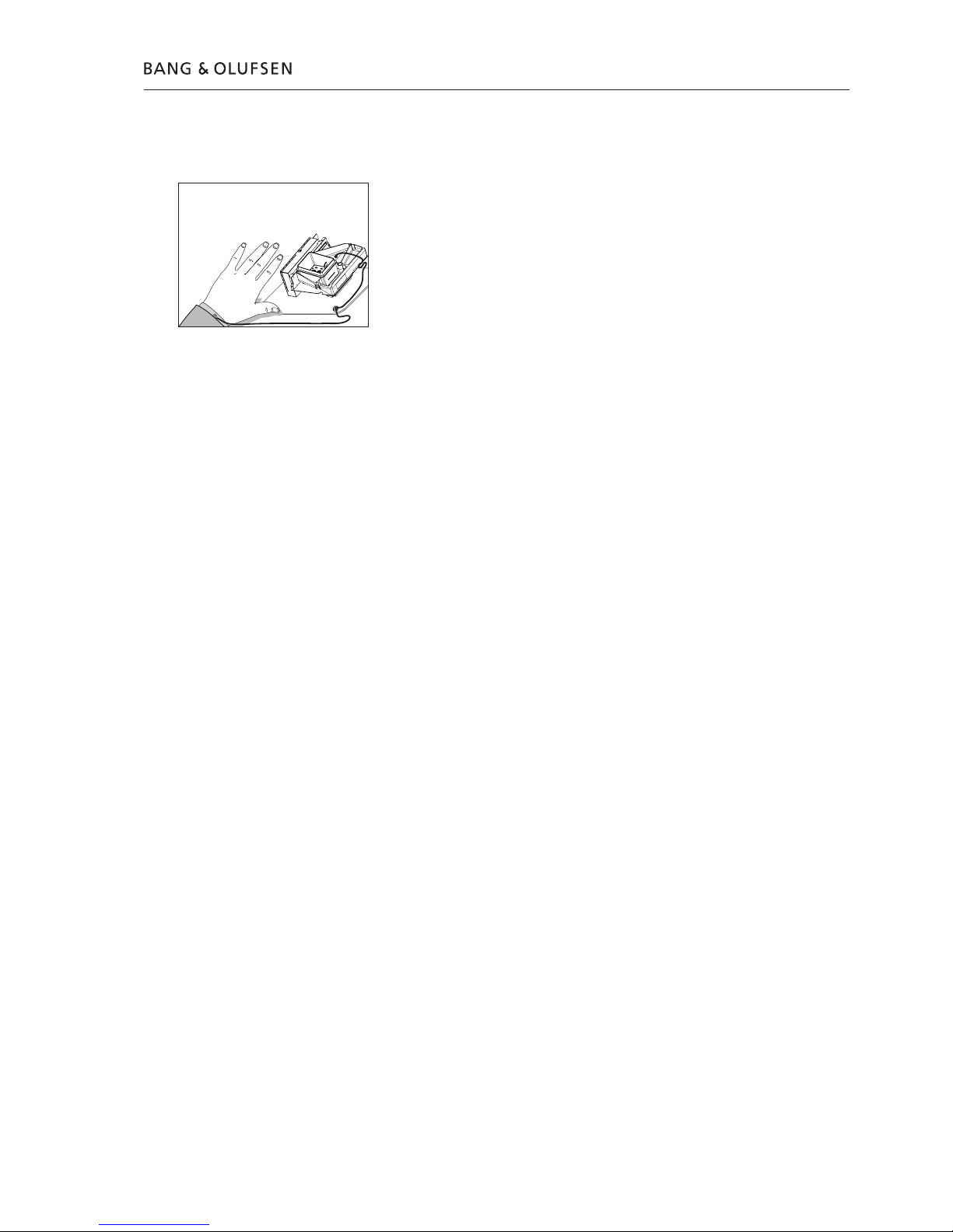
Handling
Wear cotton gloves to avoid any fingerprints on the product.
The surfaces on the product are very sensitive, so handling should be done with
great care to avoid damage.
Cleaning
Clean the surfaces of the BeoLab 4000 MKII using a soft, lintfree cloth which you
have wrung firmly in a solution of lukewarm water containing a few drops of mild
household cleaner, for example a dish washing detergent. The cooling fins on the
rear may be cleaned using a soft brush or a vacuum cleaner. The front cloth may
be cleaned with a vacuum cleaner set to the lowest level.
Note: Never use alcohol or other solvents to clean any part of the BeoLab 4000 MKII !
Insulation test
The product must be insulation tested after having been dismantled. Make the test
when the set has been reassembled and is ready to be returned to the customer.
Flashover must not occur during the test.
Make the insulation test as follows:
Short-circuit the two pins of the mains plug and connect them to one of the
terminals of the insulation tester.
Connect the other terminal to ground on the Power Link socket.
NOTE!
To avoid damaging the product it is essential that both terminals of the insulation
tester have good contact.
During the test the current must not exceed 10 mA.
Slowly increase the voltage on the insulation tester until a voltage of 2.5 kV (ac) is
obtained. Maintain the voltage level for one second, then slowly decrease the
voltage to 0 V (ac).
ESD
ESD-Mat
Warnings – Insulation test 2.1

Adjustments
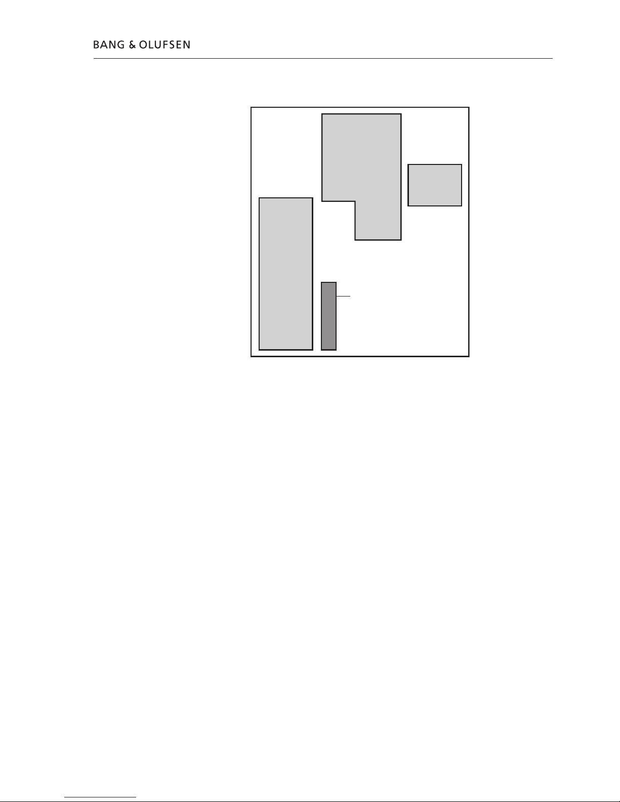
Adjustments after replacing PCB03, Main PCB
Read out the adjustment position of the old potentiometers, R301 & R312, and
set the new potentiometers to the same position.
Adjustments of bass/treble levels
Each loudspeaker is individually adjusted from production to ensure optimal stereo
perspective. When replacing a speaker unit or PCB03, Main PCB, bass/treble levels
have to be adjusted. On the back of the new speaker unit will be printed a rated
value for the sensitivity of the particular unit. The rated value is stated in dB and
have to be converted to a mechanical position of the two potentiometers by using
table 1 and fig.1.
After replacing a speaker unit
- Adjust treble level by means of (R301) and the bass level by means of (R312).
These two potentiometer are accessible via the two holes in the socket well, see
fig. 1.
- Adjusts according to the drawing and table 1. Only the potentiometer of the
replaced unit have to be adjusted.
WARNING: Do under no circumstances adjust the level of a unit that has not been
replaced!
Table 1
‘‘Clock position’’
(The new position
of the
potentiometer)
Bass deviation ±dB Treble deviation ±dB
0830 +3.1 +3.9
0900 +2.7 +3.3
1000 +1.8 +2.2
1100 +0.9 +1.1
1200 0.0 0.0
0100 -0.9 -1.1
0200 -1.8 -2.2
0300 -2.7 -3.3
0330 -3.1 -3.9
Fig.1
LI NE
L
R
1 2
POW ER
LIN K
W T
12
3
1
2
11
10
9
3.1 Adjustments
Repair tips
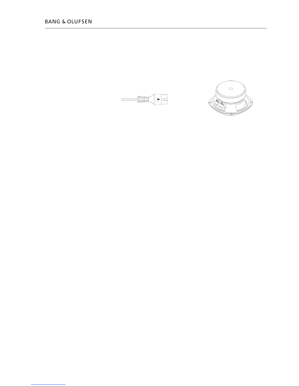
Hum in loudspeaker when no music is played
The Power Link cable must be of type MK III or higher.
The ground connection in Power Link cable lower than MK III may be insufficient
for optimum sound performance.
Power Link
MK III
Check loudspeaker units
The loudspeaker units can be checked by an ohm-meter.
OK values for tweeter and woofer are approx. 6 W.
How to check the Switch Mode Power Supply
- Take off the baffle.
- Connect an audio signal (set the input switch corresponding to the applied signal).
- Connect mains, 100 - 240V.
- Confirm 12V standby on PCB02, SMPS P2 pin 6, GND pin 3 (if not OK, replace
PCB02, SMPS).
- Confirm 12V HT_ON, on PCB02, SMPS P2 pin 8 (if not OK replace PCB03, Main
PCB).
- Confirm ±12V on PCB02, SMPS P2 +12V pin 1, 2 and -12V pin 4, 5 (GND pin 3).
If not OK replace PCB02, SMPS.
Repair tips 4.1

4.2
 Loading...