

Bang & Olufsen 4629 Service Manual

DVD 2
Type 4629
Service Manual
English
German, French, Italian, Spanish, Danish, Dutch and Simplified Chinese
versions are available in the Retail System
This Service Manual must be returned
with the defective parts/back-up suitcase !

CONTENTS
Survey of modules .................................................................. 1.1
How to service ........................................................................ 1.2
Service Mode .......................................................................... 2.1
Fault flow chart ...................................................................... 3.1
Adjustments ............................................................................ 4.2
Software update .................................................................... 4.9
Repair tips .............................................................................. 4.13
Final check after repair ........................................................ 4.14
Replacement of modules ....................................................... 5.1
Specification guidelines for service use ................................ 6.1
Wiring diagram ...................................................................... 7.1
Block diagrams ....................................................................... 7.2
Available parts ........................................................................ 8.1
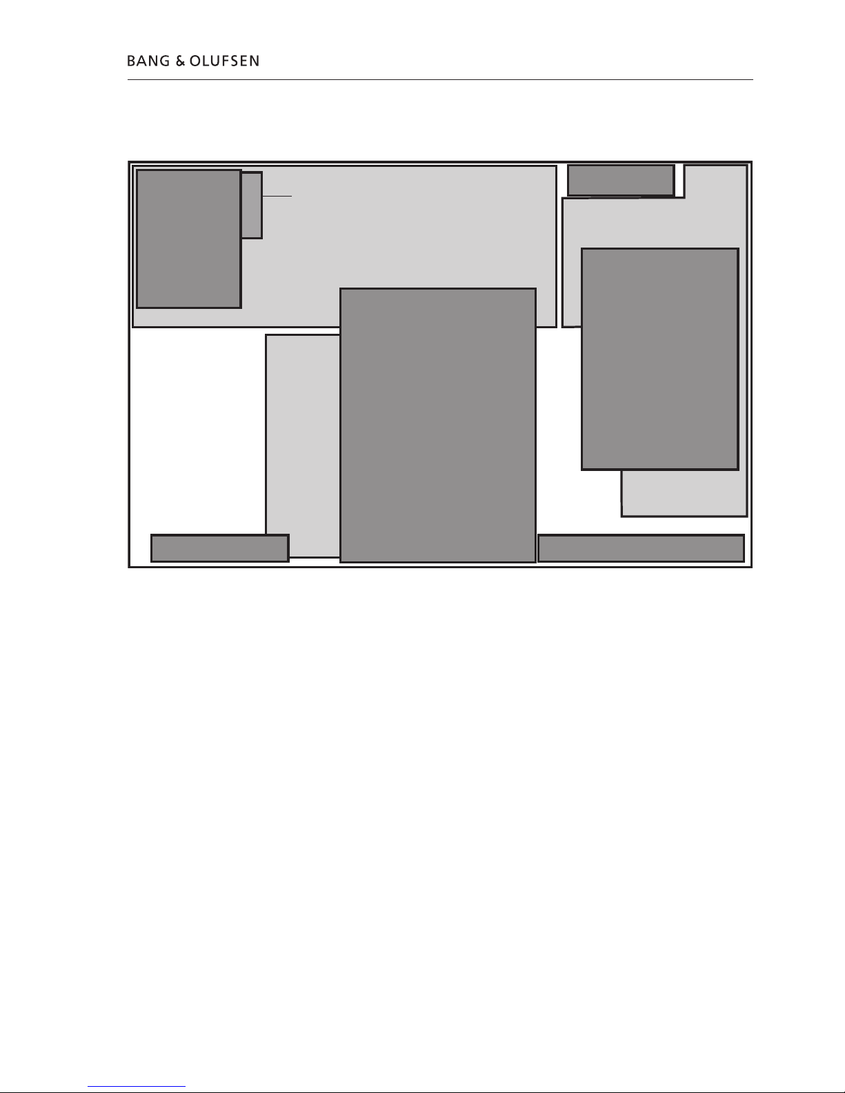
Survey of modules
Survey of modules 1.1
05
10
03
04
01
02
14
95
94
FAN
PCB01 Analog
PCB02 Digital
PCB03 Display
PCB04 Power Supply
PCB05 AV Input
PCB10 HDMI
PCB14 Keyboard (AVL)
94 Module Harddrive (HDD)
95 Module DVD Drive
Fan

How to service
Front line service
The static-protective field service kit must always be used when DVD 2 is
disassembled or modules are being handled.
It is not allowed to solder in the customer’s home. Therefore, accessible modules
are mounted with plugs and connectors, and can be exchanged without the use
of a solder iron.
DVD 2 has been developed for simple module exchange to comply with the on-site
service strategy. Module exchange is possible on-site, at the dealershop or in the
service workshop, whatever is most convenient in each case. For on-site service a
Back-up suitcase must be used.
Module exchange is the recommended way to perform service, due to the fact
that most of the modules are multi-layer based, and most of the circuits are on a
single main PCB.
An electrical fault symptom can be removed during one visit to the customers
home, if you bring a DVD 2 Back-up suitcase with you.
Is it a mechanical symptom, the specific part must be brought with you separately.
Service documentation
Service documentation for DVD2 will be a Service Manual with part nos. for the
Back-up suitcase, electrical and mechanical parts, User’s guides, etc.
In the Back-up suitcase, an enclosed appendix with detailed description of
available nuclei will be located. This could be helpful when operating in
service mode.
Preparations before service
Fault description and error codes must be returned with the replaced parts.
Use the Module Repair form or the form in the Retail Order System, Exchange
Module. To help the Bang & Olufsen Module Repair department it is very
important that you answer the following questions:
1 Which products are in the setup?
2 Which software versions are used in these products?
3 How are the products linked together?
4 What happens in the actual situation?
Note: In this case, the error code is generated by the Diagnostic Software and
contains 6 decimal numbers, it is not possible to clear the error code.
Recommended tools for service
Service cable
Software disc
DVD/CD Player Test Pack
White cotton gloves
Soft lint-free cloth
1.2 How to service
How to service 1.3
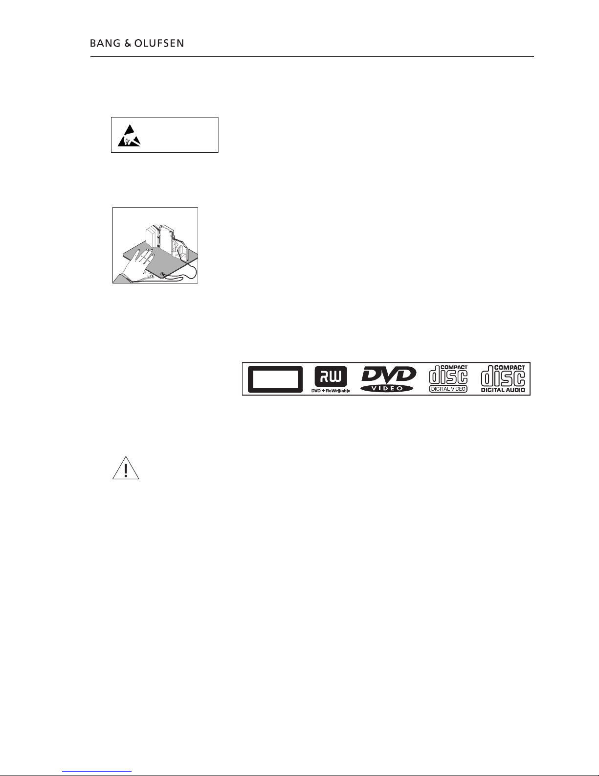
Warnings
ESD
The internal electronics are very sensitive to static electricity, which may damage
the product.
When electrical replacement or disassembly is necessary, use ESD-mat and tools.
Static-protective field service kit
A static-protective field service kit must always be used when the product is
disassembled or modules are being handled.
Follow the instructions in the guide and use the ESD-mat for both old and new
modules.
Please note:
When mains voltage on the product is required, remove the connection between
the product and the ESD-mat.
The chassis or modules must always be connected to the static-protective field
service kit or placed in an ESD-proof bag.
Laser exposure
The DVD 2 contains a laser system and is classified as a class 1 laser product.
The DVD 2 must be opened by qualified personal only.
Symbol of safety components
When replacing components with this symbol, the same type has to be used, also
the same values for ohm and watt.
The new component is to be mounted in the same way as the replaced one.
General Warnings
Wear cotton gloves to avoid fingerprints on the product.
The aluminium and display surface on the product is very sensitive, so handling
should be done with great care to avoid damage.
When transporting the DVD 2, it is recommended to use the product cover.
Do not move the product or the HDD when it is operating. The HDD is very
sensitive to bumps which can cause great damage.
Cleaning
Clean the DVD 2 surfaces using a lint-free cloth which you have wrung firmly in
lukewarm water.
Never use alcohol or other solvents to clean any parts of the DVD 2.
STATIC ELECTRICITY
MAY DESTROY THE
PRODUCT
ESD
CLASS 1
LASER PRODUCT

1.4
Service Mode
Diagnostic Software(DS)
Service Mode in DVD 2 is a new software implemented in the PCB02, Digital and
is called ‘Diagnostic Software’. The Diagnostic Software consists of independent
‘atomic’ tests, called nuclei. Each nucleus forms a test to indicate possible
hardware failure.
Execution of each test is done by typing individual nucleus numbers in the
command promt line (a promt in the ‘Diagnostic Software’), which look like this:
DS:>
In this case use ‘HyperTerminal’ as user interface. HyperTerminal is a ‘Windows’
component, please see next page for setup.
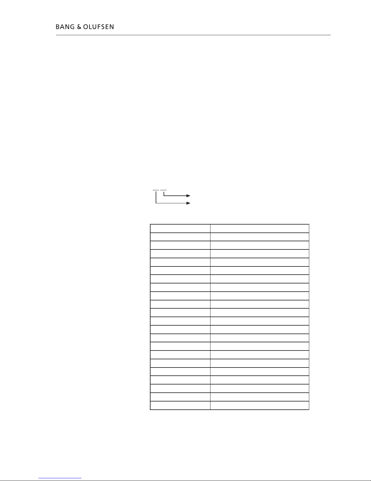
Each nucleus has a unique number of four digits. This number is the input of the
command line interface.
[ XX YY _ _ ]
Nucleus number
Nucleus group number
The Nucleus groups are defined as follows:
Service Mode 2.1
Nucleus Group Number Nucleus Group Name
0 Scripts
1 Codec (e.g. Chrysalis, Leco)
2 Boot EEPROM
3 NVRAM
4 SDRAM
5 FLASH
6 Video Input Processor
7 DVIO
8 Progressive Scan
9 Basic Engine
10 Display and Control Board
11 Analogue Board
12 System
13 Electronic Program Guide Board
15 HDMI
16 Analogue Slave Processor
17 Analogue Board EEPROM
18 Video Matrix
19 Audio Matrix
20 Front End
21 Hard Disk

2.2 Service Mode
The Nucleus numbers are individual 2 digit numbers according to specific tests, and
are listed in a ‘detailed description of available nuclei’ which is an appendix to
the service manual.
In this description, there will be technical expressions like e.g. CHR and DVIO, which
are abbreviations for ‘Codec Host Repository’ and ‘Digital Video Input Output’ .
For an easy overview these are listed in the glossary below:
Glossary
AC3 : Audio Compression format 3
ACK : Acknowledge
ADC : Analogue to Digital Conversion
AMIX : Audio Matrix (Audio switching)
ANAB : Analogue Board
AROM : Analogue Board EEPROM
ASP : Analogue Slave Processor
ATA : AT Attachment
ATAPI : AT Attachment Packet Interface
BE : Basic Engine
BROM : BOOT EEPROM
CHR : Codec Host Repository
CRC : Cyclic Redundancy Check
DAC : Digital to Analogue Conversion
DB : Digital Board
DCB : Display and Control Board
DENC : Digital (video) ENCoder
DMA : Direct Memory Access
DS : Diagnostic and Service Software
DSP : Digital Signal Processor
DTTM : Digital Terrestrial Tuner Module
DV : Digital Video
DVIO : Digital Video Input Output
EPGB : Electronic Program Guide Board
FRE : Front End (Tuner)
HDD : Hard Disk Drive
HDMI : High Definition Multimedia Interface
IC : Integrated Circuit
IDE : Integrated Drive Electronics
IH : Interface Handler
IIC : Inter IC Communication
INT : Interrupt
LED : Light Emitting Diode
NVRAM : Non Volatile Random Access Memory
OPC : Optimal Power Control
PIO : Peripheral IO pin
PSCAN : Progressive Scan
RC : Remote Control
S2B : Serial to Basic Engine
SYS : System
TOC : Table Of Contents
UART : Universal Asynchronous Receiver Transmitter
UDF : Universal Disc Format
VIP : Video Input Processor
VMIX : Video Matrix (Video switching)
Service Mode 2.3
Setup & Connection
Tools required
To enter Service Mode it is necessary to connect DVD 2 to a PC with a service
cable. The required tools are:
- PC with com port (if no com port is available, use USB/COM converter part. no.
3375151)
- Service Cable ( part.no. 6278222 )
- HyperTerminal ( Windows Component)
Setup
The first-time setup is described below. This is a one time only procedure.
1. Open PC or laptop (if no COM port is available, connect USB/COM Converter)
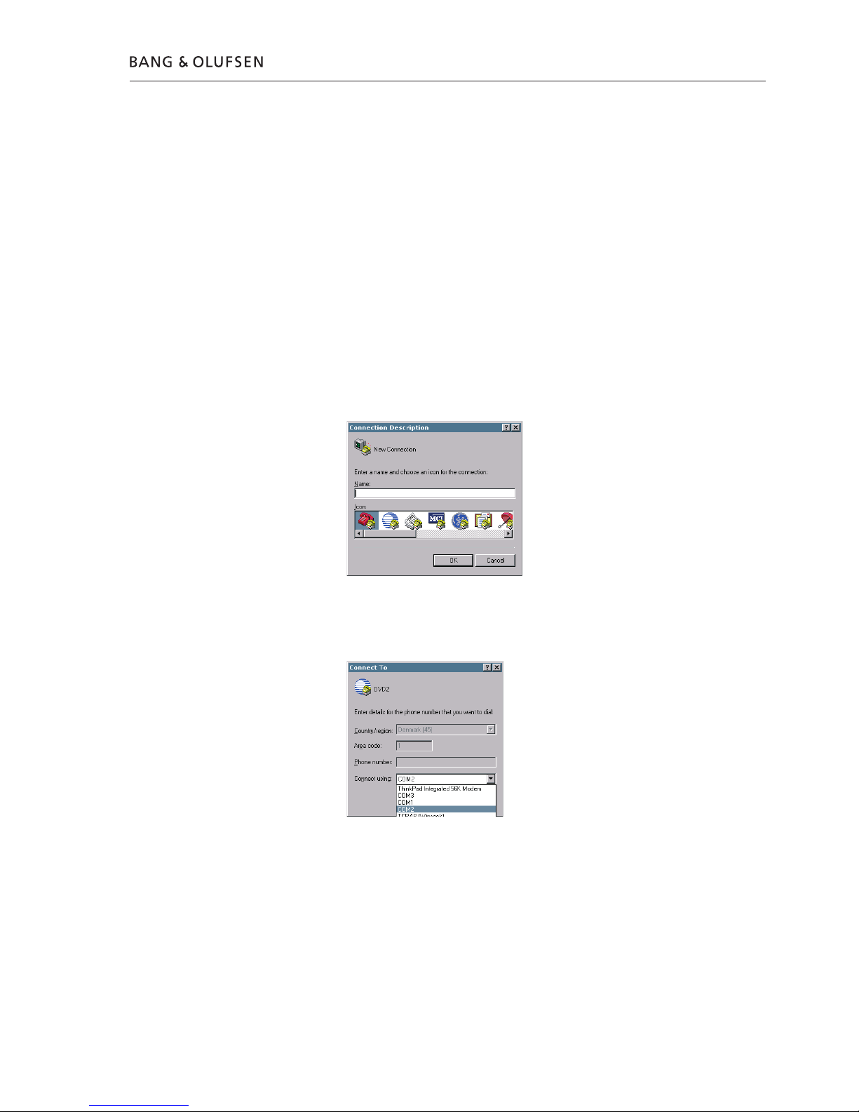
2. Run HyperTerminal (usually placed: Start/Programs/Accessories/Communications)
3. The ‘Connection description’ box appears on the screen
In the line ‘Name’ type ‘DVD2’ and choose an icon for the connection. Click OK.
The following appears on the screen:
In the line ‘Connect using’ choose the COM port (if USB/COM converter is used,
choose the ‘virtual COM port’ that represent the USB-converter) to be used.
Click OK.
2.4 Service Mode
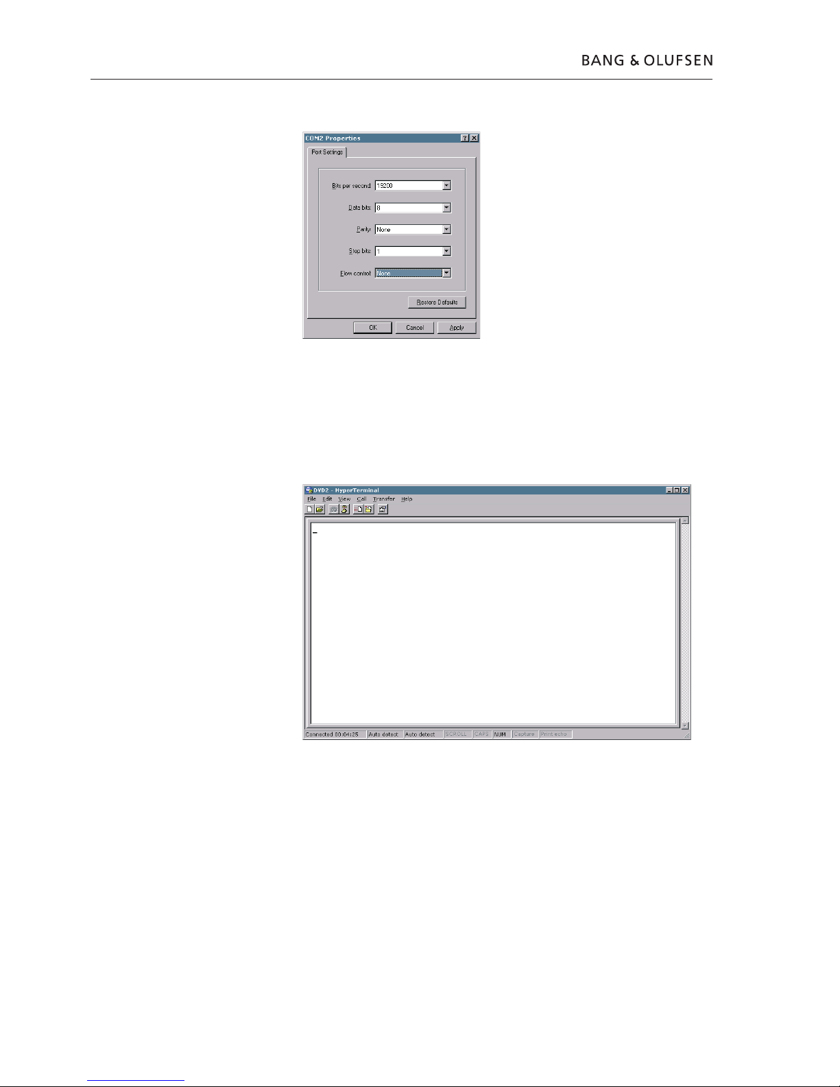
The following appears on the screen.
Use the following Port Settings:
Bits per second 19200
Data bits 8
Parity None
Stop bits 1
Flow control None
Click OK to continue. The following window should appear on the screen.
Now the HyperTerminal is ready to use, but before going any further it would be
wise to save the connection setup, in this way it will be easy to connect next time.
This can be done in following way: Click ‘File’, Click ‘Save As.’
The ‘File Name’ is already suggested as ‘DVD2’, but the location in the line
‘Save in’ should be changed to a known location e.g. ‘Desktop’, for easy access.

Service Mode 2.5
Activation
1. Disconnect DVD 2 from the mains
2. Connect Service Cable from P1103 on PCB02 to COM port
3. Open HyperTerminal
4. Power on DVD 2 and confirm the following ‘read out’ in the HyperTerminal window:
Factory Diagnostics and Service Software
DVD Video Recorder (Sep 28 2006, 18:29:46)
Version :1388 Build :20060928_1821
Release :SG1_1 Buildtype :dev
Baseline :SGP29atl#SG1_1_20050609_base Variant :sxc
DS:>
Usage
The commands that can be given are the numbers of the nuclei. A command must
be terminated with an <ENTER> character from the control PC. When typing
commands, the backspace key can be used to make corrections. Apart from this,
the Up and Down arrows can be used to browse through previous commands.
When non-supported commands are entered, the interface returns to the
command prompt line DS:>
E.g.
DS:> 1888
DS:>
If the command (the nucleus number) is recognised, the nucleus is executed.
Result and output of an activated (and terminated) nucleus will be sent back to
the control service PC.
Example in case the command is correct:
DS:> 1200
120000: Hardware ID = 0x27
Test OK @
DS:>
Example in case there is an error in the communication:
DS:> 1100
110002: Communication with PCB01, Analog fails
Error @
DS:>

2.6 Service Mode
ERROR handling
When a command is terminated by the user, and an error occurs in the communication,
the results are returned from a diagnostic nucleus to the control/service PC.
The result looks as follows
<number> : <string> [ Error] @
<number> is a 6-digit decimal number padded with leading zeros if its value is less
than 6 digits. The first four digits identify the generating nucleus (group and nucleus);
the last two digits indicate the error number.
[ XX YY ZZ ]
Error Code
Nucleus Number
Nucleus Group Number
For further specifications please refer to the enclosed appendix.
Cancelling Service Mode
To cancel Service Mode, disconnect DVD 2 from mains and wait 10 sec. before
rebooting the system.
End User/Dealer script
The ‘End User/Dealer script interface’ gives a diagnosis on the DVD 2.
During this mode, a number of hardware tests (nuclei) are automatically executed
to check if the recorder is faulty. The diagnosis is simply a “FAIL” or “PASS”
message. If the message “FAIL” appears on the display, there is apparently a
failure in the recorder. If the message “PASS” appears, the nuclei in this mode
have been executed successfully. There can be still a failure in the recorder because
the nuclei in this mode do not cover the complete functionality of the recorder.
Before the product is returned to the customer this ‘End User/Dealer script’ test
must be executed to ensure correct functionality of the recorder. If the test fails,
continue to the fault flow chart to locate the error.
This test can be executed by:
1. Typing ‘script’ in the command promt line (see section fault flow chart for further
information)
or by
2. Pressing button ‘S6’ on back panel when connecting to the mains. The DVD
Recorder is tested stand-alone: no other equipment than the DVD Recorder is
needed.
Cancelling ‘End User/Dealer script’
To cancel ‘End User/Dealer’ script, disconnect DVD 2 from mains and wait 10 sec.
before rebooting the system.

Fault flow chart 3.1
Dealer test
Perform built-in dealer test:
- Unplug power cord
- Press and hold ‘play’ buton (S6)
- Connect to mains and release button after 2 sec.
PASS in display = No errors found
FAIL xxxxxx = Error found in DVD 2
If the Dealer test fails in the test sequence, it will display an error code.
Locate the error code and refer to the error list in enclosed appendix.
If it is not possible to locate the error code, and the DVD 2 is still faulty, continue
with the fault flow chart.
Fault flow chart
No start up .......................................................................... 3.2
DVD 2 does not complete startup sequence ......................... 3.6
DVD 2 starts up but goes to standby .................................... 3.8
Fan error .............................................................................. 3.9
HDD playback check .......................................................... 3.10
DVD playback check .......................................................... 3.10
Manual recording with TSB (Time Shift Buffer) ................... 3.11
Manual HDD recording ...................................................... 3.12
No audio ........................................................................... 3.13
No picture ......................................................................... 3.15
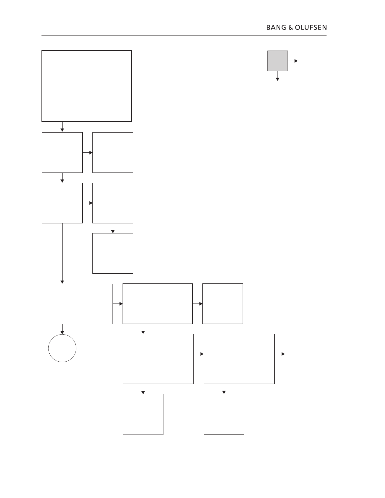
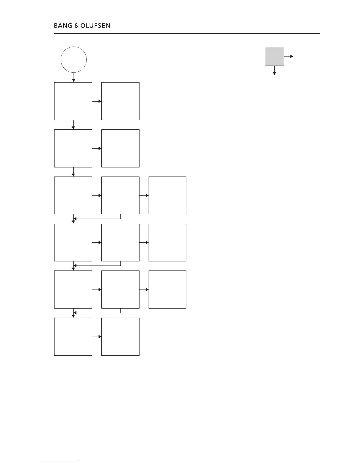
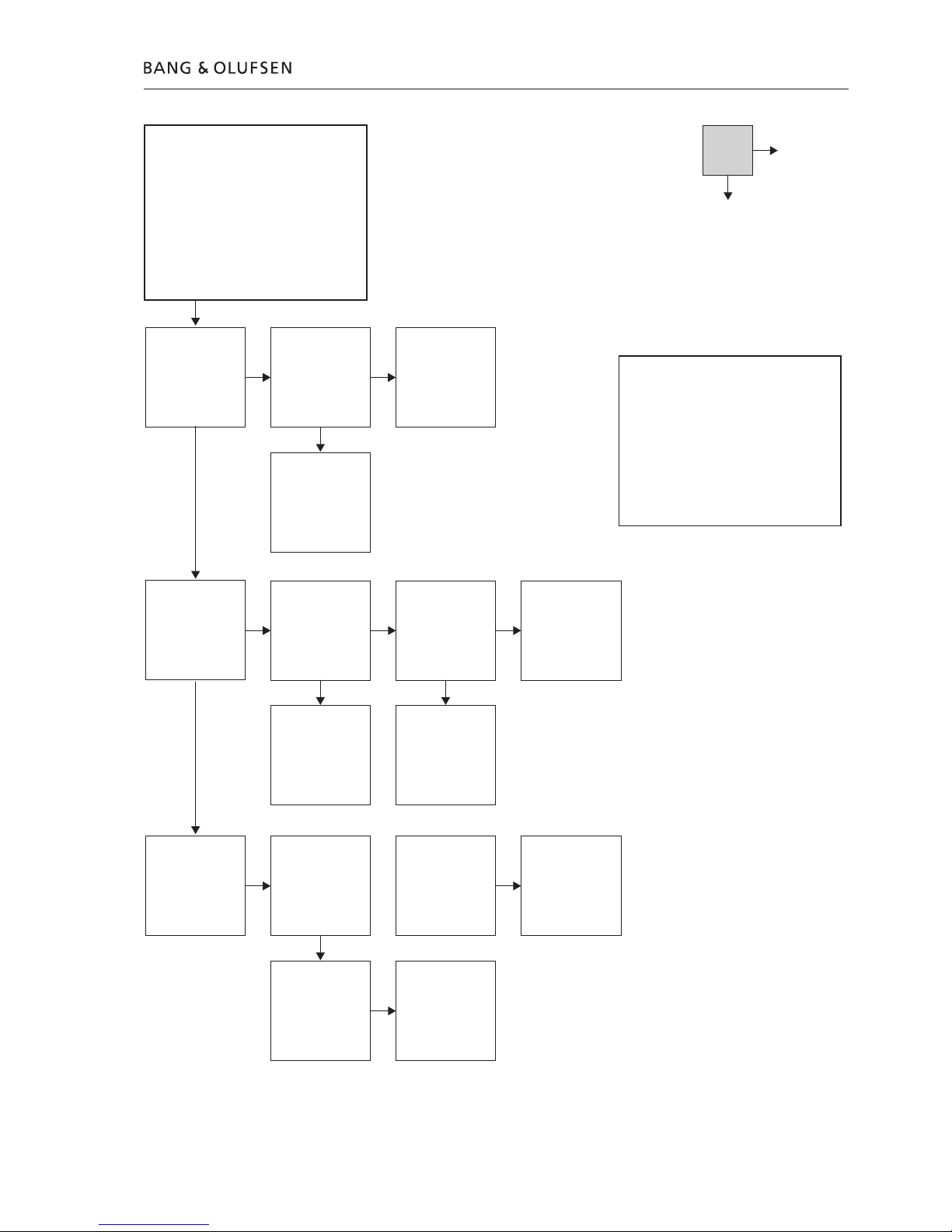
3.2 Fault flow chart
Confirm the mains
supply is connected
and applied
OK?
Fault symptom:
No start up
No STBY. LED (normally red)
No Display
Possible causes:
Mains not supplied
Blown fuse F1 on PCB04, Power Supply
Missing voltages
Defective PCBs
Defective cables
Reconnect J2 on PCB04, Power Supply
Disconnect cable P1101 on PCB14,
Keyboard
Confirm:
+3.3V Stby. on PCB04, J2 pin 5
+5V Stby. on PCB04, J2 pin 3
+12V Stby. on PCB04, J2 pin 1
OK?
Replace PCB04,
Power Supply
Disconnect J2 on PCB04, Power Supply
Confirm:
+3.3V Stby. on PCB04, J2 pin 5
+5V Stby. on PCB04, J2 pin 3
+12V Stby. on PCB04, J2 pin 1
OK?
Confirm:
+3.3V Stby. on PCB04, J2 pin 5
+5V Stby. on PCB04, J2 pin 3
+12V Stby. on PCB04, J2 pin 1
OK?
Replace fuse F1 on
PCB04 and connect
to mains
Does fuse F1 on
PCB04, Power Supply
blow again?
Fuse F1 on PCB04,
Power Supply
OK?
Replace/reconnect
mains cable
Replace PCB14,
Keyboard
Replace PCB03,
Display
Replace PCB01,
Analog
Reconnect P1101 on PCB14
Disconnect P1100 on PCB14, Keyboard
Confirm:
+3.3V Stby. on PCB04, J2 pin 5
+5V Stby. on PCB04, J2 pin 3
+12V Stby. on PCB04, J2 pin 1
OK?
Replace PCB04,
Power Supply
Go to next
page
No
Yes
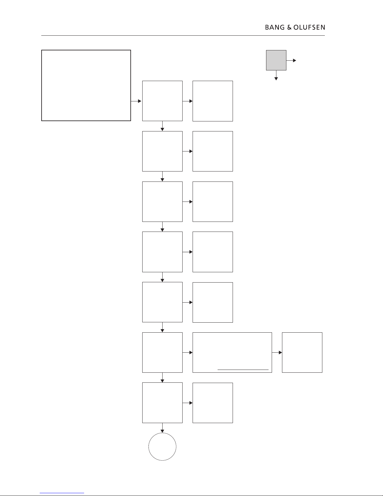
Fault flow chart 3.3
From previous
page
Confirm:
3.3V on PCB04, J1 pin 1, 2, 3, 4
5V on PCB04, J2 pin 9
-5V on PCB04, J1 pin 12
OK?
Replace PCB02,
Digital
Refer to ‘Adjustments’
when replacing
Replace PCB04,
Power Supply
Replace PCB10,
HDMI
Go to next
page
No
Yes
Disconnect J1 on PCB04, Power Supply
Confirm:
3.3V on PCB04, J1 pin 1, 2, 3, 4
5V on PCB04, J2 pin 9
-5V on PCB04, J1 pin 12
OK?
Reconnect J1 on PCB04, Power Supply
Disconnect P1004 on PCB02, Digital
Confirm:
3.3V on PCB04, J1 pin 1, 2, 3, 4
5V on PCB04, J2 pin 9
-5V on PCB04, J1 pin 12
OK?
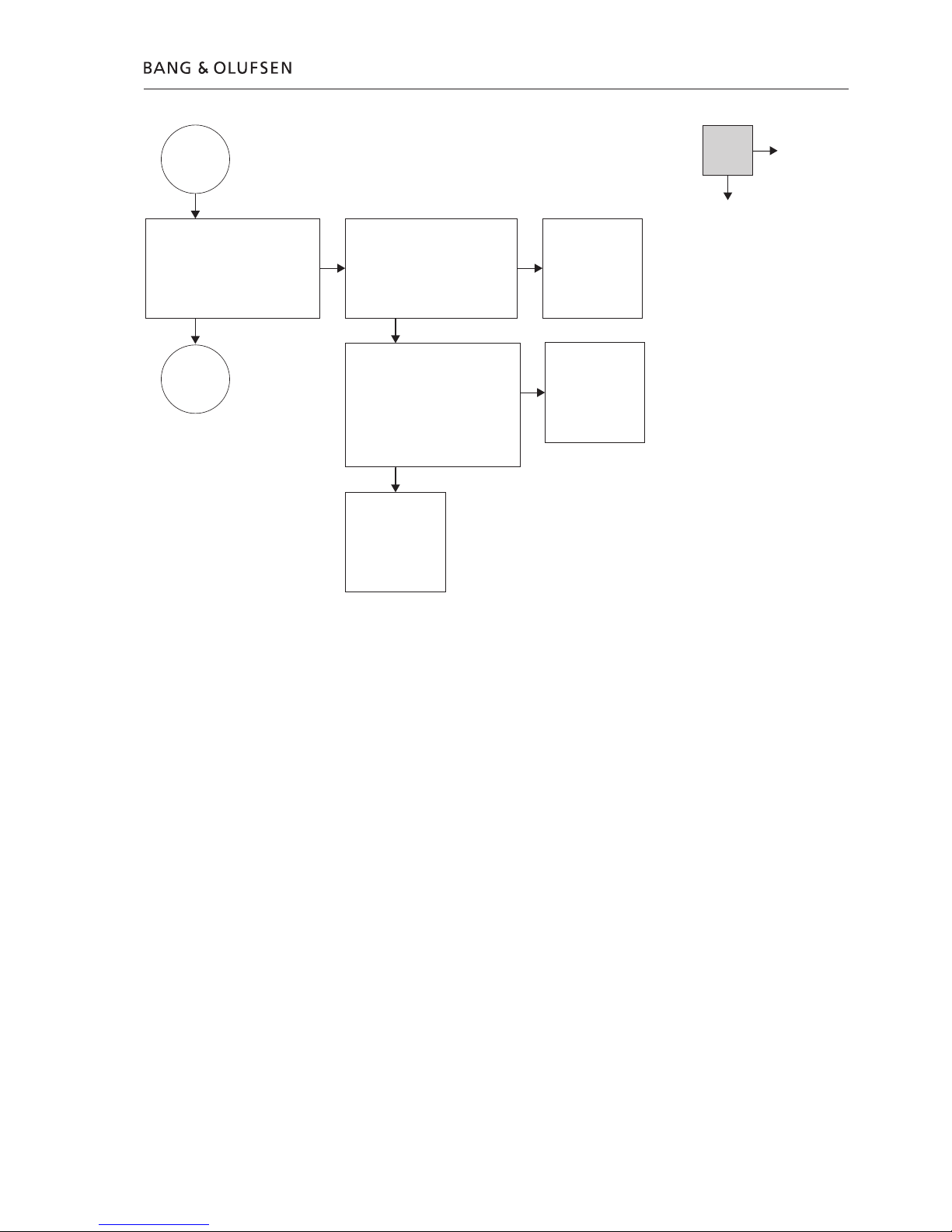
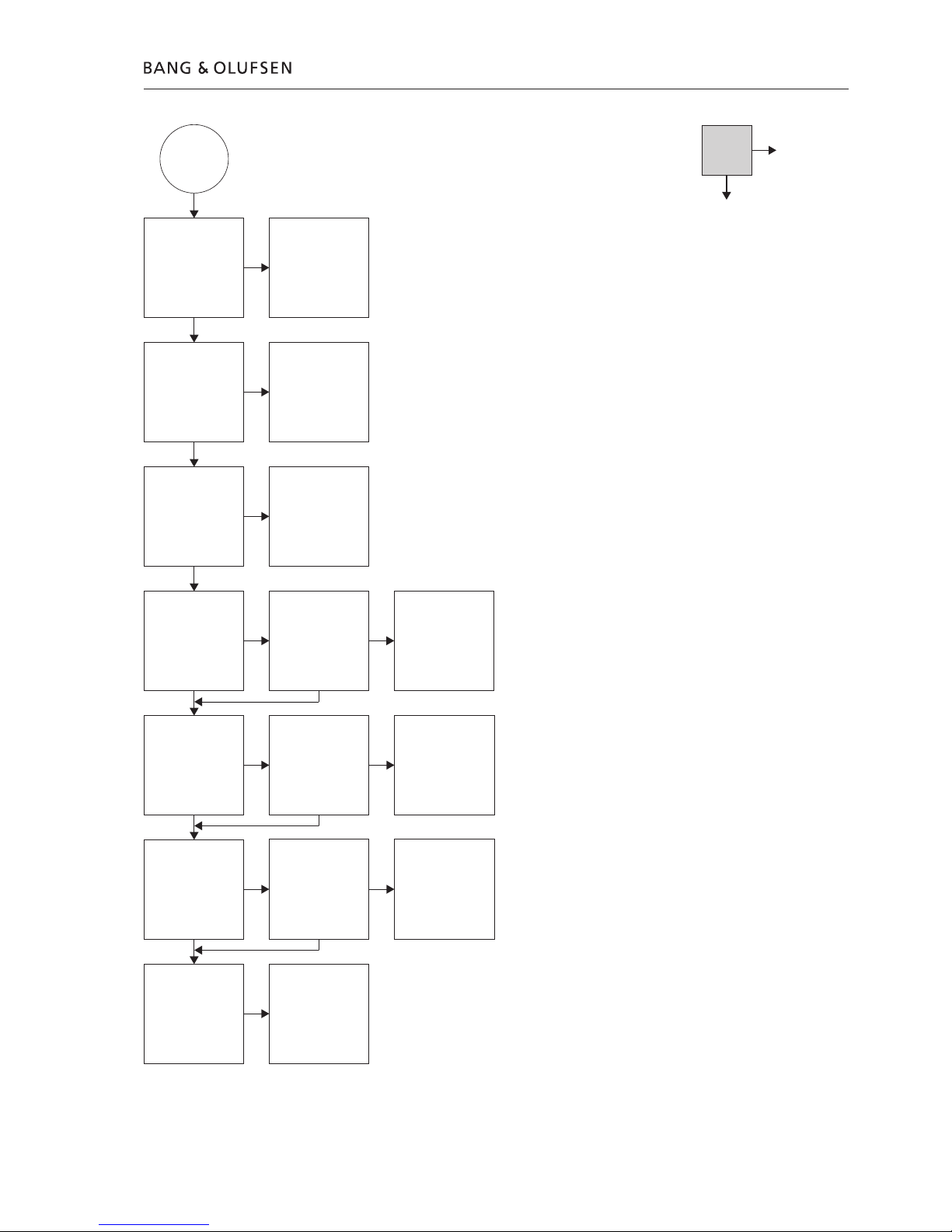
3.4 Fault flow chart
From previous
page
Start HyperTerminal
(Refer to Service Mode for use)
Is HyperTerm promt OK?
Replace PCB01,
Analog
HyperTerm OK?
Reconnect/Replace
cable W16
Replace PCB02,
Digital
HyperTerm OK?
Go to next
page
No
Yes
Confirm:
3.3V Stby. on PCB01, P1932 pin 5
5V Stby. on PCB01, P1932 pin 3
12V Stby. on PCB01, P1932 pin 1
OK?
Confirm:
3.3V on PCB03, P1500 pin 1, 2, 3, 4
5V on PCB02, P1500 pin 9
-5V on PCB02, P1500 pin 12
OK?
Replace PCB14,
Keyboard
HyperTerm OK?
Disconnect PCB10,
HDMI
HyperTerm OK?
Replace PCB10,
HDMI
Is DVD 2 OK?
Otherwise start at the
beginning with the
new PCB
Is DVD 2 OK?
Otherwise start at the
beginning with the
new PCB
Is DVD 2 OK?
Otherwise start at the
beginning with the
new PCB
Is DVD 2 OK?
Otherwise start at the
beginning with the
new PCB
Reconnect/Replace
cable W10
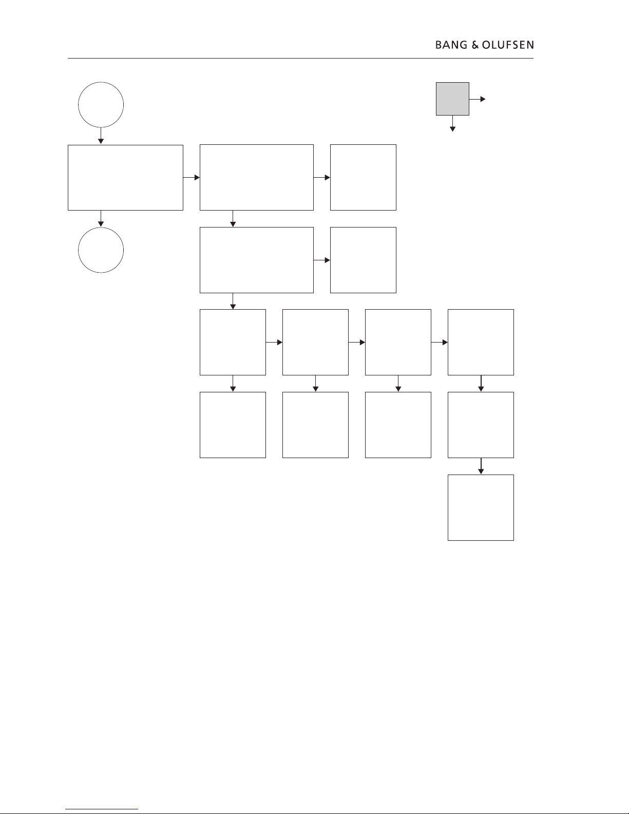
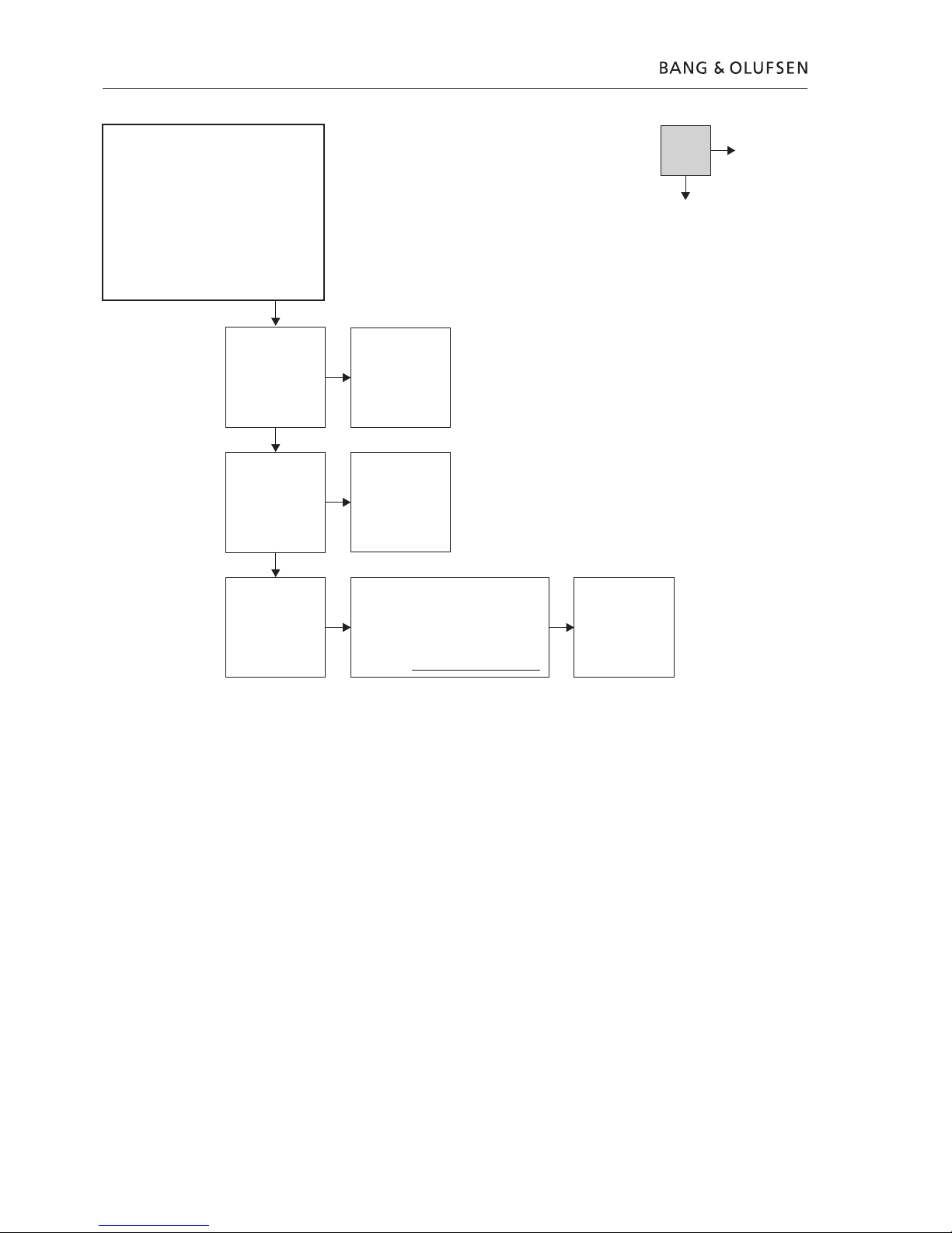
Fault flow chart 3.5
From previous
page
Confirm
communication with
PCB02, Digital by
typing:
DS:>1228 at prompt
OK?
Replace PCB02,
Digital
Refer to ‘Adjustments’
when replacing
Confirm
communication with
ASP on PCB01,
Analog by typing:
DS:>1600 at prompt
OK?
Set slash by typing
‘DS:1217 11221’ at
prompt
Confirm result by
typing DS:>1218
OK?
No
Yes
Replace PCB02,
Digital
Refer to ‘Adjustments’
when replacing
Replace PCB01,
Analog
Confirm ‘diversity
string’ by typing:
DS:>1229 at prompt.
Result must be a ‘128-
digit-decimal-number’
OK?
To set ‘diversity string’
please refer to
‘Adjustments’
Confirm result by
typing DS:>1208
OK?
Confirm
‘SettingsDisplay’ by
typing:
DS:>1228 at prompt
OK?
Replace PCB02,
Digital
Refter to
‘Adjustments’ when
replacing
Replace PCB02,
Digital
Refer to ‘Adjustments’
when replacing
Confirm IEEE unique
number by typing:
DS:>1208 at prompt
Result must be a ‘10-
digit-hexadecimal-
number’
OK?
Set IEEE unique
number by typing
DS:>1207 xxxxxxxxxx
at prompt. Confirm
result by typing
DS:>1208
OK?
Confirm ‘slash
version’ by typing:
DS:>1218 at prompt.
Slash version must be
‘11221’
OK?
Replace PCB02,
Digital
Refer to ‘Adjustments’
when replacing
3.6 Fault flow chart
Confirm:
+5V on
PCB04 J5 pin 4
+12V on PCB04 J5
pin 1
OK?
Fault symptom:
DVD 2 does not complete startup sequence
STBY. LED (red -> green)
Display shows ➀ or ➁
➀ ‘BUSY’ for about 45 sec., then ‘STARTING’
for about 15 sec., then ‘CLOCK’
➁ ‘STARTING’ and HDD reboots for every 45 sec.
Possible causes:
Defective DVD ‘DVD Drive’
Defective HDD
Defective PCB
Replace DVD Drive
Start HyperTerminal
(Refer to
Service Mode for use)
Confirm
communication with
DVD Drive by typing:
DS:>900 at prompt
Test OK?
Replace PCB04,
Power Supply
Replace DVD Drive
No
Yes
Confirm ‘open/close’
function by typing:
DS:>904 at prompt
(open)
DS:>905 at prompt
(close)
Test OK?
Replace HDD
(Check cables W11 &
W13 before replacing)
Refer to ‘Adjustments’
when replacing
Replace PCB10, HDMI
Confirm
communication with
PCB10, by typing:
DS:>1501 at prompt
Test OK?
Confirm HDD
diagnostic test by
typing:
DS:>2105 at prompt
Test OK?
Perform an ‘image download’ from DVD
format disc, by typing:
DS:>2107 at prompt
Refer to ‘Adjustments’ for further
information
(Formatting a new HDD)
WARNING!: All recording data will be lost
Replace HDD
(Check cables W11 &
W13 before replacing)
Refer to ‘Adjustments’
when replacing
Confirm
communication with
HDD by typing:
DS:>2100 at prompt
Test OK?
Replace PCB04,
Power Supply
Check HDD
Confirm:
+5V on PCB04 J4
pin 4
+12V on PCB04 J4
pin 1
OK?
See next page
Fault flow chart 3.7
Confirm
communication with
FrontEnd (Tuner) on
PCB01, by typing:
DS:>2000 at prompt
Test OK?
Confirm
communication with
ASP on PCB01 by
typing:
DS:>1600 at prompt
Test OK?
Confirm
communication with
PCB02 by typing:
DS:>100 at prompt
Test OK?
Confirm ‘slash version’
by typing:
DS:>1218 at prompt
Slash version must be
‘11221’
Test OK?
Confirm IEEE unique
number by typing:
DS:>1208 at prompt
Result must be a ‘10-
digit-hexadecimal-
number’
Test OK?
Confirm ‘diversity
string’ by typing:
DS:>1229 at prompt
Result must be a ‘128-
digit-decimal-number’
Test OK?
Confirm
‘SettingsDisplay’ by
typing:
DS:>1228 at prompt
Test OK?
Replace PCB01,
Analog
Replace PCB01,
Analog
Replace PCB02,
Digital
Refer to
‘Adjustments’ when
replacing
Set slash by typing:
DS:>1217 11221 at
prompt
Confirm result by
typing:
DS:>1218
Test OK?
Set IEEE unique
number by typing:
DS:>1207 xxxxxxxxxx
at prompt. Confirm
result by typing:
DS:>1208
OK?
To set ‘diversity string’,
please refer to
‘Adjustments’
Confirm result by
typing:
DS:>1208
Test OK?
Replace PCB02,
Digital
Refer to
‘Adjustments’ when
replacing
Replace PCB02,
Digital
Refer to ‘Adjustments’
when replacing
Replace PCB02,
Digital
Refer to ‘Adjustments’
when replacing
Replace PCB02,
Digital
Refer to ‘Adjustments’
when replacing
From previous
page
No
Yes
3.8 Fault flow chart
Confirm on PCB04,
Power Supply:
+5V on J4 pin 4
+12V on J4 pin 1
Fault symptom:
DVD 2 starts up but goes to standby
Stby. LED = Red
Display shows ‘STARTING’ and the DVD 2 is
locked!
After a few minutes DVD 2 reboots and the
sequence is repeated
Possible causes:
Defective HDD
Defective Power Supply
Replace HDD
(Check cables W11 &
W13 before replacing)
Refer to ‘Adjustments’
when replacing
Start HyperTerminal
(Refer to Service Mode
for use)
Confirm
communication with
HDD by typing:
DS:>2100 at prompt
Replace PCB04,
Power Supply
Confirm HDD
diagnostic test by
typing:
DS:>2105 at prompt
OK?
No
Yes
Perform an ‘image download’ from DVD
format disc, by typing:
DS:>2107 at prompt
Refer to ‘Adjustments’ for further
information
(Formatting a new HDD)
WARNING!: All recording Data will be lost
Replace HDD
(Check cables W11 &
W13 before replacing)
Refer to ‘Adjustments’
when replacing
Fault flow chart 3.9
Is the Fan running
when DVD 2 is on?
Fault symptom:
Fan error
Fan continues running in standby
Fan not running
Fan always runs at high speed
Possible causes:
Defective Fan
Defective NTC on PCB03, Display
Defective software
Is the Fan speed
normal?*
Replace Fan
Confirm 5~12V on
PCB01 P1913
between pin 1 and
pin 2
OK?
Is DC level lower than
1.6V at PCB03 P1910
pin 8?
No
Yes
Verify that the
software version is the
latest available.
Refer to ‘Adjustments’
for readout
OK?
Update to latest
version. Software can
be downloaded at
Bang & Olufsen Retail
system under the
BeoWise section
Replace PCB01,
Analog
* Measuring made at 22 deg. celsius
Fan speed low (normal/switched on):
-5V PCB01 P1913 between pin 1 and pin 2
-1.6V or higher at PCB03 P1910 pin 8
Fan speed high (switched on):
-10~12V PCB01 P1913 between pin 1 and pin 2
- 1.6V or lower at PCB03 P1910 pin 8
Fan off (stby. only):
-1.9V or higher at PCB03 P1910 pin 8
Replace PCB03,
Display
Replace PCB01,
Analog
Confirm that Fan stops
running approx. 15
sec. after DVD 2 is
switched off
Is DC level higher than
1.9V at PCB03 P1910
pin 8?
Wait 1-2 minutes and
measure again
(DC level should
increase)
Replace PCB03,
Display
Verify that the
software version is the
latest available.
Refer to ‘Adjustments’
for readout
OK?
Update to latest
version. Software can
be downloaded at
Bang & Olufsen Retail
system under the
BeoWise section
 Loading...