

Bang & Olufsen 2651, 2652, 2653, 2654 Service Manual

rt.
Bang&Olufsen
BeoSound
Century
Typ€ 2651, 2652, 2654, 265/l
SERVICE MANUAL
Circuit Description
3540178 Danish
3540179
English
3540180 German
3540181 Fi€nch
2
2-1
2-2
Adjusffnents
..................
Tuner..........
Tape............
cD
...............
Loudspeaker
Replacement
of PCB 2 Amplifier
Replacement
of
PCB
3 or 31C4
Replacement
of a
speaker unit..............
Repair
tips
.............
Lubrication
Replacement
of CD drive mechanism
Tape Wow frequencies
Test
functions ...................
Test mode...
Display of tuner variant
Gearbox
test ...........,..
Keyboard test ..............
LED test
Display
of software version
Presetting
of EEPROM
Continuous operation
of tape recorder
Speaker
sound
level
adjustment
[ffi;;;; ;;;;;il;il::::::::
::::::: ::::::::::::::::::::::: :::::r ::::::::::::::::
GB
5-1
5-1
5-1
5-3
5-4
5-4
5-5
5-5
DF
5-10
5-22
5-10
5-22
5-10
5-22
5-13 5-25
5-14 5-25
5-14 5-25
5-15 5-27
5-15 5-27
5-17 5-29
5-17 5-29
5-17 5-29
5-17 5-29
5-17 5-29
5-18 5-30
5-18 5-30
5-18 5-30
s-18
5-30
5-18
5-30
5-18 5-30
5-19 5-31
5-19
s-31
5-19 5-31
5-19 5-31
5-20
5-32
5-6
5-5
5-5
5-6
5-5
5-7
5-7
5-7
5-7
5-7
5-7
5-8
5-8
5-8
5-8
5-9
Disassembly
Glass
door... ...................;.
5-1
Front
fabric t,"r"..........:::::::::::::::::::::::::::::::::::::::::::::::.::::::.:::.::::::::::::::...........
6-l
Handle/PCB 21 Active antenna
5-1
Rear
panel
6-2
CD front frame/PCB 20
Door sensor
5-3
Tape/Keyboard
front frame..........
.. 5-4
Gear box/PCB 9 Gear sensor
54
Sf
iding bracket
for
glass
door............
6-4
Transformer
64
PCB 1 - PCB
22
......... 6-5 - 6-7
Tape
mechanism ..............
5-8
Bang
&Olufsen
CONTENTS
Survey of modules
1-1
Specification
Guidelines for service
use...............
1-2
Wiring
of transformer.......,.........
..
1-3
Brief
operation
guide
1-5
Diagrams
etc.
Explanation
of diagram
Wiring
diagram
Block
diagrams ..................
2-3
-2-8
Diagrams
2-9
-2-24
List of
electrical
parts
..........
List of mechanical
parts
Adjustments
and repair
tips
Insulation
test
-
s
I
Bang
&Olufsen
1-1
SURVEY OF MODULES
I
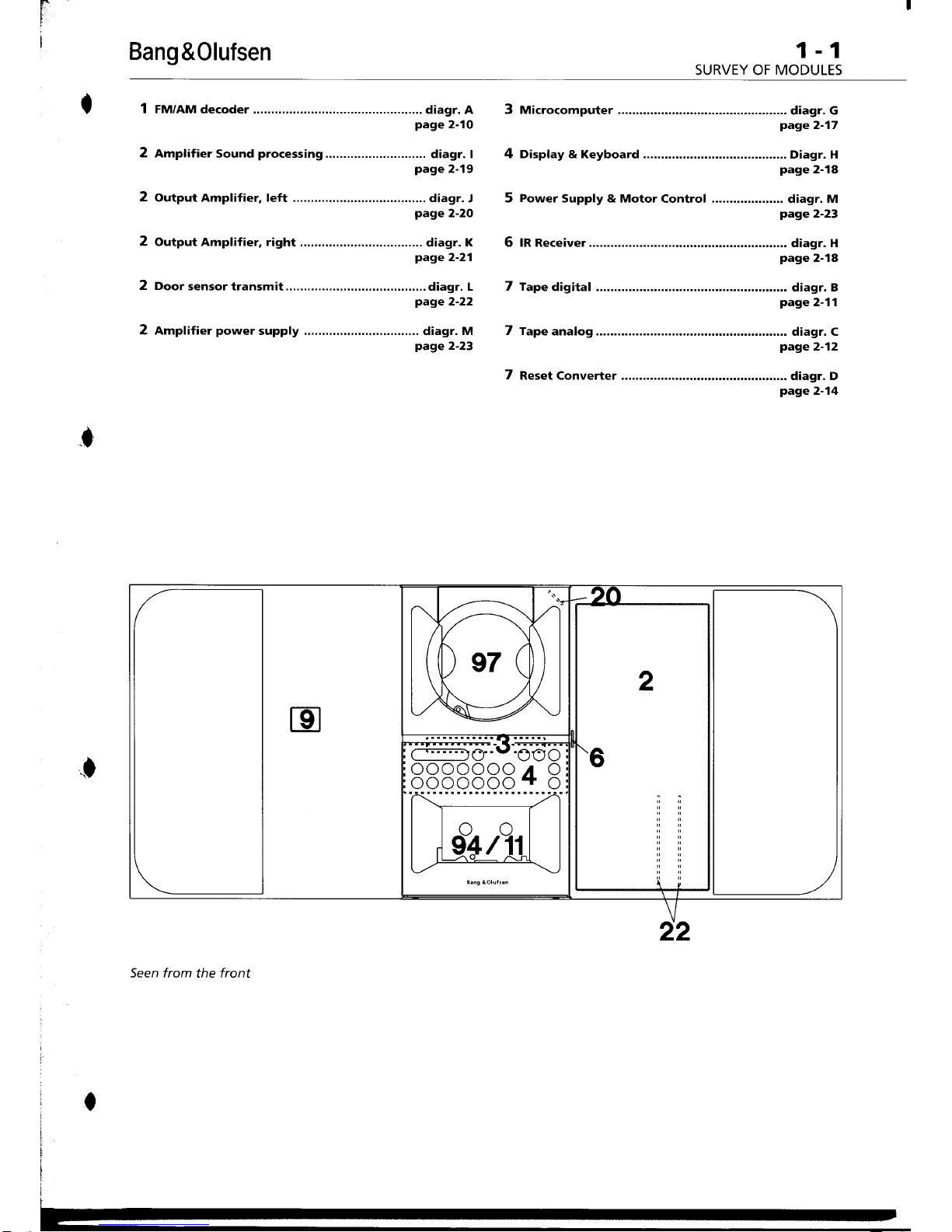
FM/AM
decoder
..... diagr. A
page
2-10
Amplifier
Sound
processing
.......
diagr. I
page
2-19
Output Amplifier, left ..............
.. diagr.
J
page
2-20
Output Amplifier, right
............ .
diagr.
K
page
2-21
2 Door
sensor transmit....
diagr. L
page
2-22
2 Amplifier
power
supply diagr. M
page
2-23
3 Microcomputer...........
;$:rr1;;
4 oisptay & Keyboard
;"rJ:rrl;l
5
Power
Supply & Motor
Control diagr, M
page
2-23
6 rR Receiver...................
;.T:rr1;l
7 rape
dieital
;#:rr:;?
7 tape
analos
;#?:;;
7
Reset converter
;$:T-r?
I
.f
Seen from
the
front
r
I
1-1
SURVEY OF
MODULES
1-1
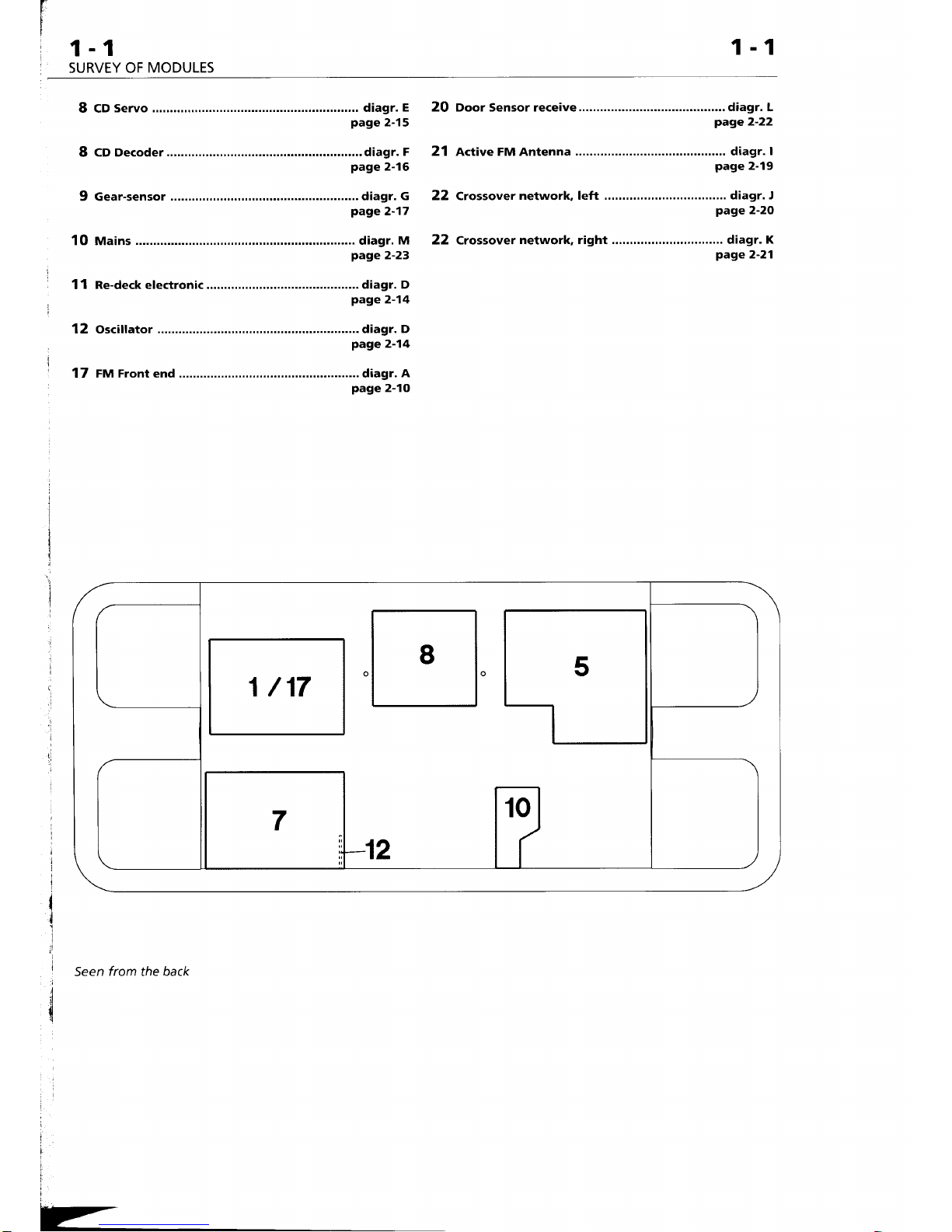
8 cD
servo
diagr.
E
page
2-15
8
CD Decoder
.................... ............. diagr.
F
page
2-16
9 Gear-sensor
................... diagr.
G
page
2-17
1o Mains
;:i'1tl-ii
11 Re_deck electronic
;$:T1?
12 Oscillator
................... diagr.
D
page
2-14
17 FM
Front
end
.
diagr.
A
page
2-10
Seen
from the back
2O ooor Sensor receive.........
..,...,,., diagr, L
page
2-22
21 active FM Antenna
diagr.
I
page
2-19
22 Crossover
network, left ...,,.,,.,,.,,
diagr. J
page
2-20
22 Crossover
network, right ......,..... diagr.
K
page
2-21
1/17
8
Z
1-2
1-2
SPECIFICATION
GUIDELINES
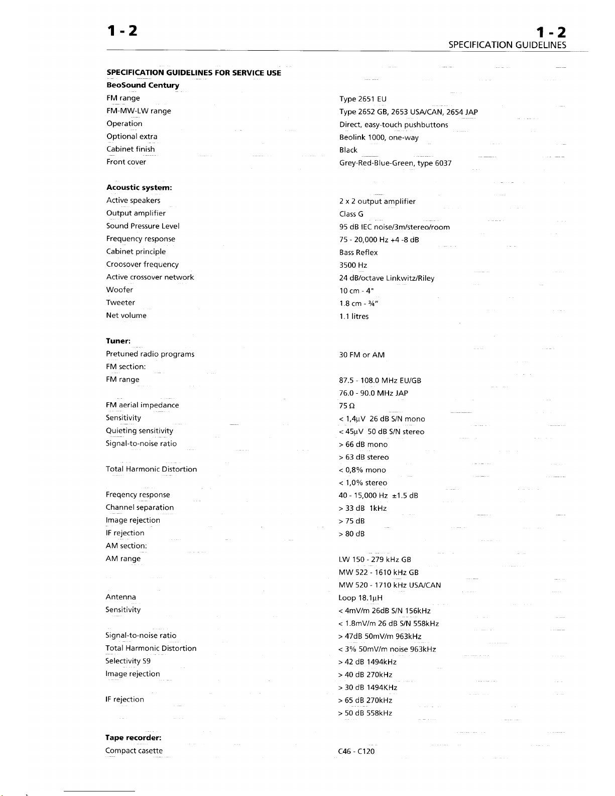
SPECIFICATION
GUIDELINES FOR
SERVICE USE
BeoSound
Century
rV ranfe
Type 2651
EU
FM-MW-LW
range
Type
2652
cB,
2653
USA/CAN, 2654
JAp
Operation
Direct,
easy-touch
pushbuttons
Optional
extra
Beolink
1000, one-way
Cabinet finish
Black
Front
cover
Grey-Red-Blue-Green,
type
6037
Acoustic
system:
Active
speakers
Output
amplifier
Sound Pressure Level
Frequency
response
Cabinet
principle
Croosover
frequency
Active
crossover network
Woofer
Tweeter
Net
volume
Tuner:
Tape recorder:
Compact
casette
PretuneJ radio
programs
30 FM
or AM
FM section:
FM range
87.5
-
't08.0
MHz
EU/GB
76.0 - 90.0 MHz
JAP
FM aerial impedance
75 O
Sensitivity
<
1,4;rV 26 dB
S/N mono
Qulgting
sensitivity
< 45prV
50 dB S/N stereo
Signal-to-noise ratio
>
66 dB mono
>
63 dB
stereo
Totai Harmonic
Distortion
<
0,8%o mono
< 1,0%o
stereo
Freqency
response
40 - I
5,000 Hz
+1.5
dB
Channel
separation
> 33 dB lkHz
lmage rejection
> 75 dB
lF rejection
>
80 dB
AM
section:
AM
range
LW
150
-279kHzGB
MW
522 - 1610 kHz GB
MW s20 tttOiiz
USA/CAN
Antenna
Loop
18.1prH
Sensitivity
<
4mV/m 26dB
S/N 156kHz
<
1.8mv/m 26
dB S/N 558kHz
Signal-to-noise ratio
>
47dB 50mV/r
gOitHt
Total Harmonic
Distortion
< 3% 50mV/m noise
96ikHz
Selectivity 59
>
42 dB 1494kHz
lmage
rejection
>
40 dB 270kHz
>
30 dB
1494KHz
lF rejection
>
65 dB 270kHz
>
50 dB 558kHz
2x2outputamplifier
Class G
95 dB IEC noise/3m/stereo/room
75 - 20,000
Hz +4
-8
dB
Bass Reflex
3500 Hz
24 dB/octave Linkwitz/Ri
ley
10cm-4"
1.8
cm
-
3/q"
1 .'l litres
c46
-
C120
-2
INES
1-2
SPECIFICATION
GUIDELINES
Bang
&Olufsen
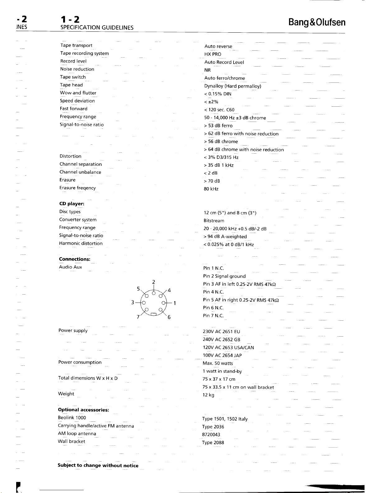
fape
transport
Auto reverse
Tape
recording
system
Record
level
Noise
reduction
rape
swttcn
fape
fread
Wow
and flutter
Speed deviation
Fast
forward
Frequency
range
sig;at
to-noise ratio
Distortion
Channel
separation
Channel
unbalance
Erasure
Erasure freqency
CD
player:
Drsc
type:
Converter
system
Frequency
range
Signal-to-noise
ratio
Harmonic
distortion
Connections:
nuOio
Aux
Power
supply
Power
consumption
fotaiOimensionrW"|{*O
Weight
HX PRO
Auto
Record
Level
NR
Auto
ferro/chrome
oynattoy
iHarO
permalloy)
<
0.15% DtN
<
+2o/o
< 120
sec.
C60
50 - 14,000
Hz
+3
dB chrome
>
53 dB ferro
t
62 ;B ferro
with noise
reduction
> 56
dB chrome
>
64 dB chrome
with
noise reduction
<
3oh D31315
Hz
>35dB1kHz
<2dB
>70dB
80 kHz
12 cm
(5")
and
8 cm
(3")
B itstrea
m
20
-
20,000 kHz
+0.5
dB/ 2 dB
>
94 dB
A-weighted
< O.025o/o
at
0 dB/1 kHz
Pin t
l.t.C.
Pin
2
Signal
ground
Pin 3 AF
in left
0.25-2V RM5
47kO
Pin 4 N.C.
Pin
5 AF in right
O.25-2V
RMS
47kO
Pin
6 N.C.
Pin 7 N.C.
230V AC
2651 EU
240V
AC 2652
GB
12OV AC
2653 USA/CAN
toovnc
2654
JAP
Max.
50 watts
t wati in
stand-by
75x37
x17
cm
75
x 33.5 x 11
cm on
wall bracket
Optional
accessories:
Beolink'1000
Carrying handle/active
FM
antenna
nfV
loop
antenna
Wall bracket
Subj-ct
to
change
without
notice
12 kg
Type
1501, 1502
ltaly
Type
2036
8720043
Type
2OaS
--
Bang
&0lufsen
wtRtNG
or
r*o*rrJ*tf,
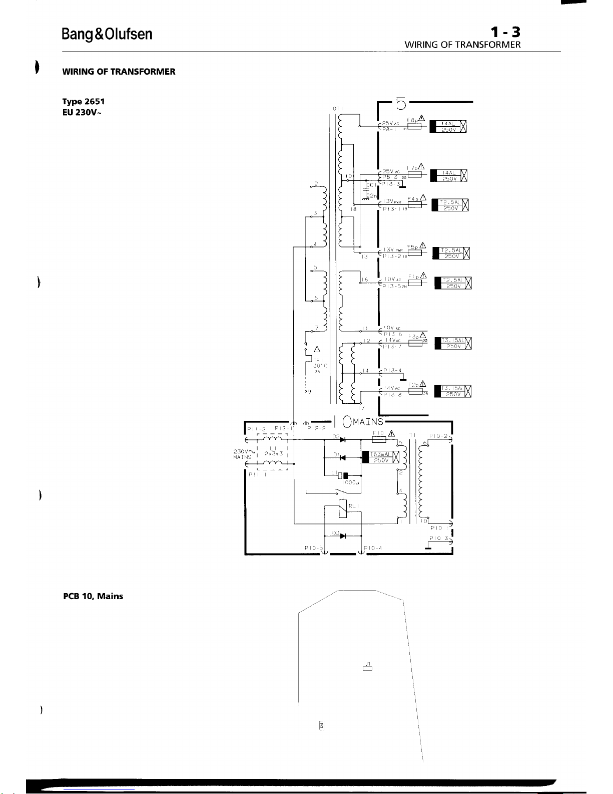
WIRING OF TRANSFORMER
Type 2551
EU 230V-
PCB 10, Mains
ffifr
ffiX
ffiil
ffiX
ffiil
ffiil
ffiil
.1
\
Qve,rN
1-3
WIRING OF
TRANSFORMER
1-3
ffim
ffiil
ffiil
ffiX
reil
Jl
1
II
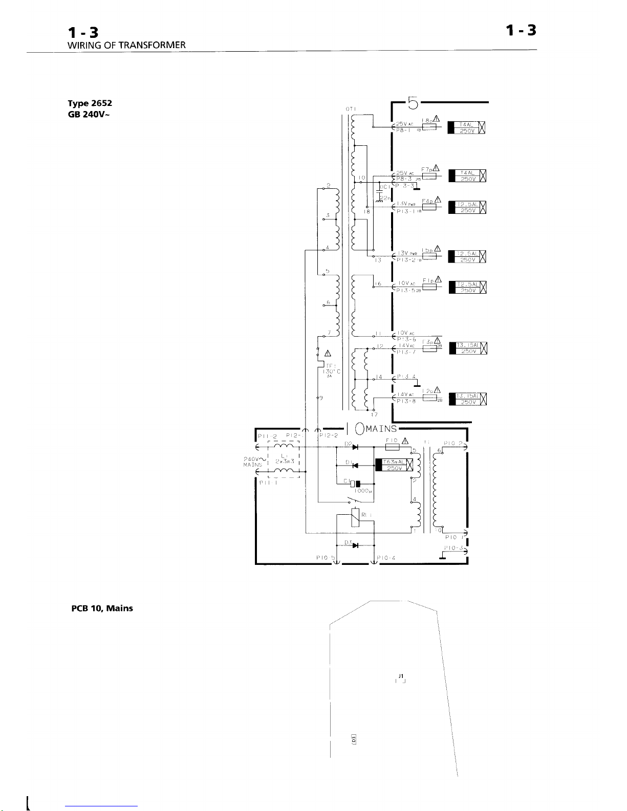
Type 2552
GB 24OV-
PCB
10, Mains
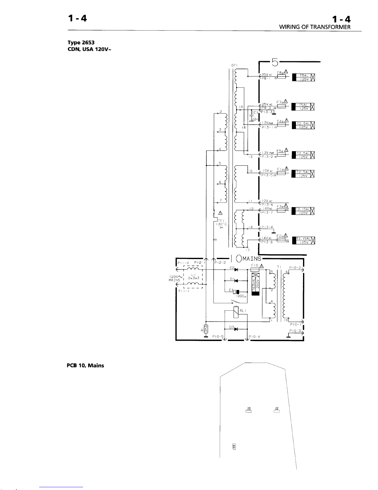
1-4
1-4
WIRING
OF TRANSFORMER
Type
2553
cDN,
USA 120V-
PCB 10,
Mains
ffiil
ffiil
-/_.-
"'I
g
3\
,\
l
QvnrNS
Bang
&Olufsen
1-5
BRIEF
OPERATION
GUIDE
1-!
BRIEF
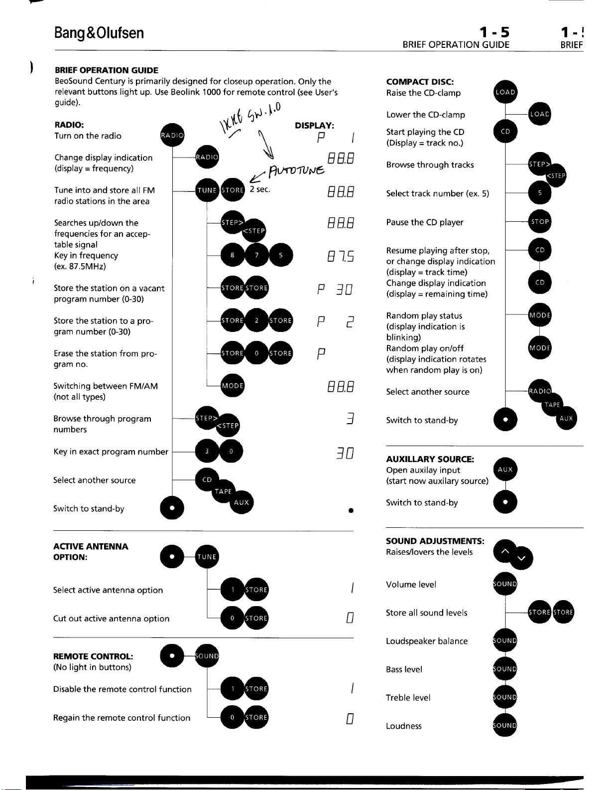
BRIEF
OPERATION GUIDE
BeoSound
Century is
primarily
designed for
closeup operation.
Only the
relevant
buttons light
up. Use Beolink'l 000for remote
control
(see
User's
guide).
RADIO:
Turn on
the
radio
Change display indication
(display
=
frequency)
Tune into
and store all FM
radio
stations in
the area
Searches
up/down
the
frequencies
for an
accep-
table signal
Key
in frequency
(ex.
87.5MHz)
Store the
station on a vacant
program
number
(0-30)
Store the station
to a
pro-
gram
number
(0-30)
Erase
the station from
pro-
gram
no.
Switching
between FM/AM
(not
all types)
Browse
through
program
numbers
Key in
exact
program
number
Select
another source
Switch
to stand-by
N
EE.E
Z"nffiflNe
2 sec.
EE.E
EE.E
E
1.5
P]D
E E.E
1
]D
COMPACT DISC:
Raise
the CD-clamp
Lower
the CD-clamp
Start
playing
the CD
(Display
=
track no.)
Browse
through tracks
Select track number
(ex.
5)
Pause
the CD
player
Resume
playing
after stop,
or change
display indication
(display =
track time)
Change display indication
(display
=
remaining
time)
Random
play
status
(display
indication
is
blinking)
Random
play
on/off
(display
indication rotates
when random
play
is
on)
Select
another source
Switch to stand-by
.,{,
1-''il'l'0
$ltu
'
DrspLAy:
\'//'
\
p
\F
E
P
P
AUXITLARY
SOURCE:
Open auxilay input
(start
now auxilary source)
Switch
to stand-by
ACTIVE
ANTENNA
OPTION:
Select active antenna
option
Cut out
active antenna option
D
SOUND ADJUSTMENTS:
Raises/lovers
the
levels
Volume level
Store all sound levels
Loudspeaker
balance
Bass level
Treble level
Loudness
REMOTE
CONTROL:
(No
light in buttons)
Disable
the remote
control
function
Regain
the remote control function
D
t-5
GUIDE
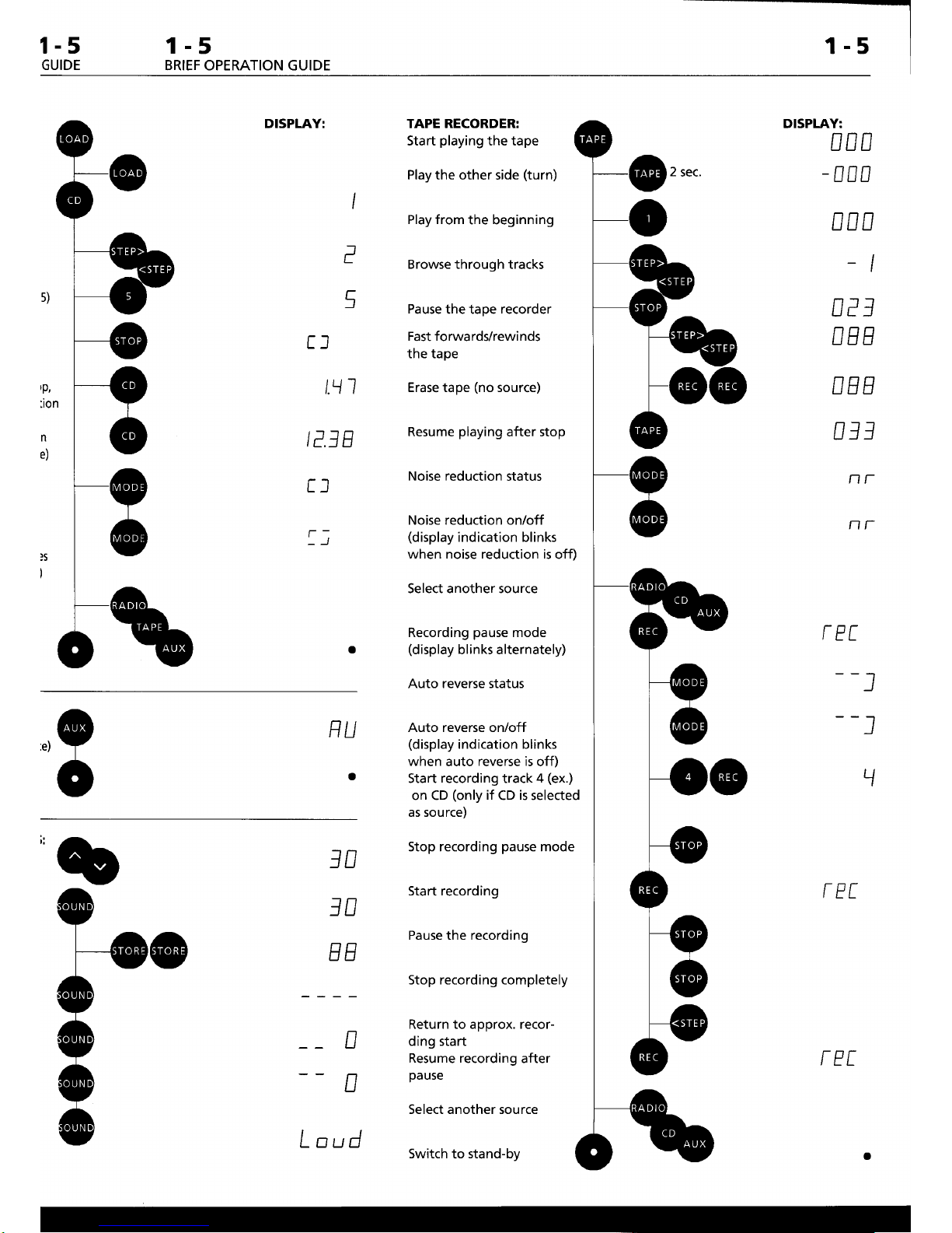
1-5
BRIEF OPERATION GUIDE
DISPLAY: TAPE RECORDER:
Start
playing
the tape
Play the
other side
(turn)
Play from
the beginning
Browse through tracks
Pause
the tape
recorder
Fast forwards/rewinds
the tape
Erase tape
(no
source)
Resume
playing
after stop
Noise reduction
status
Noise reduction on/off
(display
indication blinks
when noise reduction is
off)
Select another source
Recording
pause
mode
(display
blinks alternately)
Auto reverse status
Auto reverse onlofl
(display
indication blinks
when
auto
reverse is
off)
Start
recording
track
4
(ex.)
on CD
(only
if
CD
is
selected
as source)
Stop recording
pause
mode
Start recording
Pause the recording
Stop recording completely
Return to approx. recording start
Resume recording
after
pause
Select another source
Switch
to
stand-by
DISPLAY:
Dnn
-
nnn
NDD
I
I
nPl
DEE
DEE
DJl
nr-
NT
rEt
--l
--l
\
rPr
@r,"..
I
f
I
tl
t.\ 1
IE
lE
tl
ll
.,9
c
NU
a
1n
1D
EE
D
D
Lnud
rPr
Bang
&Olufsen
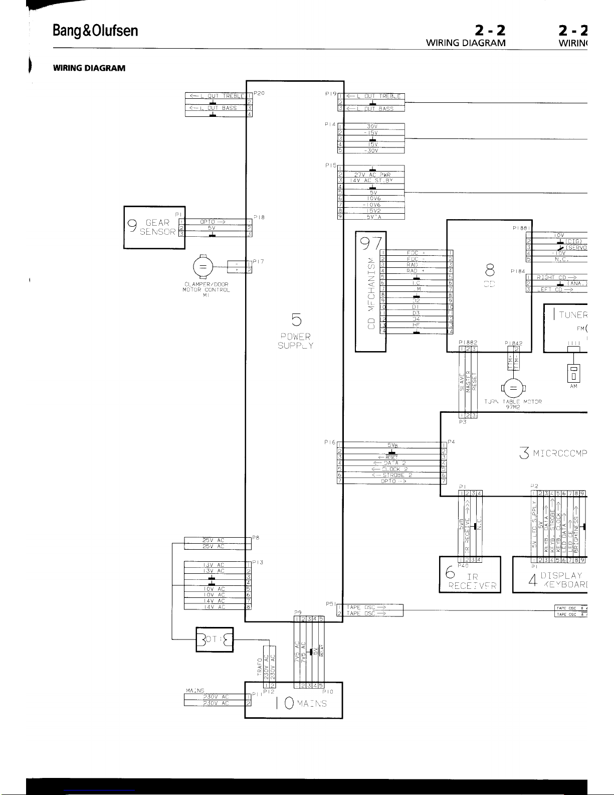
2-2
WIRING
DIAGRAM
2-2
WIRIN(
WIRING
DIAGRAM
5
D
[.]',! ER
SI..]PP.Y
A
GEAR
-/
llF l\saR
PE']I=.
V'
R
I Q
va,xs
CL A N1PFR,/
L-]OOR
MOTI]R
CONIRCL
M
TI.]A\
IABLF V:T3A
9lt/2
3
ricttttit\,tP
7
DISPTAY
+
(EVBI]ARI
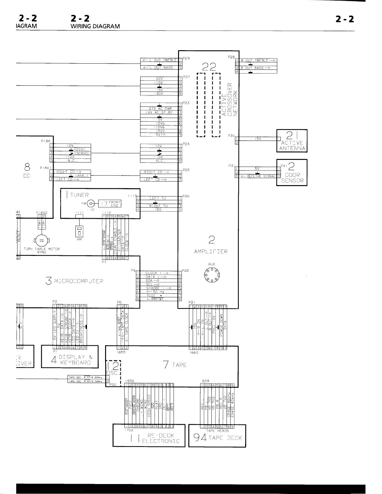
2-2
IAGRAM
2-2
WIRING DIAGRAM
2-2
(J
CD
?
I
VEi-
3,tct?o:rir4PJlfrr
r)
ra
ANlPL
1I- I IR
AUX
ANI [N\A
IVE 5IGNAL
TURN TABLE
I,1O-OR
91t!2
I
rlNrn
"@ffi
655
66c
Dl 7
.^D
I
t-!
SC "i
|
-_.
.-.. r :i:g-- J3:
I [r
az=
:t;-:,r,
2-3 2-3
BLOCK DIAGRAM
2-i
BLOC
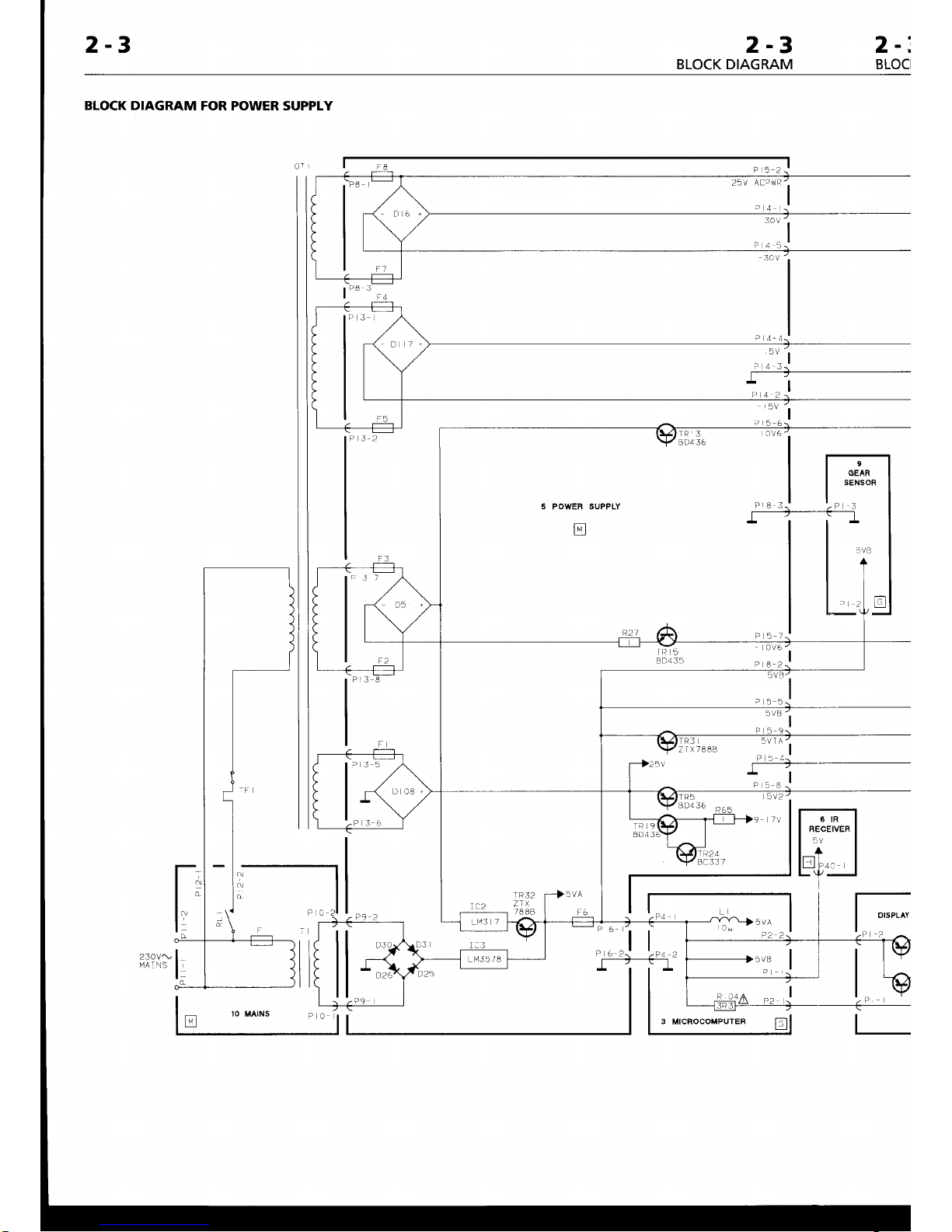
BLOCK DIAGRAM
FOR POWER SUPPLY
TR3
Z
TX7888
F
JBj?-
, , ;-!
rP32
r-t5vA
5VA
P2-2
230V!
I/A ] NS
2-3
)CK DIAGRAM
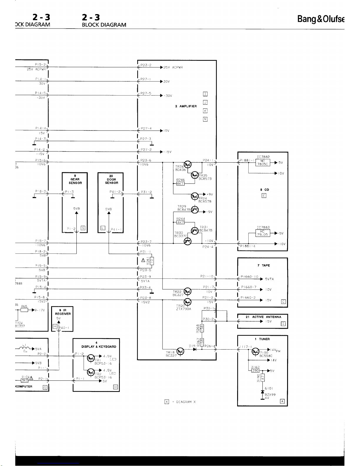
2-3
BLOCK DIAGRAM
Bang
&Olufse
r
"-l
P23-2
,a.t
t
j
r .D
. -
,:':j
t.,,,
,
3
36
sv
-_lt-_
:.
I
-r
t:
uui
l-r*
u
ov6'
o
u ,-l
ti-]
u
2 AMPLIFIER
tr
E
I
R29
BC84 7
R244
.
:":i
|
^s
R35
BCB5 7 B
P20
Pt66A
0
P2 '-l P166A /
or'
otr
-l
5V
P30 I
Ie22
BC32]
o
N
t
D 5d
TR8
BC32I
7 TAPE
5vB
-l
i:::;
-r-f---Hs
rv
t-
I
l
r?2t
B:33 7
6tR
RECEIVER
5V
t
|;]l
Lr_i
P4J
I
I
I TUNER
5VTA
l0v
,aal
1
BC558C
l-,,,
,
P4 2i
'.
p3
-2
r-l-----T----f-
l
r c 7882
88 r --frF-
--{lJi^ 1-r
.u
t:
[ffi;-------------]-
ov
,:i:l
L;:i
l-
o ..0
T-
4
DISPLAY & XEYBOARD
-a
-T@,;|'ool.,
|
'
BrPbr b
@"1.,
-
|
BCP53
6
--------
5V
4Vru
l
l4v
)V
99
tr
[
=
orrcneu x
Bang
&0lufsen
2-4
BLOCK DIAGRAM
2-
BLO
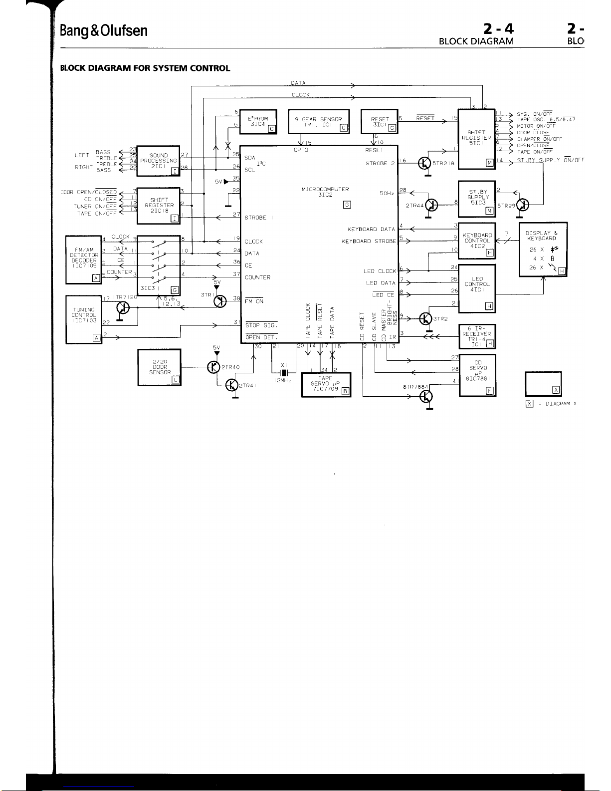
BLOCK DIAGRAM FOR
SYSTEM CONTROL
RAq<
TRFBI F
TDtrRI tr
toon
opEt,rcrosto
CD ON,/OFF
rurrR
0N/lII
IAPE ON,/OFF
SYS. ON/OFF
TAPE oSC. &5/8.41
MOTOR ON/OFF
DOOR
CLOSE
CLAMPER
ON,/OFF
OPEN,/C L OSt
TAPE ON/OFF
Cu^'lZOf
r
tr
DIACRAI'l
)
OPTO
RESET
SDA
I'C
STROBE 2
SCL
l'41CROCOI'.1PUTER
3IC2
SOHz
rn
Lll
STROBE
CLOCK
DATA
CE
COI,JNT ER
FM ON
STOP SIG.
KEYBOARD DATA
KEYBOARD STROBE
LED CLOCK
LED DATA
-lir<r
O
fo
F
L =Oc.
I
lu
o l& o
Ui
-<6*\
u u u
P ; S-.-
nn
U I
IK
5TR2 I 8
SH]FT
REG I S TER
2rc 8
DISPLAY
&
KEYBOARD
26x
f,
4x
B
F M,/AM
DE
TEC TOR
DECODER
IC7
05
3IC3
|
6 IR-
RECE ]
VER
TR 4-
8TR
7884
TAPE
SERVO
!P
1
IC]1
09
-4
RAM
2-4
BLOCK DIAGRAM
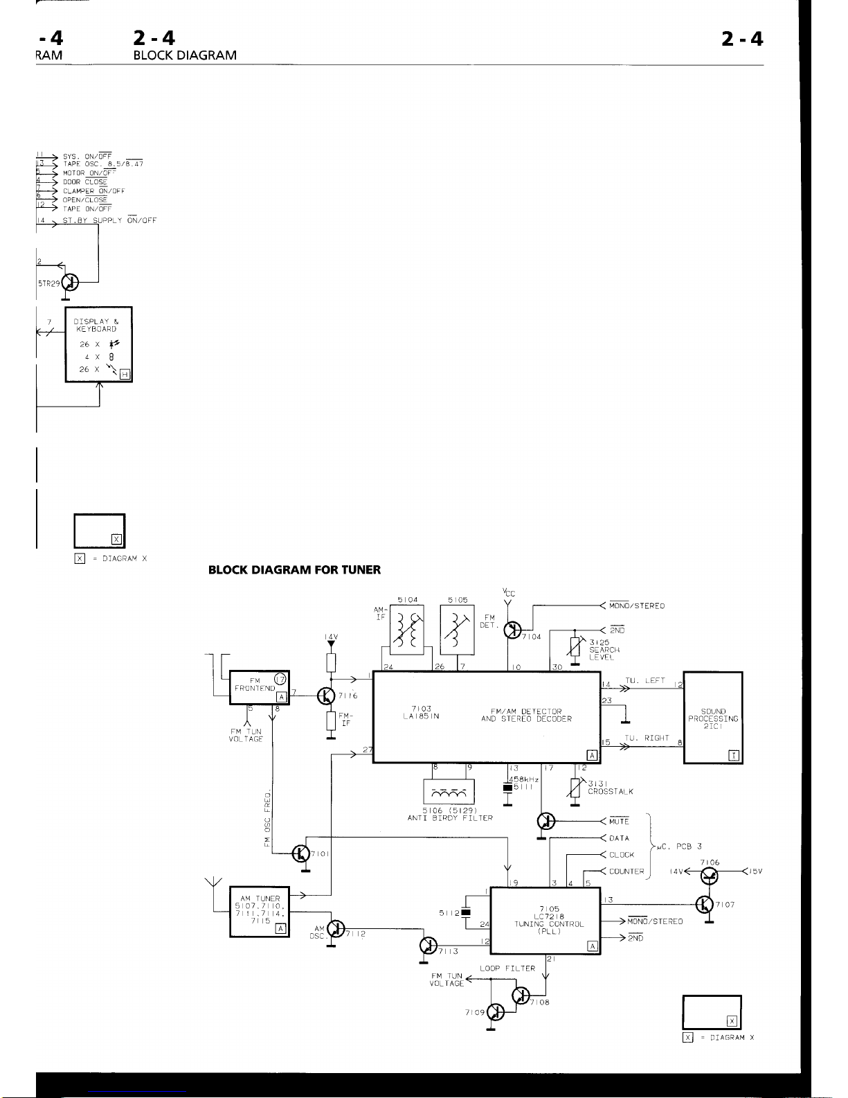
2-4
4-->
srs. onzorr
[-JJ
TAPE
oSC . 8. 5
/8
. 47
MOTOR
ON/OJ:DOOR CLOSE
CLAI.4PER ON,/OFF
OPEN / CL OSE
TAPE ON/OFF
ON,/OFF
tr
DIAGRAI'4 X
BLOCK DIAGRAM FOR TUNER
FM TUN
VOL T AGF
o
2
t"tOttOZSf
f nf O
2ND
3125
SEARCH
LE VEL
TU. LEFT
3r3
CROS
5t06
(5r291
ANT]
BIRDY FILTER
13
MONo-,/STEREO
2ND-
PCB 3
f t06
ST ALK
MUT EDAT A
CLOCK
COUNTER
1".
t4
FM TUN
VOL
TAGE
DISPLAY
&
KE YB OARD
zax
p
4x
I
F RON I
FND
.- -0_3 .
M
AV
DL I LL IOP
^
6. \
A\D
5I RLo DLCODER
5
2I
AM TUNER
5 07./ 0,
I |
./
4,
7l 5
_
ljl
705
LC12 8
TUN]NG CONTROL
(PLL)
LOOP FILTER
[
=
oracnau
x
2-5
2-5
BLOCK
DIAGRAM
2-
BLO(
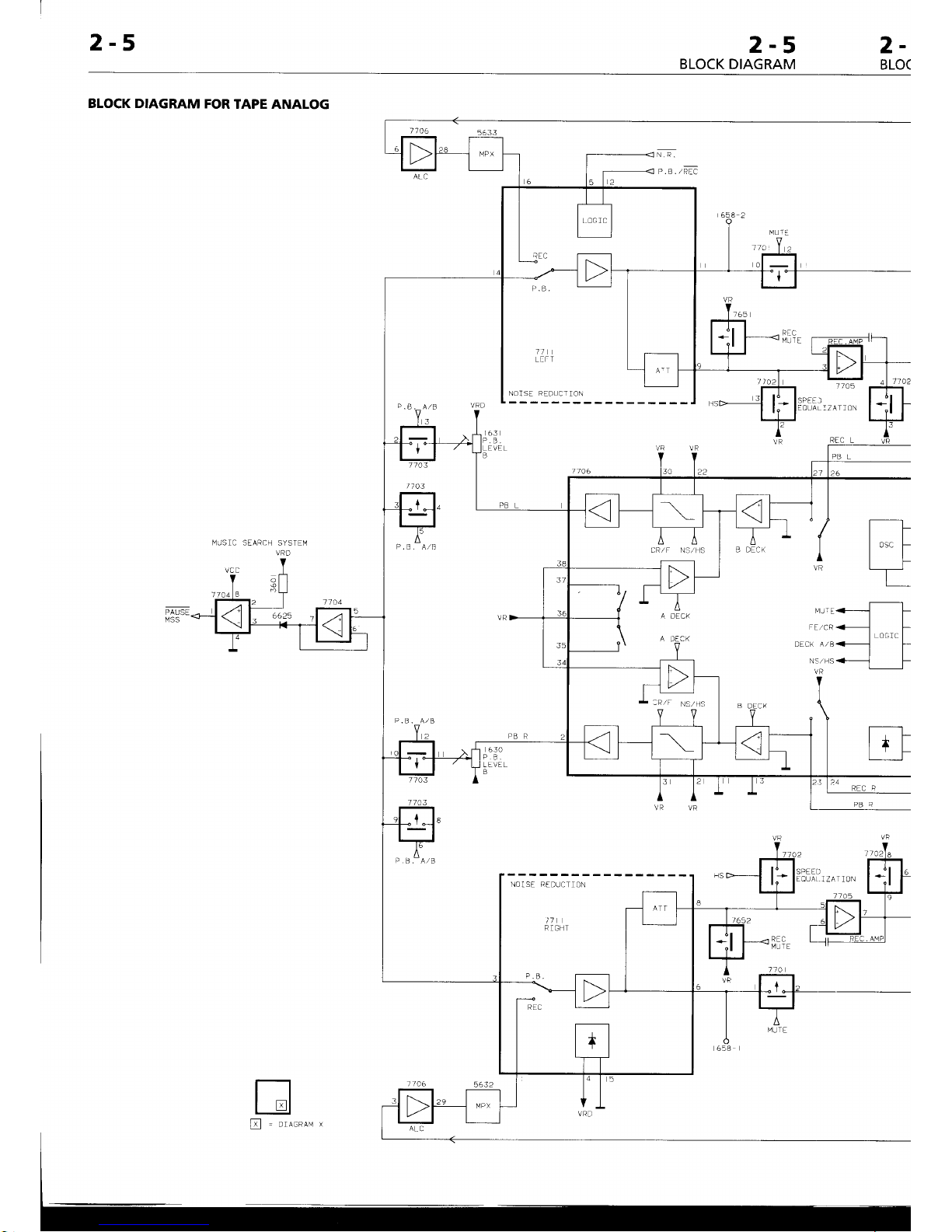
N.R.
p.
e .
zREC
BLOCK DIAGRAM
FOR
TAPE ANALOG
Rtc
MUTE
t/
LITT
NOISE REL]!CIION
NOlSE REDUCTION
t1
RIGHT
VR
22
3
2
VR
VR
I'lLr
I
E
FElCR
DECK A/B
NS/ NS
VR
VR
V
I
l3o
[t
lo"f
lf
L
'--[l-
F
I
LOGrc
I
r
'+---
J
[]
l+l
f
PAUSE
MSS
B DE'K
VR
63A
P.B.
LLVEL
B
REC R
PBA
P.ll.-AlB
[
=
orncnnv x
1l a6
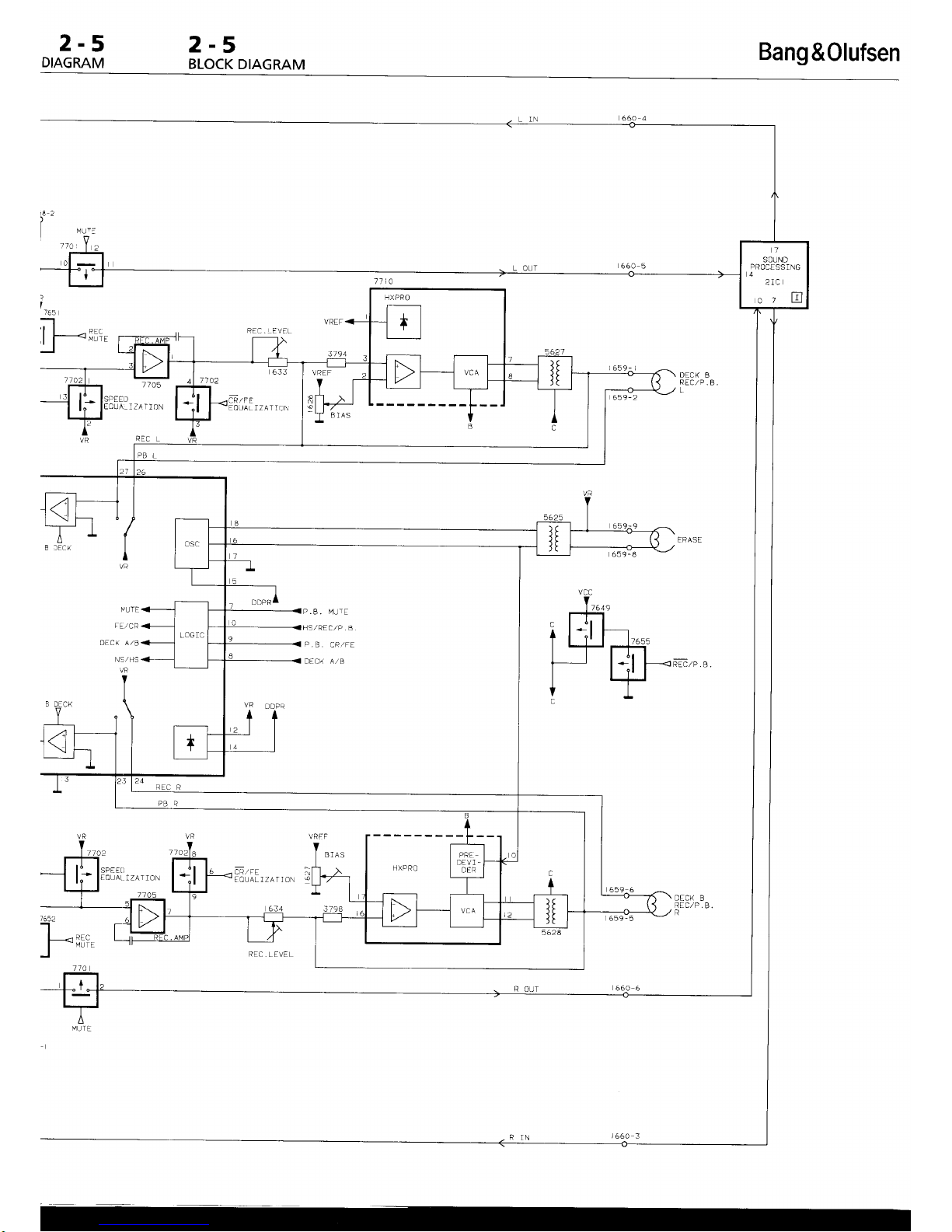
2-5
DIAGRAM
2-5
BLOCK
DIAGRAM
Bang
&0lufsen
i
765
;l atr.
I f-------<
vrir
-t
DECK
8
REC,/P.
B
/IA5
ED
EOUA-IZATION
REC
L
DECK
B
REC,/P ,
B.
a
IZATION
P .8
. MUTE
iang
&0lufsen
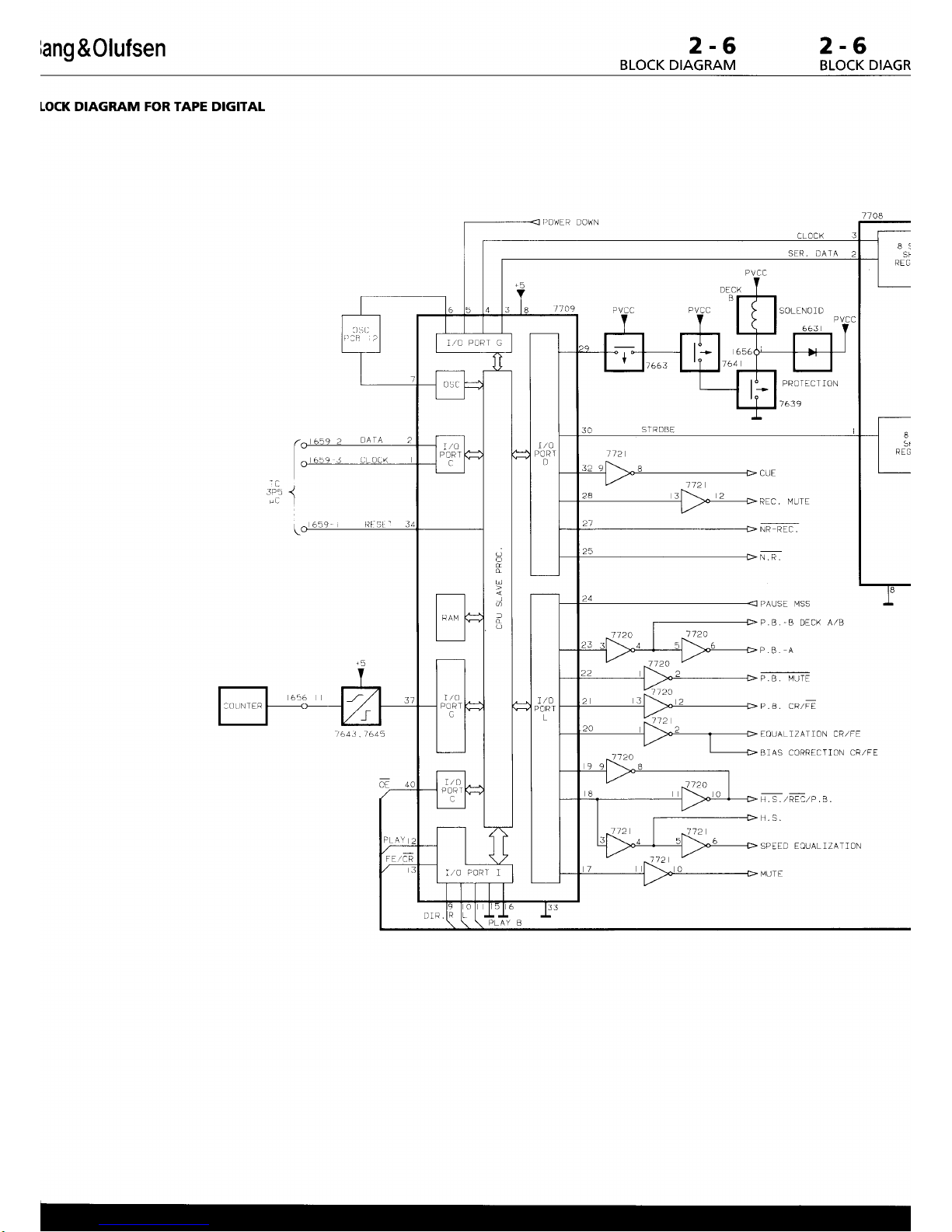
2-6
BLOCK DIAGRAM
2-6
BLOCK
DIAGR
LOCK DIAGRAM FOR TAPE DIGITAL
I]OWER
DO14N
8l
SF
REG
,
-T!
1
L]ATA
/643. /645
CUE
REC. MUTE
N.R.
112
E
St
REG
112
772A
ff20
112
PAUSE MSS
P,B,'B
DECK
A,/B
P,B. A
P.
B.
MTJTE
p.
s. cnzFE
EOUALIZATION CR,/FE
BIAS CORRECTION
CR,/FE
H.S.
SPEED EIUALIZATION
MUT E
,le
-0"
o\L
I > l5or
\OtD
i,/C
POR I
G
o
d
6
f
d
.Ot]NTFR
t,/0 P0Rt t
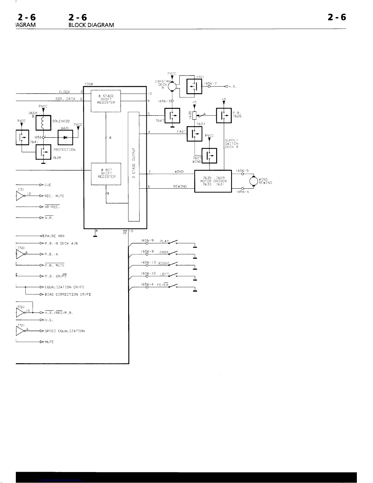
2-6
IAGRAM
2-6
BLOCK
DIAGRAM
2-6
DECK
0
9
SER.
DATA
_--_____________
cuE
112
f'- 2
I HRE[.
MUTE
l,/'
---------->
rrtn-nEc.
----------------
N. n.
----------------
PAUSE l'4SS
#P.8.
B DECK A/B
712A
t|)xo->c.a
-e
#P.B- lVtlTF
,-
-P.8. CR,/FF
P.B.
1 625
WIND
REl,
] ND
-a
cAS
-4
FE/cR
-------t*------t
------.1
-------t-
-------t-
EOUALIZATlON CR,/FE
BIAS
CORRECTION CR,/FE
_-_-_-_________>
H.S
{2
,t'---+
spr I D I oLA_ t./A--o\
+MUTE
f
L
-
O
U
O
D
2-7
2-7
BLOCK DIAGRAM
2"'
BLOCI
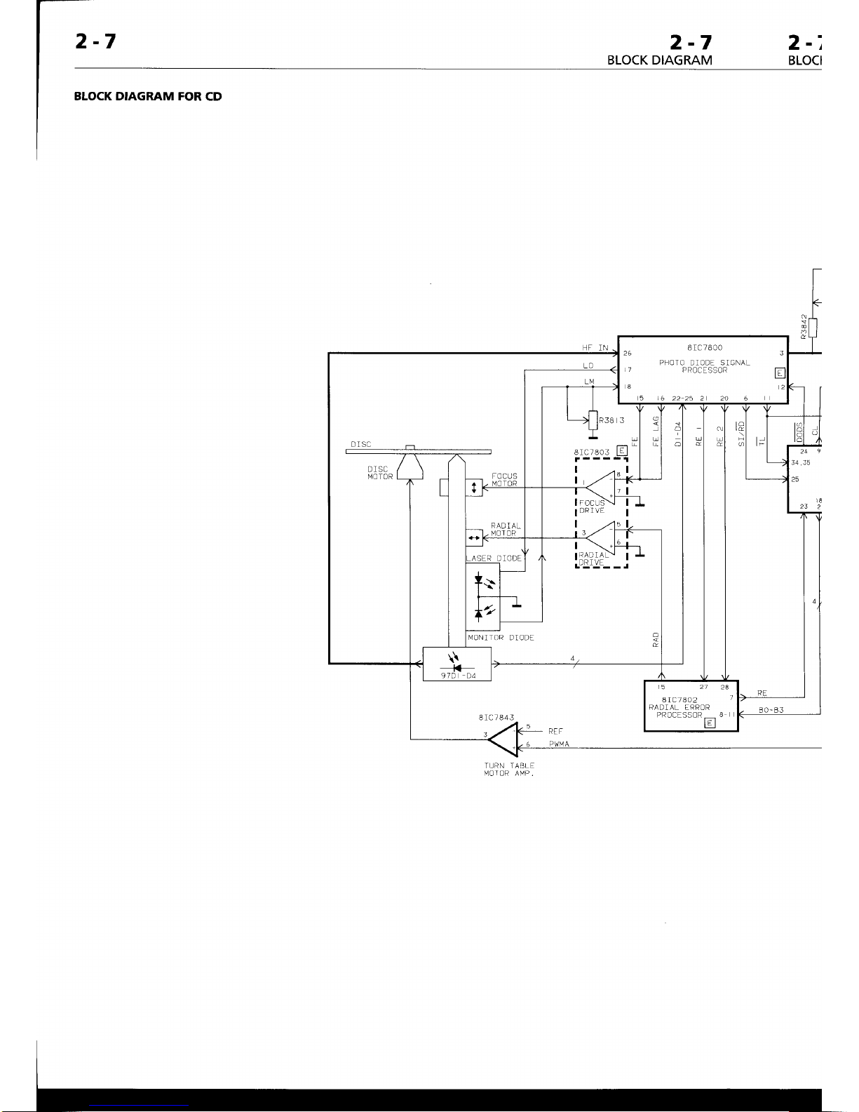
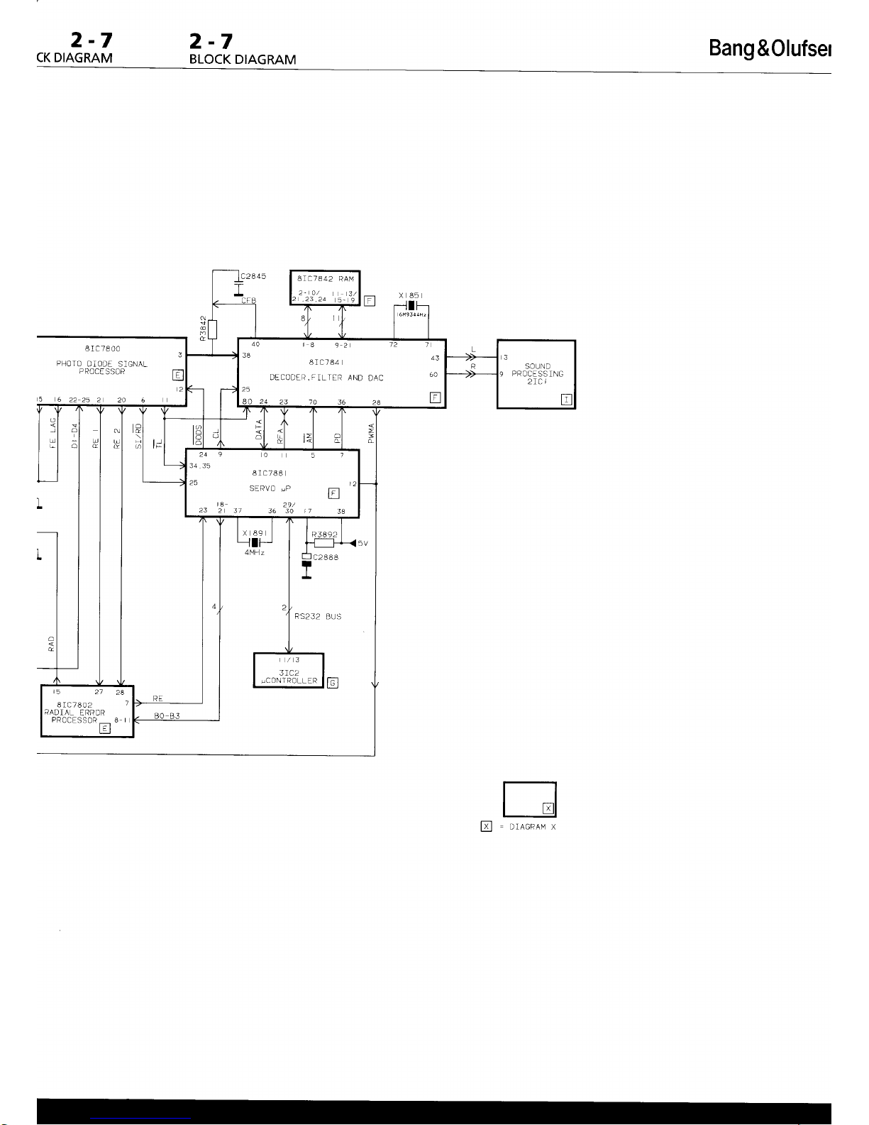
BLOCK DIAGRAM FOR
CD
I r c7800
PHOTO DIODE SIGNAL
P ROCE
SSOR
!_l!c
_
D]SC
MOTOR
arcrsos
lll
|
,.,u
I
I
DRIVE
r
x3?,1f
'-
r
L"]-':-- - J
NlONITOR
DIODE
8 I C7402
RADIAL
ERROR
PROCESSOR
_
H
8rc7843
f
TURN TABLE
NlOTOR AMP.
2-7
CK DIAGRAM
2-7
BLOCK
DIAGRAM
Bang
&Olufsel
8IC7842
RAt'1
2- A/
3/
.23.24
5- 9
40
|
8
9
2
l2
f
38
8rc784
DECoDER,FILTER
AND
DAc
60
25
249051
Brc788
25
SERVO
!P
tr
ta
29/
23
2 3f
36 30 t7
38
/3
uCONTR0LL
ER
8 r c7802
RADIAL
ERROR
8IC7800
PHOTO
DiODE SIGNAL
P
RCCE
SSOR
6
2225 2
2A 5
RS232
BUS
 Loading...