

Bang & Olufsen 1721, 1723, 1722, 1724, 1725 System Manual
BatU&0uberl
BEOLAE
150, TWE
L721" L722, L723,1724,1725
II{DHOLD
Diagrammer ...:...
. 4-48
Halvlederoversigt .
.. 4-50
Elektrisk styHiste
..
4-52
Mekanisk styHiste
..
4-54
Justeringer
... 4-57
Tekniske specifikationer
.. .. ......
4-57
Servicetips
... 4-58
Isolationstest .....
.. 4-61
4-48
CONIENTS
Circuit diagrams
Semi-conductorsi
....
List of electrical
parts
.
List of mechanical
parts
.
Adjustnents
Technical specifications
....
Service tips
..
....... 4-58
Insulation test ..
....
4-61
4-48
4-50
4-52
4-54
4-57
4-57
DIAGMIT{FORTU$ING
Pi
diagrammet
er der angivet typenumre
pi
transi-
storer og IC'er i de tilfelde
hvor typenummeret er
entydrgt for komponenters
placering
i kredslobet
-
f,eks. TR20/BC 5578
Hvis
positionsnummeret
er efterfulgt af en stjerne
skal
reservedelsnummeret benyttes, da denne
komponent er specielt
udvalgt - f.eks. TR1021
Koordinatsptem
De stsrste
printplader
er forsynet med et koordinat-
system.
Komponenterne
pl
disse
printplader
er
pA
diagrammet
forslmet med en koordinatbetegnelse,
som forteller i hvilket felt
pi printpladen
de er
placeret
(mindre
skrifftype end
positionsnummeret
-
f.eks. B3).
kdningsfoftindels€r
Ledningsforbindelser
pi
diagrammet er samlet
i
"bundter*.
De enkelte ledninger er
forsynet med
koder,
der fortaller hvortil de
gtr.
INTERN FORBINDELSE
PA EN DTAGMMSIDE
E)(PIITNATION OF DIAGRAM
Type numbers of transistors
and IC's have been
indicated
on the
diagram in those cases
where the
type number
is unambiguous for the
position
of the
component in a circuitry - e.g. TR20/BC 5578.
If the
position
number
is followed by an asterisk the
spare
part
number must
be
used because this
component has been expecially"selected
-
e.g.
TR102*.
System
of
Co-ordinates
The largest PC-boards
have been
provided
with a co-
ordinate system.
The components on these PC-boards
are
provided
with
a
grid
reference on the diagram
indicating in what
gnd
they are
positioned
on the PG
board
(smaller
typing than
position
numbers - e.g.
B3).
Wiring C.onnections
The wiring connections
on the diagram are
assembled
in
"bundles".
The individual
wires are
coded to
indicate
to
where they are leading.
INTERNAL CONNECTION
ON ONE
DIAGMM PAGE
Internal connections on a
diagram
page
are
indicated by a number. The bend of the
wire indicates
in which direction the other end of the
wire mav be
found.
llrl
1220n1n
\\//
Interne forbindelser
pi
en diagramside angives
med
et tal. Knakket
pl
ledningen
viser i hvilken retning
den anden ende af
ledningen findes.
4-48
Forsyningsspeqdingetr
Supply Voltage
En
pil
og spandingen viser, hvor forsyningsspendiq- An
arrow and the
voltage
show
where
the
supply
gerne gfr
ind i
et
prinl
voltages are fed to a PCB.
Eksempel:
(7
CON.) feks. ved
siden af
forsynings- Example:
(7
CON.) next to the supply
voltage
spendingen angiver det antal stedet, spandingen
gtr
indicates the number of
places
where
to
find
the
ind
pi
denne diagramside. voltages in this diagram.
Symbol for sikkerhedskomponenter
for Safety Components
Ved
udskiftrting af komponenter med
dette symbol
When replacing
components with this symbol compo-
skal der anvends komponenter med samme reserve- nents with identical
part
numbers are to be used.
delsnummer. Den nye komponent skal monteres
pi
The new
component must be fitted in the same way
samme mtde som
den udskiftede. as the one replaced
uArJBBrnqCBrsBn
MEAST'RING
coNDITIoNS
Alle DC spandinger er milt i forhold
til stel,
All
DC
voltages
have been measured in relation
to
med voltrneter med
en indgangsmodstand
pA ground
with voltneter with
an input resistance of
10 Mohm.
10 Mohms.
Spendingerne er milt uden signaltilforing. The voltages have been measured without
any supply
of signal.
\
4-48
d-
4-49
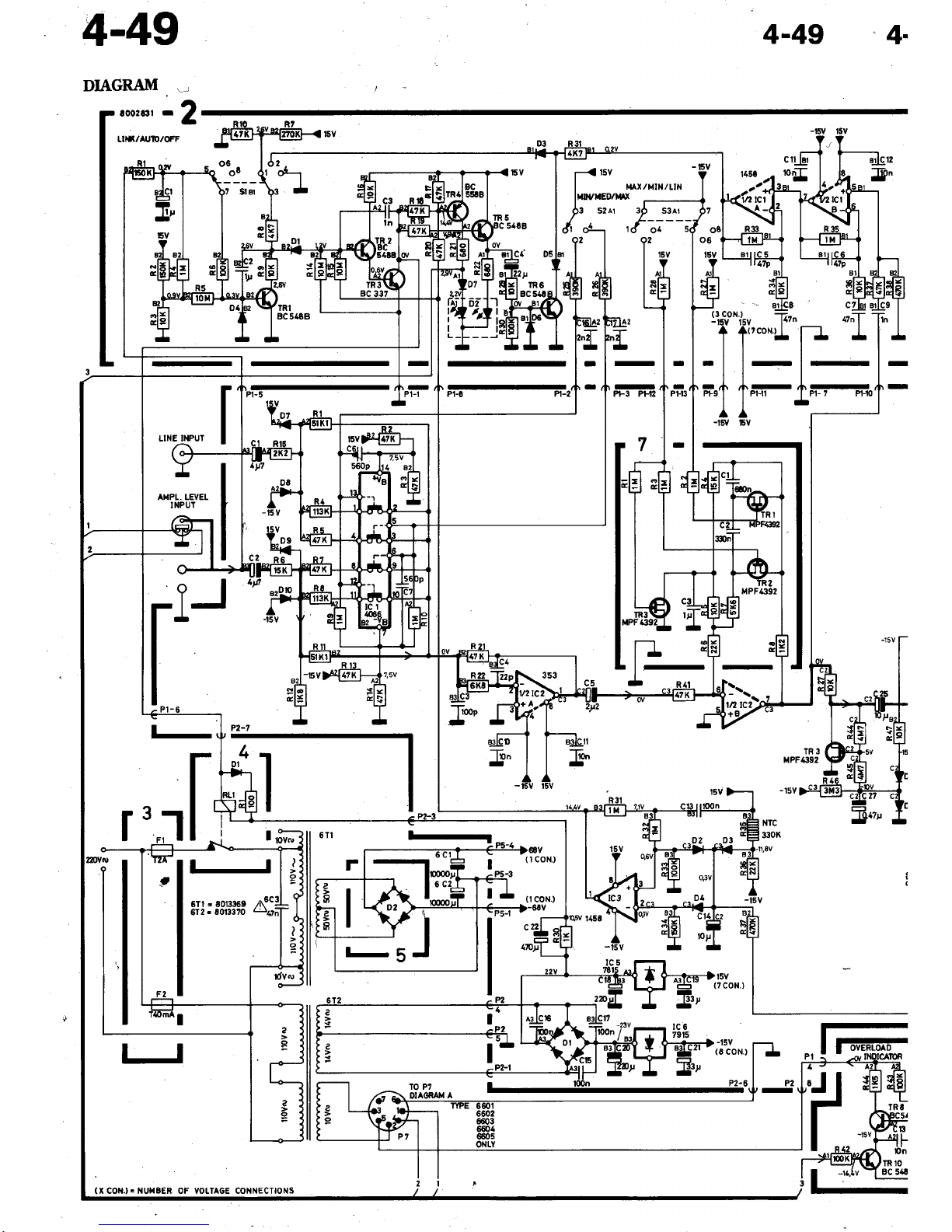
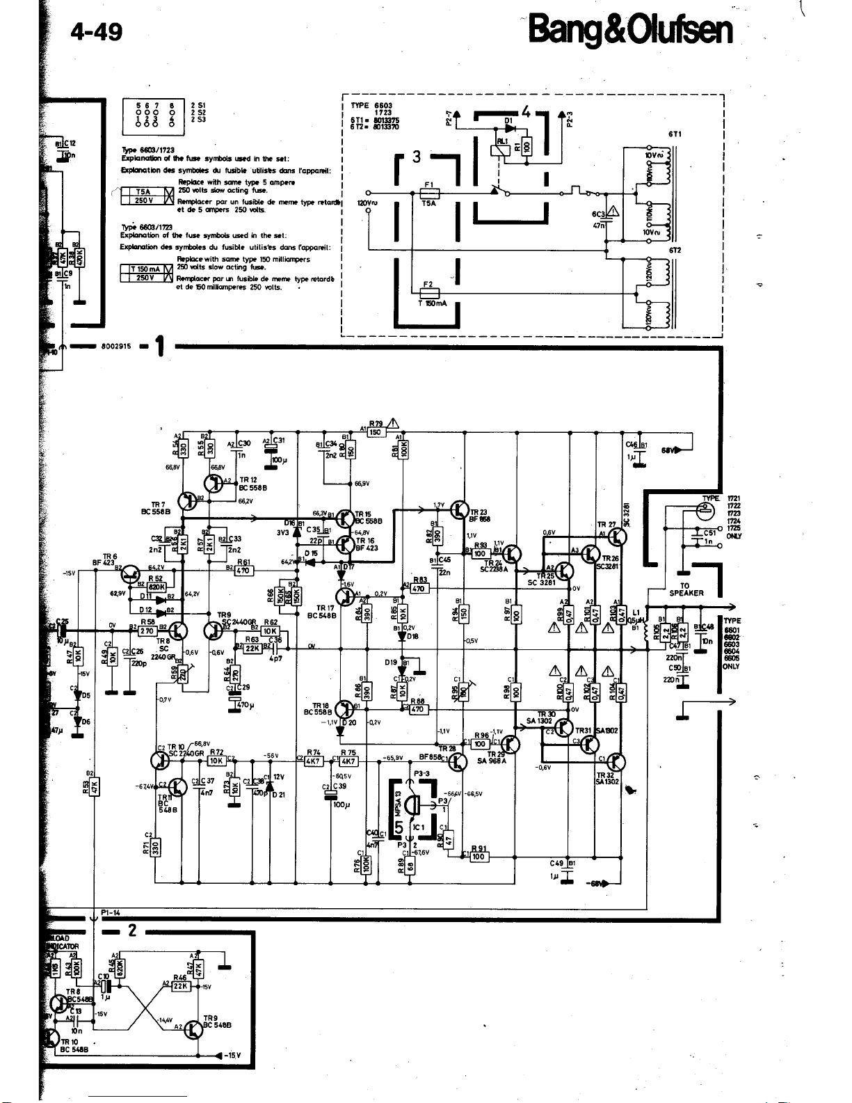
DIAGMM
!]
4-49
-4.
r
t002&il
r
Lm(/AUII!/OFF
3
o6
oE
)t SlBr
cZtsl
n
nzn-f
fr4
I
l-
I
/i\--
I
Pl- 7 Pr-1
-
(3coN.)
i-
-l6V
l5V t'
T 1.'*-.*
-ll-
r/r
A-
*r
l I
Pr-r'
A
-lsv
6v
I
I
P|.t3
I
'tsv
(7
CON.)
-t5v
(6
CON.)
?2-6
E-
a-
-
-
PF3 PFN
]7
l'''
P2-7
-
4
t-
JI
I
-'.-
I
;v'
I
['
t0
-{
tsv
I
r,tAx/MtN/uN
IuLl€D/t{rx
I l--
P3
szAr
3P
S3Al
{'
*
,{.u--
l5v
l-llJ
t9
6Tl . E013359
612
r
8013370
LINE II{PUT
(r
t
A}IPL. LEVEL
INPUT
l-
I f
-[lv
J
BC 51t
iT
,_
4-49
Baru&OuHt
[--E:
s--l
z sr
I
ooo
o t2s2
|
66t 6
|
zsr
Ilfr
5S/1723
EtPbnqtlon oa lho ts ryn$ob
ed h thG st:
E
dmlbn
dc
synldcs dr tudbb utilirts dqm l'qppoEil:
w9rffi/|ta
ErpbElion of lht
le
iynbols @d h thc et:
Expbmiin d6
sy[$olrs du tusibl. utili3bs
dc foppqFil:
Rtpbcc with $m
type l5O mitliqrpe.s
250 Elts 3low
eihg fts.
RcmCcr
pqr
h tusilt
de mm typ.
rets.d!
et
de !5otrilloD€E
250 wlb.
lR7
8C
5584
fr2l
fln
fln
.ITA
1t?5
oity
ffi$'|Ht
;H'
l*"
l"
Bang&0uHt
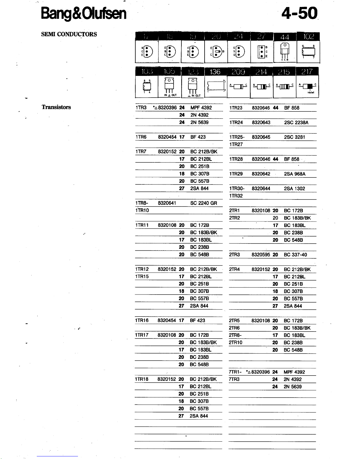
SEITfi COITDUCTORS
Transistors
4-50
1TR3 %8320396 24
MPF 4392 1TR23 8320646
t$4
BF 858
24
2N
4392
24
2N 5639 1TR24
8320643 2SC 2238A
1TR6
832%il 17 BF 423 1TR25-
8320645 2SC 3281
1TR27
1TR7
8320152 20 BC212B|BK
17
BC212BL 1TR28 8320646
tt4
BF 858
.
20 BC
2518
18
BC 3078 1TR29
2SA 968A
20 BC
5578
27 2SA
844
1TR30-
2SA 1302
1TR32
1TR8-
8320641 sc 2240
GR
lTRlO
8320108 20 BC 1728
2TR2
20 BC 1838/BK
lTR1l
8320108 20 BC1728
17 BC 1838L
M BC
1838/BK
20
BC 2388
17 BC 18381
20
BC 5488
20
BC 2388
20 BC
5488 2TR3 8320595 20 BC
337-40
1TR12
8320152 20 BC212B/BK 2TR4
832U52 m BC
?|AB/BK
1TR15
17
BC212BL 17
BC212BL
20 BC 2518
20 BC
2518
18 BC 3078
18 BC 3078
m
Bc557B
20
BC 5578
27 2SA
844 27
2SA 844
1TR16
8320454
17
BF 423 2TR5
8320108 20 BC 1728
2TR6
M BC 183B/BK
1TR17
8320108 20 BC1728. 2TR8-
17 BC 1838L
20 BC 183B/BK 2TR1O
m
Bc238B
17
BC 183BL
20 BC 5488
m Bc238B
20 BC 5488
7TR1-
'a8320396
24 MPF4392
1TR18
8320152
20
BC2lzBtBK 24
2N 4392
17 rc212B,L
20 BC 2518
18 BC
3078
m
Bc
5578
8320642
8320644
2TR1
27
2SA 844
7TR3
24 2N
5639
 Loading...