

Page 1
防静电电焊台系列
Anti-static
Soldering station series
936/937/939/928
感谢您购买此款电焊台,本产品是专门为 无铅 拆焊 而设 计的 ,使 用前 请仔 细阅 读本 说明 书,
阅读后请妥善保管,以供日后参考。
Tha nk you f or p urcha si ng t hi s so ld ering stati on , th is p ro du ct i s sp ecial ly d es ig ne d fo r le ad-free
sol derin g, plea se read t he inst ructi on s ca re fully bef or e us e. Af ter rea d, p le as e keep it for f ut ur e
ref erenc e.
中文(繁)/English
声明:本公司保留改进升级产品的权利, 产品 规格 及设 计如 有变 更, 恕不 另行 告知 。
Statemen t: The company reser ve s th e ri gh t to i mp ro ve a nd u pg ra de p ro du cts,
product sp ec ifi ca ti on s an d de si gn a re s ub je ct t o ch ange without noti ce .
INSTRUCTION MANUAL
使用说明书
Page 2
1
使用本机器,下列基本措施要遵守,以免 触电 或对 人体 造成 伤害 ,避 免火 灾
等现象的危害。
1、为了确保人身安全,该机器工作完毕后 请关 闭机 器右 侧的 总开 关, 如长 期不
使用,请拔掉电源线!!!
2、必须使用原厂认可或推荐的零件,否则 将导 致严 重后 果。
3、机器故障必须由专业人士或本公司指定 人员 进行 维修 。
4、本产品使用三线接地插头,必须插入三 孔接 地插 座内 ,不 要更 改插 头或 使用
未接地三头适配器而使接地不良。
5、电焊台开启后,其温度都有可能达到400度以 上。 切勿 在易 燃、 易爆 气体 、
物体附近使用。切勿触摸烙铁金属部 分, 谨防 烫伤 。
6、电焊台开启后切勿离开工作岗位。
7、安装或更换烙铁部件时,必须在关闭电 焊台 后进 行, 必须 在烙 铁冷 却后 方可
进行安装或更换。。
8、使用后,切记要冷却机身,方可进行包 装。
9、切勿使用烙铁进行焊接以外的工作;切 勿用 烙铁 敲击 工作 台面 以清 除焊 剂
残余,此举可能严重损坏烙铁。
10、焊接时会冒烟雾,请做好应有的通风设施 。
安全守则
一、焊铁头的维护和使用
2
温度过高会减弱烙铁头功能,因此应选择 尽可 能低 的使 用温 度。 此
烙铁头的温度恢复力优良,较低温度也可 充电 焊接 ,可 保护 对温 度
敏感的元件。
应定期使用清洁海绵清理烙铁头,焊接后 ,烙 铁头 的残 余焊 剂所 衍
生的碳合物和氧化物会损害烙铁头,造成 焊接 误差 ,或 使烙 铁头 导
热功能减退。长时间连续使用烙铁时,应 每周 一次 拆开 烙铁 头清 除
氧化物,防止烙铁头受损而减低温度。
不使用烙铁时,不可让烙铁长时间处于高 温状 态, 会使 烙铁 头上 的
焊剂转化为氧化物,致使烙铁头导热功能 大为 减退 。
烙铁头温度
清理
当不使用时
使用后,应抹净烙铁头,镀上新锡层,以 防止 烙铁 头氧 化。
使用后
1、当烙 铁初次使用时, 要注 意检查烙铁咀的 升温情况,待其 温度 刚刚能融化锡丝 时,
在烙铁 咀部分镀上一层 锡,然后再将温 度升 至所需的温度。 切记工作时烙铁 咀应 长
期附有 一层锡保护烙铁 咀,才能达到最 佳的 焊接功能。
2、如烙 铁表面出现一层 氧化 物,造成烙铁头 低温的假象,无 法熔 锡和上锡,此时 发热
芯与烙 铁都处于高温状 态。出现这种情 况时 ,不要盲目把温 度再调高。应用 清洁 海
棉清除 氧化物,如不能 清除,请将电源 关闭 ,待烙铁温度降 低至室温后,用 砂纸 小
心把氧 化物清除,然后 重复第一点烙铁 初次 使用的操作。
3、注意 烙铁处于高温工 作后 ,放回焊铁架待 用时,应把温度 旋钮 调至250℃以下待 用。
待用时 间超过20分钟请关 闭电源。否则烙 铁长 期处于高温备用 状态下,由于烙 铁架
与烙铁 之间产生积温, 使发热芯加速 老化 , 焊铁 咀衍 生氧化物 , 直接减弱焊接功
能,严 重则导致连接螺 母塑胶融化或发 热芯 断路。
4、切勿 用锉刀剔除烙铁 头的 氧化物,如果烙 铁头变形或衍生 铁锈 ,必须更换新的 烙铁
头。
5、焊接 时不要给烙铁头 太大 的压力,这样不 会改变导热性能 ,反 而会使烙铁头受 损。
二、规格参数
产品型号
功率
输出电压
温度范围
重量
936/937D/936B
45W 75W
交流电24伏特
392°F~896° F392°F~896° F
200°C~480° C200°C~480° C
1.58kg(普通芯)
2.08kg(进口芯)
工作温度
储存温度
储存湿度
0~40°C/32° F~104° F
-20°C~80°C/-4° F~176° F
35%~45%
发热丝电压
显示形式
温度稳定度
焊咀对地阻抗
焊咀对地电压
AC 24V ±10% 50Hz
LED
±2°C(静态)
<2欧
<2mV
936A/937 D+/939/939D/928/928D
Page 3
3 4
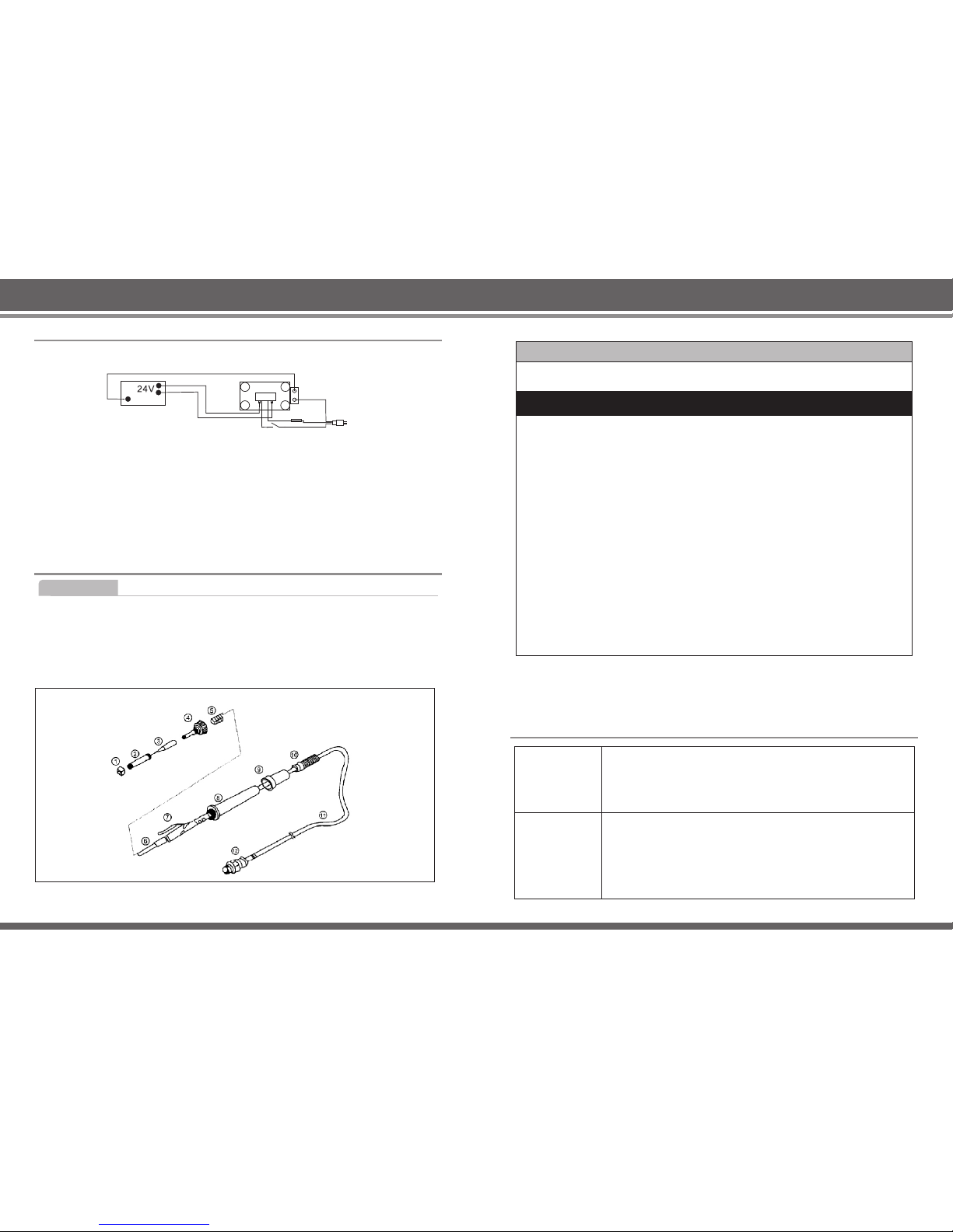
三、电路图
接地
印刷电路板
隔离变压器
3芯电线
四、烙铁发热芯和烙铁头的更换
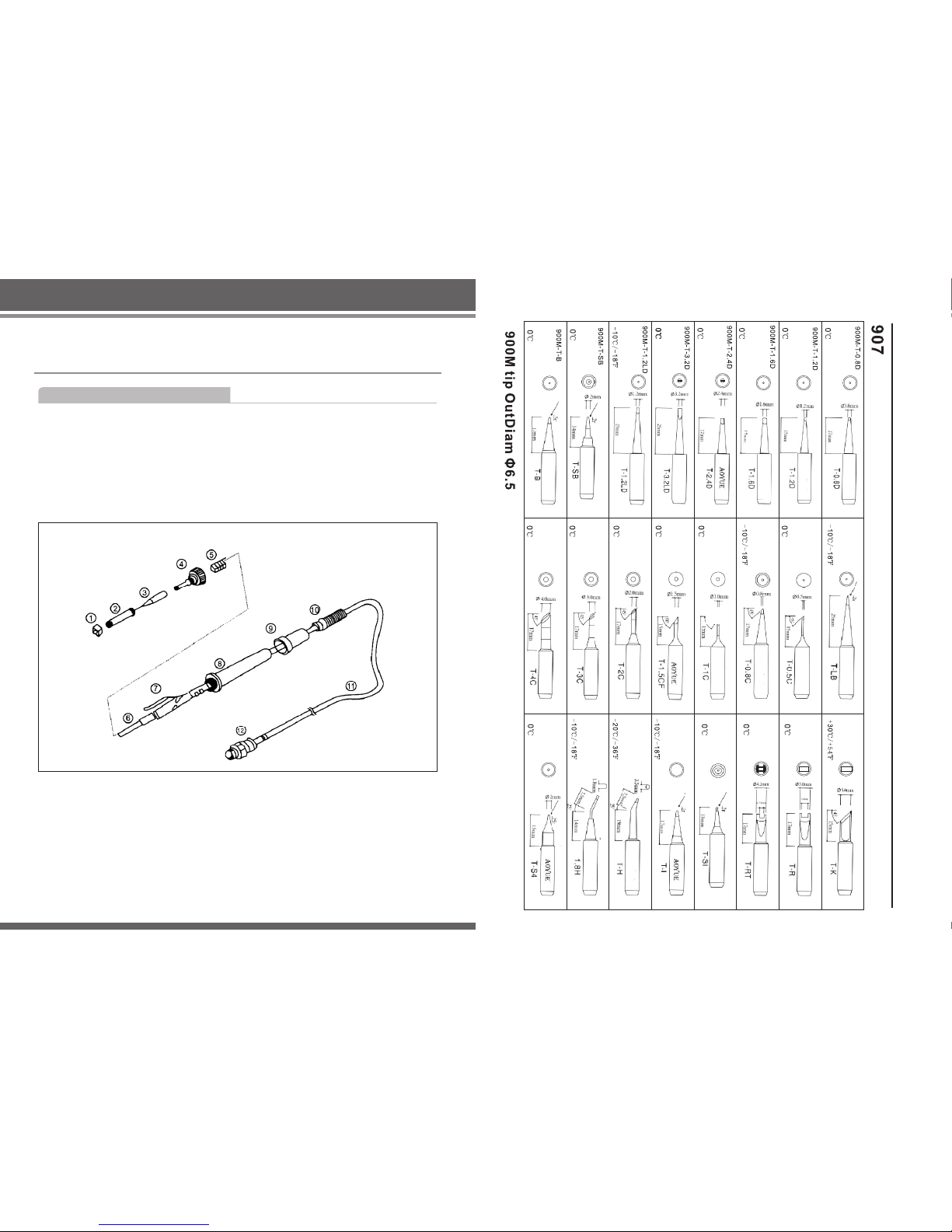
1、旋出螺母1,再将钢管2取出,这时就可以取下烙铁 头进 行更 换了 。
2、如需更换烙铁发热芯可继续旋出螺纹头4,拔出 烙铁 发热 芯6和线 路板7, 要注 意弹
簧5的连接线。
3、将烙铁发热芯从线路板上焊下,更换新 的发 热芯 ,装 好即 可。 注意 烙铁 发热 芯引 线
的连接顺序。
烙铁部件更换
图1
接地弹 簧
螺纹头
烙铁头
钢管
螺母
发热芯
线路板
手柄壳
硅胶套
线尾
航空座
手柄线
图1
Warning!!!
Use the mach in e, t he f ol lo wi ng b as ic m ea su re s sh ou ld abide, avoid ele ct ri c
shock or cau se i nj ur y or d am ag e ca us ed b y fir es .
1. To ens ur e pe rs onal safety, af te r th e machine complet ed w or k, p le as e tu rn
off t he m ai n po wer switch, and unp lu g th e po we r co rd i f lo ng t im e no u se .
2. You must use the o ri gi na l ap pr ov al o r re co mm en da ti on o f the parts, other wise it will l ea d to s er io us c on se qu en ce s.
3. Machine fa il ur e mu st b e by p ro fe ss io na ls o r th e co mp any designated pe r sonnel for r ep ai r.
4. Thi s pr od uc t is grounded three - w ir e pl ug , mu st b e in se rt ed w it hi n th e
three - hole g ro un de d ou tl et , do n ot c ha ng e th e pl ug s or u se u ngrounded
three adap te r ma de i t ba d gr ou nd ed .
5. Hot air gun or s ol de ri ng s ta ti on i s op en , it s te mp er at ure are likely to rea ch
400 . Do not use it ne ar fl am ma bl e ga s, o bj ec ts . Tub e an d th e he at e mi-°C
tted very ho t, c an b ur n th e bo dy, do not to uc h th e ho t pi pe a nd d ir ec t in je c tion to heat t he h um an b od y.
6. Before hot a ir g un t ur ne d on , pl ea se e ns ur e it i s in s af et y en vironment, do
not leave th e jo bs s it e.
7. When the hot a ir g un o pe ni ng d o no t in st al l no zz le , th e he at pipe and the
nozzle mus t be c oo li ng . Then ins ta ll ed t he o th er n oz zl e.
8. After use, th e ma ch in e ne ed t o co ol d ow n wh en p ac ki ng .
9. Do not use a sol de ri ng i ro n to w el d ou ts id e th e wo rk ; Do n ot i ron percussi on table to cl ea r th e re si du al fl ux , th is c ou ld s er io us ly d amage the iron.
10. The ma ch in e welding will ta ke s mo ke , pl ea se d o pr op er v en ti la ti on .
I. Ti p Maint enanc e And Use
Tip t em pe ra tu re
High sol de ri ng tem pe ra tu re can d eg ra de the tip . Use the
lo wes t po ssi ble sol der i ng tem p er a tu r e. The ex c ell ent
thermal re co ve ry c ha ra ct er is ti cs e ns ur e ef fic ie nt a nd e ff ec tive s ol dering ev en at lo w tempera tu re s. T hi s a ls o p ro te ct s
the solder d e it em s fr om t he rm al d am ag e.
Cleaning
Clean the ti p re gu la rl y wi th a c le an in g sp on ge . As ox id es and
carbides fr om the so ld er a nd flu x ca n f or m im pu ri ti es on the
tip. Th es e impu ri ti es can re su lt in defective jo in ts o r re du ce
the ti ps h ea t co nd uc ti vity. Whe n using t he s ol de ri ng iron
continuo us ly, b e su re to l oo sen t he tip an d remove al l oxides
at le as t on ce a we ek . Thi s he lp s pr ev en t se iz ure an d
reductio n of t he t ip t em pe ra tu re .
Page 4
When not in us e
Never le av e th e solderi ng i ro n si tt ing a t hi gh t em perature
foe long per io ds of tim e, as the tip ’s sol de r plating wil l
become cov er ed w it h ox id e, w hi ch c an g re at ly r ed uc e the
tip’s h ea t co nductivity.
After use
Wipe the tip c le an a nd c oa t th e ti p wi th f re sh s ol de r.
1. When sold er in g ir on i s us ed f or t he fi rs t ti me , yo u sh ou ld p ay attention to mon itor iron ti p wa rm in g si tu at io n, w ai t un ti l th e te mp er ature just melted t in w ir e, a
layer of tin o n th e pa rt o f th e go ld -p la te d ir on t ip ,a nd t he n the temperature w as
raised to th e re qu ir ed t em pe ra tu re . Ke ep i n mi nd w he n working iron tip sh ou ld
be long-te rm w it h a la ye r of t in t o pr ot ec ti on i ro n ti p, in o rder to achieve opt im al
solderin g fu nc ti on .
2. As an oxide la ye r on t he s ur fa ce o f ir on t ip , re su lt in g in f alse low temperat ur e
solderin g ir on t ip , un ab le t o me lt t in a nd t he t in , in f ac t, a t this time the heati ng
elements w it h th e so ld er in g ir on i s hi gh t em pe ra tu re state. Th is h ap pe ns situ ation not to b li nd t he t em pe ra tu re r is es a ga in , th e ap pl ication of clea n sp on ge
clear oxid es , su ch a s no t cl ea r, pl ea se t ur n of f th e po we r, so ld er in g ir on b e dr opped to roo m te mp er at ur e, w it h No .0 s an dp ap er a cc id entally cleared t he
oxide, the n re pe at t he o pe ra ti on o f th e fir st p oi nt i ro n in itial use.
3. Please pa y mo re a tt en ti on s ol de ri ng i ro n in h ig h te mperature work ba ck i nt o
iron holde r, sh ou ld b e ad ju st t em pe ra tu re b ut to n be low 250°C stand - by us e,
stand-by t im e ov er 2 0 mi nu te s, p le as e tu rn o ff p ow er. O th er wi se t he s ol de ri ng
iron in a high t em pe ra tu re f or l on g ti me . Be ca us e be tw ee n iron holder and
solderin g ir on g en er at e ac cu mu la te d te mp er at ure, lead to heatin g el em en ts
accelera te d ag in g, s ol de ri ng i ro n ti p de ri va ti ve oxide, directl y we ak en ed s ol d ering, sev er e wi ll r es ul t in t he c on ne ct in g sc re w nu t pl astic melt of the han dl e
or heating e le me nt s sh or t ci rc ui t.
4. If the tip de fo rm at io n or t he o cc ur re nc e of h ea vy e ro si on, to replace the ne w
one. (Note : Do n ot u se k ni fe fi le r em ov e ox id es o f so ld er in g iron tip.)
5. Solderi ng , do n ot g iv e ir on t ip s to o mu ch p re ss ur e, t hi s will not change the
thermal co nd uc ti vi ty, otherwi se w il l le ad t o ir on t ip d am ag e.
5 6
II. Sp ecific ati on
936/937D /9 36 B
45W 75W
24V AC
392°F~89 6° F392°F~89 6° F
200°C~48 0° C200°C~48 0° C
1.58kg (Co mm on h ea te r) 2.08kg (Im po rt ed h ea te r)
0~40°C/3 2° F~ 10 4° F
-20°C~80 °C /- 4° F~ 17 6° F
35%~45%
AC 24V ±10% 5 0H z
LED
±2°C (Stati c)
<2ohm
<2mV
Product mo de l
power
Output vol ta ge
Temperatur e ra ng e
Display ty pe
Temperatur e st ab il it y
Heating element voltage
Tip o f gr ou nd r es is ta nc e
Tip o f gr ou nd v ol ta ge
Wei gh t
Wor ki ng t em perature
Storage te mp er at ur e
Storage hu mi di ty
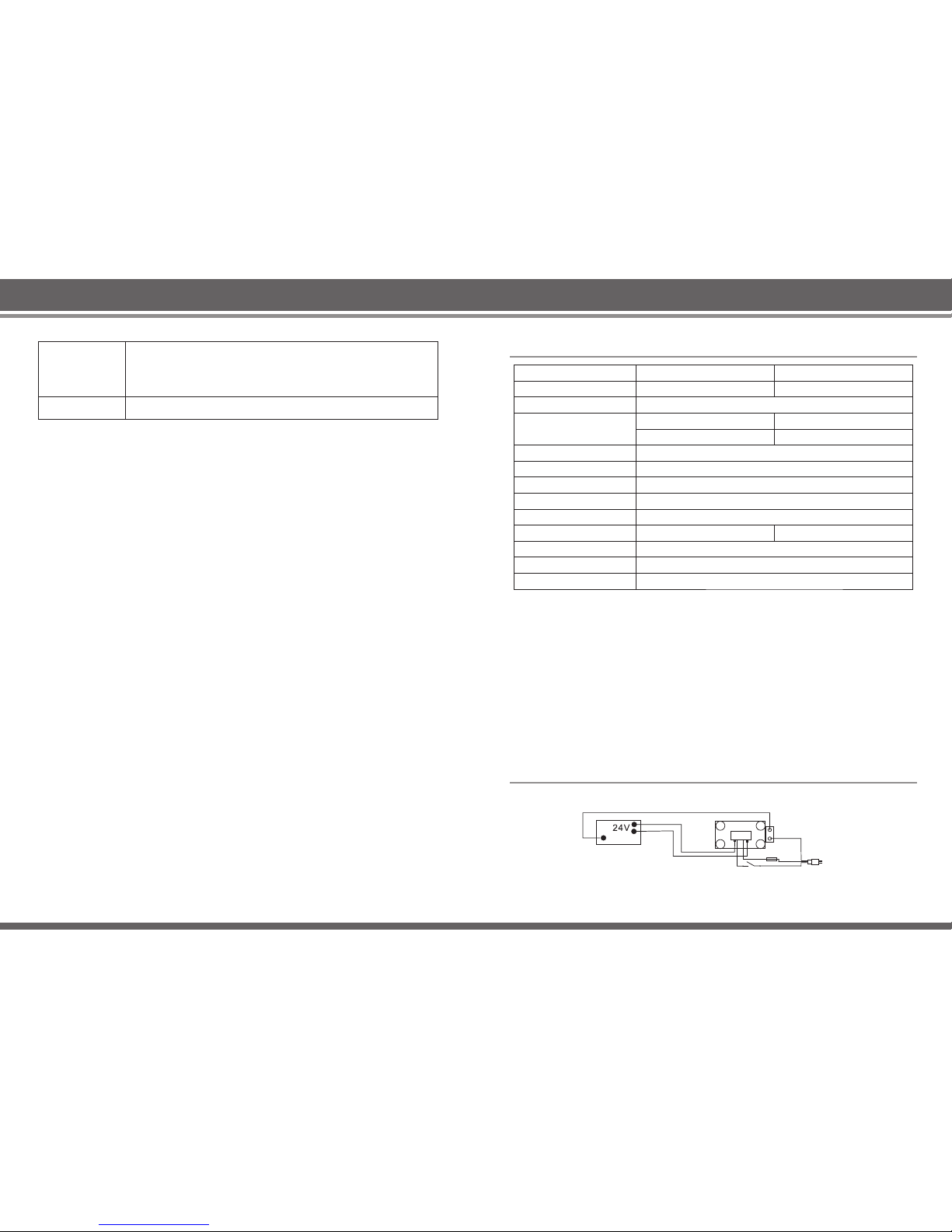
III. Wirin g Diagr am
P.W.B.
Ground
Tra ns fo rm er
3 Core
936A /937D+/939/939D/92 8/928D
Page 5
7
Solderin g ir on p ar ts r ep la ce me nt
IV. Rep lacement o f the sol derin g iron’s t ip an d
sold ering i ro n heating co re ’s ele ment
1. Unscrew s th e nu t No .1 , an d th en r em ov es t he s te el t ub e No .2 , followed by
removing t he t ip w hi ch i s go in g to b e re pl ac ed .
2. For the rep la ce me nt o f he at in g co re ’s e le me nt c an b e pe rf or me d by u ns cr ew ing the plas ti c ca p No .4 , pu ll s ou t ge nt ly t he h ea ti ng c or e, element No.6 a lo ng
with the cir cu it b oa rd N o. 7, p le as e ca re fu ll y re me mb er the connecti on o f sp ri ng No.5.
3. Th e ir on c or e from the circuit bo ar d we ld in g , th e re pl ac em en t of t he h ea ti ng
core, can be fi tt ed w el l. N ot e th at t he o rd er o f th e ir on c or e wi re connection.
Figure 1
Figure 1
Ear thing s pring
Thr ead hea d
Tip s
Ste el tube
Scr ew
Spo ol
Glo velik e
Han dle cov er
Boa rd
Hea ter
Han dle lin e
Voya ge seat
附:电焊台使用烙铁头型号图
Attachment: Electric welding machine usi ng weld ing head model figure
Page 6
产品合格证
Prod uc t certi fic ation
维修记录
Main te nance r ec ords
感谢您购买 本产 品, 在使 用本 产品 前请 您认 真阅 读以下条款:
Thank y ou f or c ho os in g th is t yp e of p ro ducts, plea se r ea d th e fo ll ow in g te rm s
befor e us in g:
1. 消费者由 购买 日起7天 内, 在正 常操 作情 况下 (非 人为 损坏),全新拆包,未经拆修 ,
可享受包换服务 。
From pu rc ha si ng d at e wi th in 7 d ay s, u nd er normal use (A rt ifi ci al d am ag e) ,n ew
packa ge , no t be d is as se mb le a nd r ep ai re d ,enjoy re pl ac em en t se rv ic e.
2. 消费者由 购买 日起 1 年 内, 在正 常操 作情 况下 ,出 现品质故障,未经拆修可享受 保
修服务。
From pu rc ha si ng d at e wi th in o ne y ea r, un de r normal us e, i f th er e ar e qu al it y
probl em , no t be d is as se mb le a nd r ep ai re d ,enjoy fr ee r ep ai r se rv ic e.
3. 在超过保 修期 终生 提供 保修 服务 ,免 收人 工费,只收取零件费。
For mor e th an w ar ra nt y, we p rovide a life ti me w ar ra nt y se rv ic e, f re e of l abor
costs , ch ar ge o nl y sp ar e pa rt s co st s.
4. 保修期内 若未 能出 示保 修卡 ,本 公司 不予 免费服务。
Failu re t o pr es en t wa rr an ty c ar d du ri ng warranty p er io d, t he c om pa ny w il l no t be
a free se rv ic e.
5. 用户需保 修商 品, 请先 与原 销售 单位 联系 。
Users n ee d wa rr an ty s er vi ce , pl ea se c ontact your o ri gi na l sa le s un it .
6. 用户保修 时需 提供 保修 卡和 购买 发票 或有 本公司印章的收据凭证。
When us er s ne ed w ar ra nt y se rv ic e, p le ase provide w ar ra nt y ca rd a nd p ur ch as e
invoi ce , or r ec ei pt o f th e ce rt ifi ca te o f the company s ea l.
7. 保修不包 括运 输费 用和 不提 供上 门服 务。
War ra nt y does not incl ud e tr an sp or ta ti on c os ts a nd p rovide on-s it e se rv ic e.
产品保修卡
War ran ty C ard
出厂日 期(Date o f manuf actur e)
售货日 期(Sale s Date)
产品型 号名称(Mo del NO. )
产品编 号(Prod uct ID)
检验(E xamin e )
QC
PASS
经检验 产品符合技 术标准
Upo n exami natio n produ cts mee t techn ical st andar ds
序号
NO.
送修日 期
Dat e for rep air
故障原 因
Cau se
修好日 期
Fix d ate
维修员
Rep airer
 Loading...