

Page 1
BeoLab 4000 MKII
Type 6642, 6643, 6644, 6645, 6646, 6647, 6648
Service Manual
English
German, French, Italian, Spanish, Danish, Dutch and Japanese versions
are available in the Retail System
This Service Manual must be returned
with the defective parts/back-up suitcase !
Page 2

CONTENTS
Survey of modules .................................................................... 1.1
How to service .......................................................................... 1.2
Warnings – Insulation test ......................................................... 2.1
Adjustments ............................................................................. 3.1
Repaie tips ................................................................................ 4.1
Replacement of modules ........................................................... 5.1
Specification guidelines for service use ...................................... 6.1
Block diagram ........................................................................... 7.1
Wiring diagram ......................................................................... 7.1
Available parts .......................................................................... 8.1
Page 3
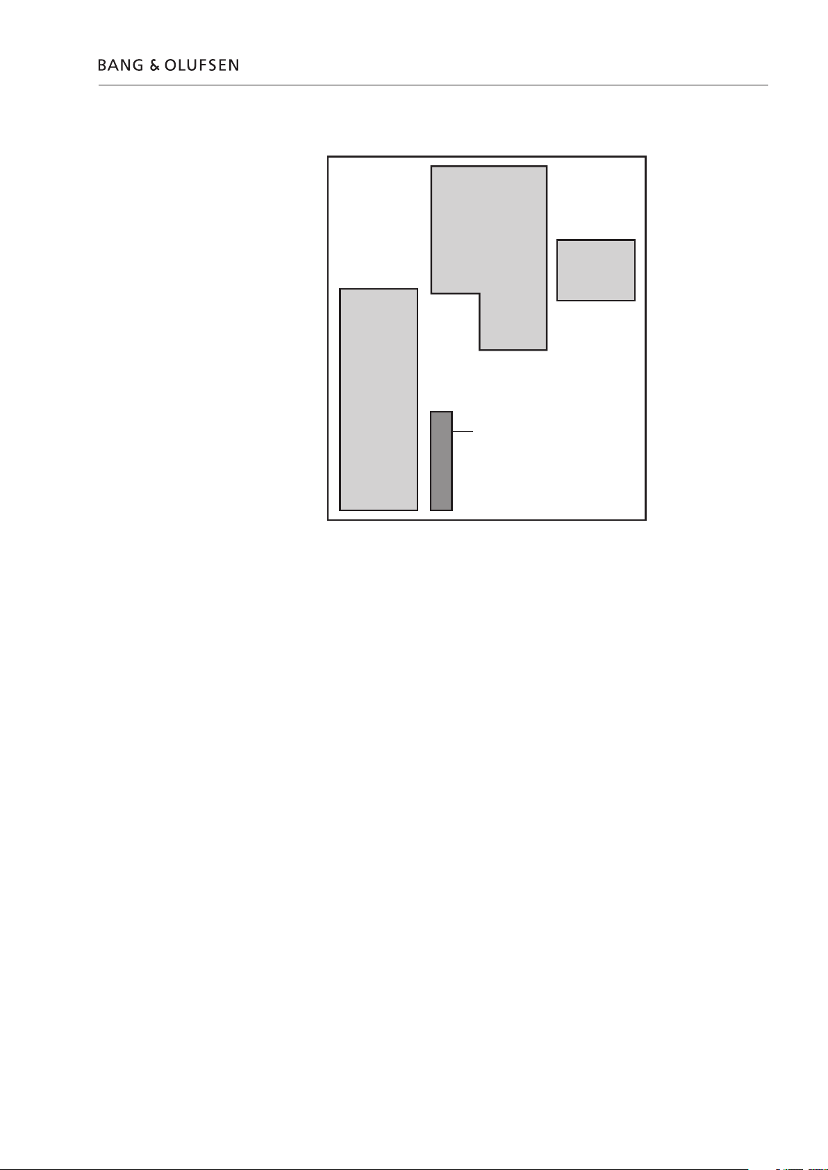
Survey of modules
1
2
3
4
Survey of modules 1.1
PCB01 Amplifier
PCB02 SMPS
PCB03 Main PCB
PCB04 LED
Page 4

1.2 How to service
How to service
Front line service
BeoLab 4000 MKII is to be serviced in the customer’s home when it comes to
electrical symptoms or exchange of mechanical parts. In this way you avoid having
to make more than one visit and using minimum of time on the case, all for the
benefit of the customer.
BeoLab 4000 MKII has been split-up into as few service items as possible. Each
service friendly item is packed individually, prepared for worldwide transport, and
has a separate seven digit spare part number to be found in the Service Manual or
on the Bang & Olufsen Retail System. The exploded view drawing will show the
service spare parts.
All necessary electrical modules and the two loudspeaker units can be ordered to
prepare front-line service. Cabinet parts must also be brought with you separately,
if to be replaced in the customer’s home.
To improve the quality and secure a better service please send the defective part
for quality analyse purposes to:
Att:
Bang & Olufsen Operation a/s
Att.: JEB 7210-3
Peter Bangsvej 15
DK-7600 Struer
Delivery
Installation and setting-up
Fault Finding
Please remember to fill-in a fault description (part no.: 3542206).
There is several type numbers for BeoLab 4000 MKII, however, this is only due to
market approvals. All types can be used on all markets with 100 to 240 V (ac)
mains voltage. When you order BeoLab 4000 MKII (set of two) two mains cables
and two Power Link cables are included.
Only the switch for Left, Right or Line must be set into correct position as
described in the User Guide, before Power Link or a Line signal and AC power
wires are connected. If Power Link is used, the switch is for Left or Right setting. If
a Line signal (0 to 1V) is connected (via phono-male to PL Line-in) part no. see
Parts not shown) the switch must be set to Line position. See more details in the
User Guide. The LED will indicate on (green) or off (red).
Before troubleshooting is initiated, let the customer demonstrate the fault, if
possible. There are four electrical modules in the product. Therefore a faulty
module is easy to point out in most cases. The PCB’s has been divided into:
PCB01, Amplifier - PCB02, SMPS - PCB03, Main PCB and PCB04, LED.
No special service programs are available in this product or via the ServiceTool.
If there is a fault in the PCB02, SMPS or PCB01, Amplifier the LED is typically off.
Replacement
Each loudspeaker is individually adjusted from production to ensure optimal stereo
perspective. When replacing a speaker unit bass/treble level have to be adjusted.
On the back of the new unit will be printed a rated value for the sensitivity of the
particular unit. The rated value is rated in dB.
Page 5

Warnings
ESD
ESD-Mat
ESD
Handling
Cleaning
Warnings – Insulation test 2.1
When electrical replacement or disassembly is taking place, use an ESD-mat. The
internal electronics are very sensitive to static electricity.
Wear cotton gloves to avoid any fingerprints on the product.
The surfaces on the product are very sensitive, so handling should be done with
great care to avoid damage.
Clean the surfaces of the BeoLab 4000 MKII using a soft, lintfree cloth which you
have wrung firmly in a solution of lukewarm water containing a few drops of mild
household cleaner, for example a dish washing detergent. The cooling fins on the
rear may be cleaned using a soft brush or a vacuum cleaner. The front cloth may
be cleaned with a vacuum cleaner set to the lowest level.
Insulation test
Note: Never use alcohol or other solvents to clean any part of the BeoLab 4000 MKII !
The product must be insulation tested after having been dismantled. Make the test
when the set has been reassembled and is ready to be returned to the customer.
Flashover must not occur during the test.
Make the insulation test as follows:
Short-circuit the two pins of the mains plug and connect them to one of the
terminals of the insulation tester.
Connect the other terminal to ground on the Power Link socket.
NOTE!
To avoid damaging the product it is essential that both terminals of the insulation
tester have good contact.
During the test the current must not exceed 10 mA.
Slowly increase the voltage on the insulation tester until a voltage of 2.5 kV (ac) is
obtained. Maintain the voltage level for one second, then slowly decrease the
voltage to 0 V (ac).
Page 6
LI NE
L
R
1 2
POW ER
LIN K
W T
12
3
1
2
11
10
9
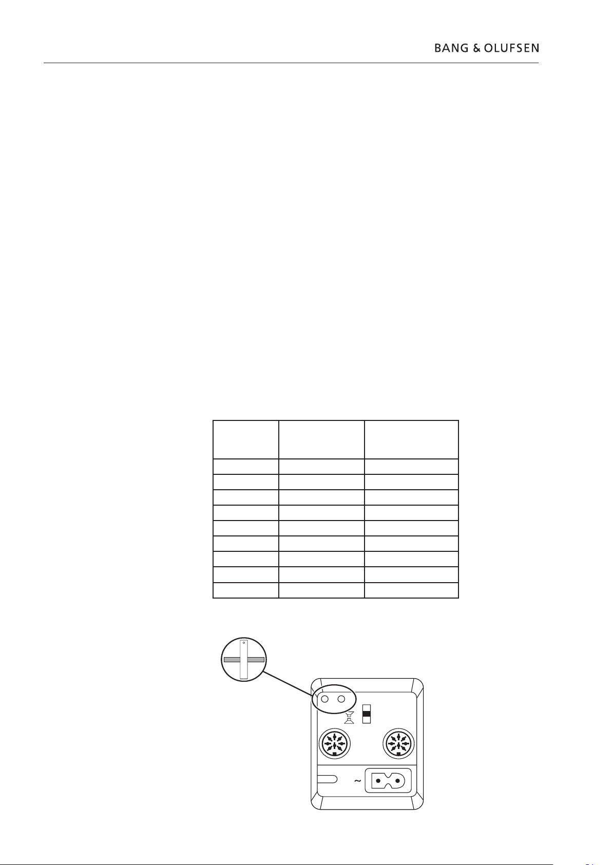
3.1 Adjustments
Adjustments
Adjustments after replacing PCB03, Main PCB
Adjustments of bass/treble levels
After replacing a speaker unit
- Adjust treble level by means of (R301) and the bass level by means of (R312).
- Adjusts according to the drawing and table 1. Only the potentiometer of the
Read out the adjustment position of the old potentiometers, R301 & R312, and
set the new potentiometers to the same position.
Each loudspeaker is individually adjusted from production to ensure optimal stereo
perspective. When replacing a speaker unit or PCB03, Main PCB, bass/treble levels
have to be adjusted. On the back of the new speaker unit will be printed a rated
value for the sensitivity of the particular unit. The rated value is stated in dB and
have to be converted to a mechanical position of the two potentiometers by using
table 1 and fig.1.
These two potentiometer are accessible via the two holes in the socket well, see
fig. 1.
replaced unit have to be adjusted.
Table 1
Fig.1
WARNING: Do under no circumstances adjust the level of a unit that has not been
replaced!
‘‘Clock position’’
(The new position
of the
potentiometer)
Bass deviation ±dB Treble deviation ±dB
0830 +3.1 +3.9
0900 +2.7 +3.3
1000 +1.8 +2.2
1100 +0.9 +1.1
1200 0.0 0.0
0100 -0.9 -1.1
0200 -1.8 -2.2
0300 -2.7 -3.3
0330 -3.1 -3.9
Page 7
Repair tips
Power Link
MK III
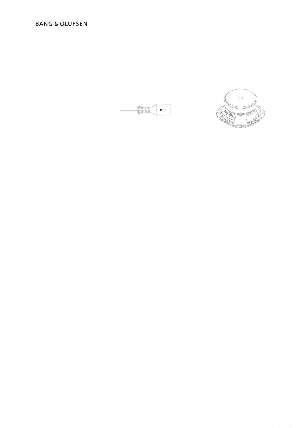
Hum in loudspeaker when no music is played
Check loudspeaker units
Repair tips 4.1
The Power Link cable must be of type MK III or higher.
The ground connection in Power Link cable lower than MK III may be insufficient
for optimum sound performance.
The loudspeaker units can be checked by an ohm-meter.
OK values for tweeter and woofer are approx. 6 W.
How to check the Switch Mode Power Supply
- Take off the baffle.
- Connect an audio signal (set the input switch corresponding to the applied signal).
- Connect mains, 100 - 240V.
- Confirm 12V standby on PCB02, SMPS P2 pin 6, GND pin 3 (if not OK, replace
PCB02, SMPS).
- Confirm 12V HT_ON, on PCB02, SMPS P2 pin 8 (if not OK replace PCB03, Main
PCB).
- Confirm ±12V on PCB02, SMPS P2 +12V pin 1, 2 and -12V pin 4, 5 (GND pin 3).
If not OK replace PCB02, SMPS.
Page 8

4.2
Page 9

Replacement of modules
ESD
ESD-Mat
Modules that can be replaced
Warning – Static electricity
5.1Replacement of modules
BeoLab 4000 MKII in service position ......................... 5.2
Replace PCB01, Amplifier .......................................... 5.4
Replace PCB02, SMPS ................................................ 5.5
Replace PCB03, Main PCB ......................................... 5.6
Replace PCB04, LED ................................................... 5.7
Static electricity may damage the product.
A static-protective field service kit must always be used when the product is
disassembled or modules are being handled.
Notice!
All modules must be placed on the ESD-mat or in an ESD-proof bag.
Purpose of replacement of modules
- The correct sequence for replacing modules.
- Text and illustrations.
- Reference to adjustment.
Adjustments
Short instructions for replacement of the available modules, with reference to
additional illustrations:
After replacing PCB03, Main or a loudspeaker an adjustment is required, see
adjustments.
Page 10

BeoLab 4000 MKII in service position
LINE
L
R
1 2
POWER
LINK
5.2
- Remove cables connected to BeoLab 4000 MKII
- Remove front frame
- Remove profile
- Remove screws for baffle
2x
TX10
10x
TX10
Page 11

- Remove cables for speaker units
BeoLab 4000 MKII in service position
5.3
Page 12

5.4 Replace PCB01, Amplifier
+ 5.2 BeoLab 4000 MKII in service position
- Remove screws
- Remove cables on backside of PCB
4x
TX10
4P300
4P301
Page 13

5.5Replace PCB02, SMPS
+ 5.2 BeoLab 4000 MKII in service position
- Remove cables
- Remove screws and pull out PCB02, SMPS
2P1
2P2
6x
TX10
Page 14

5.6 Replace PCB03, Main PCB
+ 5.2 BeoLab 4000 MKII in service position
- Remove screws and pull out PCB03, Main PCB
- Remove ground cable!
- Remove cables
5x
TX10
Ground
3P300
3P103
3P100
Page 15

+ 5.2 BeoLab 4000 MKII in service position
- Remove screw and pull out LED
- Remove screws and pull PCB04, LED out
5.7Replace PCB04, LED
1x
TX10
2x
TX10
- Remove screw and pull off light guide
1x
TX10
Page 16

5.8
Page 17

Specification guidelines for service use
Specification guidelines for service use BeoLab 4000 MKII
Type 6642 (EU), 6643 (GB), 6644 (US), 6645 (J), 6646 (AUS), 6647 (KOR)
6648 (CN)
Power supply:
Voltage 100-240 Volt
Power consumption Typical: 6 W, Standby: 0.5 W
Cabinet finish Grey, black, dark grey, yellow, red/black, blue/black
Front cloth Grey, black, dark grey, yellow, red, blue
Dimensions W x H x D 28 x 32 x 16 cm (with wall bracket)
Weight 4.5 kg
Indicator LED for On (green) or Off (red)
Operation Left, Right or LINE, switch
Protection Thermal protection of SMPS
Tweeter protection
System data:
Effective Frequency range 55–20,000 Hz
Sound Pressure Level (SPL) 97 dB/IEC noise 3 m/stereo/room
Input impedance 47kW
Harmonic distortion <6% 90 dB SPL/1 m/250-1000 Hz
<2% 90 dB SPL/1 m/1000-5000 Hz
Electronics:
Active crossover network Linkwitz/Riley
High pass filter 30 dB/octave, 51 Hz
Low frequency equalization 51 Hz/+10 dB
Bass equalization ABL (Adaptive Bass Linearization)
6.1
Acoustics and cabinet:
Cabinet principle Bass reflex
Woofer 114 mm (4½”), 8W
Tweeter 18 mm (¾”), 8W
Magnetically shielded Yes
Crossover frequency 3.3 kHz
Net volume, bass 4 litres
Power amplifier:
Signal to noise ratio >= 84 dBA (1W in Woofer)
Input sensitivity/impedance:
Input sensitivity Power Link & Line 125 mV (88 dB SPL) Auto switch on
Power link sockets 1V/47 kW
Power link channel separation >55 dB/10,000 Hz
Standby function Automatic On-Standby
Switch off time (line) 3 min.
Power amplifier, bass 30 W, Class D, ICE power®
Power amplifier, treble 30 W, Class D, ICE power®
Long-term maximum output power 56 W
Connections:
Power Link 2 x 8-pin socket
Pin 1 Power up/down not used
(interconnected between the two Power Link plugs )
Pin 2 Signal GND
Pin 3 Left in (also used for line in. Note: pin2&7 in the plug
must be connected when used for line in)
Pin 4 Loudspeaker on/sense => 2.5V, OFF =< 0.5V
Pin 5 Right in
Pin 6 Data (Not used)
(interconnected between the two Power Link plugs )
Pin 7 Data GND
Pin 8 (Not used)
(Jacket: No connect)
Subject to change without notice
Page 18

6.2
Page 19

P301
4/5pinsPlug
>
>
>
>
P300
Plug
>
>
>
>
<
>
>
8/8pins
AMPLIFIER
01
Plug
P300
>
>
<
>
>
>
>
8/8pins
W03
P103
Plug
>
>
3/3pins
Plug
P104
>
>
3/3pins
W04
04
LED
MAIN PCB
03
SMPS
02
P100
Plug
>
>
>
>
>
<
8/8pins
P2
Plug
>
>
>
>
>
<
8/8pins
W02
2/3pinsP1Plug
>
>
W01
W05
Tweeter level Woofer level
Power Link 1
Power Link 2
Line R/L
AC Inlet
Neutral
Live
Tweeter
Black
Red
Woofer
White
Purple
G
R
GND
R302
R312
PCB04, LED
PCB03, Main
PCB02,
SMPS
PCB01,
Amplifier
Autostart
HT On
1
2
Tweeter gain adjust
EQ
notch
4 kHz
EQ
notch
7 kHz
H. P. F
fc
3200 Hz
Tweeter
Protection
Limiter
H. P. F
fc
3200 Hz
Differential
Output
Tweeter
Tweeter
amp.
gain
20dB
ICE power
Woofer
amp.
gain
20dB
Woofer
MUTUAL EQ
750Hz
notch
1.35kHz
notch
2.4kHz
peak
ABL
L. P. F
fc
3560Hz
Filter PWB
L. P. F
fc
3560Hz
Differential
Output
Gain 12dB
Woofer
Gain adjust
1
2
Input amp.
DIN input
Input
select
AC in
+12V stby.
+/-12V
HT on
Block diagram
7.1Block diagram – Wiring diagram 7.1 7.1 Block diagram – Wiring diagram
Wiring diagram
Page 20

Baffle
Baffle – left
Baffle – right
!
!
9001
9002
9104
9101
9102
9102
9103
9001
9005
9004
9003
9003
9014
9006
9007
9008
9009
9013
9012
9010
9011
9015
9016
9017
9018
9019
9020
9020
9021
1
3
2
4
1
1
1
1
2
3
3
1
1
1
1
2
4
4
4
4
4
4
5
8
8
7
6
6
6
6
6
6
6
6
6
6
6
6
6
4
4
4
4
4
4
9
9
9
9
2
10
10
10
11
11
12
10
10
10
10
11
10
10
10
10
10
10
10
10
10
Incl. pos. nos.
9004, 9005
Incl. pos. nos. 9004, 9005
Available parts
Available parts 8.1 8.1 Available parts8.1
Page 21

Available parts 8.2
BeoLab 4000 MKII
9001 3451181 Top/bottom, red
3451227 Top/bottom, blue
3451242 Top/bottom, dark grey
3456201 Top/bottom, aluminium
3456202 Top/bottom, black
3456205 Top/bottom, yellow
9002 3358346 Heat sink incl. pos. nos. 9004, 9005
9003 3947350 Foam tape, 10m
9004 3340136 Gasket
9005 3340090 Gasket
9006 3169054 Bracket incl. pos. nos. 9004, 9005
9007 3170226 Shield
9008 3152399 Holder f/PCB2
9009 3151432 Holder f/PCB1
9010 2576128 Adapter
9011 6150039 Light guide
9012 3340134 Gasket f/light guide
9013 2938320 Bush f/light guide
9014 3440162 Baffle, left
9015 3440163 Baffle, right
9016 8480321 Tweeter
9017 8480384 Woofer
9018 3320300 Front frame, black
3320742 Front frame, grey
3320750 Front frame, yellow
3320885 Front frame, dark grey
9019 2568090 Set of profiles, black
2568111 Set of profiles, yellow
2568148 Set of profiles, red
2568150 Set of profiles, blue
2568158 Set of profiles, dark grey
9020 2816315 Spring
9021 3332015 Set of gaskets
Screws etc.
Wires
01Module 8003563 PCB01, Amplifier
02Module 8003556 PCB02, SMPS
03Module 8003562 PCB03, Main PCB
04Module 8003555 PCB04, LED
9101 3031601 Bracket f/wall
9102 3031620 Bracket f/speaker
9103 2816297 Clips
9104 3031651 Wall bracket, complete
1 2013177 Screw 3 x 13mm
2 2816298 Spring
3 2042053 Screw 4 x 16mm
4 2013229 Screw 3 x 6mm
5 7530087 Solder tab
6 2013137 Screw 3 x 10mm
7 7530119 Solder tab
8 2015182 Screw 3 x 13mm
9 2015132 Screw 3.5 x 10mm
10 2015139 Screw 3.5 x 16mm
11 2054046 Screw 3.5 x 12mm
12 3340137 Gasket
The W number refers to the Wiring diagram page 7.1
W01 6278171 Wire, Inlet
W02 6278172 Wire, SMPS
W03 6278173 Wire, Amplifier
W04 6278174 Wire, LED
W05 6278175 Wire, speaker
Page 22

8.3 Available parts
Mains cables
Packing
Parts not shown
Accessories
Available documentation
6100273 Mains cable, EU, 3m
6100329 Mains cable, UK, 3m
6100307 Mains cable, US, 3m
6100331 Mains cable, JP, 3m
6100332 Mains cable, AUS, 3m
6100386 Mains cable, KOR, 3m
6100047 Mains cable, China, 3m
3397996 Set of foam
3392504 Outer carton
3658262 Product cover
3103325 Rubber foot
3040030 Allen key
6270041 Power Link cable MKIII, 5m, black
1203726 Base
6270856 Phono male to PL line-in, black, 5 m
6270433 Stereo mini-jack (male) to 2 x phono-female, black, 3m
See Retail Ordering System
Page 23

Incl. pos. no. 9210
9210
9211
9201
9202
9203
9204
9205
Available parts 8.4
Floor Speaker Stand – type 2069
9201 3031707 Fitting
9202 2072119 Fixing screw
9203 2950216 Aluminium tube
9204 3459257 Cover plate
9205 2752081 Foot incl. pos. no. 9210
9210 3103392 Foot “soft”
9211 3103390 Foot “spike”
3390616 Bag w/parts (2 screws 4x12mm, 6 pcs. of pos. no. 9211 and 1 torx key
3504637 Setting-up guide
3392710 Outer carton
3396136 Foam packing top/bottom
Page 24

8.5
Page 25

Page 26

Bang & Olufsen
DK-7600 Struer
Denmark
Phone +45 96 84 11 22*
Fax +45 97 85 39 11
3538061 03-07
 Loading...