

Page 1

BeoLab 3
Type 6881, 6882, 6883, 6884, 6885, 6886, 6887, 6888
from serial no. 19355490
Service Center repair guide
English
Page 2

CONTENTS
How to service, Warnings, PIN code protection .......................................... 1
English ................................................................................................ 1.1
German .............................................................................................. 1.3
French ................................................................................................ 1.5
Italian ................................................................................................. 1.7
Spanish ............................................................................................... 1.9
Danish .............................................................................................. 1.11
Nederlands ....................................................................................... 1.13
Japanese ........................................................................................... 1.15
Specication guidelines for service use ....................................................... 2
Diagrams ........................................................................................................ 3
Overall block diagram ......................................................................... 3.1
Wiring diagram ................................................................................... 3.2
Available parts ............................................................................................... 4
Service tips, Replacements, Cleaning ........................................................... 5
English ................................................................................................ 5.1
German .............................................................................................. 5.3
French ................................................................................................ 5.5
Italian ................................................................................................. 5.7
Spanish ............................................................................................... 5.9
Danish .............................................................................................. 5.11
Nederlands ....................................................................................... 5.13
Japanese ........................................................................................... 5.15
Disassembly .................................................................................................... 6
Insulation test ................................................................................................ 7
English ................................................................................................ 7.1
German .............................................................................................. 7.2
French ................................................................................................ 7.3
Italian ................................................................................................. 7.4
Spanish ............................................................................................... 7.5
Danish ................................................................................................ 7.6
Nederlands ......................................................................................... 7.7
Japanese ............................................................................................. 7.8
There is no Brief operation guide in this Service Center repair guide.
Instead an english version of the user guide is enclosed the back-up suitcase.
Page 3

How to service
Front line service
BeoLab 3 must be serviced in the customers home when it comes to electrical
symptoms or exchange of mechanical parts. In this way you avoid having to make
more than one visit and using minimum of time on the case, all for the benet of
the customer.
The loudspeaker dimensions are H-215mm, W-135mm, L-162mm, 2,55 kg and
the carbon box for two loudspeakers are H-350mm, B-360mm, D-380mm, 6,5 kg.
In the customers house it is possible to replace :
The electrical parts :
The loudspeaker units
The passive radiators
The complete main chassis
The standby LED PCB
The mechanical parts :
The lens for the tweeter
The cabinet
The foot
A sound level adjustment procedure is necessary when replacing one or more
loudspeaker units, or replacing the main chassis. This is done easily be means of
click potentiometers.
Replacements of the cabinet can be done at the customers as it consist of a
complete cabinet with gaskets and other materials there are needed when
exchanging the complete cabinet. Only the lens, the loudspeaker units, the main
chassis and the foot must be put onto the new cabinet.
Back-up Suitcase
The service Back-up Suitcase will contain all needed electrical parts, that is needed
to service a failing speaker. All mechanical parts must be ordered separately from
B&O Struer DK. All the needed tools and a Service Center Repair Guide will be
found in the suitcase.
Converting mains voltage supply
If it is necessary to change voltage supply, e.g. when moving between two
countries, this can be done easily in the BeoLab 3 speakers (on module 01 – P504).
You will only need to mount/remove a jumper. The fuse will be a global type, so
here is no need for replacement. Remember to order new mains cables.
See illustration on page 6.11
Type survey
Variants Type Jumper P504 Mains cable
EU 6891 NOT mounted 6100273
GB 6892 NOT mounted 6200327
US/CDN 6893 Mounted 6100307
JAP 6894 Mounted 6100331
AUS 6895 NOT mounted 6100332
KOR 6896 NOT mounted 6100386
How to service, English 1.1
Page 4

1.2 Warnings – PIN code protection, English
STATIC ELECTRICITY
MAY DESTROY THE
PRODUCT
Warnings
ESD
When electrical replacements or disassembly is taking place use an ESD-mat. The
internal electronic are very sensitive to static electricity.
General warnings
Wear cotton gloves to avoid any ngerprints on the product.
The surfaces on the product is very sensitive, so handling should be done with
great care to avoid damage.
Cleaning of the speaker surfaces should only be done a lint-free cloth, which you
have dipped in lukewarm water and wrung rmly.
When doing disassembly small aluminum chips can occur when screws are
removed. Make sure all these small aluminum chips are removed from the speaker
cabinet before assembly is done. These aluminum chips can resolve in internal
shortcuts, and damage the Main chassis badly, if not removed.
If the speaker needs to be transported, a product cover can be ordered from B&O
(ordrenr. can be found in the back of this guide)
Page 5

Specication guidelines for service use BeoLab 3
Type no. 6891 Europe – 230V
Type no. 6892 England – 230V
Type no. 6893 USA, Canada – 120V
Type no. 6894 Japan – 100V
Type no. 6895 Australia – 240V
Type no. 6896 Korea – 220V
Dimensions for one speaker Height – 215mm (223mm on foot)
Width – 135mm
Length – 162mm
Weight – 2,55 Kg
Box for two loudspeakers Height – 350mm
Width – 360mm
Depth – 380mm
Weight – 6,5 Kg
Input sensitivity
Power Link 125mV – 88dB SPL
Line in (via Power Link socket, pin 3) 125mV – 88dB SPL (auto switch on)
Switch off time 3 min.
Maximum Sound Pressure Level 94 dB (Stereo, pair)
Power Ampliers 2 (Class D ICEpower)
Power amplier, bass 125 Watts, Class D, ICEpower
Power amplier, treble 125 Watts, Class D, ICEpower
Long Term Maximum, output per amplier Bass : 220 Watts (4 Ohm)
Treble : 120 Watts (8 Ohm)
Effective Frequency range 50 – 20.000 Hz
Crossover frequency 3300 Hz
Cabinet principle Double passive radiator system
Magnetically shielded Yes
Net volume, bass 1.5 litres
Woofer 4” (101,6 mm)
Passive radiators 2 x 4” (101,6 mm)
Treble ” (19mm)
Directivity control Treble *Acoustic Lens Technology
Bass equalization ABL (Adaptive Bass Linearization)
Protection Thermal protection
Connections
Power Link - input 1 (PL MKIII Semi-Balanced)
Mains – input 1
LINE in – input (via Power Link socket – pin3) 1 (auto switch on)
Indication 1 tri-color LED
Green On
Red Stand-by
Orange Protection (see “Service Hints”)
Operations
Switch for : Left – Right – LINE
Switch for : Wall – Corner – Free
Power consumption Typical : 7 Watts
IEC65 : 20 Watts
Stand-by : 0.2 Watts
*ALT (or Acoustic Lens Technology) is licensed from Sausalito Works LLC.
Specication guidelines for service use 2.1 2.1 2.1
Page 6
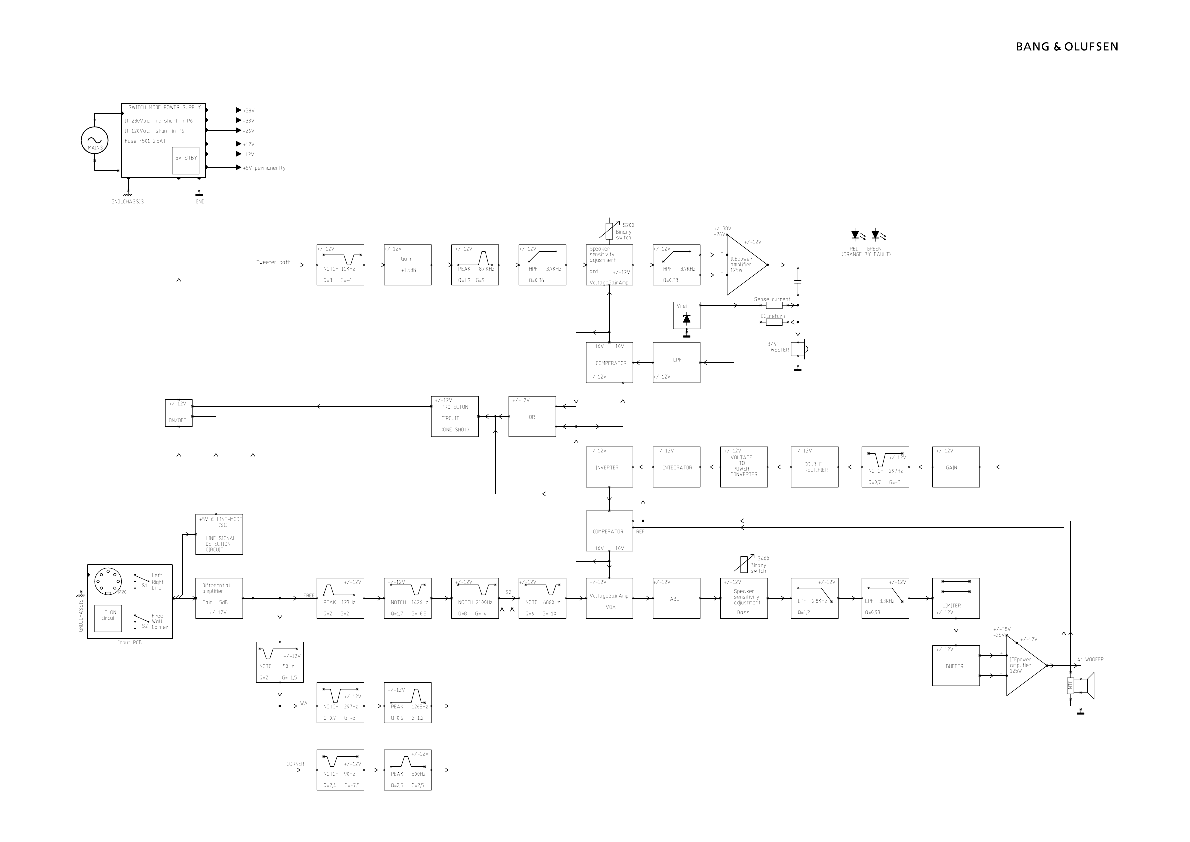
3.1 Overall block diagramOverall block diagram 3.13.1
Overall block diagram
Page 7

3.2 Wiring diagramWiring diagram 3.2 3.2
Wiring diagram
6
Page 8
4.1 Available partsAvailable parts 4.1
4.1
Available parts
BeoLab 3
9001
9002
9004
9005
9006
9007
9008
9009
9010
9011
9012*
9013
9014
9015
9015
Incl. pos. no. 9003
9003
Incl. pos. no. 9005
Incl. pos. no. 9007
9018
9018
9019
9020
9016
9017
9015
9026
9027
9028
9022
9024
9018
9019
9021
9025
9012*
5
999
6
1
1
1
1
1
1
2
2
2
2
2
3
3
3
3
3
3
3
3
3
3
3
3
4
5
6
7
8
9012*
Consist of pos. nos.
9009, 9011, 9013, 9014, 9015,
9022, 9023, 9024, 9025
9023
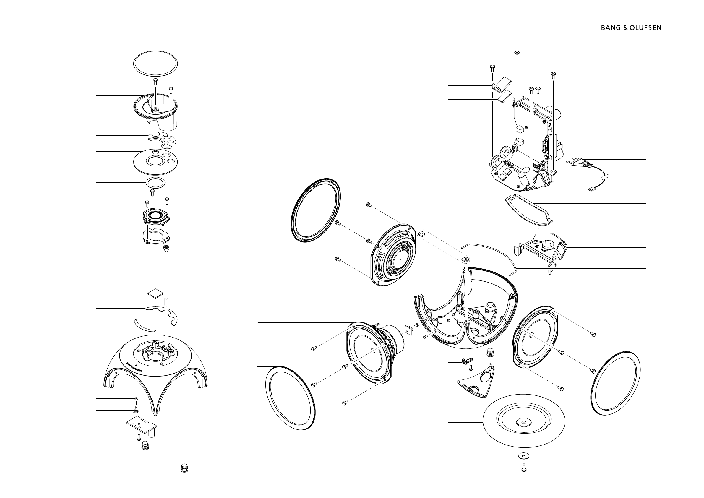
Page 9

Available parts 4.2
Top plate
Acoustic lens w/ lt
Tweeter cover w/gasket
Tweeter 19mm w/gasket
Thermal conductive rubber
Thermal conductive rubber
Woofer
Wire holder
8052223
Washer
Page 10

Wire bundles
Wire bundle, PCB2 - PCB5
Wire bundle, PCB3 - PCB5
Wire bundle, PCB3 - PCB6
3395305
Accessories
Available documentation
Page 11

Available parts 4.4
Tube
9501
Incl. pos. no. 9006
9502
9503
9504
9505
9506
Page 12

Table stand 2166
Tube
9512
9513
9511
9510
Page 13

Wall bracket 2167
9521
9520
9522
9520
Page 14

Page 15

Service hints and adjustment
Service Hints
Doing fault searching, the BeoLab 3`s LED can give you a hint.
If the LED turns orange in colour it can be a result of a thermal shutdown, remove
the mains and let the speaker cool down. If the LED still light orange when the
mains is connected again, then it is a indication of an internal error.
A internal error indication can be caused by many things, but the most likely is
listed below.
1. The NTC module on the bass driver unit is not connected to the Main chassis, the
plug is disconnected.
2. Tweeter unit is failing (How to measure the driver units is described later on this
page)
3. Bass unit is failing (How to measure the driver units is described later on this page)
4. Error in Switch Mode Power Supply
How to measure the Driver units (treble/bass), using a Ohm-meter :
Dismantle the speaker to get access to the driver unit you want to measure.
Disconnect the unit completely
Measure with an Ohm-meter
The bass unit should be 4,0 Ohm +/- 10% (between 3,6 - 4,4 Ohm)
The treble unit should be 6,4 Ohm +/- 10% (between 5,7 - 6,9 Ohm)
If the measurements are below the – 10% value, it indicates that the driver unit
coil is shortcut.
If the measurements is over the + 10% value, it indicates that the driver unit coil is
disconnected.
Adjustment after driver unit or Main chassis replacement
When a driver or a Main chassis is replaced, the driver unit levels needs to be
adjusted, so the speaker once again is in accordance with specications.
The adjustment is done with two click-potentiometers, one for treble level
adjustment and one for bass level adjustment. Each potentiometer haves 10 step
(10 * 0,5 dB) and is located on module 03, on the Main chassis.
Service hints and adjustment, English 5.1
Tweeter
Woofer
Page 16

Remove the left slave unit, to gain access to the potentiometers.
When the Main chassis is replaced, the potentiometers on the new chassis are set
to the same value (click) as the old chassis. No further adjustment is used, as long
as the driver units not have been replaced.
When a driver unit is replaced, either treble or bass, you will need to perform an
adjustment on the two potentiometers. On the new service driver unit there will
be a dB value stated on the back. This value is used along with the table below to
adjust the correct potentiometer.
Bass adjustment (the lower potentiometer)
Stated value on the
service driver unit
Position of the click-
potentiometer
3,5 - 3,8 0
2,6 - 3,4 1
1,8 - 2,5 2
1,1 - 1,7 3
0,4 - 1,0 4
-0,3 - 0,3 5 (0 dB level)
-0,4 - -0,9 6
-1,0 - -1,7 7
-1,8 - -2,4 8
-2,5 - -2,8 9
Treble adjustment (the upper potentiometer)
Stated value on the
service driver unit
Position of the click-
potentiometer
3,1 - 3,7 0
2,4 - 3,0 1
1,7 - 2,3 2
1,0 - 1,6 3
0,4 - 0,9 4
-0,3 - 0,3 5 (0 dB level)
-0,4 - -0,8 6
-0,9 - -1,5 7
-1,6 - -2,2 8
-2,3 - -2,7 9
5.2 Service hints and adjustment, English
Page 17

6.1
BeoLab 3 in serviceposition
BeoLab 3 in serviceposition
1
2
3
4
1
2
1x
TX10
Page 18

6.2
Replace Top plate
Replace Top plate
1
Page 19

6.3
Replace Acoustic lens
2
1
Replace Acoustic lens
See page 6.1, BeoLab 3 in serviceposition
See page 6.2, Remove Top plate
2x
TX15
Page 20

6.4
Replace tweeter cover
Replace tweeter cover
See page 6.1, BeoLab 3 in service position
See page 6.2, Remove Top plate
See page 6.3, Remove acoustic lens
1
Page 21

6.5
Replace Tweeter
Replace Tweeter
See page 6.1, BeoLab 3 in service position
See page 6.2, Remove Top plate
See page 6.3, Remove acoustic lens
See page 6.4, Remove tweeter cover
2
1
3x
TX15
2x
ESD
ESD-Mat
Page 22

6.6
Replace Bezel
Replace Bezel
See page 6.1, BeoLab 3 in service position
1
2
Page 23

6.7
Replace woofer
2
1
Replace woofer
See page 6.1, BeoLab 3 in serviceposition
See page 6.6, Remove Bezel
4x
TX10
3x
ESD
ESD-Mat
Page 24

Replace passive radiator
Replace passive radiator6.8
2
1
See page 6.1, BeoLab 3 in serviceposition
See page 6.6, Remove Bezel
4x
TX10
3x
ESD
ESD-Mat
Page 25

Replace PCB 5
2
1
See page 6.1, BeoLab 3 in serviceposition
See page 6.2, Remove Top plate
1x
TX30
2x
See page 6.3, Remove Acoustic lens
See page 6.4, Remove Tweeter cover
Replace PCB 5 6.9
See page 6.6, Remove Bezels
See page 6.7, Remove Woofer
See page 6.8, Remove Passive radiators
5P15
5P17
PCB 5
ESD
ESD-Mat
Page 26

Replace main chassis
2
1
6.10
Replace Main chassis
See page 6.1, BeoLab 3 in serviceposition
See page 6.2, Remove Top plate
See page 6.3, Remove Acoustic lens
See page 6.4, Remove Tweeter cover
See page 6.5, Remove Tweeter
See page 6.6, Remove Bezels
See page 6.7, Remove Woofer
See page 6.8, Remove Passive radiators
2x
5P15
5P17
5x
TX15
ESD
ESD-Mat
1x
Page 27

6.11
Converting mains voltage supply
Converting mains voltage supply
See page 6.10, Remove main chassis
Page 28

Insulation test
BeoLab 3 must be insulation tested if it has been dismantled.
Make the test when the BeoLab 3 is reassembled and is ready to be returned to
the customer.
Insulation test at the Service center
Short-circuit the two pins of the mains plug and connect them to one of the
terminals of the Insulation tester. Connect the other terminal of the insulation
tester to ground on the Power Link socket.
To avoid damaging the BeoLab 3, it is essential to ensure that both terminals of
the insulation tester have good contact.
Slowly turn up the voltage control of the insulation tester until a voltage of 2.5kV(ac) is
obtained.
Maintain that voltage level for one second, then slowly turn it down again.
During the testing the current must not exceed 5mA.
Insulation test at the customer
Remove the mains cable from the wall outlet.
Place a jumper across the two AC plug prongs.
Use a multi-meter, set for measurements in the Ohm-area.
Place one lead from the multi-meter on the AC plug and place the other lead on
ground at the Power Link plug.
The resistance during this measurement must be of 1 Mega Ohm or more.
Resistance measured below 1 Mega Ohm indicates an abnormal situation and
corrective action must be taken.
Please note:
Avoid all skin contact with the AC plug and all other metal parts while performing
the test, as this contact may inuence the measurement.
Insulation test, English 7.1
Page 29

Page 30

Bang & Olufsen
DK-7600 Struer
Denmark
Phone +45 96 84 11 22*
Fax +45 97 85 39 11
3538052 06-06
 Loading...