

Bang and Olufsen Beocenter 2300, Beocenter 2500 Owners manual
Udskiftning af CDM4 til CD-PRO II løbeværk i BeoCenter 2300 / 2500 / MPAV9000 / BeoSound Ouverture
- Adskil apparatet, klar til udskiftning af løbeværk ( se
Service Manual side 7-1 ).
- Afmonter det gamle løbeværk.
- Afmonter sidepanelerne.
- Fjern PCB8.(Løbeværk + PCB87 erstatter PCB8)
- Ledningerne fra 08P65 & 08P66 frigøres fra hovedlednings bundtet, indtil de kan nå det nye PCB87.
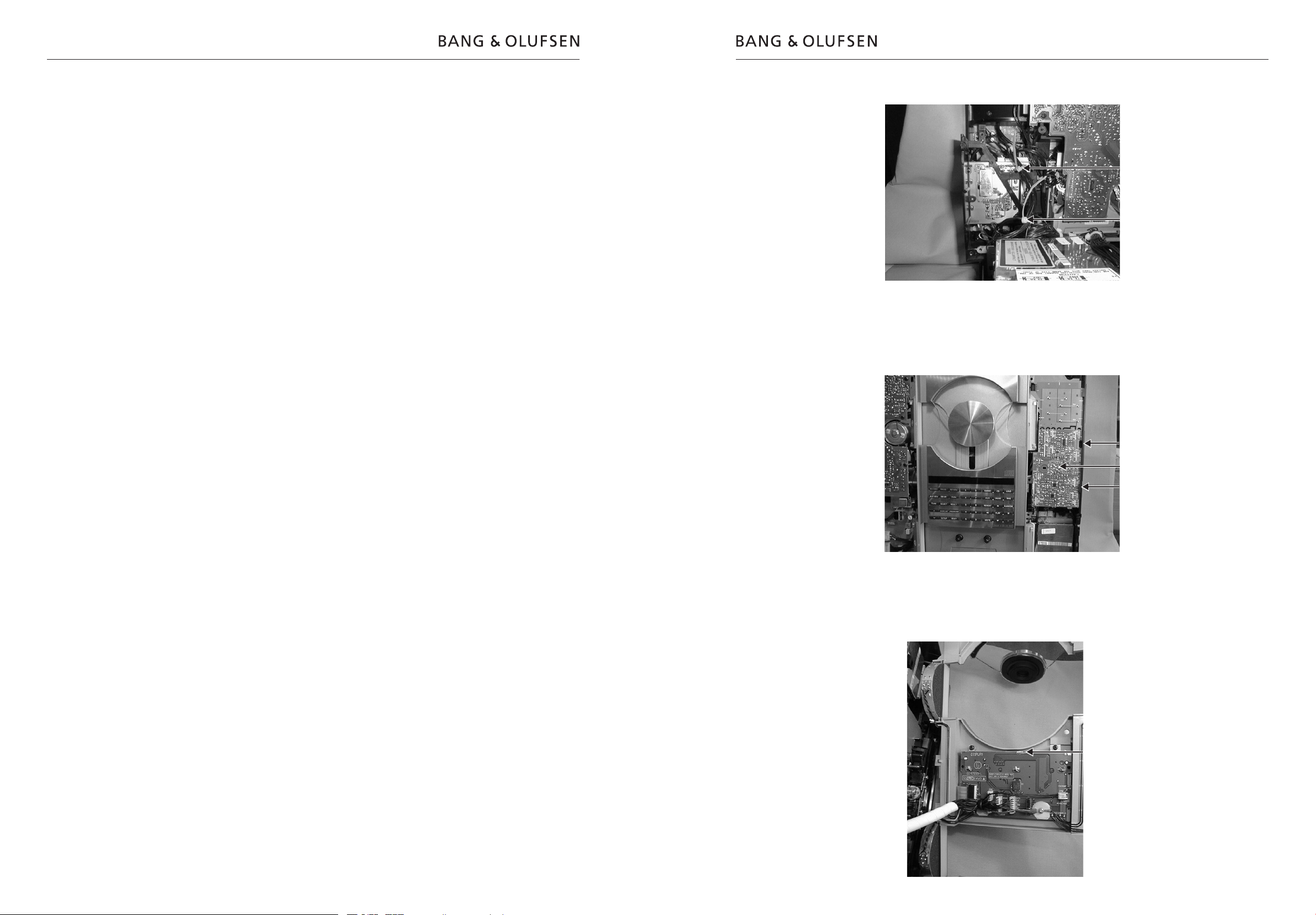
- Ledningerne til 87P65 & 87P66 samles med strips (se
billed. 1).
- Monter ledningerne mellem: 87P65-2P15
87P66-2P12
87P67-2P11
87P68-3P30
- Monter PCB87 (se billed. 2). Printet skal være placeret således, at der er plads til låsetappene fra
frontstykkerne.
- Værdierne på følgende komponenter, på powersupply PCB2, skal være:
2C115/12C77 470µF 25V 20% koordinat 1A
2R164/12R74 180 ohm 1/4W 1% koordinat 1A
2R165/12R143 15K ohm 1/8W 5% koordinat 1A
7C13 skal være fysisk lav, som den medsendte.
- Monter det nye CD-chassis (9037).
- Monter de nye ledtninger mellem løbeværk og
PCB87 (bestillings nr. 6277019), ledningerne skal
føres igennem det nye CD-chassis.
1217 - 87P207 240mm 4 leder
1214 - 87P200 140mm 4 leder
1004 - 87P204 240mm 6 leder
- Fjern PCB20, Disc Detector.
- Monter det nye CD-løbeværk/PCB. Brug de medfølgende skruer(1).
- Monter det nye Cover (9032) der passer til tangentialarm.
- Ret den midterste tap ud, øverst på holder 0506, bøj
tappen således, tat den ligger helt ind til printet, for
at give plads til det nye CD-løbeværk. (Se billed. 3).
- Monter Keyboard/display, sidepanelerne og afprøv
apparatet.
- Service Manualen der henvises til har bestillings nr.
3538922 BeoCenter 2300/2500
3538926 MasterPanel AV9000
3538933 BeoSound Ouveture.
Komponent liste:
2C115 4201256 470µF 25V 20%
2R164 5011903 180 ohm 1/4W 1%
2R165 5011189 15K ohm 1/8W 5%
1 2038133 Screw, 3x11
9037 3112418 Chassis
9032 3162461 Cover
Wire 6277019 Wire bundle
CD mech. 8420262 CD-PRO II / PCB87
3162652 Clamper
3542182C 09-03
Replacement of CDM4 for the CD-PRO II mechanism in BeoCenter 2300 / 2500 / MPAV9000 / BeoSound Ouverture
- Disassemble the product so that it is ready for
replacement of the CD mechanism (see page 7-1 of
the Service Manual).
- Remove the old CD mechanism.
- Remove the side panels.
- Remove PCB8. (CD mechanism + PCB87 replace PCB8.)
- Release the leads from 08P65 and 08P66 from the
main lead bundle until they are able to reach the
new PCB87.
- Assemble the leads for 87P65 and 87P66 with strips
(see picture 1).
- Install the leads between: 87P65-2P15
87P66-2P12
87P67-2P11
87P68-3P30
- Install PCB87 (see picture 2). The circuit board must
be placed in such a way that it provides sufcient
space for the locking pins from the front pieces.
- The values of the following components on the
power supply, PCB2, should be as follows:
2C115/12C77 470µF 25V 20% coordinate 1A
2R164/12R74 180 ohm 1/4W 1% coordinate 1A
2R165/12R143 15K ohm 1/8W 5% coordinate 1A
7C13 must be physically low as the one enclosed.
- Install the new CD chassis (9037).
- Install the new leads between C mechanism and
PCB87 (part no. 6277019), the leads must be run
through the new CD chassis.
1217 - 87P207 240mm 4 conductors
1214 - 87P200 140mm 4 conductors
1004 - 87P204 240mm 6 conductors
- Remove PCB20, Disc Detector.
- Install the new CD mechanism/PCB. Use the screws
enclosed (1).
- Install the new cover (9032) tting the tangential arm.
- Straighten out the middle pin, at the top of holder
0506, bend the pin in such a way that it is completely
ush with the circuit board in order to provide sufcient space for the new CD mechanism. (See picture
3.)
- Install the keyboard/display and the side panels, and
test the product.
- The Service Manual referred to has part no.
3538922 BeoCenter 2300/2500
3538926 MasterPanel AV9000
3538933 BeoSound Ouveture.
Components list:
2C115 4201256 470µF 25V 20%
2R164 5011903 180 ohm 1/4W 1%
2R165 5011189 15K ohm 1/8W 5%
1 2038133 Screw, 3x11
9037 3112418 Chassis
9032 3162461 Cover
Wire 6277019 Wire bundle
CD mech. 8420262 CD-PRO II / PCB87
3162652 Clamper
Replacement of CDM4 for the CD-PRO II mechanism.
Type 260x - 261x - 262x - 263x 3210017
Austausch von CDM4 für CD-PRO II Laufwerk in
BeoCenter 2300 / 2500 / MPAV9000 / BeoSound
Ouverture.
- Das Gerät so zerlegen, daß das Laufwerk ausgetauscht werden kann (siehe hierzu das Service
Manual Seite 7-1).
- Das alte Laufwerk ausbauen.
- Die Seitenpanele demontieren.
- PCB8 entfernen (Laufwerk + PCB87 ersetzen PCB8).
- Die Leitungen von 08P65 und 08P66 sind aus dem
Hauptleitungsbündel herauszulösen, so daß sie die
neue Platine, PCB87, erreichen können.
- Die Leitungen für 87P65 und 87P66 sind mit Strips
zusammenzufassen (siehe Bild 1).
- Die Leitungen montieren zwischen: 87P65-2P15
87P66-2P12
87P67-2P11
87P68-3P30
- PCB87 montieren (siehe Bild 2). Die Platine ist so
anzubringen, daß die Verrielungslaschen von den
Frontstücken genügend Platz haben.
- Die nachstehenden Komponenten auf dem ‚Power
Supply‘- PCB2 haben folgende Werte aufzuweisen:
2C115/12C77 470µF 25V 20% Koordinate 1A
2R164/12R74 180 Ohm 1/4W 1% Koordinate 1A
2R165/12R143 15K Ohm 1/8W 5% Koordinate 1A
7C13 muss physisch niedrig sein, wie die mitges-
chickte
- Das neue CD-Chassis (9037) montieren.
- Die neuen Leitungen zwischen Laufwerk und PCB87
montieren (Bestell-Nr. 6277019); die Leitungen sind
durch das neue CD-Chassis hindurchzuführen:
1217 - 87P207 240 mm 4-adrig
1214 - 87P200 140 mm 4-adrig
1004 - 87P204 240 mm 6-adrig
- PCB20, ‚Disc Detector‘, entfernen.
- Das neue CD-Laufwerk/PCB montieren. Die mitgelieferten Schrauben (1) benutzen.
- Den neuen Deckel (9032) passend zum TangentialArm montieren.
- Zuerst den mittleren Zapfen oben am Halter 0506
geradebiegen und anschließend dann so verbiegen, daß
er vollkommen an die Platine zu liegen kommt und so
dem neuen CD-Laufwerk Platz macht. (Siehe Bild 3).
- Keyboard/Display und die Seitenpanele montieren
und das Gerät testen.
- Das Service Manual, auf das Bezug genommen wird,
hat die Bestell-Nr.
3538922 BeoCenter 2300/2500
3538926 MasterPanel AV9000
3538933 BeoSound Ouveture.
Die Komponentenliste:
2C115 4201256 470µF 25V 20%
2R164 5011903 180 ohm 1/4W 1%
2R165 5011189 15K ohm 1/8W 5%
1 2038133 Screw, 3x11
9037 3112418 Chassis
9032 3162461 Cover
Wire 6277019 Wire bundle
CD mech. 8420262 CD-PRO II / PCB87
3162652 Clamper
Remplacement de la platine CDM4 du
BeoCenter 2300 / 2500 / MPAV9000 / BeoSound
Ouverture par le mécanisme CD-PRO II
- Désassembler l’appareil pour pouvoir remplacer le
mécanisme (voir manuel de maintenance, page 7-1).
- Déposer l’ancien mécanisme.
- Déposer les joues.
- Enlever la carte PCB8 (mécanisme et PCB87 remplacent PCB8).
- Dégager du faisceau de câbles principal les ls
venant de 08P65 et de 08P66 pour qu’ils puissent
atteindre la nouvelle carte (PCB87).
- A l’aide d’attaches, remettre en place les ls reliés à
89P65 et à 89P66 (voir gure 1).
- Brancher les ls reliant: 87P65 et 2P15
87P66 et 2P12
87P67 et 2P11
87P68 et 3P30
- Monter la carte PCB87 (voir gure 2). La positionner
en ménageant une place sufsante pour les ergots
des panneaux frontaux.
- Les composants ci-dessous doivent présenter les
valeurs suivantes sur la carte PCB2 («Power Supply»):
2C115/12C77 470µF 25V 20% coordonnées 1A
2R164/12R74 180 Ohm 1/4W 1% coordonnées 1A
2R165/12R143 15K Ohm 1/8W 5% coordonnées 1A
7C13 doit être aussi petit que le composant joint.
- Monter le nouveau châssis CD (9037).
- Brancher les nouveaux ls reliant les cartes PCB80
et PCB87 (réf. 6277019). Faire passer les ls dans le
nouveau châssis CD.
1217 - 87P207 240 mm 4 conducteurs
1214 - 87P200 140 mm 4 conducteurs
1004 - 87P204 240 mm 6 conducteurs
- Déposer la carte PCB20 («Disc Detector»).
- Monter le nouveau mécanisme d’entraînement du
CD et la carte PCB. Utiliser les vis jointes (1).
- Monter le nouveau couvercle (9032) adapté au bras
tangentiel.
- Redresser le doigt central (au-dessus du support
0506), puis le replier pour qu’il touche bien la carte
et permette ainsi de loger le nouveau mécanisme
d’entraînement du CD (voir gure 3).
- Remonter le clavier, l’afcheur et les joues. Tester
l’appareil.
- Le manuel de maintenance correspondant est
référencé
3538922 BeoCenter 2300/2500
3538926 MasterPanel AV9000
3538933 BeoSound Ouveture.
Nomenclature des composants:
2C115 4201256 470µF 25V 20%
2R164 5011903 180 ohm 1/4W 1%
2R165 5011189 15K ohm 1/8W 5%
1 2038133 Screw, 3x11
9037 3112418 Chassis
9032 3162461 Cover
Wire 6277019 Wire bundle
CD mech. 8420262 CD-PRO II / PCB87
3162652 Clamper
Figure 1
Strips
Strips
Figure 2
PCB87
Figure 3
0506
 Loading...