

Page 1
Service menu, English 5.5
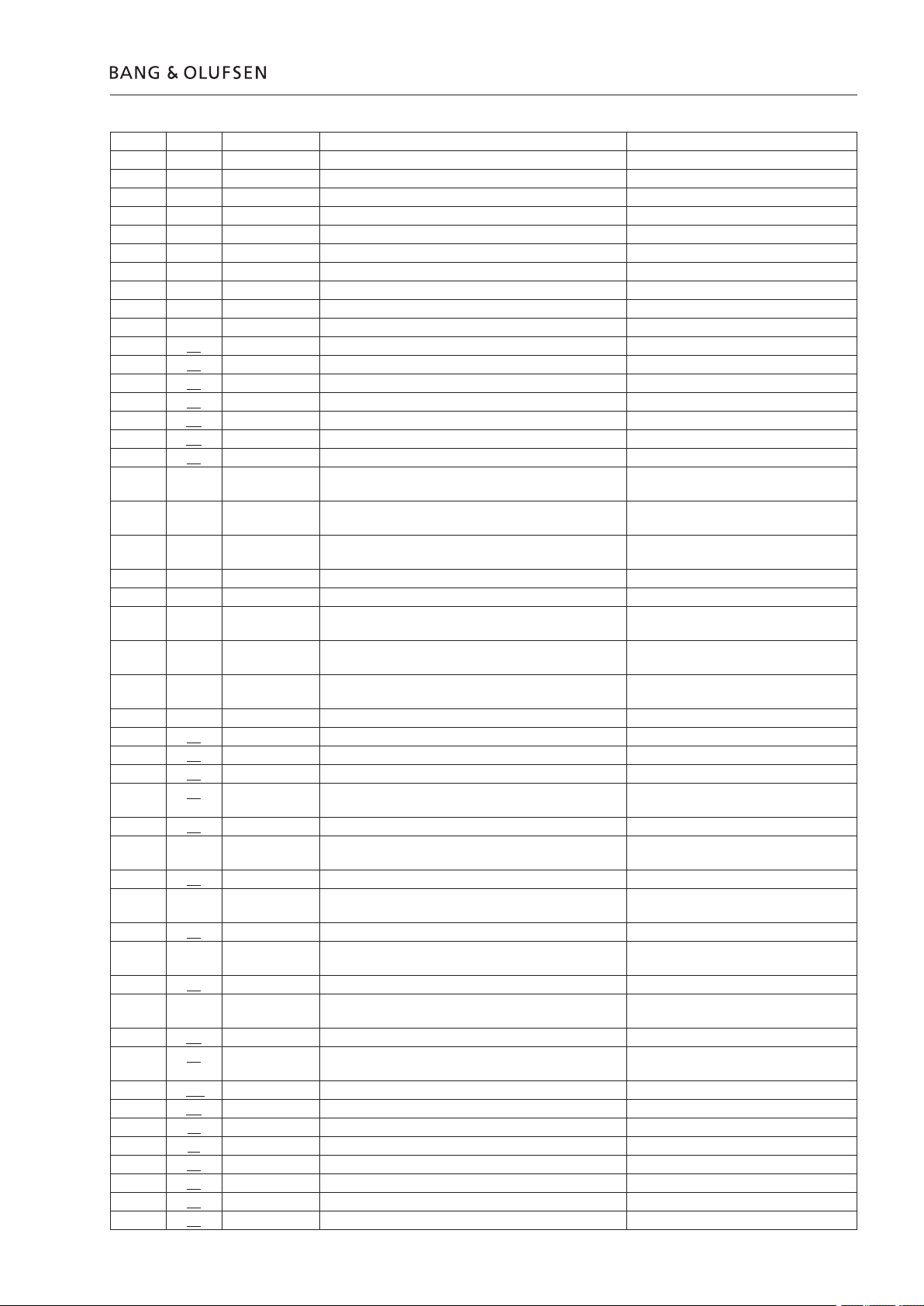
EP 1 = 08 IIC1 2 ICB ERROR Use EP2
EP 2 = D0 CLOCK IIC ADDR (IC162) Av Panel
EP 2 = 88 A ENG IIC ADDR (IC300) Analog Sound Engine
EP 2 = 22 ST RDS IIC ADDR (IC402) Tuner
EP 2 = C6 ST TUNER IIC ADDR (IC200) Tuner
EP 2 = C4 ST PLL IIC ADDR (IC200) Tuner
EP 2 = 8C ST STEREO DECODER IIC ADDR (IC300) Tuner
EP 2 = 7E ST LPC IIC ADDR (IC401) Tuner
EP 2 = A0 ST EEPROM ADDR (IC203) Tuner
EP 3 = 00 IIC1 BUS ID IIC bus no. for e.g. measurements
EP 3 = 01 IIC2 BUS ID IIC bus no. for e.g. measurements
02 Eeprm addr EEPROM WRITE ERROR Default settings or replace EEPROM
03 Eeprm addr EEPROM READ ERROR Default settings or replace EEPROM
04 Eeprm addr EEPROM READ ERROR ONLY FF Default settings or replace EEPROM
0B Eeprm addr EE WRITE OVERFLOW Default settings or replace EEPROM
0C Eeprm addr EE CONTROL INIT FAIL Default settings or replace EEPROM
0D Eeprm addr EE CONTROL CALLOC FAIL Default settings or replace EEPROM
20 MLSL STATUS ERROR
EP 1 = 20 CONFIG IMPOSS ML installation, Analog Sound Engine, or
EP 1 = 10 LINK TIED UP ML installation, Analog Sound Engine, or
EP 1 = 08 LINK TIED DOWN ML installation, Analog Sound Engine, or
EP 1 = 04 LINK OK No error
EP 1 = 02 ML CURRENT MASTER No error
EP 1 = 22 CONFIG IMPOSS CURRENT MASTER ML installation, Analog Sound Engine, or
EP 1 = 12 LINK TIED UP CURRENT MASTER ML installation, Analog Sound Engine, or
EP 1 = 02 LINK TIED DOWN CURRENT MASTER ML installation, Analog Sound Engine, or
EP 1 = 06 LINK OK AND CURRENT MASTER No error
21 MLSL TIMEOUT ERROR No error
22 MLSL TX BUF FULL TLG NOT SEND No error
23 ML KEY LOST KEY REPAIRED No error
24 EXTERNAL COMMUNICATION NOT ALLOWED IN
PREPROJECT
25 LSL FORMAT ERROR
EP 1 = 00 LSL1 ERROR ID Defect Scart or CTRL. Connection, or
27 LSL TX IMPOSS
EP 1 = 00 LSL1 ERROR ID Defect Scart or CTRL. Connection, or
28 LSL LINK TIED UP
EP 1 = 00 LSL1 ERROR ID Defect Scart or CTRL. Connection, or
29 LSL LINK TIED DOWN
EP 1 = 00 LSL1 ERROR ID Defect Scart or CTRL. Connection, or
2A GENERIC ICB ERROR uP H8 Module
2B ICB L7 TIMEOUT ML installation, Analog Sound Engine, Av
2C ICB L7 ILLEGAL TIMEOUT uP H8 Module
2D ICB L7 OUT OF REPOSITORIES uP H8 Module
2E ICB L7 ILLEGAL L7 ACK uP H8 Module
2F ICB L7 AKNOWLADGE UNEXPECTED uP H8 Module
30 ICB L7 READ RESPONSE UNEXPECTED uP H8 Module
31 ICB L7 ILLEGAL RESOURCE TYPE uP H8 Module
32 ICB L7 RESOURCE STILL RUNNING uP H8 Module
33 ICB L7 RESOURCE ALLREADY FREE uP H8 Module
Av Panel
Av Panel
Av Panel
Av Panel
Av Panel
Av Panel
No error
(IC300) Av Panel
(IC300) Av Panel
(IC300) Av Panel
(IC300) Av Panel
Panel, or uP H8 Module
Page 2
5.6 Service menu, English
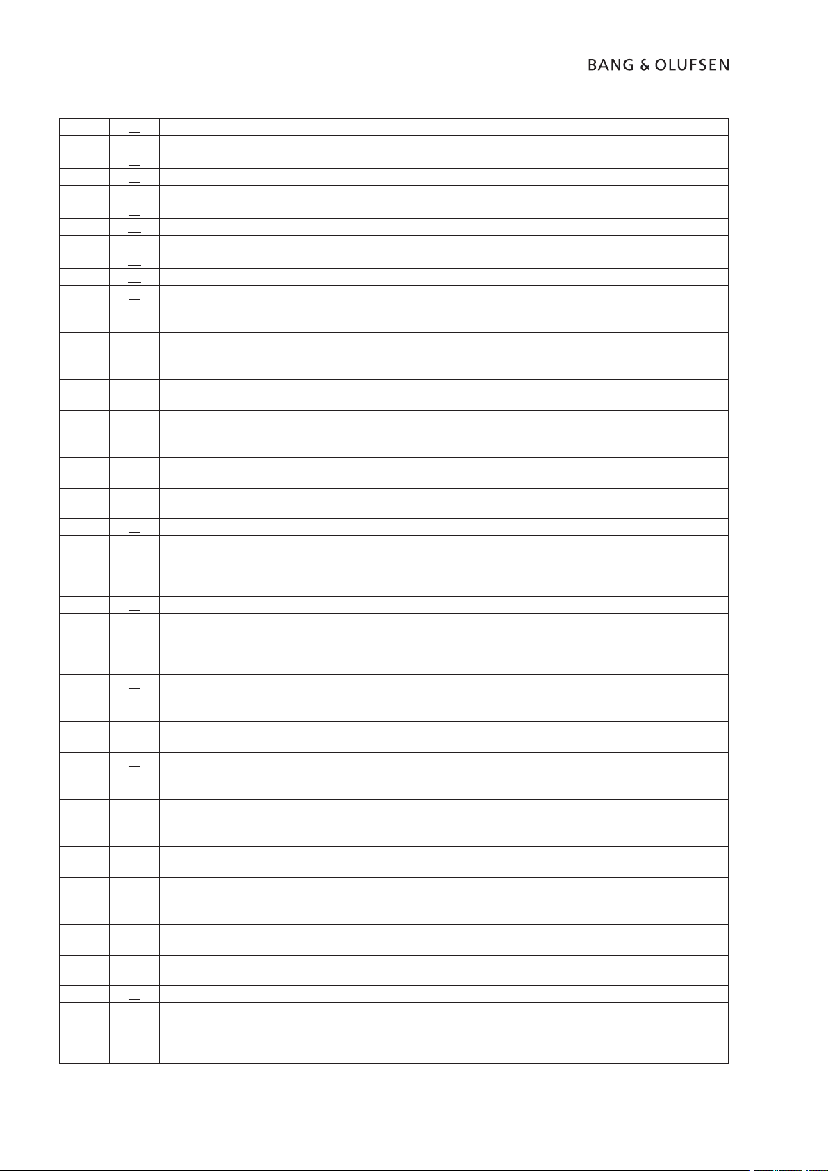
34 ICB L7 ILLEGAL IOP SERVICE uP H8 Module
35 ICB L7 ILLEGAL IOP OBJECT uP H8 Module
36 ICB L7 TELEGRAM FLUSHED uP H8 Module
37 ICB L7 RESOURCE DISABLED uP H8 Module
38 ICB L7 HW CLOCK ILLEGAL COMMAND uP H8 Module
39 ICB L7 HW CLOCK ILEGAL EVENT uP H8 Module
3A ICB L2 RETRANS LIMIT REACHED uP H8 Module
3B IIC COMPONENT DISABLED uP H8 Module
3C POWER DOWN OF IOP IMPOSSIBLE uP H8 Module
3D CSD BUS DISABLED SW bug, check for AP SW update
3F ATI OVERRUN ERROR
EP 1 = 00 Av Panel or Connection between Socket
EP 1 = 01 Av Panel, Top Interface, or interface cable
40 ATI NACK
EP 1 = 00 Av Panel or Connection between Socket
EP 1 = 01 Av Panel, Top Interface, or interface cable
41 ATI NACK NO BUF
EP 1 = 00 Av Panel or Connection between Socket
EP 1 = 01 Av Panel, Top Interface, or interface cable
42 ATI NACK BAD SEQ
EP 1 = 00 Av Panel or Connection between Socket
EP 1 = 01 Av Panel, Top Interface, or interface cable
43 ATI NACK OVERRUN
EP 1 = 00 Av Panel or Connection between Socket
EP 1 = 01 Av Panel, Top Interface, or interface cable
44 ATI UNKNOWN PROTOCOL
EP 1 = 00 Av Panel or Connection between Socket
EP 1 = 01 Av Panel, Top Interface, or interface cable
45 ATI TIMEOUT NO RESPONSE
EP 1 = 00 Av Panel or Connection between Socket
EP 1 = 01 Av Panel, Top Interface, or interface cable
46 ATI DRIVER DISABLED
EP 1 = 00 Av Panel or Connection between Socket
EP 1 = 01 Av Panel, Top Interface, or interface cable
47 ATI UART DONT EXIST
EP 1 = 00 Av Panel or Connection between Socket
EP 1 = 01 Av Panel, Top Interface, or interface cable
48 ATI BREAK SYNC ABORTED
EP 1 = 00 Av Panel or Connection between Socket
EP 1 = 01 Av Panel, Top Interface, or interface cable
‘Yellow’
‘Blue’
‘Green’
‘Red’
‘Yellow’
‘Blue’
‘Green’
‘Red’
‘Green’
‘Yellow’
Unit and Test equipment
(connection or cable)
Unit and Test equipment
(connection or cable)
Unit and Test equipment
(connection or cable)
Unit and Test equipment
(connection or cable)
Unit and Test equipment
(connection or cable)
Unit and Test equipment
(connection or cable)
Unit and Test equipment
(connection or cable)
Unit and Test equipment
(connection or cable)
Unit and Test equipment
(connection or cable)
Unit and Test equipment
(connection or cable)
Page 3
F8
Service menu, English 5.7
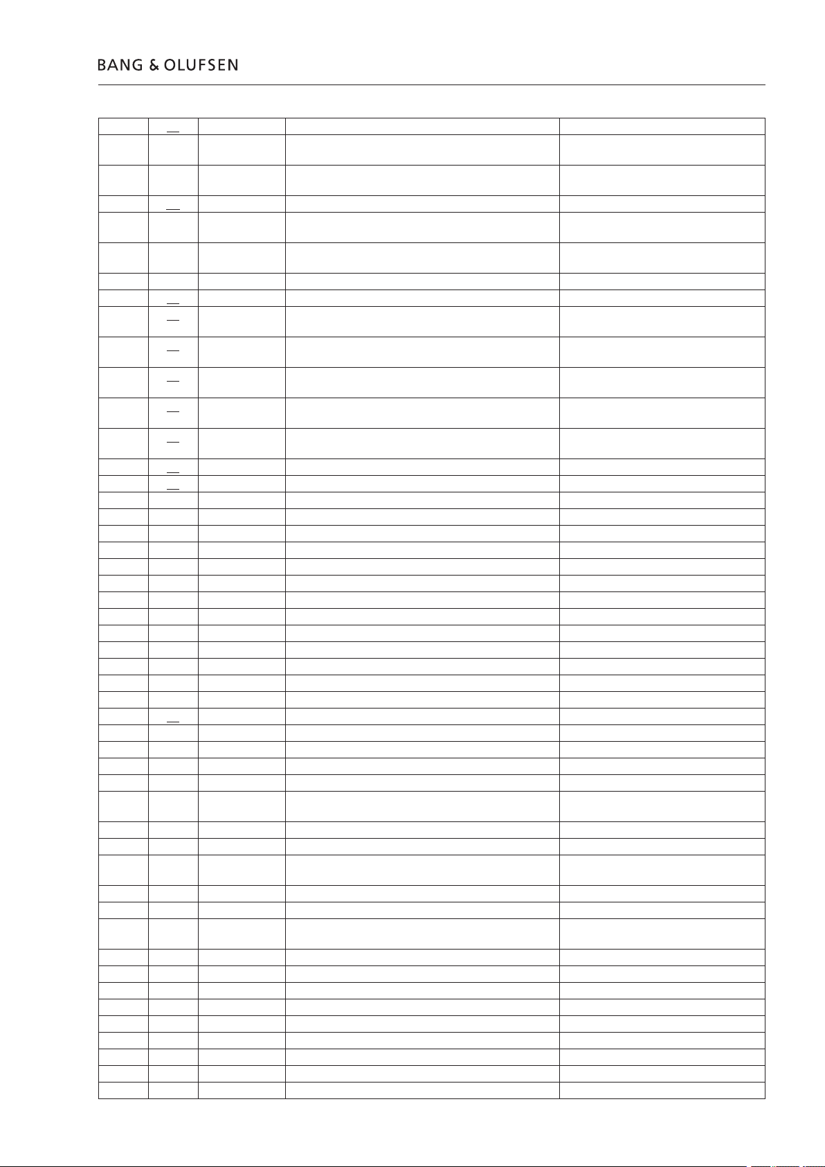
49 ATI NO TX ALLOWED
EP 1 = 00 Av Panel or Connection between Socket
Unit and Test equipment
EP 1 = 01 Av Panel, Top Interface, or interface cable
(connection or cable)
4A ATI TLG WAS BREAK SYNCHED
EP 1 = 00 Av Panel or Connection between Socket
Unit and Test equipment
EP 1 = 01 Av Panel, Top Interface, or interface cable
(connection or cable)
APPLICATION ERROR
00 NO APPLICATION ERROR No error
01 ILLEGAL TOP FEP TELEGRAM SW bug, check for Master Unit/AP SW
update
02 INVALID KEY EVENT SW bug, check for Master Unit SW
update
10 POWER FAIL 50MS Power disconnected while BC2 not in
stanby, or SMPS
11 POWER FAIL 100MS Power disconnected while BC2 not in
stanby, or SMPS
20 TRANSMISSION BUFFER TIMEOUT SW bug, check for Master Unit SW
update
21 ILLEGAL PORT VALUE Test equipment used wrong port value
30 TUNER ERROR
EP 1 = 02 RDS COMPONENT (IC402) Tuner
EP 1 = 03 TUNER COMPONENT (IC200) Tuner
EP 1 = 04 PLL COMPONENT (IC200) Tuner
EP 1 = 05 STEREO DECODER COMPONENT (IC300) Tuner
EP 1 = 06 LPC COMPONENT (IC401) Tuner
EP 1 = 07 ST EEPROM COMPONENT (IC203) Tuner
EP 2 = 00 NO ST ERROR Use EP1
EP 2 = 01 ST WRITE ERROR Use EP1
EP 2 = 02 ST READ ERROR Use EP1
EP 2 = 03 ST CHKSUM ERROR Use EP1
EP 2 = 04 ST READ ERROR ONLY FF Use EP1
EP 2 = 05 ST BLOCK LIMIT Use EP1
EP 2 = 06 ST EEPROM INVALID BLOCK Use EP1
40 RMP STATUS ERROR
EP 1+2 = 0001 RMP START UP MEDIA Use EP3
EP 3 = 01 RMP NO DISC No error
EP 3 = 02 RMP INVALID MEDIA TYPE No error
EP 3 = 03 RMP SUBCODE ERROR No error
EP 3 = 04 RMP START UP TIMEOUT DVDM, SW bug check for Master Unit
SW update
EP 3 = 05 RMP TOC ERROR No error
EP 3 = 1E RMP DOORS NOT CLOSED SW bug, check for AP SW update
EP 3 = 20 RMP DRIVER NOT STARTED SW bug, check for Master Unit SW
update
EP 1+2 = 0002 RMP GOTO TRACK Use EP3
EP 3 = 06 RMP INVALID TRACK NO No error
EP 3 = 07 RMP TRACK NOT FOUND TIMEOUT DVDM, SW bug check for Master Unit
SW update
EP 1+2 = 0003 RMP STOP Use EP3
EP 3 = 08 RMP STOP TIMEOUT No error
EP 1+2 = 0004 RMP PAUSE Use EP3
EP 3 = 09 RMP PAUSE TIMEOUT No error
EP 1+2 = 0005 RMP PAUSE RELEASE Use EP3
EP 3 = 0A RMP PAUSE RELEASE TIMEOUT No error
EP 1+2 = 0006 RMP WIND Use EP3
EP 3 = 0B RMP WIND TIMEOUT No error
EP 1+2 = 0007 RMP REWIND Use EP3
Page 4

5.8 Service menu, English
EP 3 = 0C RMP REWIND TIMEOUT No error
EP 1+2 = 0008 RMP RESET ALL Use EP3
EP 3 = 0D RMP RESET TIMEOUT No error
EP 1+2 = 0009 RMP MUTE Use EP3
EP 3 = 0E RMP MUTE TIMEOUT No error
EP 1+2 = 000A RMP DEMUTE Use EP3
EP 3 = 0F RMP DEMUTE TIMEOUT No error
EP 1+2 = 000B RMP RELEASE WIND REWIND Use EP3
EP 3 = 10 RMP RELEASE WIND REWIND TIMEOUT No error
EP 1+2 = 000C RMP MARK A Use EP3
EP 3 = 11 RMP MARK A ERROR TIMEOUT No error
EP 1+2 = 000D RMP MARK B Use EP3
EP 3 = 12 RMP MARK B ERROR TIMEOUT No error
EP 1+2 = 000E RMP RELEASE AB Use EP3
EP 3 = 13 RMP AB REPEAT ERROR TIMEOUT No error
EP 1+2 = 000F RMP GOTO ABS TIME No error
EP 1+2 = 0012 RMP FOLDER STEP Use EP3
EP 3 = 1C RMP FOLDER STEP TIMEOUT No error
EP 1+2 = 0023 RMP SHUTDOWN MEDIA No error
EP 3 = 1D RMP SHUTDOWN MEDIA TIMEOUT DVDM, SW bug check for Master Unit
EP 1+2 = 0024 RMP QUEUE NEXT TRACK No error
EP 3 = 06 RMP INVALID TRACK NO No error
EP 3 = 07 RMP TRACK NOT FOUND TIMEOUT DVDM, SW bug check for Master Unit
EP 1+2 = 0105 RMP START DRIVER Use EP3
EP 3 = 22 RMP START DRIVER TIMEOUT DVDM
EP 3 = 00 RMP NO RMP ERROR No error
EP 3 = 17 RMP COMMUNICATION ERROR SW bug, check for Master Unit/AP SW
EP 3 = 1E RMP DOORS NOT CLOSED Check door and loader mechanics, SW
EP 3 = 20 RMP DRIVER NOT STARTED SW bug, check for Master Unit/AP SW
EP 3 = 21 RMP BUSY No error
41 RMP TRANSMIT QUEUE FULL SW bug, check for AP SW update
42 RMP DD UNKNOWN COMMAND SW bug, check for Master Unit SW
50 OUT OF DISPLAY REPOSITORIES SW bug, check for AP SW update
51 DISPLAY REPOSITORY OVERRUN SW bug, check for AP SW update
60 CABLE DATA UNSTABIL Check connection between Socket Unit
61 PING PONG FAILURE Check connection between Socket Unit
62 TOP RETRANS FAILED Check connection between Socket Unit
70 DOORS BLOCKED OPENING Check doors mechanical
71 DOORS BLOCKED CLOSING Check doors mechanical
72 DOORS NOT READY ERROR Check doors mechanical
73 SOF DISP EXCEED SOF DISP DD TELEGRAM TYPE SW bug, check for AP SW update
74 OUT OF DISP DD TELEGRAMS SW bug, check for Master Unit SW
75 TOP ERROR
EP 1 = 00 BRC NOT COMPLETED Check connection between Socket/
EP 1 = 01 DENIED BRC REQUEST Check connection between Socket/
SW update
SW update
update
bug check for Master Unit SW update
update
update
and Master Unit, AV Panel, Top interface,
interface cable.
and Master Unit, AV Panel, Top interface,
interface cable.
and Master Unit, AV Panel, Top interface,
interface cable.
update
Master Unit, AV Panel, Top interface,
interface cable
Master Unit, AV Panel, Top interface,
interface cable
Page 5

Service menu, English 5.9
3. Product ID
EP 1 = 02 BRC DENIED Check connection between Socket/
Master Unit, AV Panel, Top interface,
interface cable
EP 1 = 09 CABLE DATA UNSTABIL Check connection between Socket/
Master Unit, AV Panel, Top interface,
interface cable
EP 1 = 11 PIO CMD QUEUE FULL SW bug, check for Master Unit SW
update
EP 1 = 12 ATI CI QUEUE FULL SW bug, check for Master Unit SW
update
EP 1 = 13 DVD COMM TIMO DVDM
When leaving the NVMEM Error List menu user is prompted to clear the list.
...NVMEM
Clear Error List?
Clear Keep
^-------------
Select Clear to permanently delete the list, or Keep to not delete the list.
...Product ID
1 Item No xxxxxxx
2 Type No YYYYYYYY
3 Serial No zzzz
4 PIN OK
4. Service Counters
If Error in Master PIN code PIN = Err, else PIN = OK.
...Service Counters
1 Time Standby 1100
2 Time Radio 10
3 Time CD 5
4 Time DVD 23
5 Time AUX 0
6 Time active ML 2
7 Time TP Enabled 3
8 Times Standby 3
9 Times Booted 23
*NOTE: Unit of Time is in *10hours
Time Standby: Time unit is placed in standby x10hours
Time Radio: Time Radio source is active x10hours
Time CD: Time CD source is active x10hours
Time DVD: Time DVD source is active x10hours
Time AUX: Time AUX source is active x10hours
Time active ML: Time source from ML is active x10hours
Time TP Enabled: Time unit has TP enabled x10hours
Times Standby: Times the unit is placed in standby
Times Booted: Times the uP is booted (times disconnected/connected from mains)
Page 6

5.10 Service menu, English
5.Default Settings
6.Keyboard Test
...Default Settings
Set Default Settings?
Yes No
^------
...Keyboard Test
Key: CNTL_STEP_UP_KEY
Data: 0
Valid Key Names are
CIFFER_0_KEY
CIFFER_1_KEY
CIFFER_2_KEY
CIFFER_3_KEY
CIFFER_4_KEY
CIFFER_5_KEY
CIFFER_6_KEY
CIFFER_7_KEY
CIFFER_8_KEY
CIFFER_9_KEY
STEP_UP_KEY
STEP_DW_KEY
WIND_KEY
REWIND_KEY
GO_KEY
CNTL_WIND_KEY
CNTL_REWIND_KEY
CNTL_STEP_UP_KEY
CNTL_STEP_DW_KEY
DISC_KEY
RADIO_KEY
MENU_KEY
LOAD_KEY
STANDBY_KEY
EXIT_KEY
VOLUME_KEY
7. Loader Lock
For VOLUME_KEY the Data eld is also used.
Data show the last data different from 0 received for a VOLUME_KEY
...Keyboard Test
Key: VOLUME_KEY
Data: +4
The Data indicate the NOF steps the volume would be regulated during normal
operation.
To leave the Keyboard Test press T (Beo4).
This menu can lock Unlock the Loader.
When the Loader is Locked the unit will not open loader and clamper, upon a
LOAD key, used so CD’s/DVD’s aren’t stolen in shops.
...Loader Lock
Current Mode: Unlocked
Unlocked Locked
^---------------
*NOTE: Loader Lock is Default Unlocked
Page 7

8. DVD Service
201B8964 R -
TRKG
M- 08 S - 00
K-
V- AUTO
SK AV : BO / 1D415041
FL : 0.0 REG: 02
MDL : UDVD / WY
VYW2122
V : 1.128_Ad-FLASH :08
S : 4.1 / 661
M : 1 / 10
SPDL
DSC - DVD
J - 0000001A
1
2
3
5
6
7
8
9
10
11
12
13
14
15
16
17
18
19
Service menu, English 5.11
While playing DVD with the BeoCenter 2, you are able to recall a Pioneer service
menu, onscreen.
When entering this menu the BEO4 IR codes is send to the MasterUnit which
translate this in to Pioneer Test IR codes.
...DVD Service
Enter IR Command
While the DVD is playing, and you are in “DVD service” press “Yellow” and then
“Blue” on the BEO4 (remote should be in “CD” mode)
Now a onscreen service menu is displayed (it can be necessary to put the television
into format 1 to view the full onscreen menu)
1. Address indication
2. Code indication of remote control unit
3. Main unit keycode indication
5. Tracking status (on/off)
See the status on the tracking, is the feature on or off.
6. Spindle status (off, a/b, acc/brk, cav, clv)
7. Mechanism (loading) position value
Unknown : 01 or 41
Open state : 04
Close state : 08
During opening : 12
During closing : 22
8. Slider position
If the mechanism has stopped, you are able to see in
what position the laser do fail, or in which section
the disc is bad.
CD TOC area : IN
CD active area : CD
9. Output video system (NTSC, PAL, AUTO)
10. Disc sensing (DVD, CD, VCD)
This tell you what format the inserted disc is.
11. Jitter value
This is a statement of the current jitter value, it gives
you an instant quality description of the disc, while it
plays.
12. Version of the AV-1 chip/version of rmware
The version of the chip and of the software can be
read out here.
13. Version of the FL controller
14. Region setting of the player (1 to 6)
You are able to see what Region code the Master
Unit is locked too, useful when you have changed
the socket unit, or are reprogramming the Master
Unit to a new country.
15. Destination setting of the FL controller
16. Part number of the ash ROM
17. Version of the Flash ROM (V:)/Flash ROM size (FLSH =)
18. Revision of the system controller
19. Revision of the DVD mechanism controller
Page 8

xxxxxxxxx 5.13
5.12
Service menu, English
Replacement of modules
Master unit
Modules See page
Keyboard, left 6.1
Keyboard, right 6.2
Display 6.3
Display PCB 6.4
IR receiver one (left) 6.5
IR receiver two (right) 6.6
Clamper 6.7
Clamper cover 6.8
Socket unit
Modules See page
PCB50 Analogue Sound engine 6.19
PCB86 Tuner 6.20
PCB60 Switch mode power supply 6.21
PCB6 Microprocessor H8 6.22
PCB1 A/V panel 6.23
Replacing the Main microcomputer PCB6 (uPH8)
When replacing the PCB6 remember to move the EEPROM 6IC6 from the
defective PCB6 to the new PCB6, because it contains valuable data (Serial no., PINcode etc.).
Modules See page
Gear box 6.9
DVD mechanism 6.10
DVD main board 6.11
Top Interface 6.12
Rubber belt 6.13
Clamper motor 6.14
Gearbox rubber belt 6.15
Gearbox motor 6.16
Note !
ServiceTool
The data is not transferred to the new module until you have been in contact with
the theft protection or after 12 hours of connection to the mains. This means that
you can try out a new PCB6 without transferring the products serial no. Etc.
If you have tried a new PCB6 and the serial no. has been transferred to the new
PCB6 and it says that the old PCB6 is not defective, the new PCB6 can only be
used for this specic product, it must be returned to Bang & Olufsen to be erased
again. If the product functions are OK, and the theft protection is also OK. There is
no need to testing the functionality of the theft protection.
Replacing of both PCB6 and EEPROM 6IC6
If both PCB6 and the EEPROM 6IC6 need to be replaced it is necessary to have
them pre-programmed from Bang & Olufsen with the correct serial no., otherwise
they will not work. Please contact Bang & Olufsen.
Along with a “cable kit for ServiceTool” (3375397) and “Flash kit for ServiceTool”
(3375055) it is possible to ash update the Pioneer FEP software, and the Master
Unit FEP software. The original interface cable is connected to the Master Unit,
and is going to a service module. From this module a special service cable goes to
the Socket Unit. From the service module goes another service cable to a laptop.
On the service module, you are able to select which software you want to ash
update via a switch. You will need to get the ServiceTool program installed on your
lab-top, this can be ordered on CDROM (3658949) or downloaded from the Retail
Business System. A fully described instruction is enclosed when the “Flash kit for
ServiceTool” is ordered (3375055).
Page 9

Replace Keyboard left
Socket Unit
Replace Keyboard left
6.1
1
2
4
5
3
180º
Page 10

Socket Unit
6.2
Replace Keyboard right
Replace Keyboard right
1
4
2
3
5
180º
 Loading...