

Page 1

User
Manual
BandLuxe
E600 Series
LTE Advanced Outdoor
CPE
P/N: 65029900011 Rev. A
Page 2

Page 3

Table of Contents
Product Overview ........................................................................... 4
Features .................................................................................................................. 4
Package Contents ................................................................................................... 4
Hardware Overview ................................................................................................. 5
Installation....................................................................................... 7
Notice before installation ......................................................................................... 7
Important Installation Considerations ...................................................................... 8
Mounting the Unit .................................................................................................... 9
Ground the CPE ...................................................................................................... 9
Making the Connections ........................................................................................ 10
Connect the Ethernet Cable to the Unit ................................................................ 10
Connect the Ethernet Cable to Computers ........................................................... 11
Using Web-based Management ................................................... 12
Status .................................................................................................................... 14
System Information .............................................................................................. 16
System ............................................................................................................................ 17
Wired LAN Port Settings ................................................................................................. 17
DHCP Clients ....................................................................................................... 17
Log ....................................................................................................................... 19
Mobile Information ................................................................................................ 20
Network Settings ................................................................................................... 21
LAN-side IP Address ............................................................................................ 22
LAN-side IP Address ....................................................................................................... 22
DHCP Server ................................................................................................................... 23
LAN Port .............................................................................................................. 24
WAN Settings ....................................................................................................... 24
Dynamic IP ........................................................................................................... 25
Static IP ................................................................................................................ 25
WAN Status .......................................................................................................... 26
Enable .................................................................................................................. 26
DMZ ..................................................................................................................... 27
Enable DMZ .................................................................................................................... 27
Add DMZ ......................................................................................................................... 28
DMZ Table ....................................................................................................................... 28
Dos....................................................................................................................... 29
Advanced Denial of Service Features ............................................................................. 29
Access Control ..................................................................................................... 30
Enable/Disable MAC Filter .............................................................................................. 31
Add MAC Filter ................................................................................................................ 31
MAC Filter Table .............................................................................................................. 31
Enable IP Filtering Table ................................................................................................. 32
IP Filter Table................................................................................................................... 32
URL Filter ............................................................................................................. 34
Security Filter ....................................................................................................... 34
Enable .................................................................................................................. 35
1
Page 4

Port Forwarding .................................................................................................... 36
Enable Port Forwarding ................................................................................................... 36
Add Port Rule .................................................................................................................. 37
Port Forwarding Table ..................................................................................................... 37
Visual Server ........................................................................................................ 38
Visual Server Table .......................................................................................................... 39
Special Application ............................................................................................... 39
Enable Trigger Port .......................................................................................................... 40
Add Trigger Port .............................................................................................................. 40
Trigger Port Table ............................................................................................................ 41
ALG ...................................................................................................................... 42
UPnP .................................................................................................................... 42
Dynamic DNS ....................................................................................................... 43
Remote Access .................................................................................................... 44
WWAN Setting...................................................................................................... 45
Network Setting ............................................................................................................... 45
APN Information .............................................................................................................. 46
APN Profile Settings ........................................................................................................ 47
APN Profile Table ............................................................................................................ 47
UICC/SIM PIN Management ................................................................................. 48
USIM Status ..................................................................................................................... 48
USIM’s PIN Management ................................................................................................ 48
SIM Management ................................................................................................. 49
Preferred Network ................................................................................................ 49
AT Command ....................................................................................................... 50
Management......................................................................................................... 51
Admin ................................................................................................................... 52
Account to Manage This Device ...................................................................................... 52
Advanced Settings ........................................................................................................... 53
Date and Time ...................................................................................................... 53
Date and Time Settings ................................................................................................... 54
NTP Time Server ............................................................................................................. 54
Time Zone ........................................................................................................................ 54
Syslog Server ................................................................ ....................................... 55
Advanced ............................................................................................................. 56
Update Firmware .................................................................................................. 57
Firmware Location ........................................................................................................... 57
Update Firmware from PC ............................................................................................... 57
Save/Restore Settings .......................................................................................... 58
Save/Restore Method ...................................................................................................... 58
Save Settings to PC ........................................................................................................ 59
Restore Settings from PC ................................................................................................ 59
Factory Default ..................................................................................................... 60
Reboot.................................................................................................................. 60
Help ...................................................................................................................... 60
Appendix A: FAQ .......................................................................... 61
Appendix B: Specifications ......................................................... 63
Appendix C: Important Safety Information and Glossary ......... 66
Europe – EU Declaration of Conformity ................................................................ 66
2
Page 5

Federal Communication Commission Interference Statement .............................. 68
Glossary ................................................................................................................ 70
3
Page 6

Product Overview
LTE Outdoor CPE
Pole Mount
(M10*100 Bolt, Nuts, and
Spring Washers
Quick Installation
Guide
Passive PoE Adapter
(Power over Ethernet)
Power Cord
Cap
(For SIM card)
Nylon Cable Gland
(For RJ-45 Ethernet
Cable)
Note:
The pictures are for reference only, actual items may slightly differ.
Product Overview
Congratulations on your purchase of this LTE outdoor CPE. With this LTE
(Long Term Evolution) CPE (which is also known as 4G CPE), you can
share high speed mobile broadband connectivity in a wide range of
computing environments. Before you begin using the LTE outdoor CPE,
read this document to familiarize yourself with the device.
Features
Embedded high gain directional antenna
IP66 protection against dust and water
Easy configuration based on Web Interface
Provide 5 – 10dB more coverage gain compared to indoor CPE
Support Passive Power over Ethernet.
Easy installation and use
Package Contents
The following items come with your package. If any of them is damaged or missing,
please contact your retailer.
4
Page 7
Product Overview
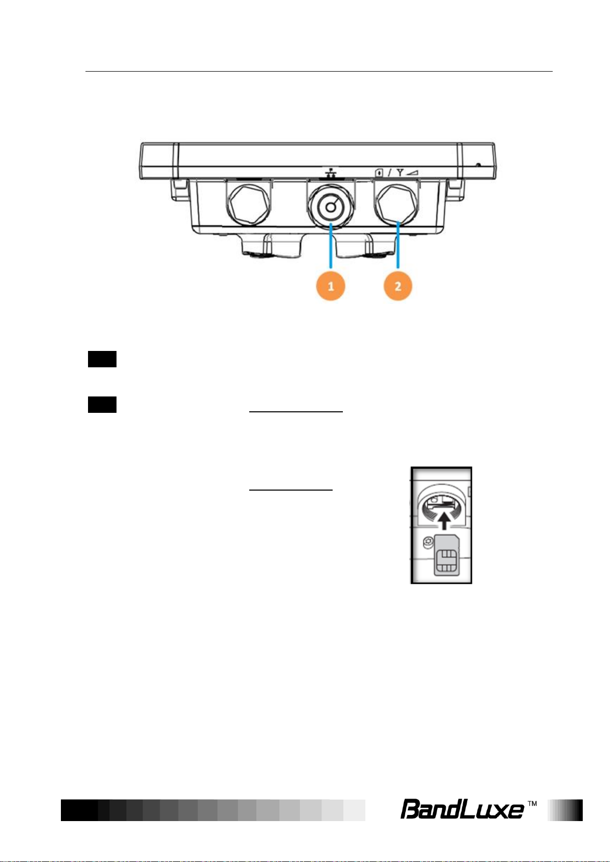
1
Ethernet (RJ-45)
port
Connect to the passive PoE adapter using an
Ethernet cable.
2
LED Indicators +
SIM card slot +
Reset button
LED Indicators:
The left LED indicates power status.
The right LED indicates the signal strength.
SIM card slot:
Insert the SIM card.
Reset button:
Short press to restart the device.
Long press for 10 seconds to reset the
settings to the factory default settings.
Hardware Overview
5
Page 8
Product Overview
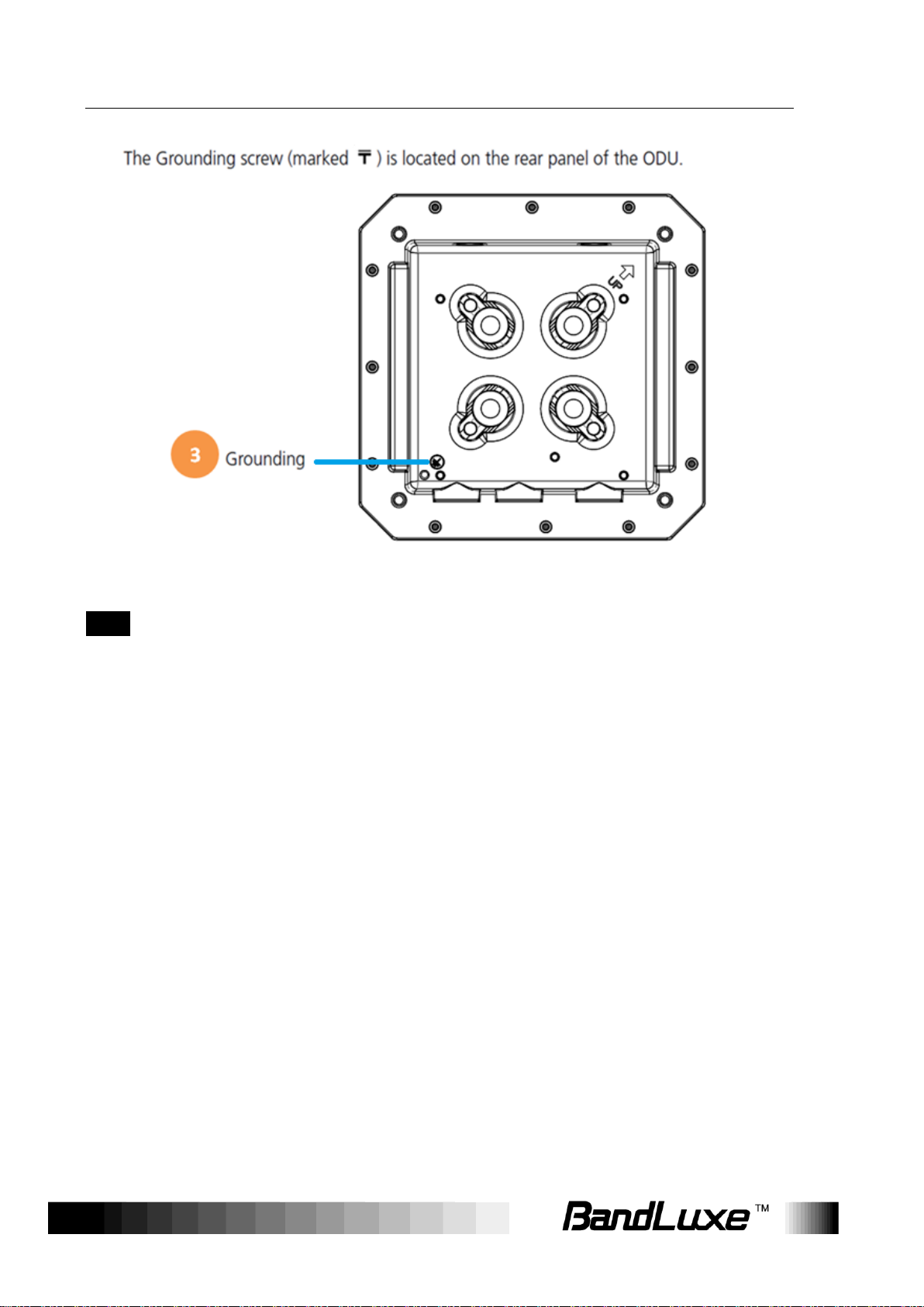
3
Grounding
Terminal
Connect a grounding cable to the terminal and a
ground connection.
NOTE 1
Use with Ethernet lightning protector between the
Ethernet cable and the PoE is suggested for better
lightning and surge protection.
NOTE 2
For additional lightning protection, use of a lightning
arrestor on the Ethernet cable near the area where the
Ethernet cable enters a building is suggested.
6
Page 9

Installation
Installation
Notice before installation
Install the SIM card
1. Unscrew the SIM card slot.
2. Insert a valid SIM card into the SIM card slot. Push it until it clicks in
place.
3. Screw the cap on tightly.
Choose a solid and safe pole for CPE installation
1. Choose the best location of the house and the orientation of the CPE
to get the strongest signal reception from base station.
2. The ambient temperature for E600 series must be within -40°C to
65°C (-40°F to 149°F).
NOTE
For lightning protection ground the CPE via Grounding Terminal and optimum
reception, there are a few things you should consider before installation. Please
see “Important Installation Considerations” on page 8 for more details.
Prepare two Ethernet cables
Be sure that one of the cables used is an outdoor grade CAT 5e (or above)
Ethernet cable type and the length of the cables are adequate to reach
the location of the CPE and indoor PPoE are.
Prepare wrenches
Prepare one wrench. The wrench size: 17mm x 1.
Warning:
Do NOT start any traffic test (ex: throughput test and Internet browsing)
before the installer returns to the ground.
7
Page 10

Installation
Important Installation Considerations
The LTE Advanced Outdoor CPE should be pole-mounted outdoors and
aligned so its antenna faces the nearest LTE eNB. Before installing the
outdoor CPE, consider the appropriate location, clearance, and device
orientation.
Location and Cable wiring
1. Consult your Service Provider to find the best location and angle for getting the
strongest signal from the base station.
2. Do a walking test around the house to find the best spot with the strongest signal
if you don’t obtain related information from Service Provider.
3. Mount the CPE at the highest possible location with a clear view of the base
station signal source. Buildings or other obstructions will affect the quality of the
signal you receive.
4. Keep the best distance as possible from other devices that may cause
interference.
5. Keep the LTE Advanced Outdoor CPE away from power lines.
6. Avoid placing LTE Advanced Outdoor CPE too close to any metallic reflective
surfaces.
7. Disconnect the power cord first before mounting the CPE. Otherwise this may
result in personal injury due to electric shock.
8. Be sure to ground LTE Advanced Outdoor CPE with an appropriate grounding
wire (not included) by attaching it to the grounding screw on the unit and to a
good ground connection.
8
Page 11

Installation
Mounting the Unit
Mount LTE Advanced Outdoor CPE on a 1”-4” pole using the supplied kit,
or the optional tilt accessory.
Using the clamp
1. Thread the M10*100mm bolts through spring washers, flat washers and bracket
holes.
2. With the connectors facing downwards, attach the LTE Advanced Outdoor CPE
to a 1” to 4” pole.
3. Attach the bracket to the other side of the pole.
4. Thread the M10*100mm bolts through the holes the bracket and into the LTE
Advanced Outdoor CPE.
Ground the CPE
For safe outdoor use, use the grounding terminal to ground the CPE
housing before making any connections.
You need the following:
Spring washer
M5x8 mm screw
NOTE
The spring washer and M4x8L screw are not included in your package.
9
Page 12
Installation
To ground the CPE:
1. Insert the washer to the M4x8L screw.
2. Attach the screw halfway into the earth ground terminal.
3. Insert the grounding cable under the washer.
4. Tighten the screw.
Making the Connections
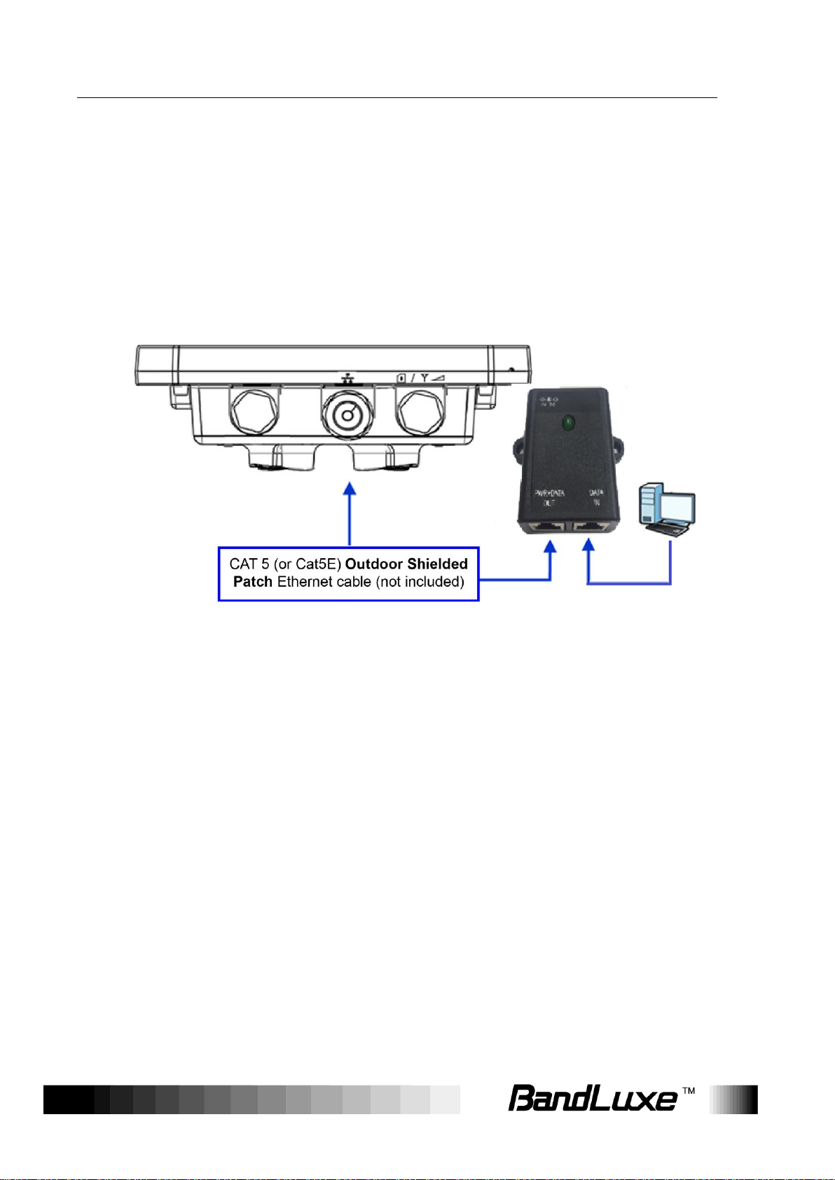
Connect the Ethernet Cable to the Unit
Use only 5E 4x2x24# FTP (or above) outdoor shielded patch cables from
an approved manufacturer.
1. Remove the sealing cable gland plug from the gland nut.
2. Open the sealing gland nut and remove it. Do not disassemble the
gland base from the bracket.
3. Insert the Cat5 RJ-45 cable into the sealing gland base and connect it
to the Ethernet port at the bottom of the unit. Make sure that the
connector is completely inserted and tightened.
NOTE
The total length of the Ethernet cable from the unit to the RJ-45 port on the PoE
must not exceed 80 meters.
4. Insert the rubber bushing on the cable into the gland base.
10
Page 13

Installation
5. Tighten the gland nut. Use the dedicated tool for fastening the sealing
glands.
Connect the Ethernet Cable to Computers
1. After connecting the Ethernet cable to the unit, install a protective
cover on the connector at the other end of the Ethernet cable.
2. Connect the Ethernet cable to the port on the PoE adapter labeled
PWR+DATA OUT.
3. Connect another Ethernet cable to the port on the PoE adapter
labeled DATA IN and the RJ-45 port on a PC/Notebook
PC/Hub/Swtch.
4. Connect the PoE adapter to a power source via the power
adapter/power cable.
11
Page 14
Using Web-based Management
Using Web-based Management
This chapter will guide you on how to configure your CPE via the
web-based utility.
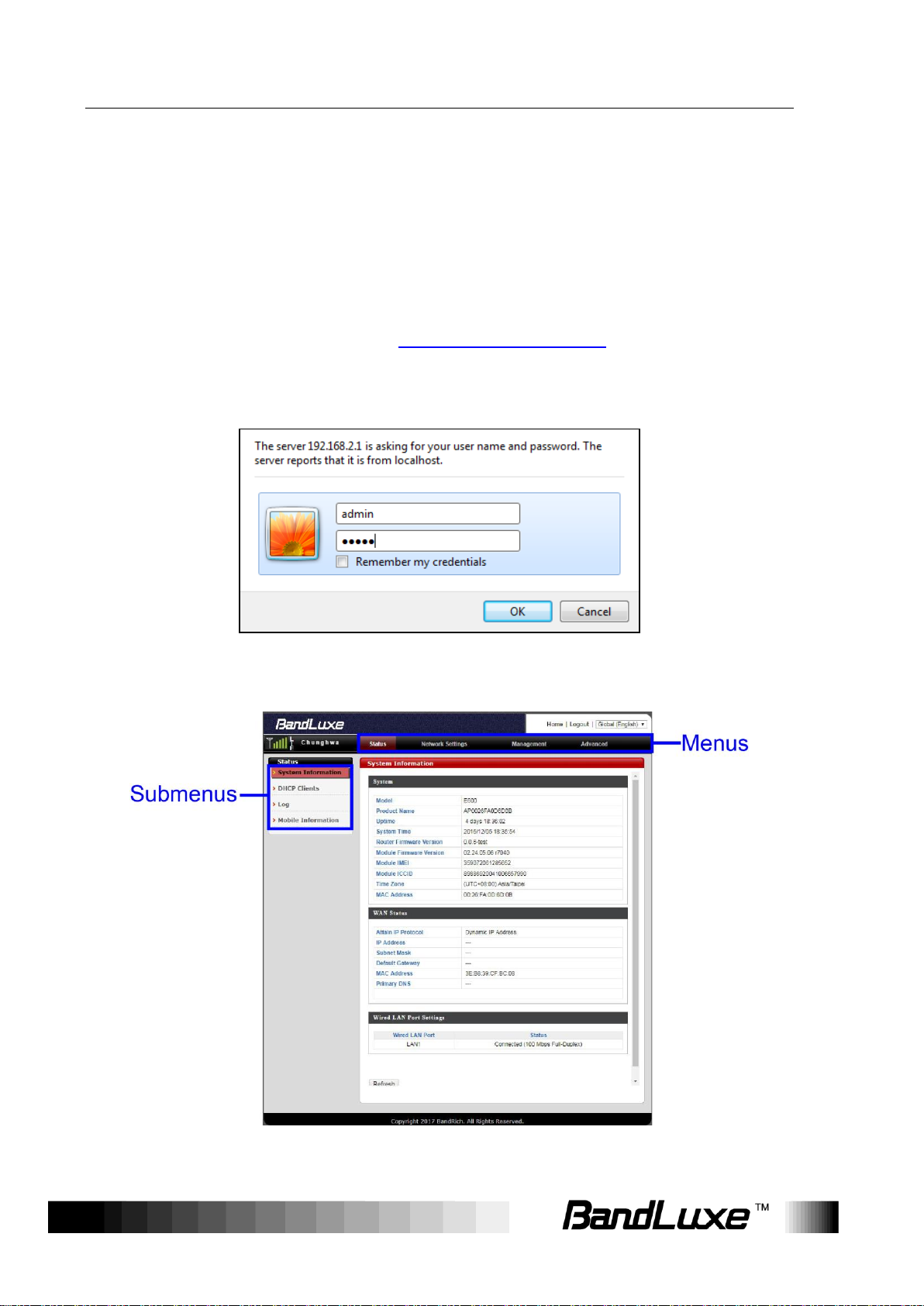
Login
1. Launch a web browser.
2. In the address bar, enter http://192.168.2.1, then press
Enter.
3. In the login window, enter the username “admin” and
password “admin”.
4. Click OK to login to the main screen.
5. Click one of the menus or submenus to configure the system.
12
Page 15

Using Web-based Management
The E600 Series CPE uses the network domain 192.168.2.X, for any
downstream connections, all devices should avoid using this network
domain otherwise there might be conflicting IP addresses which will
cause communication failure.
If you cannot connect to the network, please follow the steps below to
set the APN manually:
1. Go to Network Settings > WWAN Setting > APN Profile Settings to
enter the APN profile name, and then click Add.
2. Enter the APN, User Name, and Password, and then click Save.
3. Go to Network Settings > WWAN Setting > Network Settings and
change the APN field to Manual, then select the profile name you added
and click Apply. The changes will be applied after the system is
rebooted.
If PIN verification on you SIM card is enabled, go to Network Settings
> Mobile Settings > UICC/SIM PIN Management to unlock the PIN
code.
If a SIM card is reinserted you must restart the CPE to read the SIM
card properly.
For more detailed information please go to
http://www.bandrich.com/UM/E600_ Series.pdf to download the user
manual.
13
Page 16
Using Web-based Management
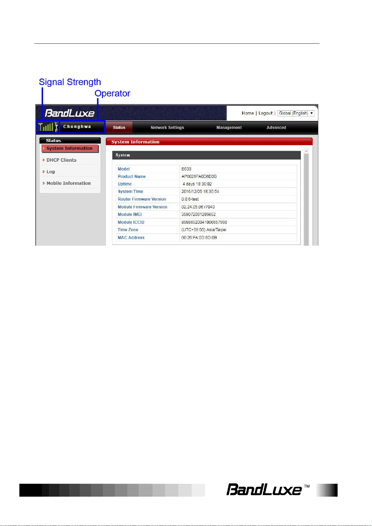
Signal Strength:
Displays signal type and signal strength.
If the mobile Internet connection is not
established, No Service will appear.
If the mobile Internet connection is established,
3G or LTE will appear based on its
corresponding signal type.
Operator:
Displays the name of Internet service provider.
Signal Strength & Operator
On the top-left corner of the web-based management interface, the signal
and operator indicator next to the menu bar demonstrates the signal
strength and name of Internet service provider.
14
Page 17
Using Web-based Management
Status
The Status menu displays status information for the router. The
associated submenus are: System Information, DHCP Clients, Log,
and Mobile Information.
15
Page 18
Using Web-based Management
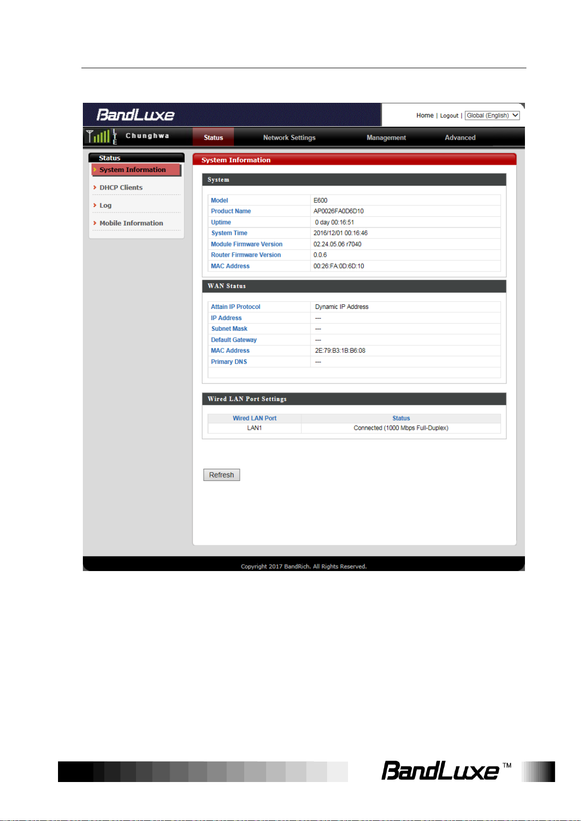
System Information
The System Information submenu displays general information about
the router.
Click Refresh at the bottom of this menu to update the system
information.
16
Page 19
Using Web-based Management
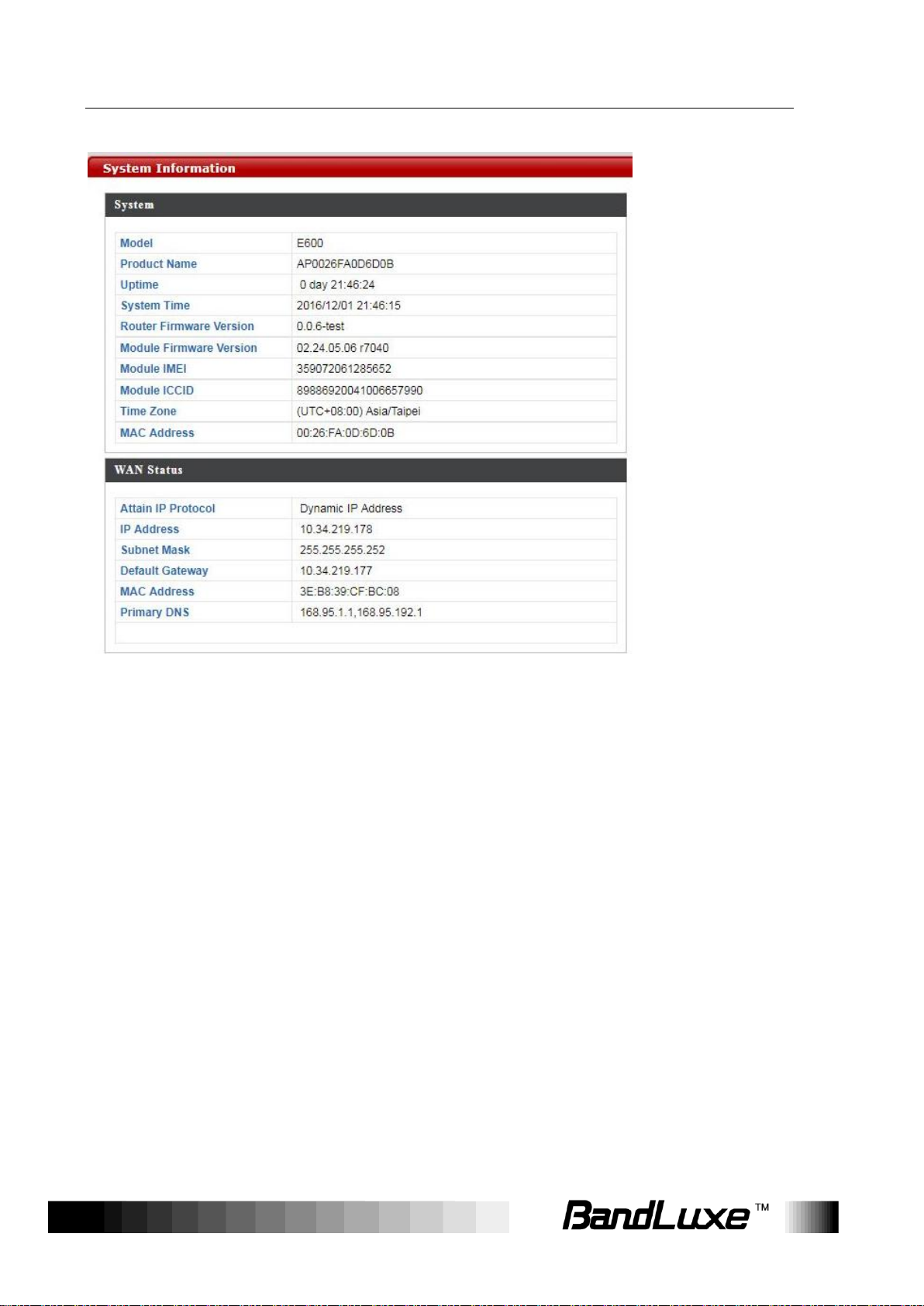
System
This section displays system information: model, product name, uptime,
system time, router firmware version ,module firmware version, module
IMEI, module ICCID, time zone, and mac address.
Click Refresh to refresh the IP address.
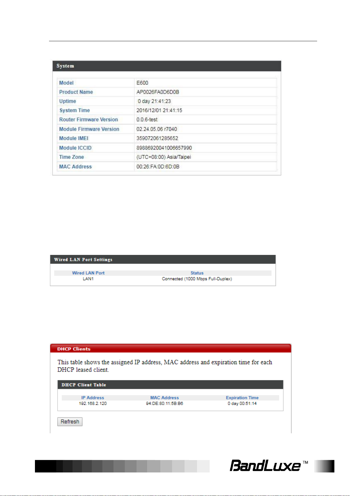
Wired LAN Port Settings
This section displays the wired LAN port and its connection status.
DHCP Clients
17
Page 20

Using Web-based Management
The DHCP Clients submenu displays DHCP lease information for each
client, including IP address, MAC address, and lease time remaining.
Click Refresh to update the DHCP lease information.
18
Page 21
Using Web-based Management
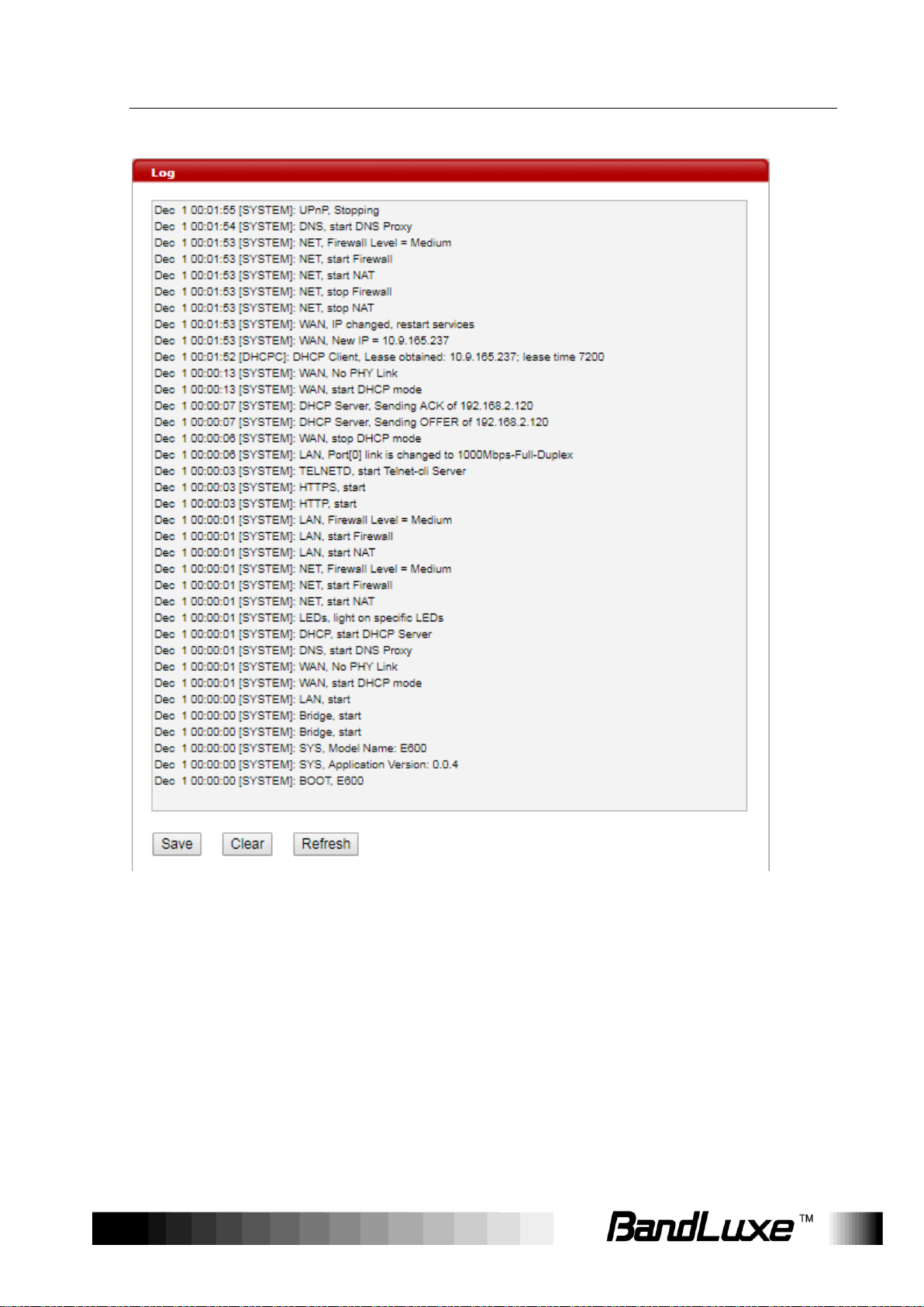
Log
The Log submenu tracks system activities after the system is powered
on.
Click Save to save the record of system activities.
Click Clear to clear the record of system activities.
Click Refresh to update the record of system activities.
19
Page 22
Using Web-based Management
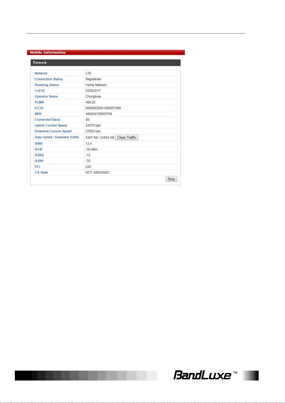
Mobile Information
The Mobile Information submenu displays detailed network statuses for
the router, including network, connection status, roaming status, cell ID,
operator name, PLMN, ICCID, IMSI, connected band, uplink current
speed, downlink current speed, data uplink and downlink traffic, SINR,
RSSI, RSRQ, RSRP, PCI, and CA state.
Click Clear Traffic to clear the data uplink and downlink traffic.
20
Page 23

Using Web-based Management
Network Settings
The Network Settings menu features detailed network settings and
configurations for the router. The associated submenus are: LAN-side IP
Address, LAN Port, WAN > WAN Settings, WAN > WAN Status,
Firewall > Enable, Firewall > DMZ, Firewall > Dos, Firewall > Access
Control, Firewall > URL Filter, Firewall > Security Filter, Advanced
Settings > Enable, Advanced Settings > Port Forwarding, Advanced
21
Page 24

Using Web-based Management
IP Address Assignment:
Select Dynamic IP Address or Static IP Address
Settings > Virtual Server, Advanced Settings > Special Application,
Advanced Settings > ALG, Advanced Settings > UPnP, Advanced
Settings > Dynamic DNS, Advanced Settings > Remote Access,
Mobile Internet > WWAN Setting, Mobile Internet > UICC/SIM PIN
Management, Mobile Internet > SIM Management, Mobile Internet >
Preferred Network, and Mobile Internet > AT Command.
LAN-side IP Address
The LAN-side IP Address submenu allows users to change LAN-side IP
address and DHCP server configurations.
Click Apply to have any changes to the configurations take effect.
LAN-side IP Address
22
Page 25

Using Web-based Management
by clicking the drop-down list.
IP Address:
Allows users to manually configure the IP
address if Static IP Address is selected.
Subnet Mask:
Allows users to manually configure subnet
mask if Static IP Address is selected.
DHCP Server:
Click the drop-down list to enable or disable the
DHCP server feature.
Starting IP Address:
Specifies the starting number of assigned client
IP address.
Ending IP Address:
Specifies the ending number of assigned client
IP address.
Domain Name:
Specifies the Domain Name.
Lease Time:
Specifies the amount of lease time allocated to
clients of this router, i.e. the expiry time of
leased addresses. Click the drop-down list to
set lease time.
Primary DNS:
Allows users to specify the primary Domain
Name System if necessary.
Secondary DNS:
Allows users to specify the secondary Domain
Name System if necessary.
DHCP Server
23
Page 26

Using Web-based Management
Wired LAN Port:
Displays the wired LAN port.
Speed & Duplex:
Allows users to select router speed and data
transmission method. The available options
are: Auto, 10 Mbps Half-Duplex, 10 Mbps
Full-Duplex, 100 Mbps Half-Duplex, 100 Mbps
Full-Duplex, and 1000 Mbps Full-Duplex.
Flow Control:
Allows users to enable or disable Ethernet flow
control.
802.3az
Allows users to enable or disable IEEE 802.3az
energy-efficient technology.
LAN Port
The LAN Port submenu allows users to change Wired LAN Port
Settings.
Click Apply to have any changes to the configurations take effect.
WAN Settings
Select a Wide Area Network (WAN) connection mode
and configure the settings. If you are unsure about your
connection type, contact your ISP.
24
Page 27

Using Web-based Management
Host Name
Enter the host name of your computer.
MAC Address
For some applications, you may need to
designate a specific MAC address for the router.
Please enter the MAC address here. If you are
connecting the router to a computer, press “Clone
Mac” to automatically enter
your computer’s MAC address.
MTU
Enter the maximum transmission unit (MTU)
value of your network connection. The default
value is 1500.
IP Address
Input the IP address assigned by your ISP
here.
Subnet Mask
Input the subnet mask assigned by your ISP
here.
Default Gateway
Address
Input the default gateway assigned by your
ISP here. Some ISPs may call this “Default
Route”.
DNS Address 1 & 2
Enter the DNS address(es) assigned by your
ISP here.
MTU
Enter the maximum transmission unit (MTU)
value of your network connection. The
default value is 1500.
Dynamic IP
Select “Dynamic IP”. If your Internet service provider
assigns IP address automatically using DHCP (Dynamic
Host Configuration Protocol).
Static IP
Select “Static IP” if your ISP provides Internet access via a fixed IP
address. Your ISP will provide you with such information as IP address,
subnet mask, gateway address, and DNS address.
25
Page 28

Using Web-based Management
Firewall Module
Function
Check Enable or Disable to enable or disable
this feature.
WAN Status
The WAN Status submenu displays current configurations for the WAN.
The associated items are: Attain IP Protocol, IP Address, Subnet Mask,
Default Gateway, MAC Address, and Primary DNS.
Enable
The Enable submenu allows users to activate or deactivate the Firewall
Module function.
Click Apply to have any changes to the configurations take effect.
26
Page 29

Using Web-based Management
DMZ: Allows users to enable or disable DMZ.
DMZ
The DMZ submenu allows users to enable and configure a DMZ for their
router.
When a firewall is used, it is sometimes necessary to place some clients
(for example, for Internet games, video conferencing, or VPN connections)
outside of the firewall while leaving the others protected. Users are
allowed to do this using a Demilitarized Zone (DMZ). This DMZ feature
allows users to specify the IP address of the computers that are placed
outside the firewall of the network.
Enable DMZ
27
Page 30

Using Web-based Management
Enable DMZ
Check/uncheck the box to enable/disable the
device’s DMZ function.
Add DMZ
Select “Dynamic IP” or “Static IP” here.
For “Dynamic IP” select an Internet connection
session from dropdown menu.
For “Static IP” enter the IP address that you want to
map to a specific private IP address.
Client PC
Enter the private IP address that the internet IP
address will be mapped to.
Add
Click “Add” to add the client to the “Current
DMZ Table”.
Add DMZ
A Demilitarized Zone (DMZ) is an isolated area in your local
network where private IP addresses are mapped to specified
Internet IP addresses, allowing unrestricted access to the
private IP addresses but not to the wider local network.
You can define a virtual DMZ host here. This is useful for
example, if a network client PC cannot run an application
properly from behind an NAT firewall, since it opens the client
up to unrestricted two-way access.
DMZ Table
This section allows users to manage the DMZ host list.
To remove specific DMZ hosts, select those DMZ hosts and click Delete
Selected. To remove all DMZ hosts, click Delete All.
28
Page 31

Using Web-based Management
Ping of Death
Specify the frequency of ping of death packets
which will trigger the router’s DoS protection function.
Port Scan
Intruders use “port scanners” to detect open
Internet IP address ports. Check each type of port
scan to prevent.
Sync Flood
Specify the frequency of sync flood packets which
will trigger the DoS protection function.
Dos
Denial-of-Service (DoS) is a common form of malicious
attack against a network. The router’s firewall can protect
against such attacks.
If you are not familiar with these functions, it is recommended
you keep the default settings.
Advanced Denial of Service Features
29
Page 32

Using Web-based Management
Access Control
The Access Control submenu allows users to filter access for the
network.
30
Page 33

Using Web-based Management
MAC Filter:
Check or uncheck to enable or disable this
feature.
Action:
Check Deny or Allow to deny or allow
connections from MAC addresses specified in
the MAC Filter Table if MAC Filter is enabled.
Client PC MAC
Address:
Enter the MAC address of a computer to be
denied or allowed access in the field.
Comment:
Provide a description of the filtered connection.
Enable/Disable MAC Filter
This section allows users to filter wireless connections by MAC address.
Add MAC Filter
If a MAC filter is enabled, follow the instructions below for each field.
Click Add to add the MAC address filtering entry or Reset to redo.
MAC Filter Table
This section allows users to manage MAC address filtering entries. All
MAC address filtering entries you have created will be displayed in this
table.
31
Page 34

Using Web-based Management
IP Filter:
Check or uncheck to enable or disable this
feature.
Action:
Check Deny or Allow to deny or allow
connections from IP addresses specified in the
IP Filter Table if IP Filter is enabled.
To remove specific MAC filtering entries, select those entries and click
Delete Selected. To remove all MAC filtering entries, click Delete All.
Enable IP Filtering Table
This section allows users to filter wireless connections by IP address.
IP Filter Table
This section allows users to manage IP filtering entries.
To remove specific IP addresses, select those IP addresses and click
Delete Selected. To remove all IP addresses, click Delete All.
To add new IP filtering entries, click Add and menu appears allowing the
user to define the IP address that will be filtered. In the menu, follow the
instructions below for each field.
32
Page 35

Using Web-based Management
Client PC Description:
Provide a description of client computer.
Client PC IP Address:
Enter an IP address range for the computers to
be denied or allowed access.
Client Service:
Check or uncheck to authorize or un-authorize
client computer to use specific services through
the network.
Protocol:
Click the drop-down list to select a protocol.
The available options are: Both, TCP, and
UDP.
Port Range:
Enter the port range for the computers to be
denied or allowed access.
Click Add to add a new IP filtering entry or Reset to redo configurations.
33
Page 36

Using Web-based Management
Proxy:
Use of WAN proxy servers may compromise
the Router's security. Check this option to
disable access to any WAN proxy servers.
URL Filter
The “Firewall” menu provides access to URL blocking functions to
improve the security of your wireless network.
Security Filter
The Security Filter submenu allows users to use the Web Filter feature.
This feature allows users to enable up to four specific filtering methods.
34
Page 37

Using Web-based Management
Java:
Java is a programming language for websites.
Check this option to disable Java. If Java is
disabled, users run the risk of not having
access to Internet sites created using this
programming language.
ActiveX:
ActiveX is a programming language for
websites. Check this option to disable ActiveX.
If ActiveX is disabled, users run the risk of not
having access to Internet sites created using
this programming language.
Cookie:
A cookie is data stored on the PC and used by
Internet sites when users interact with them.
Check this option to disable cookies.
Enable
Enable or disable NAT (Network Address Translation) for better network
performance
35
Page 38

Using Web-based Management
Port Forwarding:
Allows users to enable or disable service
provided on their network for external devices
to access, such as web servers, ftp servers,
e-mail servers, and other specialized Internet
applications. Check or uncheck to enable or
Port Forwarding
The Port Forwarding submenu allows users to set port forwarding
configurations.
Port Forwarding allows you to set up public services on your network,
such as web servers, ftp servers, e-mail servers, and other specialized
applications.
Enable Port Forwarding
36
Page 39

Using Web-based Management
disable this feature.
Local IP:
Enter the IP address of the computer running
specific applications.
Type:
Check the drop-down list to select a service
type. The available options are: Both, TCP, and
UDP.
Port Range:
Enter the start port number and the end port
number to specify the range for port forwarding.
Comment:
Provide a description of the rule.
Add Port Rule
If the port forwarding function is enabled, follow the instructions below for
each field.
Click Add to add a rule or Reset to reset.
Port Forwarding Table
This section allows users to manage port forwarding rules. All port
forwarding rules you have created will be displayed in this table.
To remove specific rules, select those rules and click Delete Selected. To
remove all rules, click Delete All.
37
Page 40

Using Web-based Management
Local IP
Specify the IP address of the computer on
your local network.
Local Port
Specify the private port you wish to use on
the computer in your local network.
Type
Select the type of Internet Protocol.
Public Port
Specify a public port to access the computer
on your local network.
Comment
Enter a comment for reference or identification.
Visual Server
This function allows you to set up an internet service on a
local computer, without exposing the local computer to the
internet. You can also build various sets of port redirection, to
provide various internet services on different local computers
via a single internet IP address.
38
Page 41

Using Web-based Management
Delete Selected/
Delete All
Delete selected or all entries from the table.
Visual Server Table
Current Virtual Table entries will be displayed in the table shown below
Special Application
The Special Application submenu allows users to use the port triggering
feature. Port Triggering allows the router to watch outgoing data for
specific port numbers. The router remembers the IP address of the
39
Page 42

Using Web-based Management
Trigger Port:
Allows users to monitor outgoing data for
specific port numbers. Check or uncheck to
enable or disable this feature.
Popular Applications:
Click the drop-down list and select an
application, then click Add next to the
drop-down list. After clicking Add, all fields
relating to this application will be automatically
filled. Make sure that all options and
parameters in the fields are applicable. If
necessary, you are allowed to configure
manually. Then click Add at the bottom to add
this application as a port triggering entry.
Trigger Port:
Enter the start port number and the end port
number manually for a selected application if
necessary.
computer that sends the matching data, so that when the requested data
returns through the router, the data is pulled back to the proper computer
by way of IP address and port mapping rules.
Enable Trigger Port
Add Trigger Port
If the port triggering function is enabled, follow the instructions below for
each field.
40
Page 43

Using Web-based Management
Trigger Type:
Click the drop-down list and select the protocol
used for the specific application. The available
options are: Both, TCP, and UDP.
Public Port:
Enter the port number manually for a selected
application if necessary.
Public Type:
Click the drop-down list and select the protocol
used for the specific application. The available
options are: Both, TCP, and UDP.
Comment:
Provide a description of an entry.
Click Add at the bottom to add a new Trigger Port rule or Reset to reset.
Trigger Port Table
This section allows users to manage Trigger Port rules.
To remove specific rules, select those rules and click Delete Selected. To
remove all rules, click Delete All.
41
Page 44

Using Web-based Management
UPnP:
Check Enable or Disable to enable or disable
UPnP.
ALG
Enable or disable ALG(Application Layer Gateway)
UPnP
The UPnP submenu allows users to enable or disable UPnP (Universal
Plug and Play) which allows wired and wireless network devices to
identify each other and establish network services.
Click Apply to have any changes to the configurations take effect or
Cancel to abort.
42
Page 45

Using Web-based Management
Enable:
Allows users to enable or disable Dynamic
DNS.
If Dynamic DNS is enabled, follow the instructions below for each field.
Service:
Specify the Dynamic DNS service URL. Click
the drop-down list and select a URL from the
list.
Hostname:
Enter the hostname for a Dynamic DNS
account.
Username:
Enter the username for a Dynamic DNS
account.
Password:
Enter the password for a Dynamic DNS
account.
Dynamic DNS
The Dynamic DNS submenu features configuration options for Dynamic
DNS (Dynamic Domain Name Service), which is a system that allows the
domain name data held in a name server to be updated in real time. It
allows an Internet domain name to be assigned to a computer with a
varying (dynamic) IP address. For using this feature, users need to sign
up for DDNS with a DDNS provider, refer to www.dyndns.org or
www.TZO.com.
Click Apply to have any changes to the configurations take effect.
43
Page 46

Using Web-based Management
Remote Access:
Allows users to enable or disable this feature.
If a remote access is enabled, follow the instructions below for each field.
Remote Access Port:
Enter the port number for the remote access.
The default setting is Port 80.
Remote Access
The Remote Access submenu allows users to specify whether or not to
allow remote access for this router.
Click Apply to have any changes to the configurations take effect.
44
Page 47

Using Web-based Management
WWAN Setting
The WWAN Setting submenu allows users to change WWAN network
settings.
Click Apply at the bottom of this submenu to have any changes to the
configurations take effect.
Network Setting
45
Page 48

Using Web-based Management
Roaming Connection:
Allows users to enable or disable this feature.
If a roaming connection is enabled, follow the instructions below for each
field.
APN:
Check Auto to use automatic APN (Access
Point Name) profile settings or Manual for the
manual choice of APN profile settings for the
network.
Profile Selection:
Select the APN profile you have created. Profile
Selection does not appear if APN is set to Auto.
IP Protocol:
Select an IP protocol. The available options
are: IPV4, IPV6, and IPV4V6.
APN:
Displays current APN information.
APN Information
46
Page 49

Using Web-based Management
APN Profile Settings:
Allows users to establish a new APN profile.
Enter a new APN profile name in the field and
click Add to add a new APN profile. All APN
files you have created will be displayed in APN
Profile Table.
APN Profile Settings
APN Profile Table
This section allows users to manage APN profile settings.
To remove specific APN profiles, select those profiles and click Delete
Selected. To remove all profiles, click Delete All.
To edit an APN profile, click Edit.
47
Page 50

Using Web-based Management
USIM Status:
Displays current SIM card status of the router.
“READY” means that the SIM card is enabled
for mobile Internet access.
PIN Remain:
Displays how many attempts remain for
entering the correct PIN code.
PIN Protection:
Check Enable or Disable to enable or disable
the PIN code protection.
UICC/SIM PIN Management
The UICC/SIM PIN Management submenu allows users to manage the
SIM card.
USIM Status
USIM’s PIN Management
48
Page 51

Using Web-based Management
If a PIN protection is enabled, follow the instructions below for each field.
PIN Code:
Set a PIN code if users do not want the SIM
card to be used without permission. Once PIN
protection is enabled, every time users start the
router with the specific SIM card inserted, users
need to the enter the PIN code.
SIM Lock Status:
“There is no SIM lock” means the SIM card is
unlocked.
If the SIM card is locked for some reason, the
SIM Unlock field will appear in the image
allowing users to enter the SIM unlock code to
unlock it. After entering the SIM unlock code in
the field, click Apply.
Click Apply to have any changes to the configurations take effect.
SIM Management
The SIM Management submenu displays the current SIM lock status.
Preferred Network
49
Page 52

Using Web-based Management
Network Type:
Displays the current network type. Click the
drop-down list to select the preferred mobile
network type. The default option is Auto. Other
available options are LTE (4G), WCDMA (3G)
and GSM.
The Preferred Network submenu allows users to select the network
type.
AT Command
The AT Command submenu displays AT command sets.
50
Page 53

Using Web-based Management
Management
The Management menu displays several features to manage the router.
The associated submenus are: Admin, Date and Time, and Syslog
Server.
51
Page 54

Using Web-based Management
Administrator Name:
Allows users to configure the administrator
account name for the router by entering an
account name for an administrator account.
Administrator
Password:
Allows users to configure a password for an
administrator account. Enter the password
again to confirm the password.
Admin
The Admin submenu allows users to configure administrator settings.
Account to Manage This Device
Click Apply to have any changes to the configurations take effect.
52
Page 55

Using Web-based Management
Advanced Settings
Input the Product Name and Enable or disable Mangement Portocol
Date and Time
The Date and Time submenu allows users to configure the date and time
settings.
53
Page 56

Using Web-based Management
Local Time:
Displays current local time. It allows users to
set the date and time manually by clicking the
drop-down lists or clicking Acquire Current
Time from Your PC to fill the fields
automatically using the date and time of their
computers.
Use NTP:
Check or uncheck to enable or disable NTP
(Network Time Protocol) client.
If a NTP is enabled, follow the instructions below for each field.
Server Name:
Select the preferred NTP server from the
drop-down list or enter the desired server
candidates in the field after enabling the Use
NTP function.
Update Interval:
Set update frequency. The field is greyed out if
Use NTP is not enabled.
Date and Time Settings
NTP Time Server
Time Zone
54
Page 57

Using Web-based Management
Time Zone:
Click the drop-down list and select the desired
time zone.
Syslog Server
Enable or disable Syslog Server.
55
Page 58

Using Web-based Management
Advanced
The Advanced menu displays Update Firmware, Save/Restore
Settings, Factory Default, Reboot, and Help.
56
Page 59

Using Web-based Management
Update Firmware
The Update Firmware submenu allows users to update the firmware for
the router.
Firmware Location
This section allows users to choose where the firmware update file is
located.
Update Firmware from PC
This section allows users to update the router with the latest firmware.
Click Choose File to browse and select the firmware package file, and
then click Update. Once the firmware has been updated successfully, the
router will restart.
57
Page 60

Using Web-based Management
Warning: Updating firmware may take a few minutes. Do NOT
turn off the power or press the Reset button during the update
process.
Save/Restore Settings
The Save/Restore Settings submenu allows users to save and restore
the current router settings.
Save/Restore Method
This section allows users to choose where the router’s settings will be
saved or restored from.
58
Page 61

Using Web-based Management
Save Settings to PC
Users can save all current settings of the router to a TAR archive file on
their computers.
Router settings can be protected by a password. Check Encrypt the
configuration file with a password, enter a password in the field then
click Save to save the router settings. Once the encryption is enabled,
every time users want to restore the specific settings, users need to enter
the password.
If protection is not needed, just click Save to save the settings.
Restore Settings from PC
Users can restore router settings previously saved as a TAR archive file
on their computers.
Click Choose File to find and select the desired TAR archive file and click
Restore. The system will restart after the restoration process has been
finished. If a TAR archive file is encrypted, users need to enter the
password before the settings can be restored.
59
Page 62

Using Web-based Management
Factory Default
Click Factory Default to restore the router to its original factory settings.
When clicking Factory Default, a dialog box will appear to indicate the
reset process. Follow the instructions to restart and return the router to its
initial settings.
Reboot
Click Reboot to restart the router.
Help
Click Download to download the latest Quick Start Guide or User Manual
of this router.
60
Page 63

Appendix A: FAQ
Appendix A: FAQ
Appendix A contains a list of frequently asked questions when you set up
your CPE configuration.
Q: What is an IP address and how do I find my computer IP
address?
A: IP address is the identifier for a computer or device on a
TCP/IP network. Networks using the TCP/IP protocol route
messages based on the IP address of the destination. The
format of an IP address is a 32-bit numeric address written as
four numbers separated by periods. Each number can be zero
to 255.
For example, 192.168.168.254 could be an IP address.
To find your computer IP address,
In Windows, click Start > Run to launch the Command
program.
Type “ipconfig”, then press the Enter button.
Your computer IP address is listed on the IP Address.
Q: What is Long Term Evolution (LTE)?
A: LTE is a 4th generation (4G) mobile broadband standard and is
the successor to the 3G technologies CDMA/GSM/UMTS. The
service is typically much faster on both uplink/download
speeds.
Q: What is a firewall?
A: A firewall is a set of related programs that protects the
resources of a private network from users from other
networks.
Q: What is Network Address Translation (NAT)?
61
Page 64

Appendix A: FAQ
A: Network Address Translation (NAT) is the process where a
network device, usually a firewall, assigns a public address to a
computer (or group of computers) inside a private network.
Q: What is Universal Plug and Play (UPnP)?
A: UPnP is an open networking architecture that consists of
services, devices, and control points. The ultimate goal is to
allow data communication among all UPnP devices regardless
of media, operating system, programming language, and
wired/wireless connection.
62
Page 65

Appendix B: Specifications
Physical
Cellular Modem
Embedded, 3GPP Rel 10, LTE Advance FDD&TDD
Dimensions
247 (L) x 247 (W) x 107 (H) mm
Weight
1.5kg
Water Resistant IP
Code
IP66
Interface
Ethernet Port
RJ45 x 1, with power riding on Ethernet cable
SIM Card
1 x SIM slot for external 2FF SIM plug-in with sealing
protection
Reset Button
Reset to factory default setting
LED Indicator
Signal strength indicator x 2
Signal indicator x 1
Power indicator x 1
Connectivity and Data Speed
LTE Band
B1, B2, B3, B4, B5, B7, B12, B13, B20, B25, B26, B29, B30,
B41
LTE Bandwidth
Up to 40 MHz (2 CA)
LTE Data Rate
FDD: Downlink up to 300 Mbps, Uplink up to 50 Mbps
TDD: Downlink up 222 Mbps, Uplink up to 26 Mbps
WCDMA Band
B1, B2, B3, B4, B5, B8
WCDMA Rate
Downlink: 42 Mbps
Uplink: 5 Mbps
Antenna
Antenna Type
Embedded tri-band directional antenna
Antenna Gain
Refer to Appendix C.
Appendix B: Specifications
NOTE: Specifications are subject to change without notice.
63
Page 66

Appendix B: Specifications
Cellular Main
Antenna
Yes
Cellular Diversity
Antenna
Yes
LTE MIMO
Downlink 2x2
Router Features
Security
Multiple VPN pass-through (IPSec, PPTP, L2TP), Stateless
and SPI Firewall, Internet Filter, Web Filter
NAT-NAPT
Single Port Forwarding, Port Range Forwarding, Port Range
Triggering, Port Filtering, IP Filtering, DMZ, UPnP, Multicast
Pass-Through
DNS
DNS Agent, DDNS
Other Features
IPv4 and IPv6, TCP, UDP, ICMP, ARP, DHCP Server/Client,
DHCP Reservation, HTTP/HTTPs, NTP, ALGs
Software Features
CPE Operation Mode
Router mode
Connection Status in
Web GUI
Network name, Signal strength, Roaming indication, Radio
technology, Radio network parameters, Connection status,
Connection time, Connection Statistics
Connection
Management
Connection on demand, Auto Connection, Auto APN
matching with USIM, APN database update through
browser-based GUI, APN profile, PIN management,
Preferred radio network type selection
Support FW Version
Upgrade
Yes
Device Management
TR-069, SNMP, Remote GUI Log-in
System Protection
Two types of user account: User and Operator
Every user account has separate password protection
mechanism
Browser-based
Administration GUI
Browser supported: IE, Firefox, Safari, Chrome
Browser-based
Administration GUI
Multi-Language
Support
English
64
Page 67

Appendix B: Specifications
Power Input
Passive Power over
Ethernet (PPoE)
48V Passive PoE input power
Accessories
Passive Power over
Ethernet Adapter
RJ-45 x 2 (Data In x 1, Data & Power Out x 1)
48V/1A
Mounting Bracket
Fixture (match to the back design) and screws (for mounting
on pole and wall)
Left-right rotatable
30-meter Ethernet
Cable (Optional)
Outdoor grade Ethernet cable with water-proof RJ-45 head at
one end
15-meter Ethernet
Cable (Optional)
Outdoor grade Ethernet cable with water-proof RJ-45 head at
one end
Environment
Operation
Temperature
(Excluding Power
Adaptor)
-40oC to 65oC (-40oF to 149oF)
Power Adaptor
Operation
Temperature
0oC to 40oC (32oF to 104oF)
Storage Temperature
-40oC to 70oC (-40oF to 158oF)
Operating Humidity
5% to 90% Non-Condensing
Storage Humidity
5% to 95% Non-Condensing
Certification and Conformance
65
Page 68

Appendix C: Important Safety Information and Glossary
Appendix C: Important Safety
Information and Glossary
Europe – EU Declaration of Conformity
European Union Notice
Products with CE marking comply with the R&TTE Directive (99/5/EC), the EMC
Directive (2004/108/EC), and the Low Voltage Directive (2006/95/EC) issued by the
Commission of the European Community.
Compliance with these directives implies conformity to the following European
Norms (in parentheses are the equivalent international standards).
EN 60950-1 (IEC 60950-1)
Safety of Information Technology Equipment.
EN 300 328
Electromagnetic compatibility and Radio spectrum Matters (ERM); Wideband
Transmission systems; data transmission equipment operating in the 2.4 GHz
ISM band and using spread spectrum modulation techniques.
EN 301 489-24
Electromagnetic compatibility and Radio spectrum Matters (ERM);
Electromagnetic Compatibility (EMC) standard for radio equipment and services;
66
Page 69

Appendix C: Important Safety Information and Glossary
Part 24: Specific conditions for IMT-2000 CDMA direct spread (UTRA) for mobile and
portable (UE) radio and ancillary equipment.
ETSI EN 301 511
Global system for mobile communications (GSM); Harmonised EN for mobile stations
in the GSM 900 and GSM 1800 bands, covering essential requirements of article 3.2
of the R&TTE directive (1995/5/EC).
ETSI EN 301 489-1
Electromagnetic compatibility and Radio spectrum Matters (ERM);
Electromagnetic Compatibility (EMC) standard for radio equipment and
services; Part 1: Common technical requirements.
ETSI EN 301 489-7
Electromagnetic compatibility and Radio spectrum Matters (ERM);
Electromagnetic Compatibility (EMC) standard for radio equipment and services;
Part 7: Specific conditions for mobile and portable radio and ancillary equipment of
digital cellular radio telecommunications systems (GSM and DCS).
ETSI EN 301 489-17
Electromagnetic compatibility and Radio spectrum Matters (ERM);
Electromagnetic Compatibility (EMC) standard for radio equipment and services;
Part 17: Specific conditions for 2.4 GHz wideband transmission systems.
ETSI EN 301 908-1 & -2
Electromagnetic compatibility and Radio spectrum Matters (ERM); Base Stations (BS),
Repeaters and User Equipment (UE) for IMT-2000 Third Generation cellular networks;
Part 1: Harmonised EN for IMT-2000, introduction and common requirements,
covering essential requirements of article 3.2 of the R&TTE Directive.
67
Page 70

Appendix C: Important Safety Information and Glossary
EN 50385
Product standard to demonstrate the compliance of radio base stations and fixed
terminal stations for wireless telecommunication systems with the basic restrictions or
the reference levels related to human exposure to radio frequency electromagnetic
fields (110 MHz - 40 GHz) - General public.
Federal Communication Commission
Interference Statement
15.21
You are cautioned that changes or modifications not expressly approved by the part
responsible for compliance could void the user’s authority to operate the equipment.
15.105(b)
Federal Communications Commission (FCC) Statement
This equipment has been tested and found to comply with the limits for a Class B
digital device, pursuant to part 15 of the FCC rules. These limits are designed to
provide reasonable protection against harmful interference in a residential installation.
This equipment generates, uses and can radiate radio frequency energy and, if not
installed and used in accordance with the instructions, may cause harmful
interference to radio communications. However, there is no guarantee that
interference will not occur in a particular installation. If this equipment does cause
harmful interference to radio or television reception, which can be determined by
turning the equipment off and on, the user is encouraged to try to correct the
interference by one or more of the following measures:
- Reorient or relocate the receiving antenna.
- Increase the separation between the equipment and receiver.
- Connect the equipment into an outlet on a circuit different from that to which the
receiver is connected.
- Consult the dealer or an experienced radio/TV technician for help.
68
Page 71

Appendix C: Important Safety Information and Glossary
This device complies with Part 15 of the FCC Rules. Operation is subject to the
following two conditions:
1) This device may not cause harmful interference and
2) This device must accept any interference received, including interference that may
cause undesired operation of the device.
FCC RF Radiation Exposure Statement:
1. This Transmitter must not be co-located or operating in conjunction with any other
antenna or transmitter.
2. This equipment complies with FCC RF radiation exposure limits set forth for an
uncontrolled environment. This equipment should be installed and operated with a
minimum distance of 20 centimeters between the radiator and your body.
69
Page 72

Appendix C: Important Safety Information and Glossary
Glossary
2G: Second-generation mobile networking technology. Represents a switchover from
analog to digital; most 2G networks use GSM.
3G: Third-generation mobile networking technology that enables simultaneous
transfer of voice and non-voice data; most 3G networks use WCDMA.
3.5G: A more recent standard of mobile networking technology; generally uses
HSDPA.
3.75G: A more recent standard of mobile networking technology; generally uses
HSUPA.
4G: A more recent standard of mobile networking technology; generally uses LTE.
APN (Access Point Name/Network): Provides GPRS routing information. Consists
of:
Network ID: Identifies the external service requested by a GPRS user.
Mobile network operator ID: Specifies routing information.
bps (bits per second): How data flow is measured.
DNS (Domain Name System): Helps route network traffic by making the addressing
process more user-friendly.
DHCP (Dynamic Host Configuration Protocol): How devices obtain IP addresses
from a server.
DUN (Dial-Up Network): Windows component that enables online access via a
modem.
EDGE (Enhanced Data GSM Environment/Enhanced Data for Global Evolution):
Advanced GPRS that delivers multimedia and other data needing greater
bandwidth at up to 237 kbps.
GPRS (General Packet Radio Service): Delivers data in packets at up to 86 kbps.
GSM (Global System for Mobile Communications): The most popular cellular
network, mostly operates in 850-900 or 1800-1900 MHz; the primary 2G system.
HSDPA (High Speed Downlink Packet Access): Advanced WCDMA that delivers
downlink bandwidth intensive data at up to 7.2Mbps; typically associated with
3.5G.
HSUPA (High Speed Uplink Packet Access): Advanced WCDMA that delivers
uplink bandwidth intensive data at up to 5.76Mbps; typically associated with
3.75G.
HSPA+ (High Speed Packet Access +): This is also known as HSPA Evolved, is the
next step and is more focused on delivering data services enabling speeds of up
to 42Mbps in the downlink and 11Mbps in the uplink.
70
Page 73

Appendix C: Important Safety Information and Glossary
IMEI (International Mobile Equipment Identity): A number unique to each
GSM/UMTS device that can be used block network access by a stolen mobile
device.
IP (Internet Protocol): Routes packets over a network.
Kbps (Kilobits per second): A data flow measure; 1024 bits/second.
LAN (Local Area Network): A data network with limited range but good bandwidth.
Mbps (Megabits per second): A data flow measure; 1,048,576 bits/second.
LTE (Long Term Evolution): High-speed mobile communication standard based on
the GSM/EDGE and UMTS/HSPA network technologies. LTE provides downlink
peak rates up to 300 Mbit/s and uplink peak rates up to 75 Mbit/s.
PAP (Password Authentication Protocol): The difference between PAP
authentication and a manual or scripted login, is that PAP is not interactive. The
username and password are entered in the client's dialing software and sent as
one data package as soon as the modems have established a connection, rather
than the server sending a login prompt and waiting for a response.
PPP (Point-to-Point Protocol): An internet connection method.
PIN (Personal Identity Number): Four to eight digital numbers SIM card security
code; allows access to the carrier’s network.
Rx: Shorthand for Reception.
SIM (Subscriber Identity Module): A small card that contains key mobile device
identification, subscription and contact information.
Tx: Shorthand for Transmission.
WCDMA (Wideband Code Division Multiple Access): Advanced EDGE that
supports 384kbps data flow. Most 3G networks use this standard, the same as
UMTS.
71
 Loading...