

Page 1
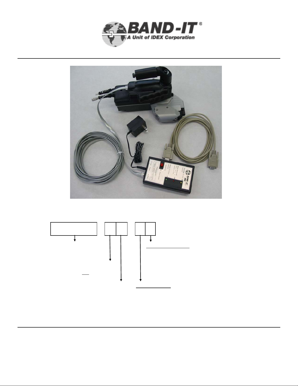
XIT6000-CA
Owner’s Manual
3/8” Tie-Lok®Tool
XIT6000 - C A - 0 1
Base part nu m ber
Major re vision level
revisi ons are not
revis i ons are c om patibl e
BAND-IT-IDEX, Inc.
A Unit of IDEX Corporation
4799 Dahlia Street Denver, CO 80216-3070 USA
P: 1-800-525-0758 F: 1-800-624-3925
compatible
Minor re vision level
www.BAND-IT-IDEX.com
Packagi n g opt i on s :
0- Packaged with tool only
1- Packaged with all accessories
Trigger opti ons:
0- St andard on-tool trigger
1- Connect i o n for remot e trigger (t ri gger not inc l uded)
Document # XIT177 Rev E
© Copyright
1
BAND-IT-IDEX, Inc. 2005
All rights reserved
Page 2
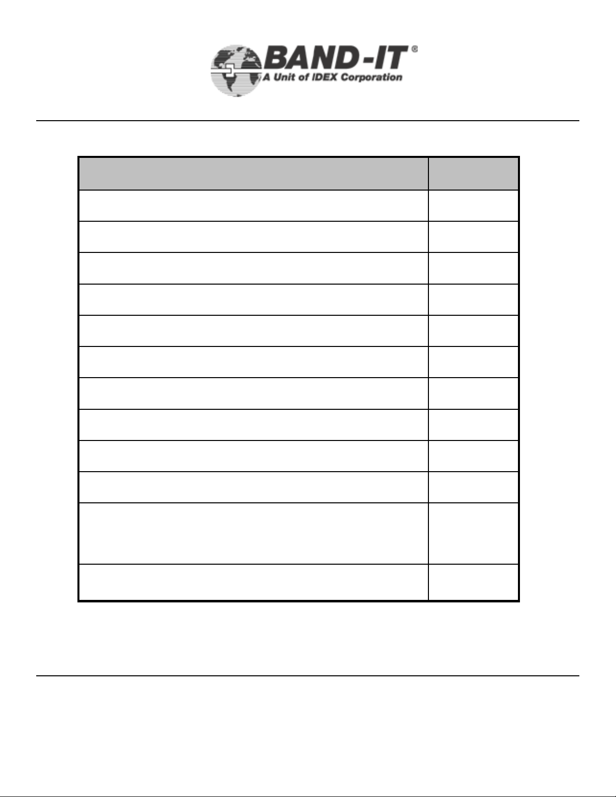
Table of
Contents
XIT6000-CA
3/8” Tie-Lok®Tool
PageTable of Contents
3Warranty & Safety Guidelines
4-6Parts Identification
7-8Air Supply Requirements
8 Tool Overview
9-12Setup and Assembly Instructions
Monitoring System
13-14Remote Operations Fixturing Tips
15Operating Instructions
16Operating Tips
17-21Troubleshooting
22-29Preventative Maintenance
30-36Tension Cylinder Pressure
37-38Tool Calibration Procedure
BAND-IT-IDEX, Inc.
A Unit of IDEX Corporation
4799 Dahlia Street Denver, CO 80216-3070 USA
P: 1-800-525-0758 F: 1-800-624-3925
www.BAND-IT-IDEX.com
2
Document # XIT177 Rev E
© Copyright
BAND-IT-IDEX, Inc. 2005
All rights reserved
Page 3

Warranty &
XIT6000-CA
Safety Guidelines
Warranty:
For Warranty information visit the following URL
www.BAND-IT-IDEX.com/Warranty.html
Safety Guidelines
• Read this manual and become familiar with the tool before installing any
clamps.
• Protective eyewear should be worn when connecting and disconnecting
the tool to compressed air sources and during operation.
• Wear appropriate gloves for handling steel while operating this tool,
applying stainless steel clamps and removing scrap clamp tail.
3/8” Tie-Lok®Tool
• Clamp tensi oning can be immediately stopped by releasing the tool
trigger system.
• When applying clamps, care should be taken to insure fingers and loose
clothing are not in the way of the clamp being applied.
• Never attempt to clamp objects which have a potential to burst, shatter
or otherwise cause bodily harm.
• Disconnect air supply and electrical power prior to maintenance and
disassembly of tool components.
• Liquids or lubricants should never be put into the ai r lines.
BAND-IT-IDEX, Inc.
A Unit of IDEX Corporation
www.BAND-IT-IDEX.com
Document # XIT177 Rev E
© Copyright
4799 Dahlia Street Denver, CO 80216-3070 USA
P: 1-800-525-0758 F: 1-800-624-3925
3
BAND-IT-IDEX, Inc. 2005
All rights reserved
Page 4
Parts
XIT6000-CA
Identification
Production tools will experience wear of specific parts. Preventative maintenance, including
regular cleaning and lubrication, will reduce the replacement frequency of these parts. To
maximize life, use synthetic gel lubricant containing Teflon. See (pages 22-29) for tool
maintenance. When repairing tools, threaded fasteners should be secured using a small amount
of Loctite, Red – High strength.
Replacement Parts
Part #
I19691
I13887
I17687
I19787
Description
3/8” Tie-Lok®Tool
Quantity per
Tool
1Knife Assembly
1Knife Pin
2Knife Pin Access Screw
1Blade
I20487
I20387
I18487
A38487
I19187
I16387
Note- Parts and part numbers are subject to change. Please have tool model and
serial #’s available when calling the factory for service assistance.
Lubricant (synthetic gel lubricant containing
Teflon)
1Blade Pin
1Tension Pin
1Tension Gripper
2Gripper Spring
1Tension Block
BAND-IT-IDEX, Inc.
A Unit of IDEX Corporation
4799 Dahlia Street Denver, CO 80216-3070 USA
P: 1-800-525-0758 F: 1-800-624-3925
www.BAND-IT-IDEX.com
4
Document # XIT177 Rev E
© Copyright
BAND-IT-IDEX, Inc. 2005
All rights reserved
Page 5
Parts
XIT6000-CA
Identification
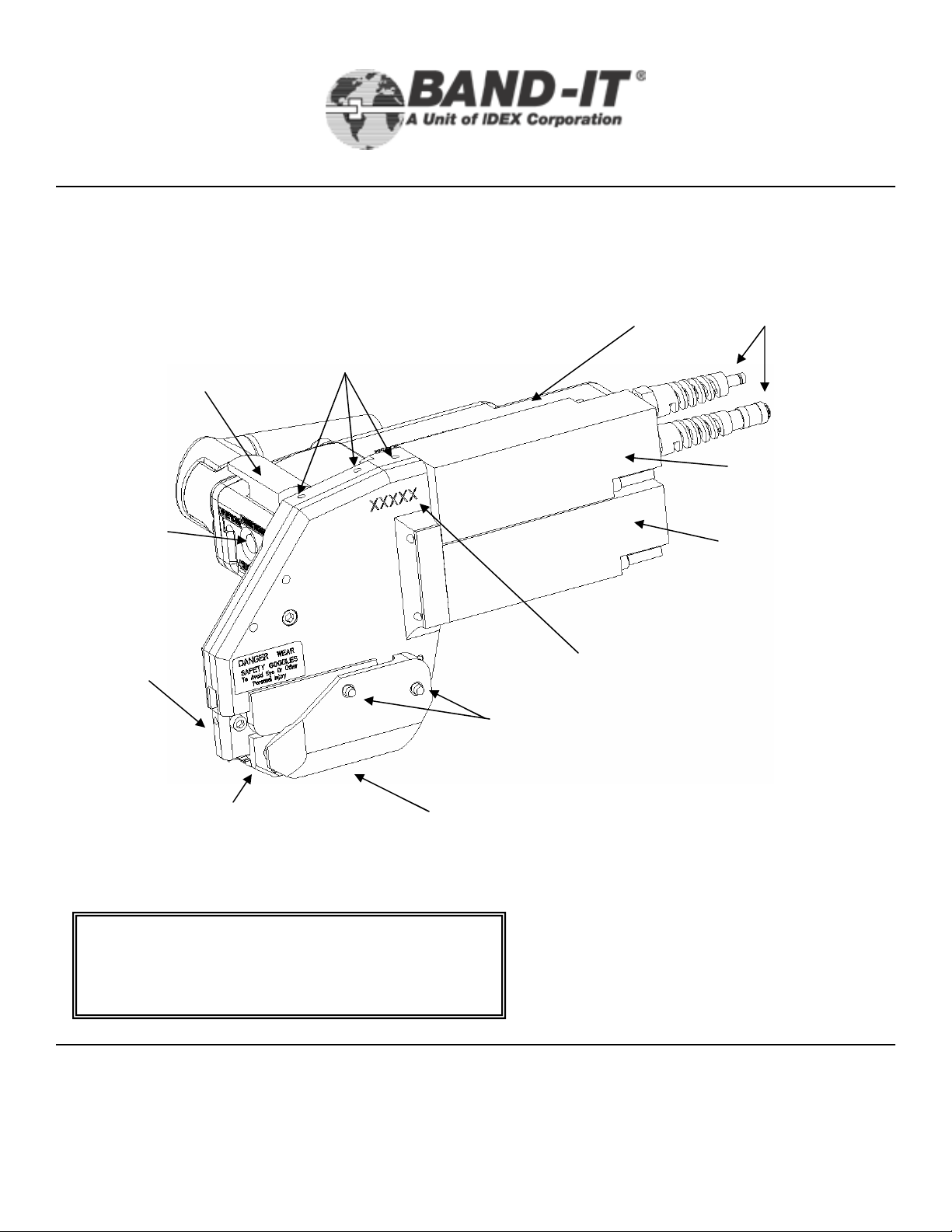
Operating
Trigger
Reset
Button
XIT6000-CA Tool Body
Tool Hanger
mounting
holes
Model I.D.
Plate
3/8” Tie-Lok®Tool
Quick Connect
Air Couplings
(Do not add
lubricants)
Cut-off
Cylinder
Tension
Cylinder
Tool Head
with Cutter
Knife
Assembly
and Blade
Maintenance
Flip Cover
Flip Cover
Tightening Screw
Important: Before disassembling tool, be sure
to shut-off air supply on the Air Controller
Module. Unplug the data cable going to the tool.
BAND-IT-IDEX, Inc.
A Unit of IDEX Corporation
www.BAND-IT-IDEX.com
Serial #
Location
Quick Release Pins
(removable from opposite side)
Document # XIT177 Rev E
© Copyright
4799 Dahlia Street Denver, CO 80216-3070 USA
P: 1-800-525-0758 F: 1-800-624-3925
5
BAND-IT-IDEX, Inc. 2005
All rights reserved
Page 6
Parts
XIT6000-CA
Identification
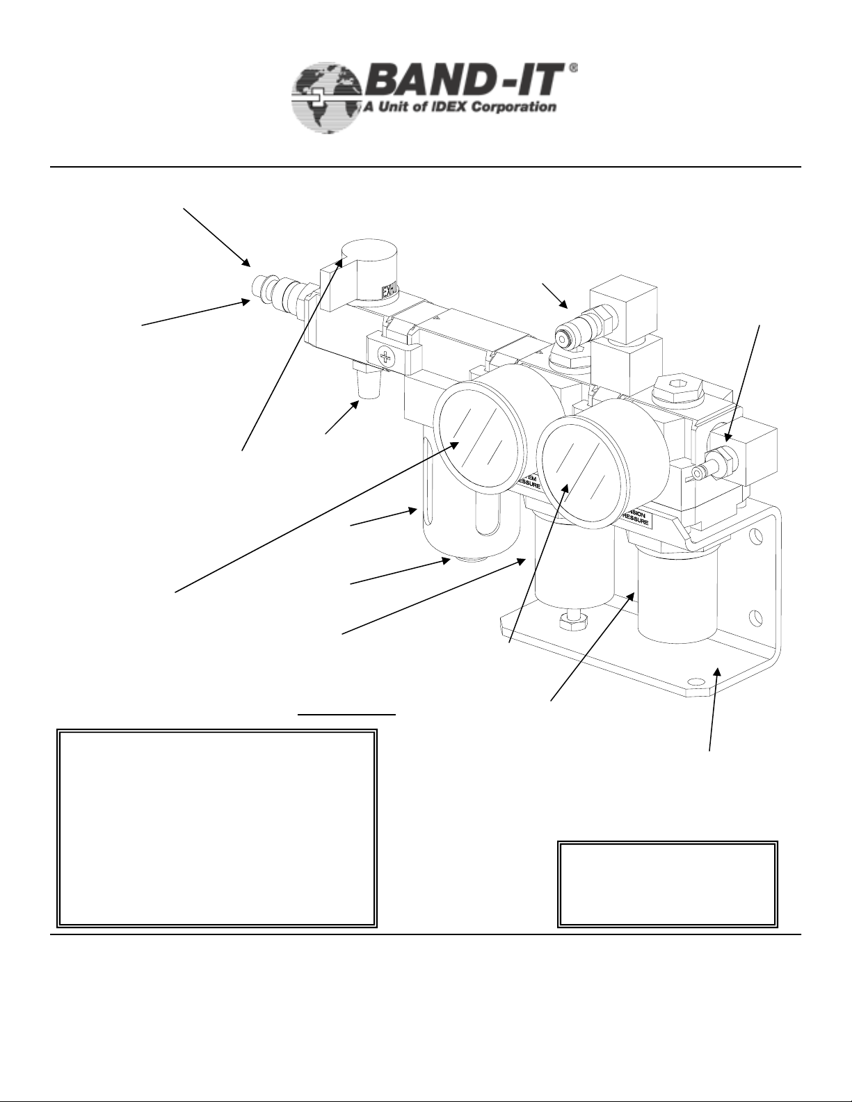
Inlet Air Supply
Quick Disconnect
Use one of two
quick-disconnects
supplied or remove
and use 1/4” NPT
fitting
Air Shut-Off Valve
3/8” Tie-Lok®Tool
Air Controller Module
Cut-off
Air Outlet
Tension
Air Outlet
Exhaust
Muffler
Filter
Fluid Drain
Cut-off Air
Pressure
Gauge
Air Filter Environment:
Standard Filters/Regulators
incorporate polycarbonate bowls and/or
observation windows. DO NOT use in
an environment that will expose the
above mentioned components to
synthetic fluids, organic solvents ,
chemicals, cutting lubricants, thread
lock solutions or similar materials.
Release
Valve
Cut-off Air
Pressure Regulator
Factory set to 105
PSI Do not adjust
Tension Air
Pressure Gauge
Tension Air
Pressure Regulator
Pull Regulator
Knob and twist to
adjust tension,
push to lock
Mounting Bracket
Unit may be mounted
on wall or bench
Note: Air Controller Module
must be mounted and operated
in a horizontal position.
BAND-IT-IDEX, Inc.
A Unit of IDEX Corporation
4799 Dahlia Street Denver, CO 80216-3070 USA
P: 1-800-525-0758 F: 1-800-624-3925
www.BAND-IT-IDEX.com
6
Document # XIT177 Rev E
© Copyright
BAND-IT-IDEX, Inc. 2005
All rights reserved
Page 7
Air System
XIT6000-CA
Requirements
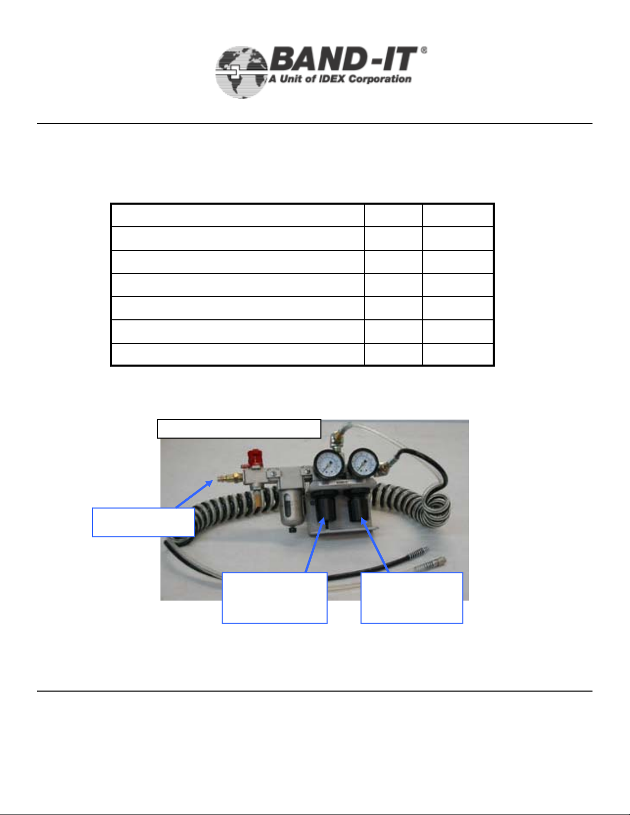
The XIT6000-CA is a pneumatic tool that needs a clean and dry supply of air to operate.
For proper tool performance, the air requirements at the inlet to the BAND-IT Air
Controller Module of the XIT6000-CA must be:
1.5Inlet Supply Air Flow (SCFM)
*The BAND-IT Air Controller Module includes a filter to meet these requirements.
3/8” Tie-Lok®Tool
MaxMinItem
140100Inlet Supply Pressure (PSI)
5Particle Size In Air Supply (microns)
20% RHAir Moisture Content
7560Tension Pressure Settings (PSI)
110100Cut-off Pressure Setting (PSI)
Inlet air supply
BAND-IT-IDEX, Inc.
A Unit of IDEX Corporation
Air Controller Module
Cut-off
Pressure
Adjustment
www.BAND-IT-IDEX.com
Tension
Pressure
Adjustment
Document # XIT177 Rev E
© Copyright
4799 Dahlia Street Denver, CO 80216-3070 USA
P: 1-800-525-0758 F: 1-800-624-3925
7
BAND-IT-IDEX, Inc. 2005
All rights reserved
Page 8

XIT6000-CA
Tool Overview
Pneumatic System:
The pneumatic valves and cylinders all have seals or o-rings that wear out. Once the orings in the cylinders begin to wear, air is allowed to pass by the pistons in the cylinders,
which can affect the performance of the tool and cause the calibration of the tool to drift.
The cylinders are permanently lubricated, but premature wear can be caused by debris in
the air lines or the presence of water and oil, which can break down the lubrication. The 4way valves in the tool can be affected by debris and oil in the air lines that cause the valve
to stick and not operate as is necessary. Over time, the mechanical linkages in the tool will
also begin to wear. This wear will cause some drift in the calibration of the tool, but does not
have the same effect of wear in the air system.
To address the potential problems associated with the air supply, BAND-IT recommends the
use of an Air Booster System. In addition to filtering and drying the air, it will also maintain a
steady pressure of 100 -110 PSI assisting the proper function of the tool.
Tool Function:
3/8” Tie-Lok®Tool
The XIT6000-CA tool functions by using an incoming supply of air to actuate a mechanical
linkage. The linkage connects to a gripping system that outputs a force on the band portion
of the Tie-Lok ties. The output of the tool varies depending upon the air pressure supplied
to the tool. If the pressure is increased, the output force increases.
During the tension cycle the tool will continue to pull up or tension the band until the
appropriate tension is reached. The tool stops tensioning when the pressure in the tension
cylinder equals the inlet tension pressure coming from the air controller module. After the
tool has pulled tensioned the tie, the tool switches over to the cutoff cycle. At this point in
the cycle the gripping system maintains the force on the tie and a knife is actuated down
which forms a dimple and cuts the band.
Equipped with the tool, there is a tension cylinder pressure monitor (Red/Green Light Data
Acquisition) that measures the air pressure in the tension cylinder when the tool switches
over to cut-off. The pressure is captured from the tension cylinder immediately before
cutoff, while the tension force is being held in the band. The electronics of the tool takes this
pressure reading and calculates a number for the output force based upon an equation.
This equation is derived from a capability study of a normal XIT6000-CA tool fitted with a
M28090 calibration device (see Tool Calibration, page 37) at the initial build of the tool.
BAND-IT-IDEX, Inc.
A Unit of IDEX Corporation
www.BAND-IT-IDEX.com
Document # XIT177 Rev E
© Copyright
4799 Dahlia Street Denver, CO 80216-3070 USA
P: 1-800-525-0758 F: 1-800-624-3925
8
BAND-IT-IDEX, Inc. 2005
All rights reserved
Page 9

Setup &
XIT6000-CA
Assembly
3/8” Tie-Lok®Tool
Instructions
The XIT6000-CA shipping container includes: Air Controller Module,
XIT6000-CA tool body, coiled air line, owner’s manual, tool kit and
Tension Cylinder Pressure Monitoring Device kit.
Initial Setup - Pneumatics
• Connect the tool body to the Air Controller Module using the included Coiled Hose
Assembly. The hose assembly includes both a clear and black hose. Each hose
end includes a female and male fitting, arranged to prevent reversing of
connections.
• Connect Air Controller Module to air source (assure air supply meets
requirements on page 7) and turn RED Shut-off Valve counter clockwise to
pressurize tool (supply position).
• Make sure Cut-off Air Pressure Gauge located on the left side of the module
reads a pressure of 100 PSI min/ 110 PSI max.
• The Tension Air Pressure Gauge monitors the tension applied to the clamp tail.
Air pressure at the Tension Gauge should be 60-75 PSI for BAND-IT 3/8” TieLok®Ties.
Initial Setup – Electronics
Refer to pages 30- 36 of this manual for setup and operating instructions for the
Tension Cylinder Pressure Monitoring System.
Setting the Tool Air Pressure
The air pressure supplied to the XIT6000-CA tool should be adjusted so that the output
force of the tool falls between 333-368 lbs. To correctly set the air pressure from the air
controller module going to the tool, attach the calibration device (page 37) and hook up the
air supply. Activate the tool by depressing the trigger. When the tool stops moving, read
the display on the calibration device. If the force on the readout is not within the Ford
Engineering Specification of 333-368 lbs, adjust the tension air pressure between 60-85 psi
and repeat this test until the force is within range. Press the tool reset button to release the
force and remove the calibration device. If the tool cannot be adjusted into this range by
varying the pressure between 60-75 psi, then the tool is either out of calibration or is not
working properly and should be returned to BAND-IT.
BAND-IT-IDEX, Inc.
A Unit of IDEX Corporation
4799 Dahlia Street Denver, CO 80216-3070 USA
P: 1-800-525-0758 F: 1-800-624-3925
www.BAND-IT-IDEX.com
9
Document # XIT177 Rev E
© Copyright
BAND-IT-IDEX, Inc. 2005
All rights reserved
Page 10
Setup &
Assembly
Instructions
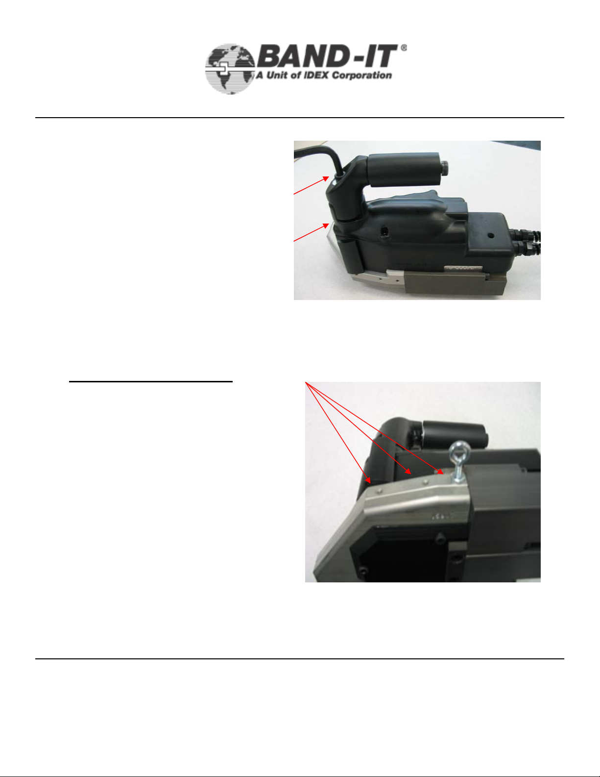
Handle adjustment:
• Using 1/4” hex key (supplied), adjust
the Support Arm/Handle to ergonomically
match the operators hand.
• Be sure not to adjust the Handle too far
outward (beyond interlocking legs) or the
handle will not function properly or
provide support to the operator.
XIT6000-CA
3/8” Tie-Lok®Tool
Hanger Support Instructions:
1. A steel hanger can be utilized for
supporting the tool with a
counterbalance. Full weight of tool
should not be supported by a single
hole.
2. A hanger can be installed (as
shown) into one of the three
supplied threaded holes. To
prevent internal damage, only 1/8”
of the hanger threads should be
threaded into the hole.
3. Secure the hanger against the tool
body with a lock nut as shown. This
will prevent movement of the
hanger during tool operation.
4. Use a light application of Loctite,
Red, high-strength, on threads of
hanger prior to installation.
Hanger Mount
BAND-IT-IDEX, Inc.
A Unit of IDEX Corporation
4799 Dahlia Street Denver, CO 80216-3070 USA
P: 1-800-525-0758 F: 1-800-624-3925
www.BAND-IT-IDEX.com
10
Document # XIT177 Rev E
© Copyright
BAND-IT-IDEX, Inc. 2005
All rights reserved
Page 11
Setup &
Assembly
Instructions
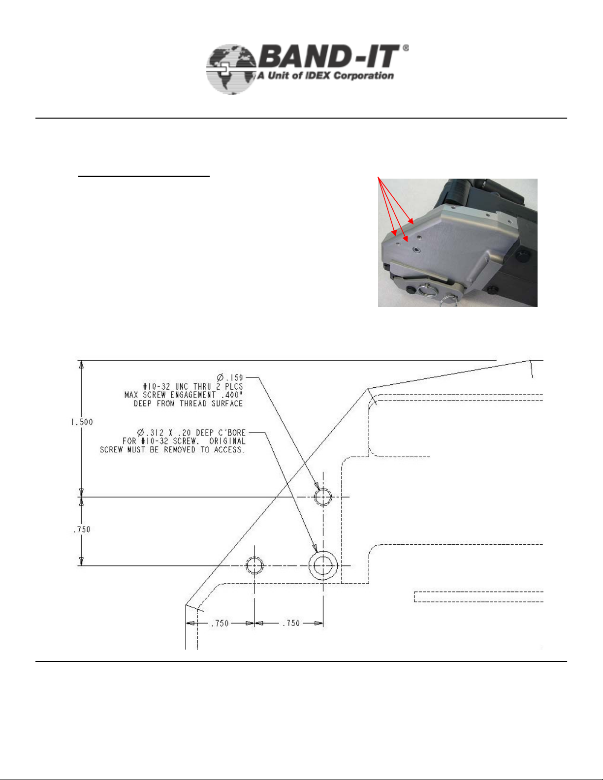
Three additional fixture mounting holes are available
to assist with mounting the XIT6000-CA. Thread
size is #10-32 for each of the holes. Usable thread
depth is .400” for two of the three fixture holes. One
hole is utilized to attach and lock the tool body
halves together. This hole may also be used for
fixturing, provided the #10-32 cap screw is replaced
with a similar threaded screw with appropriate
thread length secure the two halves together in
addition to fixturing.
XIT6000-CA
3/8” Tie-Lok®Tool
Fixture Mounting LocationsFixture Locating Points
BAND-IT-IDEX, Inc.
A Unit of IDEX Corporation
4799 Dahlia Street Denver, CO 80216-3070 USA
P: 1-800-525-0758 F: 1-800-624-3925
www.BAND-IT-IDEX.com
11
Note: Hole locations
are .750” to
centerline of holes
and edge of tool as
indicated by the
detail to the left.
Document # XIT177 Rev E
© Copyright
BAND-IT-IDEX, Inc. 2005
All rights reserved
Page 12
Setup &
XIT6000-CA
Assembly
3/8” Tie-Lok®Tool
Instructions
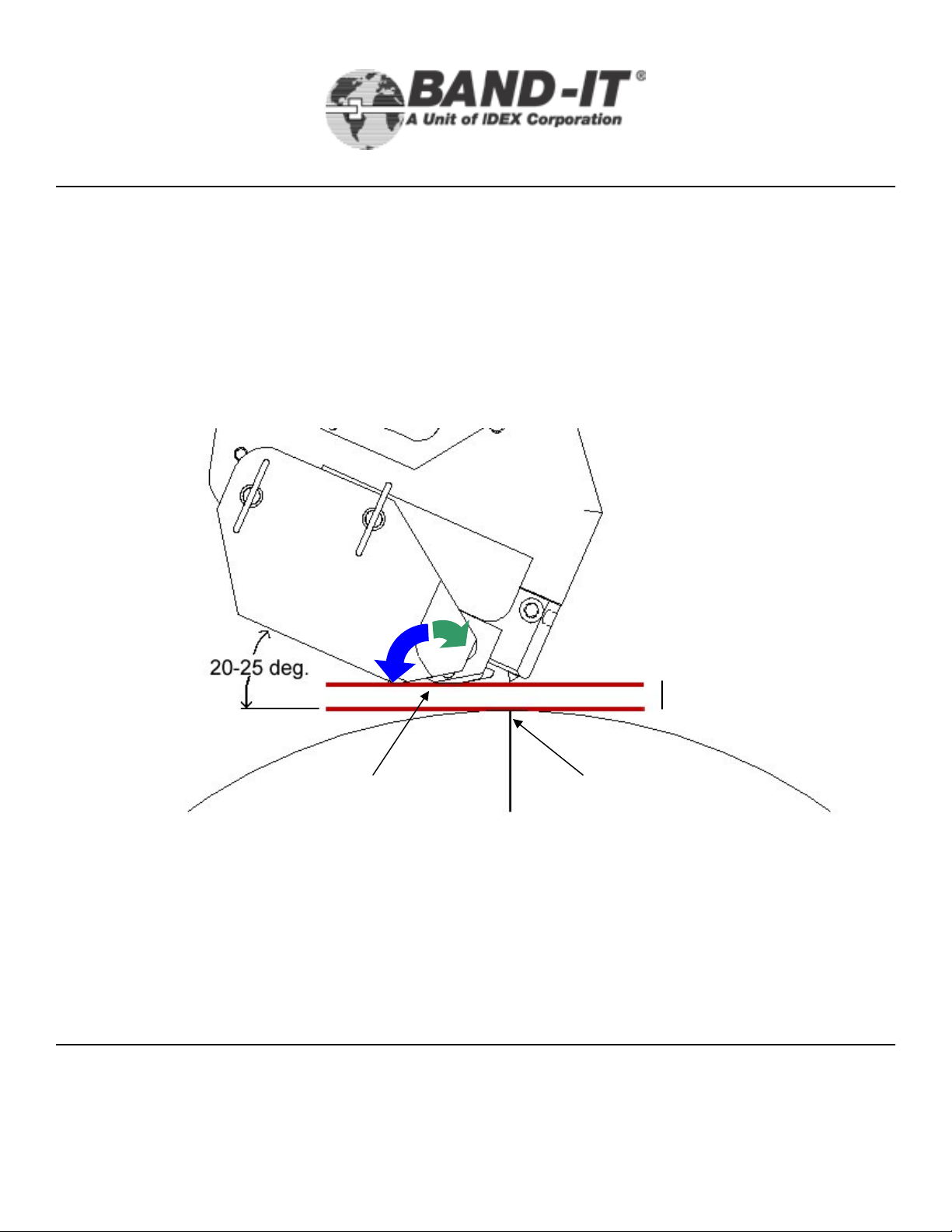
Part of insuring that the tool is producing a strong lock is making sure that it approaches
the application correctly and is fixtured to allow repeatability of application. The tool
should approach the surface of the wheel tangent to the point on the wheel where the
buckle of the band is to be applied. The tool should be allowed to float 1/8” – 1/4”
above the surface of the wheel to allow the buckle to move to the proper position for
cut-off. Once the tool begins tensioning, the band will pull the tool down to the surface
of the wheel.
1/8” – 1/4”
Buckle LocationPivot Point
As the band is tensioning, the tool may rotate clockwise up to 5 degrees about the pivot
point (Green Arrow). During the cut-off cycle, the tool must be allowed to rotate counterclockwise up to 35 degrees (Blue Arrow). Because of this movement, BAND-IT
recommends that the tool be mounted in a fixture that will provide adequate
rotation during both cycles.
BAND-IT-IDEX, Inc.
A Unit of IDEX Corporation
4799 Dahlia Street Denver, CO 80216-3070 USA
P: 1-800-525-0758 F: 1-800-624-3925
www.BAND-IT-IDEX.com
12
Document # XIT177 Rev E
BAND-IT-IDEX, Inc. 2005
© Copyright
All rights reserved
Page 13

Remote Operation
XIT6000-CA
& Fixturing Tips
3/8” Tie-Lok®Tool
Supplement
XIT6000 Orientation Requirements:
• The XIT6000-CA-XX tool has a number of Tool/Clamp/Object Being Clamped
orientation requirements that must be followed in order to reach an acceptable
end result.
• In concept, the fixture maker should attempt to replicate the natural human
wrist/elbow/shoulder motions that would occur when operating the tool in the
hand-held configuration, allowing the tool to float along a plane through the
entire Tension (pull-up) and Cut-Off (lock) process.
• The tool MUST:
• Be permitted to adjust spatially to permit the clamp being applied to
achieve optimal attachment force(s).
• Contact the object being clamped at the tool’s natural optimal point
without restricting or forcing.
• Suggestions Include:
• The tool fixture should be able to accommodate some longitudinal rotational
movement, i.e. “wrist like”, at the final moment of applied tension. The
purpose being, to allow the tool freedom of movement to orient itself in its best
natural orientation as relates to the clamp and the object-being-clamped.
• A home or neutral position should be established at the optimal final
position with +/- 10-12½ degrees of rotational freedom being allowed
from the pivot point.
• The tool fixture should be able to accommodate some extensive movement,
i.e. “elbow like”, during the tension phase to allow the tool to be “pulled” up to
the object being clamped.
• Deviations from accommodating the natural inclination of the tool/clamp/object
being clamped, may negatively impact the integrity of the final assembly. The
clamp should fully rest upon the object being clamped at the time of final
tension and cut-off. If the tool can not reach the object being clamped and
attempts to cut-off, the clamp and/or lock may not form optimally.
• Attention MUST be paid to the plane angle of the applied clamp at the
prescribed position per FORD ES 6L2A 1A176 A_.
BAND-IT-IDEX, Inc.
A Unit of IDEX Corporation
4799 Dahlia Street Denver, CO 80216-3070 USA
P: 1-800-525-0758 F: 1-800-624-3925
www.BAND-IT-IDEX.com
13
Document # XIT177 Rev E
© Copyright
BAND-IT-IDEX, Inc. 2005
All rights reserved
Page 14

Remote Operation
XIT6000-CA
& Fixturing Tips
3/8” Tie-Lok®Tool
Supplement
XIT6000 Configured for Remote Actuation:
• The XIT6000-CA - 11 has trigger option 1 and is a modified version o f the base unit XIT6000–
CA - 01. The XIT6000-CA-01 is manually operated via the incorporated thumb actuation lever.
The XIT6000-CA-11 is configured to allow remote operation via palm button or other device
permitting the tool to be incorporated into the customer’s fixture or assembly process.
• The modification consists of deactivating the thumb lever actuation switch and installing a twincoiled 10-ft X 1/8” O.D. hose to accomplish the same tas k via the use of a remote actuation
device such as a palm button or other device that can provide a pneumatic si gnal to pilot the
tension control valve.
• Various actuation devices can be incorporated based upon end user requirements. Basic
schematic for 2-way & 3-way valves included below. The valve should be set up in the
normally closed mode and upon opening the circuit a supply of air is provided.
• The customer is responsible for inco rporating this too l into their process, BAND-IT is ava ilable
to provide advice and recommendations.
Remote trigger: 2-way valve
Hose from tool
(male quick disconnect)
Remote trigger: 3-way valve
Hose from
tool (male)
Actuate
to stop
tool
Supply Hose from
tool 90-120 PSI
(female quick disconnect)
Hose from tool
(male)
If more than one trigger is used,
connect in series. All need to be
actuated to run the tool.
Supply Hose from
tool 90-120 PSI
(female)
BAND-IT-IDEX, Inc.
A Unit of IDEX Corporation
Actuate
to start
tool
Multiple Triggers
Actuate to
stop tool
Supply Hose from
tool 90-120 PSI
(female)
www.BAND-IT-IDEX.com
Actuate to
start tool
Connect the 2 hoses extending
from the tool to the ports of the
valve. As the hoses are not
marked, they may need to have
their connection on the valve
reversed if the remote trigger
does not start the tool.
Document # XIT177 Rev E
© Copyright
4799 Dahlia Street Denver, CO 80216-3070 USA
P: 1-800-525-0758 F: 1-800-624-3925
14
BAND-IT-IDEX, Inc. 2005
All rights reserved
Page 15

XIT6000-CA
Operating Tips
Tie Installation:
When installing a tie, a random visual check to verify the presence of a dimple after
the tie has been applied is recommended. The dimple is the locking element of an
installed band. The XIT6000-CA forms a dimple into the band with the punch. By
controlling and monitoring the items that are needed to form a good lock, an operator
can help insure that the band will be applied correctly without having to inspect every
assembly.
These items are:
•Adequate air pressure and volume (see page 6,7)
•Setting the tool air pressure (see page 7,9)
•Following recommended PM Schedule (see page 24)
•Checking the Tool Punch Height (see page 25)
•Proper tool calibration (see page 37)
•Fixture mounting the tool properly (see page11-14 )
3/8” Tie-Lok®Tool
For best performance and to extend tool life:
• Follow preventative maintenance and parts replacement instructions
(page 24) at appropriate service intervals.
• Do not remove factory applied lubrication from inside tool or use degreaser.
• Do not spray any lubricant or cleaner into the Quick Connect Air Couplings.
• Use nominal recommended tension setting (listed on page 7-9). Higher pressure
may not result in a tighter clamp, but increases the likelihood of clamp tail jamming
and premature worn parts.
• Do not over-tighten Knife Pin Access. Over tensioning of these screws may result
in stripping screw threads.
• For maintenance beyond what is described in this manual, consult BAND-IT.
BAND-IT-IDEX, Inc.
A Unit of IDEX Corporation
www.BAND-IT-IDEX.com
Document # XIT177 Rev E
© Copyright
4799 Dahlia Street Denver, CO 80216-3070 USA
P: 1-800-525-0758 F: 1-800-624-3925
15
BAND-IT-IDEX, Inc. 2005
All rights reserved
Page 16

Operating
XIT6000-CA
Instructions
3/8” Tie-Lok®Tool
2.5”
1. Insert clamp tail into tool as shown. Clamp tail length
extending into tool must be at least 2.5” (6.4 cm) long. The
head of the tool should rest against the buckle. Note - Do not
activate tool while inserting clamp tail. This can cause
clamp tail to jam in the Tension Block Assembly.
2a. Begin tensioning clamp by pushing and holding down
operating trigger
b. Band should be applied to a uniform solid surface allowing
the buckle adequate support during the clamp locking and
clamp tail cut-off operation.
3. While tensioning clamp, hold tool slightly tipped forward.
This will assist proper clamp installation. Continue to hold
down operating trigger until tool completely tensions and
cuts off clamp. Release trigger after cut off.
4. After clamp is completed, clamp tail scrap must be
removed from tool. Clamp tail scrap is not ejected
automatically. Tool is now ready for next clamp.
BAND-IT-IDEX, Inc.
A Unit of IDEX Corporation
4799 Dahlia Street Denver, CO 80216-3070 USA
P: 1-800-525-0758 F: 1-800-624-3925
www.BAND-IT-IDEX.com
16
Document # XIT177 Rev E
© Copyright
BAND-IT-IDEX, Inc. 2005
All rights reserved
Page 17

XIT6000-CA
Troubleshooting
Tool Fails to Fully Tension Clamp:
Failure to fully tension the clamp can be caused by a variety of factors. The two most
common factors are: incorrect tension pressure and problems in the Tension Block
Assembly.
• Check tension pressure setting on Tension Pressure Gauge of Air Controller Module.
Adjust pressure per the settings in the Setup & Assembly Instructions section found on
(pages 9-12).
• After air pressure settings are verified or corrected, if failure to fully tension clamps
continues, evaluate the clamp tail dimple pattern. If elongated dimples are present, the
problem may be with the Tension Block.
3/8” Tie-Lok®Tool
Normal clamp tail
dimple pattern.
If a problem is indicated, follow the instructions on page 23 to remove the tension block
assembly.
Examine the Tension Block components for excess lubrication. Refer to lubrication
instructions on pages 23, 26 - 28.
If dirt or debris is visible, follow the cleaning instruction on page 23.
Examine the Tension Block and Gripper for wear (see below).
If wear is indicated, follow the instructions on page 23 to replace the worn parts.
BAND-IT-IDEX, Inc.
A Unit of IDEX Corporation
www.BAND-IT-IDEX.com
Clamp tail dimple pattern indicates
problem in the tension block
assembly.
Document # XIT177 Rev E
© Copyright
4799 Dahlia Street Denver, CO 80216-3070 USA
P: 1-800-525-0758 F: 1-800-624-3925
17
BAND-IT-IDEX, Inc. 2005
All rights reserved
Page 18

XIT6000-CA
Troubleshooting
3/8” Tie-Lok®Tool
Tool fails to cut off clamp tail:
• The Inlet Air Pressure may be low. Check air supply to Air Controller Module. Cut-off
Pressure Gauge should indicate 100 PSI minimum, 110 PSI maximum. See pages 7-8 for air
supply requirements.
• The scrap clamp tail from the previous clamp may not have been removed. Press the Reset
Button to release the tension on the clamp and remove the scrap clamp tail.
• The Cutter Blade or Knife may be worn. See below for Cutter Blade inspection and
replacement.
• Note: The Flip Cover Tightening Screw is factory tensioned to a torque value of 12 -15 inch
pounds and will need to be retensioned after the quick release pins are reinstalled upon
completion of maintenance. Over tightening of screw can result in the quick release pins to
bend. This would then make them hard to remove or insert.
Cutter Blade inspection and replacement:
1. Loosen the Flip
Cover Tightening
Screw (see note
above) to remove both
Quick Release Pins as
shown.
3. Remove the Cutter
Blade Pin and Cutter
Blade. The Cutter
Blade has two working
edges and can be
rotated 180° t o use the
second edge prior to
replacement.
2. Remove Flip
Cover and
Tension Block
Assembly for
cleaning and
lubrication.
4. When installing
the Cutter Blade
Pin, use a small
screwdriver to
push the front
gripper toward the
back of the tool.
BAND-IT-IDEX, Inc.
A Unit of IDEX Corporation
4799 Dahlia Street Denver, CO 80216-3070 USA
P: 1-800-525-0758 F: 1-800-624-3925
www.BAND-IT-IDEX.com
18
Document # XIT177 Rev E
© Copyright
BAND-IT-IDEX, Inc. 2005
All rights reserved
Page 19

Trouble Shooting
XIT6000-CA
Matrix
3/8” Tie-Lok®Tool
Symptom Probable cause Recommended Fix Page
Tool will not
tension
properly (i.e.
slipping, slow
etc.)
Tool will not
c ut off clamp
tail
Rear tension block slippi ng,
therefore tool does not
reach c u t off tensi on.
Front gripper slipping Remove and inspect front gripper and gripper guide arm.
Dirty front and r ear gripper
interfaces
Air leaks when tri gger is not
activated
Worn f li p cover and tool
body
Water or oil in pneumatic
lines.
Tool cutti ng before full
tension appli ed.
Premature release of trigger Hold trigger down until tool completes cut off cy cle 15
Fluctuating facility air
pressure
Worn knife/ b lade Remove and r eplace knife and blade. Refer to
Timing valve adjustment Ver ify timing. If required, remove right side body and
Rear tension block slippi ng,
therefore tool does not
reach c u t off tensi on.
Coiled hose line has air leak Verify no air leaks i n coiled hose assembly . Remove and
Front gripper slipping Remove and inspect front gripper and gripper guide arm.
Red four wa y valve
malfunction
Worn blade pin or housing Remove and replace blade pin and/ or housing. 18
Remove and inspect gripper block assembly. Replac e as
required.
Replace if worn.
Remove and c lean contact surfaces. 23
Listen for air leaks. C heck r ed valve , Air li nes, and
replace as required. No air leaks allowed. Remove and
replace as requi red or contact BAND- IT.
Inspect insi de of flip cover and bottom of tool body for
excessive wear . Replace flip cover as required. For tool
body wear contact BAND-IT for evaluation.
Pur ge pneumatic lines and red four way valve assembly.
Install a desiccant air dryer or si milar which meets tool set
up requirements (see manual).
Ver ify timing. If required, remove righ t si d e body and
adjust timing valve. Replace if damaged.
Ver ify facili ty air pressure meets tool set up requirements
(see manual). Air booster system might be required.
maintenanc e schedule.
adjust timing valve. Replace if damaged.
Remove and inspect gripper block assembly. Replac e as
required.
replace as required.
Replace if worn.
Remove clean and inspect. Replac e as required. *
23
*
29
28
*
29
7,8
22
29
23
7,8
*
BAND-IT-IDEX, Inc.
A Unit of IDEX Corporation
4799 Dahlia Street Denver, CO 80216-3070 USA
P: 1-800-525-0758 F: 1-800-624-3925
www.BAND-IT-IDEX.com
19
Document # XIT177 Rev E
© Copyright
BAND-IT-IDEX, Inc. 2005
All rights reserved
Page 20

Trouble Shooting
-
XIT6000-CA
Matrix
3/8” Tie-Lok®Tool
Symptom Probable cause Recommended Fix Page
Tool will not cut
off clamp tail -
Continued.
Loose clamp
after cut-off
Linkage components
damaged, ca using
interference
Cut-off c ylinder seal
damaged or leaking
Cut off pneumatic air leak Verify Coiled Hose Assembly is fr ee of air leaks. Remove
W ater or oi l i n pneumatic
lines.
Screws holding Cutter Knife
Pin too long or loose
Coiled hose line is reversed
(i.e. cut off pressure is
actually going to tension
cylinder.
Improper tool use Verify ope rator properly trained and familiar with tool manual. 8,15, 16
Tension setting too low Adjust Air C ontroller Module's tension setting p er instructions. 7
Remove tool left side body and verif y linkage mechanism.
Remove and replace damage as required or contact BANDIT.
Remove left si de tool body and verify seal i ntegrity *
handle cover and i nspect for leaks on gray ano dized valve
assembly and red valve assembly. Inspect for leaks in
pneumatic system.
Purge pneumatic lines and re d four way valve assembly.
Install a desiccant ai r dryer or similar equipment which meets
tool requirements (see manual).
Verify proper length sc rews and Cutter Knif e P in seated
properly.
Verify coiled hose ai r line from right side of control module
enters bottom fitting on tool.
26,27,28
*
7
22
6,7
Improper buckle location or
application
Tool cuts clamp tail befor e
reaching f ull tension.
Worn Cutter K n ife / Cutter
Blade
Air leaks when tri gger is not
activated
Tool will not
operate when
trigger is
depressed
Control Module air pressure
valve is in "off" position.
Pinched coil hose line Loosen fitting on coiled hose assembly where it enter s tool
Kinked or pinc hed air line Remove right si de h andle and i nspect air lines. Remove and
Tension piston interfer ence
with hanger sc rew holes.
Quick disconnect fittin gs
not positively engaged.
BAND-IT-IDEX, Inc.
A Unit of IDEX Corporation
Locate buckle on smallest radi us area. Buckle must be
supported underneath during appli cation. C ontact BAND-IT
for applicati on verification / recommendation.
Verify timing. If required remove right side handle and adjust
Timing Valve. Replace i f damaged.
Remove and replace Cutter K nife and Cutter Blade. Refer to
maintenance schedule.
Listen f or air leaks. Check red valve, Air li nes, and replace as
required. No air leaks allowed. Remove and replace as
required or contact BAND-IT.
Rotate Control Module valve to open positi on. Verify gauges
read air pr essure.
body.
replace as required.
Loosen Hanger Sc rew on top of tool. Thread engagement
cannot exceed .125 in.
Disconnect and f irmly reconnect. 6,7
www.BAND-IT-IDEX.com
12,14,16
29
18
Contact BAND
IT for
assistance
6
7
29
10
Document # XIT177 Rev E
© Copyright
4799 Dahlia Street Denver, CO 80216-3070 USA
P: 1-800-525-0758 F: 1-800-624-3925
20
BAND-IT-IDEX, Inc. 2005
All rights reserved
Page 21

Trouble Shooting
XIT6000-CA
Matrix
3/8” Tie-Lok®Tool
Sympt om Probable cause Recom m ended Fix Page
Tool will not
operate when
trigger is
depressed
Clamp will not
insert into tool
Handle will not
adjust
Control Module air
pressure valve is in "off"
position.
Pinched c oil hose line Loosen fitting on coiled hose as sembly where it
Kinked or pinched air line Remove right side handle and inspect air lines.
Tensi o n pis ton
interferenc e with hanger
screw holes.
Control Module air
pressure valve is in "off"
position.
Clamp tail inside tool Remove clamp tail, if jammed remove
Knife is in forward
position.
Wrong clamp type for Verify proper tool for selected clamp. 9
Handle nut is
damaged/misaligned.
Rotate Control Module valve to open position.
Verify gauges read air pressure.
enters tool body.
Remove and repl a ce as requir ed.
Loosen Hanger Screw on top of tool. Thread
engagement cannot exceed .125 in.
Rotate Control Module valve to open position.
Verify gauges read air pressure.
maintenance/flip cover and remove clamp
material.
Remove or replace knife. Verify missing and or
damaged linkage.
Remove handle assembly and inspect
nut/housing for damage. Replace as required.
6
5
29
10
6
15,18
22,26
10
* = for additional assistance, contact BAND-IT
BAND-IT-IDEX, Inc.
A Unit of IDEX Corporation
4799 Dahlia Street Denver, CO 80216-3070 USA
P: 1-800-525-0758 F: 1-800-624-3925
www.BAND-IT-IDEX.com
21
Document # XIT177 Rev E
© Copyright
BAND-IT-IDEX, Inc. 2005
All rights reserved
Page 22

XIT6000-CA
Maintenance
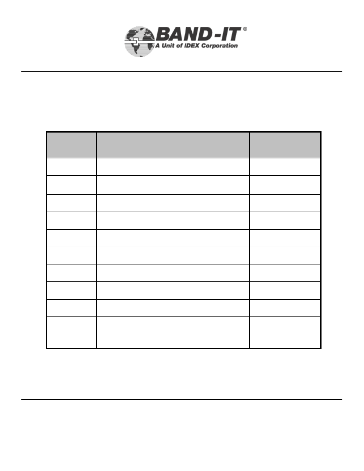
The XIT6000-CA requires preventative maintenance as indicated below. The “Clamps
Installed” column indicates how many clamps can be installed between each servicing.
Tool Preventative Maintenance:
The tool has some wear components that must be checked and replaced on a certain
schedule. BAND-IT has developed a Preventative Maintenance (PM) schedule to help
facilitate these requirements. An excerpt from this PM Schedule is shown below. If tools
are experiencing difficulties during function or there audible air leaks coming from inside
the handle, the tool should be returned to BAND-IT-IDEX, Inc. for servicing.
3/8” Tie-Lok®Tool
Preventative Maintenance Schedule
Clamps
Installed
Maintenance
Item
Maintenance
Action
Clean & Re-LubricateTension Block Assembly12,500
Clean & Re-LubricateFlip Cover12,500
Clean & Re-LubricateMechanical Linkage25,000
Clean & Re-LubricateTool Head25,000
Rotate (page 18)Cut-off Blade25,000
ReplaceCut-off Knife Assembly25,000
Front Gripper25,000
Clean, re-lubricate, and inspect for
multiple broken teeth
ReplaceCut Off Blade50,000
Replace AssemblyTension Block Assembly50,000
Replace gripperFront Gripper50,000
BAND-IT-IDEX, Inc.
A Unit of IDEX Corporation
4799 Dahlia Street Denver, CO 80216-3070 USA
P: 1-800-525-0758 F: 1-800-624-3925
www.BAND-IT-IDEX.com
22
Document # XIT177 Rev E
© Copyright
BAND-IT-IDEX, Inc. 2005
All rights reserved
Page 23

XIT6000-CA
Maintenance
Knife Assembly Replacement:
3/8” Tie-Lok®Tool
A) Remove Cutter Blade as described on page 18.
B) Remove the Knife Pin Access Screws. These are
special length screws.
Important: When repairing tools, threaded fasteners
should be secured using Loctite, Red - high strength.
To remove Cutter Knife Pin the Knife Assembly
must be in its uppermost position indicated by the
Cutter Knife Pin in line with the access hole. If not
aligned, connect the tool to the Air Controller
Module. Open the Air Shut-off Valve to
momentarily pressurize the tool. Close the valve
and disconnect the tool from the Air Controller
Module. Then push out the Cutter Knife Pin with
a piece of wire (for example, a bent paper clip).
BAND-IT-IDEX, Inc.
A Unit of IDEX Corporation
4799 Dahlia Street Denver, CO 80216-3070 USA
P: 1-800-525-0758 F: 1-800-624-3925
www.BAND-IT-IDEX.com
Once the pin is removed, grasp the Knife
Assembly with a pair of needle-nose pliers and
pull out of tool head. Examine for wear and
replace if needed.
Re-install all parts in reverse order. After the
Maintenance Flip Cover is installed and Quick
Release Pins are in place, apply tension to the
Maintenance Flip Cover Tightening Screw,
torque to 12-15 inch pounds.
Document # XIT177 Rev E
© Copyright
23
BAND-IT-IDEX, Inc. 2005
All rights reserved
Page 24

XIT6000-CA
Maintenance
3/8” Tie-Lok®Tool
Tension Block Assembly Maintenance:
Remove the Maintenance Flip Cover by loosening the Maintenance Cover Tightening Screw on the Maintenance
Flip Cover and removing both Quick Release Pins as shown on page 18.
Tension Block
Assembly
Tension
Gripper
Tension Block Assembly
Compression Spring - 2
Tension Pin
Tension Gripper
Tension Block
Tension Block Assembly, inspection and parts replacement:
Disassembly:
• Lift and remove the Tension Block Assembly from the notch on the Tension Arm.
• Push out the Gripper. remove the loose Gripper Springs.
• Push out the Gripper Pin.
Inspection:
• Inspect and replace the Tension Block if worn.
• Inspect and replace the Tension Gripper if worn.
• Inspect and replace the Gripper Pin if worn.
Reassembly:
• Lubricate the Gripper surfaces as shown on page 28.
• Install the Gripper in the Tension Block.
• Lubricate the Tension Pin surfaces as shown on page 28.
• Install the Gripper Pin in the Tension Block.
• Reinstall the Gripper Springs.
• Reinstall the Tension Block Assembly. Be careful to engage
the Tension Block Pin with the notch on the Tension Arm.
• Lubricate the Maintenance Flip Cover as described on page 28.
• Reinstall the Maintenance Flip Cover and insert Quick Release Pins.
• Tension the Flip Cover Tightening Screw (12-15 in-lbs) to complete reassembly.
BAND-IT-IDEX, Inc.
A Unit of IDEX Corporation
www.BAND-IT-IDEX.com
Document # XIT177 Rev E
© Copyright
4799 Dahlia Street Denver, CO 80216-3070 USA
P: 1-800-525-0758 F: 1-800-624-3925
24
BAND-IT-IDEX, Inc. 2005
All rights reserved
Page 25

XIT6000-CA
Maintenance
Tool Punch Height:
The punch can be checked for excessive wear and damage by measuring the height it
extends above the knife surface. To do this follow the directions listed below.
1. Pinch the line coming from the tension regulator on the controller module and
depress the tool trigger. This will activate the cut-off and extend the knife assembly.
2. Thoroughly clean the punch tip and knife surface so that both are free of debris.
3. Measure the height that the punch sticks out above the surface of the knife.
4. When the punch height drops below .120" (3.18mm), or shows evidence of chipping,
replace the punch and/or knife.
Punch
Punch Height
.120” min.
3/8” Tie-Lok®Tool
Knife
BAND-IT-IDEX, Inc.
A Unit of IDEX Corporation
www.BAND-IT-IDEX.com
Document # XIT177 Rev E
© Copyright
4799 Dahlia Street Denver, CO 80216-3070 USA
P: 1-800-525-0758 F: 1-800-624-3925
25
BAND-IT-IDEX, Inc. 2005
All rights reserved
Page 26

XIT6000-CA
c
n
e
3/8” Tie-Lok®Tool
mechanical linkage points
n
i
n
a
M
• Remove the Maintenance Flip Cov e r. Examine all moving parts and linkages for wear.
• Using an air nozzle, gently clean the parts of any dirt and metal filings in the tensioning
cavity.
• Using cotton swabs or a short bristled brush, continue to wipe away any foreign debris
and purge once again with the air nozzle.
• After thoroughly cleaning all moving parts, re-lubricate all surfaces. Following are
lubrication instructions.
• For mechanical parts lubrication use a synthetic gel lubricant containing Teflon.
a
t
e
Procedure for disassembly to clean and lubricate the
1) Remove the two screws located at the back of the
cylinders. Remove third screw holding the side bodies
together. Holding the tool in place, gently lift the side
cover exposing the mechanical linkage. This side
cover is a close fit and may require a slight rocking
motion to separate the cover from the tool.
2) a) Examine the linkage for over-all condition such as
dirt, metal filings, liquid contamination and lubrication.
b) Examine the upper cylinder (tension cylinder), for
evidence of air leaks, noted by residue around the
piston.
3) Clean tool cavity, including tool body, linkage, and
already removed tool cover.
BAND-IT-IDEX, Inc.
A Unit of IDEX Corporation
4799 Dahlia Street Denver, CO 80216-3070 USA
P: 1-800-525-0758 F: 1-800-624-3925
www.BAND-IT-IDEX.com
26
Document # XIT177 Rev E
© Copyright
BAND-IT-IDEX, Inc. 2005
All rights reserved
Page 27

M
a
XIT6000-CA
c
n
e
3/8” Tie-Lok®Tool
n
i
n
a
t
e
4) Lubricate the removed cover as shown with red arrows above. Also,
lubricate the tool body, linkage and Tension Block Assembly as shown on page 28.
5) Inspect all mechanical linkage for lubrication, proper placement and refit cover.
6) Secure the tool side cover by inserting and tensioning (2) #10 – 32 X 4”
length cap screws through the Cylinder Housing and into the Cover. Apply
a light dab of red Loctite thread loc to one or two threads to prevent loosening during
operation.
BAND-IT-IDEX, Inc.
A Unit of IDEX Corporation
4799 Dahlia Street Denver, CO 80216-3070 USA
P: 1-800-525-0758 F: 1-800-624-3925
www.BAND-IT-IDEX.com
27
Document # XIT177 Rev E
© Copyright
BAND-IT-IDEX, Inc. 2005
All rights reserved
Page 28

XIT6000-CA
Maintenance
Lubrication – Follow recommended intervals – Use a synthetic gel lubricant containing
Teflon for the internal parts as shown and described. Lubricate all pivot points and internal
surfaces of maintenance flip cover with a light coating of the lubricant.
Caution – Excessive amounts of lubricant may result in gripper slippage, requiring a
full repeat of cleaning process.
Lightly lubricate all
points indicated with
Maintenance Flip Cover
every 12,500 cycles
red arrows.
3/8” Tie-Lok®Tool
Tool mechanics
every 25,000 cycles
After the Maintenance
Flip Cover is cleaned,
lubricated, installed and
Quick Release Pins are
in place, apply tension
to the Maintenance Flip
Cover Tightening
Screw. Torque to 12-15
inch lbs. Refer to
pages 5, 18.
BAND-IT-IDEX, Inc.
A Unit of IDEX Corporation
4799 Dahlia Street Denver, CO 80216-3070 USA
P: 1-800-525-0758 F: 1-800-624-3925
www.BAND-IT-IDEX.com
28
Tension Block Assembly
every 12,500 cycles
Note: Ensure no
lubrication is present in
the center of Gripper.
(indicated by the blue
circle)
Document # XIT177 Rev E
© Copyright
BAND-IT-IDEX, Inc. 2005
All rights reserved
Page 29

XIT6000-CA
Maintenance
Procedure to adjust the timing of the clamp tail cut-off:
Bottom airline
3/8” Tie-Lok®Tool
Additional information on timing, page 31.
The Timing Valve will be affected over time by
contaminants in the air system. Moisture, dirt
particles, oil and solvents can cause blockage or
fluctuations in the tool performance.
Cut-off timing set too fast will not allow the clamp to
achieve the desired tension before switching to the
cut-off function causing a loose clamp. Cycle should
be .9 – 1.3 seconds.
Cut-off timing set too slow may slow production and
cause operator to twist the tool during application.
This may damage tool.
Procedure:
1) Remove the two cap screws in the Handle Cover with
a 9/64” hex key. Remove cover and lay aside. Cap
screws are of different length, note their position during
their removal.
BAND-IT-IDEX, Inc.
A Unit of IDEX Corporation
2) The Brass Needle Valve used to adjust timing is
highlighted in view to the left.
3) To adjust: Hold the valve in position being careful not
to kink tubing inside tool. Start by gently turning the
Adjusting Valve Screw clockwise until snug. Back out
the Adjusting Screw counterclockwise 1 1/2 turns.
This should be the proper setting, yielding a .9-1.3
second delay.
4) To test and verify proper adjustment: Connect the tool
to the Air Control Module, then turn supply valve on.
Gently kink the coiled air supply tube connected to the
bottom Quick Connect Air Coupling (top photo), then
activate the Tool Trigger. This action causes the tool
to cut off, allowing the timing to be reviewed. A dju stin g
the Timing Screw in by ½ turn will slow the t o ol’s cutoff action. Adjusting the Timing Screw out by a half
turn increases the speed of the cut-off activation.
Repeat this entire step until timing is set at a .9 – 1.3
second delay. Caution: Setting timing to less than
.9 may result in loose clamps.
5) See page 34 for alternative procedural information.
www.BAND-IT-IDEX.com
Document # XIT177 Rev E
© Copyright
4799 Dahlia Street Denver, CO 80216-3070 USA
P: 1-800-525-0758 F: 1-800-624-3925
29
BAND-IT-IDEX, Inc. 2005
All rights reserved
Page 30

XIT6000-CA
Tension Cylinder
Pressure Monitoring
System
The Tension Cylinder Pressure Monitoring System provides an indication, but not confirmation, of clamp tail
tension by transmitting a pressure reading from the Tension Cylinder via a Pressure Transducer. The
transducer signal is recorded when the Cut-off Cylinder begins to move. The Cut-off Cylinder begins to move
when the tool has reached maximum tension. The force applied by the tension cylinder is calculated from the
transducer signal. The Monitoring System also provides a gateway to pass the number of completed cycles of
both the tension and cutoff cylinders to the data collection device. Data, in ASCII format, from the Monitoring
System is sent via an RS-232 serial port to a Data Collection Device (not part of the monitoring system).
3/8” Tie-Lok®Tool
The Tension Cylinder Pressure Monitoring System consists of: 1) Breakout Box with reset switch, one each
green, red, and yellow LEDs, RS232 port, Data Connector, Power Input, and Signal Output (9V Out, 3.5mm
phono jack) 2) 9VDC Power Supply 3) RS232 Cable, approx. 10 ft length 4) 15 foot Data Cable.
Initial Set Up:
•Secure the Breakout Box away from shock and vibration.
•Connect the Serial Cable from the Breakout Box to the Data Collection Device, (e.g. Computer)
•Connect the 8 wire, Ethernet Cable to the receptacles on both the tool and Breakout Box.
•If desired, the “9V Out” signal output on the Breakout Box can be connected to a customer supplied device. The
signal could be used to shut off air supply to the tool should the monitoring system indicate force is out of range.
•Plug the 9VDC power supply into a 120VAC 60Hz wall outlet and the cable to the power connector on the
Breakout Box.
•The green LED indicator on the Breakout Box should be lit indicating the system is ready to monitor the Tension
Cylinder pressure.
•If the yellow LED indicator is lit this indicates the tool has not been detected. Insure the Data Cable is
connected and routed away from sources of electrical noise.
•For information on data capture, refer to page 32.
•To verify tool cut-off timing, refer to pages 29, 34.
BAND-IT-IDEX, Inc.
A Unit of IDEX Corporation
www.BAND-IT-IDEX.com
Document # XIT177 Rev E
© Copyright
4799 Dahlia Street Denver, CO 80216-3070 USA
P: 1-800-525-0758 F: 1-800-624-3925
30
BAND-IT-IDEX, Inc. 2005
All rights reserved
Page 31

XIT6000-CA
Tension Cylinder
Pressure Monitoring
System
Operation:
• When the system calculates a force outside the predetermined range the red LED will be lit,
error message will be appended to output data string, and the voltage at the “9V Out” signal
output will change from 9 VDC to 0 VDC. This condition could be caused by: tension
pressure set incorrectly, an air leak in the tool, cut-off timing set too short, or low air supply
volume to the tool.
• Correct the problems as required and cycle the tool by installing a clamp or using the
M28090 device. If the red LED is still lit, continue to look for and correct problems related to
the air system.
• Note: Pushing the Reset Button on the Breakout Box will clear an error, return the LED to
green, and reset the voltage at the signal output to 9 VDC. This is not normally needed,
unless the 9V out directly controls a shutoff device to the tool. See page 35 for additional
means to reset the tool.
• When the breakout box first detects a connected tool, it will output the tool information: Total
number of cycles and tool serial number.
3/8” Tie-Lok®Tool
Example of Data Output:
Program: X75301 *Revision: C
Clamp # PSI LBF Tool # Error
30 11111
31 69.0 359 11111
32 64.8 337 11111
33 58.1 302 11111 LOW
34 72.7 378 11111 HIGH
• The suggested operating range is 333-368 LBF.
• LBF = The calculated force applied to the clamp tail +/- 15 LBF.
• Example:
• Clamp number 33 shows a low output and clamp number 34 shows a high output for this
example.
• Clamp number 30 shows output when tool is first connected.
• *Note: Tool display should be Revision C. Earlier versions can be easily upgraded, contact
BAND-IT Engineering.
• Actual ASCII output, items in [ ] are output only if an error is detected: (cycle number) 9
(Pressure) 9 (Force) 9 (serial number) [9 (error)] 10 13
BAND-IT-IDEX, Inc.
A Unit of IDEX Corporation
4799 Dahlia Street Denver, CO 80216-3070 USA
P: 1-800-525-0758 F: 1-800-624-3925
www.BAND-IT-IDEX.com
31
Document # XIT177 Rev E
© Copyright
BAND-IT-IDEX, Inc. 2005
All rights reserved
Page 32

XIT6000-CA
Tension Cylinder
Pressure Monitoring
System
Data Capture:
The XIT6000-CA Tension Cylinder Pressure Monitoring System can be used with many Data
Capturing Devices including any computer with Windows operating software.
• Any properly equipped tool will work with any XIT6000 data breakout box. The tool’s
serial #, clamp count and settings remain with the tool and will be detected by any
breakout box.
• Any software or hardware that can read the stated format can be used to collect data as it
is sent from the tool.
(i.e. Hyper Terminal provided with Windows (Windows2000: Start – Programs –
Accessories – Communications - Hyper Terminal). In settings, use the serial
port the tool is connected to instead of a phone number. Under “Connect using:”
select the port, typically COM1 or COM2. Using settings listed under
specifications.)
• Updates or customizations to the XIT6000-CA program can be sent to the customer using
a single executable file, no other software is required. Contact BAND-IT Engineering at 800525-0758.
3/8” Tie-Lok®Tool
Specifications:
• Power: 110 VAC to 9 VDC wall supply adapter (6 ft wire provided)
• Pressure range: will detect 25 to 125 PSI
• Output: 9-pin RS-232 serial (approx 10 ft cable provided)
• Serial settings:
o 2400 Baud
o8 bit
o No parity
o 1 stop bit
o ASCII formatted data
o No flow control
• Data format: Data columns (clamp number, PSI, estimated LBF and error if any)
separated by tabs, each record separated by line feed / carriage return, (hard return)
• Data is sent at each clamp installation cycle
• Accuracy:
o PSI: +/- 1.0
o LBF: +/- 15
BAND-IT-IDEX, Inc.
A Unit of IDEX Corporation
www.BAND-IT-IDEX.com
Document # XIT177 Rev E
© Copyright
4799 Dahlia Street Denver, CO 80216-3070 USA
P: 1-800-525-0758 F: 1-800-624-3925
32
BAND-IT-IDEX, Inc. 2005
All rights reserved
Page 33

XIT6000-CA
Tension Cylinder
Pressure Monitoring
System
Trouble Shooting Guide for the Tension Cylinder Pressure Monitoring System:
No data output: Is power connected? Is the tool connected with a 8 wire Ethernet cable? Is
the breakout box connected using a RS-232 serial cable? Null modem cables will NOT
work with this device. Check all tool and device settings including pinched air lines inside
tool housing and short cut-off timing adjustments. Some computer systems’ ports, to which
the Breakout Box is connected may be in use by another program. Close the program or
try another port.
Data output is garbled: Check the settings on the data capture device. Maximum cable
length can be 25 feet between breakout box and tool, maximum cable length between the
breakout box and data capture location can be 50 feet. (For longer serial cable run, we
suggest the use of a serial line amplifier).
3/8” Tie-Lok®Tool
Data output is garbled, or has false tool detection errors: Check for damaged cables.
Check cable routing, this system can be affected by outside interference. Keep cable away
from AC lines and other electrical noise generating sources.
Tool cycles, but no tool data is output: If the breakout box sends the header strings, but not
tool data, make sure the air lines inside tool handle are not pinched. This can be verified by
loosening the 2 handle screws and re-cycling the tool. Verify timing is properly adjusted,
refer to page 29. Verify the cable connections and settings are correct and the tool is
operating at correct tension cylinder pressure. This may indicate damage to the Ethernet
cable, pressure transducers or the circuitry inside the tool.
Tool cycles and system reads normal reading and lighting but clamp is loose
Refer to this XIT6000-CA manual. See air pressure settings, cleaning, lubrication,
preventative maintenance, parts replacement sections. Tool user is responsible for
ensuring clamp application.
:
BAND-IT-IDEX, Inc.
A Unit of IDEX Corporation
4799 Dahlia Street Denver, CO 80216-3070 USA
P: 1-800-525-0758 F: 1-800-624-3925
www.BAND-IT-IDEX.com
33
Document # XIT177 Rev E
© Copyright
BAND-IT-IDEX, Inc. 2005
All rights reserved
Page 34

XIT6000-CA
Tension Cylinder
Pressure Monitoring
System
Cut-off Timing Verification Procedure
1. This procedure requires the use of the M28090 Calibration Device.
2. This procedure requires the programmed Breakout Box to be -REV B- or later. If the
display on your tool is an earlier version, contact BAND-IT Engineering for a free
upgrade to the latest revision. See page 30, “Example of Data Output”
3. Prepare tool by connecting the M28090 Calibration Device per instructions included
with the device.
4. To switch the breakout box over to check cut-off timing, press and hold the reset button
on the break out box 3-4 seconds. When the button is released, the green LED will
begin flashing and the display will read “Ready to check timing: Press Trigger”
5. Press the trigger on the XIT Tool. The breakout box will output the measured
cut-off timing.
Examples:
“Timing OK! Time = 1.01 sec”
“Warning! Time = .91 sec”
“Timing Error! Time = .80 sec”
3/8” Tie-Lok®Tool
6. The green LED will light and remain solid if the timing is well within the
suggested range. The yellow LED will light if the timing is approaching the
limits of the suggested range; timing is OK, but may need to be adjusted soon.
The Red LED will light if the timing cycle is set too short or too long. Follow
instructions on page 29 for adjustments and re-check.
7. Press the reset button on the XIT6000 tool and the breakout box will reset,
flashing the green LED and be ready to check the timing again.
8. To switch from timing check mode to normal program operation, press and
hold the reset button on the breakout box for 3-4 seconds.
Note: The program will not switch into or out of timing mode unless it detects
an attached tool.
BAND-IT-IDEX, Inc.
A Unit of IDEX Corporation
www.BAND-IT-IDEX.com
Document # XIT177 Rev E
© Copyright
4799 Dahlia Street Denver, CO 80216-3070 USA
P: 1-800-525-0758 F: 1-800-624-3925
34
BAND-IT-IDEX, Inc. 2005
All rights reserved
Page 35

Tension Cylinder
Pressure Monitoring
System
Connections and Pinouts:
1. Data cable connection between tool and breakout box:
8-pin, 15 ft long, CAT5e cable provided. This cable carries both 12 VDC and 5 VDC
power, and 5 digital lines. Using a cable longer than 25 ft will degrade the signal and
may cause the tool to incorrectly report pressure readings.
Only connect the breakout box to the to ol. Never connect either the tool or breakout
box to any other device. Damage may occur to device, breakout box, or tool.
Before connecting the cable to the tool and breakout box, check for debris inside
both connectors. On rare occasions, debris inside the connectors will cause a short,
possibly damaging the electronics.
2. Serial connection:
XIT6000-CA
3/8” Tie-Lok®Tool
9-pin, approx 10 ft long, straight RS232 serial cable provided. Do not use a null
modem cable. (pins 1, 8 and 9 are inactive)
Pin 2: Data is sent on this pin in ASCII format
Pin 3: Not needed for normal operation. This pin is used to reprogram the breakout
box and needs to be connected for program updates.
Pin 4: This pin controls the breakout box reset and programming. Changing the
state of the this pin from low to high will force a reset on the Breakout box. If
needed, this can be used to clear errors.
Pins 6 and 7: Connected internally
See Figure for Pin Assignments:
3. 9V signal out:
3.5mm mono jack provided on breakout box.
Maximum current: 100 mA
BAND-IT-IDEX, Inc.
A Unit of IDEX Corporation
4799 Dahlia Street Denver, CO 80216-3070 USA
P: 1-800-525-0758 F: 1-800-624-3925
www.BAND-IT-IDEX.com
35
Document # XIT177 Rev E
© Copyright
BAND-IT-IDEX, Inc. 2005
All rights reserved
Page 36

Tension Cylinder
Pressure Monitoring
System
(Example of data collection using a Windows XP Operating System)
XIT6000-CA
3/8” Tie-Lok®Tool
1. Begin with Start Menu:\Programs\
Accessories\Communications\HyperTerminal
2. Type a connection name.
3. Click OK
6. Properties dialog box appears
7. Port Settings should be:
• Bits per second (2400)
• Data bits (8)
• Parity (None)
• Stop bits (1)
• Flow control (NONE)
Click OK
To check the cut-off delay timing, hold down the reset button on the breakout box for 3 seconds. You will see “Ready to
check timing” appear on the screen. Activate the tool and it will display the delay duration in decimals of seconds. Hold
down reset button for 3 seconds to return to main menu. See page 34.
4. “Connect to” dialog box appears
5. In the "Connect Using” text box,
choose COM1, Click OK
8. Hook up control box, two lines of header
information will appear on the screen:
Program / clamp, etc. Upon
connection, the current clamp
information and tool serial # will
appear. Tool is now ready.
9. To capture data- click Transfer, then click
Capture Text, enter a file name and
location, then click Start. *NOTE!
*Data will not be saved unless “stop”
is selected from this same menu.
BAND-IT-IDEX, Inc.
A Unit of IDEX Corporation
4799 Dahlia Street Denver, CO 80216-3070 USA
P: 1-800-525-0758 F: 1-800-624-3925
www.BAND-IT-IDEX.com
36
Document # XIT177 Rev E
© Copyright
BAND-IT-IDEX, Inc. 2005
All rights reserved
Page 37

Tool
XIT6000-CA
Calibration
BAND-IT’s use of the word calibration refers to the tool’s electronic output being
checked against a load measuring device. This is to insure that the electronic
calculation of the output force based on the supply pressure is still matched up with
the actual output force of the tool. To measure the actual output of the tool, BAND-IT
has developed a Calibration Device (M28090). Call BAND-IT for more information.
The Calibration Device is installed onto the tool in place of the flip cover. The tension
block of the tool presses up against the load cell on the calibration device when the
trigger of the tool is depressed, allowing the tension force to be captured. The force
is displayed on the readout. The direction of the tension force is shown by the white
arrow. See the M28090 manual for further information.
Tension Block Readout Load Cell
3/8” Tie-Lok®Tool
Flip Cover
XIT6000-CA-01 w/ Flip Cover Removed Installed M28090
To check the calibration of the tool, attach the M28090 calibration device at the tool’s
regular location. This will ensure that the data represents the performance of the tool
under normal operating conditions.
Once the M28090 is attached to the tool, hook up the air supply and actuate the trigger.
The M28090 will then display the tension force in the tool. The target tension force of
this calibration is 351 lbf, so the Tension Air Pressure of the Air Controller Module will
have to be adjusted (ensuring it remains within 60 to 75 psi) between tool cycles until
the target of 351 lbf is achieved. The tool may have to be reset and actuated several
times before the target point is reached.
BAND-IT-IDEX, Inc.
A Unit of IDEX Corporation
4799 Dahlia Street Denver, CO 80216-3070 USA
P: 1-800-525-0758 F: 1-800-624-3925
www.BAND-IT-IDEX.com
37
Document # XIT177 Rev E
BAND-IT-IDEX, Inc. 2005
© Copyright
All rights reserved
Page 38

Tool
XIT6000-CA
Calibration
Once the target tension force is attained, the value on the computer display screen
should be within ±15 lbf of the M28090 readout. Operation of the tool can begin if the
difference between the 2 readings is less than 15 lbf and within specifications (Ford
Engineering Specification of 334 to 368 lbf). These readings must be repeatable. If
the difference between the 2 readings is greater than 15 lbf, the tool needs to be sent
to BAND-IT-IDEX, Inc. for repair. Over a period of time, the 2 readings are likely to
drift apart, but they must remain within 15 lbf.
Once calibration is complete, press the tool reset button to release the force and then
remove the calibration device. Be sure to clean and lubricate the maintenance cover
before reinstalling the cover on the tool and inserting the Quick Release Pins shown
on page 5.
3/8” Tie-Lok®Tool
BAND-IT-IDEX, Inc.
A Unit of IDEX Corporation
4799 Dahlia Street Denver, CO 80216-3070 USA
P: 1-800-525-0758 F: 1-800-624-3925
www.BAND-IT-IDEX.com
38
Document # XIT177 Rev E
© Copyright
BAND-IT-IDEX, Inc. 2005
All rights reserved
 Loading...