

Page 1
Owner’s Manual
and Operating
Instructions
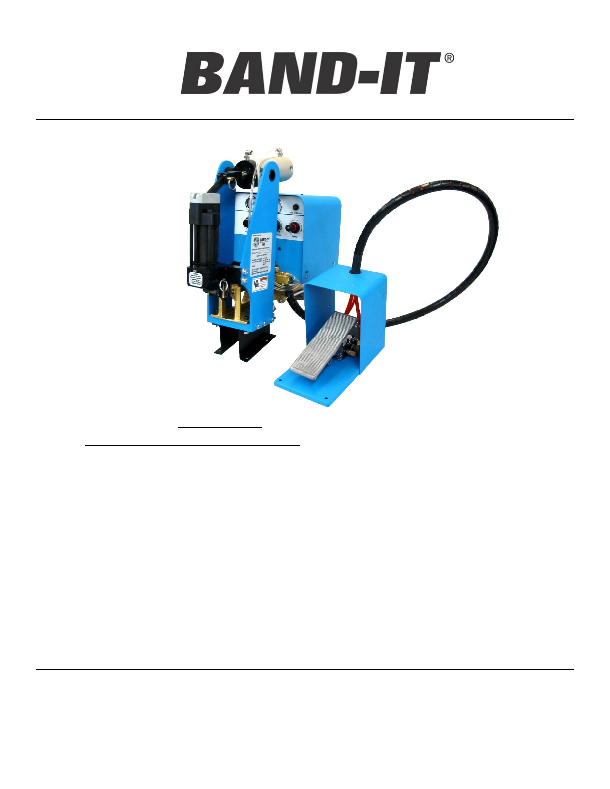
SM1700
Pneumatic
Center Punch
Tool
Page Information
2 Warranty and Safety Guidelines
3 Tool Overview and Installation
4 Air System Requirements
5 Setting Controls
6 Installing Clamps
7 Trouble Shooting Guide
8 Preventative Maintenance
9 Center Punch Head Information
10 Gripper Assembly
11-16 Replacement/Service Parts Identification
17 Air Connection Diagram
18 Factory Services
BAND-IT-IDEX, Inc.
A Unit of IDEX Corporation
Table of Contents
www.BAND-IT-IDEX.com
Document# SM1750 Rev. E
© Copyright
4799 Dahlia Street Denver, CO 80216-3070 USA
P: 1-800-525-0758 F: 1-800-624-3925
1
BAND-IT-IDEX, Inc. 2012
All rights reserved
Page 2

SM1700
Warranty and
Safety
Pneumatic
Center Punch
Tool
Warranty:
For Warranty information visit the following URL
www.BAND-IT-IDEX.com/Warranty.html
Safety Guidelines:
• Read this manual and become familiar with the tool before installing any clamps.
• Protective eyewear should be worn when connecting and disconnecting the tool to compressed air
sources and during operation.
• Wear appropriate gloves for handling steel while operating this tool, applying steel clamps and
removing the scrap clamp tail.
• Tool should be firmly mounted before installing clamps.
• Clamp tensioning or clamp tail retrieval can be immediately stopped by releasing pressure from the
foot pedal.
• When applying clamps, care should be taken to insure fingers and loose clothing are not in the way
of the clamp being applied.
• Never attempt to clamp objects which have the potential to burst, shatter or otherwise cause bodily
harm.
• Disconnect air supply prior to maintenance and disassembly of tool components.
Important advice and warning to user, Read before applying clamps:
The Center Punch type clamp’s lock and cut-off is achieved using considerable impact. This may cause
damage to the object being clamped.
Remember that a tighter clamp keeps the fitting more secure, but excess tension could damage the hose or
fitting. Fitting stem must have prominent barbs for proper retention inside the hose, but barbs must not be
sharp to prevent cutting into the hose. Hose, fitting and clamps must be compatible with each other and the
intended working environment. If in doubt, consult the hose or fitting manufacturer or call BAND-IT.
Clamping objects other than hose require similar precautions.
CAUTION: Improperly tightened clamps may result in dangerous hose assemblies, which could cause
injuries or property damage.
CAUTION: Abuse or use of hose outside the manufacturer’s recommended conditions may cause it to
quickly deteriorate and become a safety hazard. This could result in serious injury or property damage.
Inspect and test hose assemblies frequently. Repair or replace at the slightest sign of damage or
deterioration.
BAND-IT-IDEX, Inc.
A Unit of IDEX Corporation
4799 Dahlia Street Denver, CO 80216-3070 USA
P: 1-800-525-0758 F: 1-800-624-3925
www.BAND-IT-IDEX.com
2
Document# SM1750 Rev. E
© Copyright
BAND-IT-IDEX, Inc. 2012
All rights reserved
Page 3

SM1700
Tool Overview
and Installation
Pneumatic
Center Punch
Tool
Tool Overview:
• The SM1700 has been designed to automatically tension, lock and cut-off scrap tails of CP
style clamps. Type 201 Stainless Steel and Galvanized Carbon Steel, 5/8” wide CP style
clamps can be easily installed on hose assemblies or objects chosen by the operator.
• The SM1700 will sense when the desired clamp tail tension is achieved and automatically
switch to finalize the clamp. The completion of each clamp includes setting the lock while
simultaneously cutting off the excess clamp tail without requiring an assembly roll-up action.
• Operating tip: Choose a clamp diameter close to the size of the diameter of the object
being clamped. An oversized clamp may cause the End-of-Stroke safety switch to activate
and prevent finalizing the clamp with a lock and cut-off (see page 6, #6 and page 7, #4).
• The SM1700 directs compressed air through a foot pedal control to cycle the tool and
complete the installation of BAND-IT Center Punch Clamps. The foot pedal has a dual
action, forward (toe) and reverse (heel). During normal operation, the operator should fully
depress the foot pedal forward (toe), not removing this pedal pressure until the cycle has
completed and clamp tail is ready to be removed from the tool.
• Upon completion of the tension, lock and cut-off cycle, the operator should depress the heel
end of the pedal and remove the scrap clamp tail from the CP head.
• Operating tip: Operation can be stopped at any time by removing the operator’s foot
completely from the foot pedal control.
Tool Installation:
1. Recommended work bench height is 34” – 40”. This height is suggested as the optimum
range for operator comfort and safety during typical clamp applications. Locate the tool on a
solid surface making sure of ample clearance on either side for handling hose assemblies of
various lengths.
2. The air tool must be firmly secured as close to the front edge of the work bench as possible.
This will reduce interference of hose assemblies during clamp application. Install tool using
5/16” diameter fastening hardware (not supplied with tool).
3. Use of the SM1700 without properly maintained filtration and lubrication will void the
warranty. See page 4 for additional information on air supply requirements.
BAND-IT-IDEX, Inc.
A Unit of IDEX Corporation
4799 Dahlia Street Denver, CO 80216-3070 USA
P: 1-800-525-0758 F: 1-800-624-3925
www.BAND-IT-IDEX.com
3
Document# SM1750 Rev. E
© Copyright
BAND-IT-IDEX, Inc. 2012
All rights reserved
Page 4
SM1700
Air System
Requirements
Pneumatic
Center Punch
Tool
Important: For proper tool performance, follow air requirements for SM1700:
Line Pressure – 70 psi minimum,120 psi maximum (4.9 – 8.4 kg/cm^2, 483 – 827 kPa).
Volume - 3-5 CFM
Air Delivery system - ¼” minimum diameter air line with a ¼” N.P.T. connection.
Filtration – Follow typical filtration requirements of air operated equipment. The BAND-IT
supplied system includes a filter and lubricator.
Lubrication - Use DTE 24 hydraulic oil (BAND-IT part # S31589), oil drip-rate is verified by
cycling the machine. If one drop falls in sight glass within 10-25 cycles, the lubricator is
correctly adjusted. Excess oil will not benefit tool life and may lead to blockage of air
mufflers and a dirty environment.
Solvents - Liquids such as solvents or cleaners should never be added to the air system
through air lines.
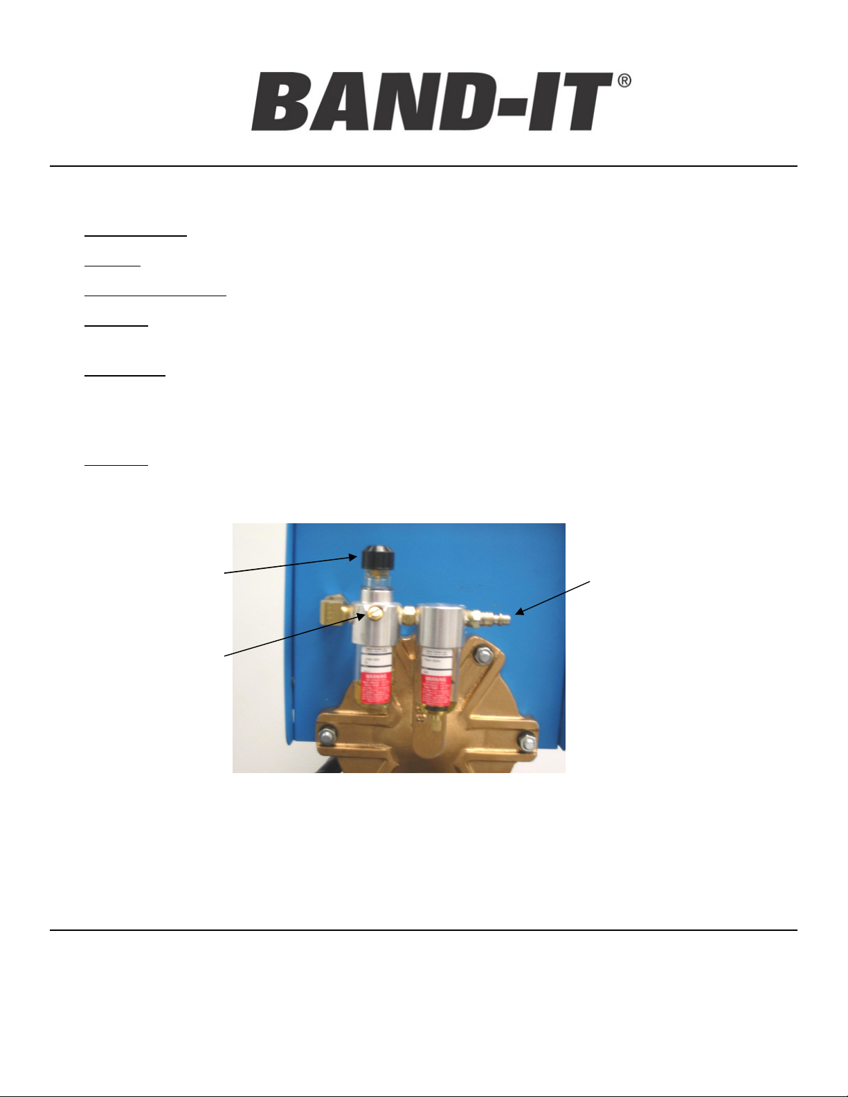
Oil drip rate
adjustment knob
Oil fill location
Caution!
Disconnect air
supply before
removing plug.
View of the back side of the SM1700 showing the supplemental
(included) filtering and lubrication system as well as the ¼” N.P.T.
air connection with a typical quick connect coupling.
Air connection
Warning: The lubricator should be refilled with DTE 24 hydraulic
oil only. The use of other oils may cause damage to the system.
BAND-IT-IDEX, Inc.
A Unit of IDEX Corporation
www.BAND-IT-IDEX.com
Document# SM1750 Rev. E
© Copyright
4799 Dahlia Street Denver, CO 80216-3070 USA
P: 1-800-525-0758 F: 1-800-624-3925
4
BAND-IT-IDEX, Inc. 2012
All rights reserved
Page 5
SM1700
Setting Controls
Center Punch
Tool
Pneumatic
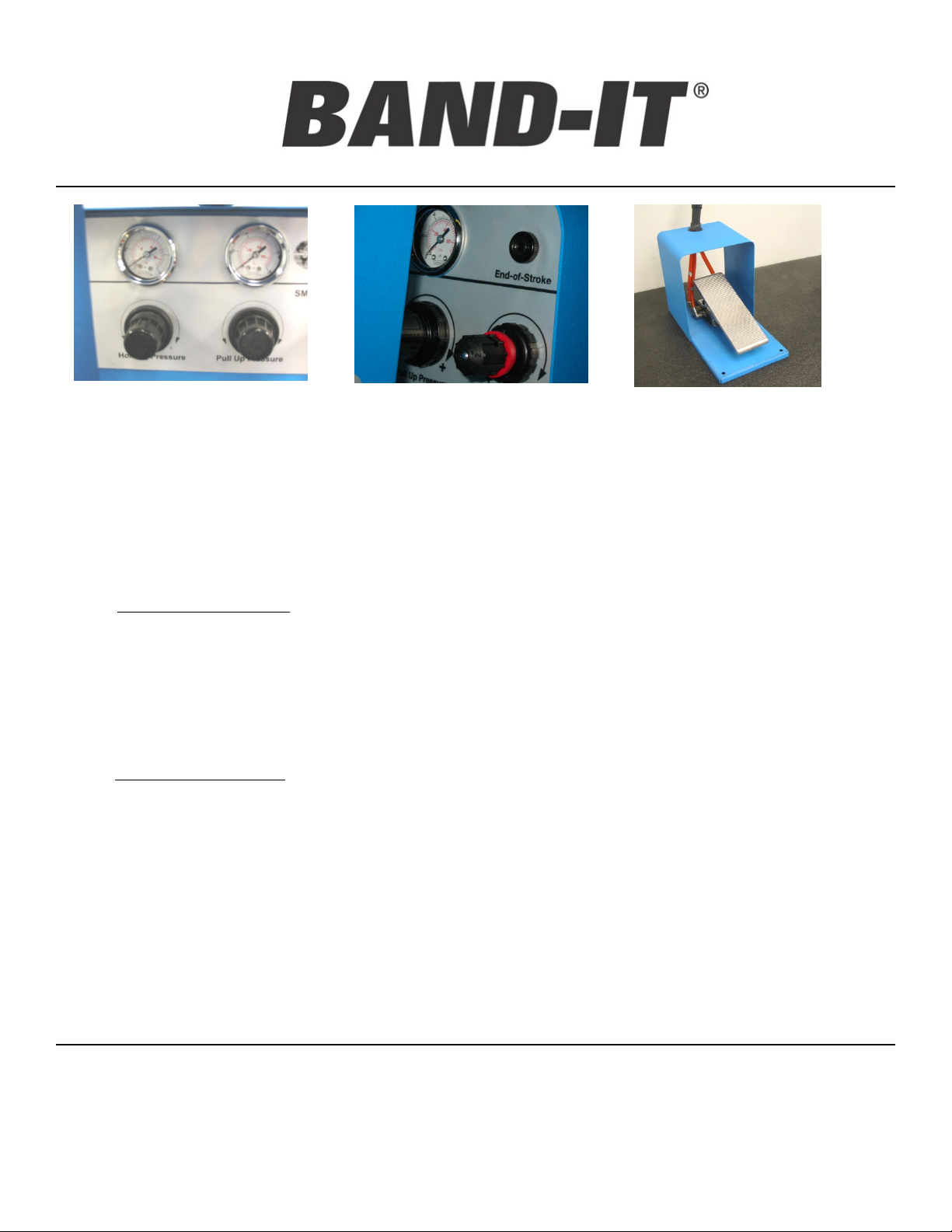
Air pressure setting can be
made using the regulators and
gauges on face of the tool.
Rule: Always approach pull-up pressure setting from below and hold pressure setting from above the
recommended value.
End-of-Stroke Indicates the
desired clamp tension and cut-off
has not occurred. Also shown is
speed control with red lock ring.
Dual function foot control valve.
Pressing forward activates
clamp installation. Heel action
activates tail return and
prepares for next clamp.
1. Set the speed control to blue for all BAND-IT 5/8” wide Center Punch Clamps.
2. Set pull-up pressure: pull knob and turn clockwise to reach pull-up pressure. Approach
pressure setting from below by increasing pressure. Suggested settings are listed below.
Adjust as necessary for the clamping application. Caution! Do not adjust below 20 psi or
head misfires may occur.
35 PSI for 5/8” wide GCS clamps
40 PSI for 5/8” wide SS clamps
3. Set holding pressure to 8 – 12 PSI. With foot pedal at rest, increase pressure until it is above
recommended setting. Slowly lower pressure by turning knob counterclockwise to
recommended setting.
4. Check pressure setting by cycling tool until holding pressure gauge stops.
5. With foot pedal still depressed, verify all settings and adjust if necessary.
6. Reset tool by depressing heel end of foot pedal. Remove foot.
7. Repeat steps 2, 3, 4, and 5. At pressure kick down, verify all settings and adjust if necessary.
Caution: Always allow air to completely exhaust after resetting tool and before pull-up. Failure to
let air completely exhaust may result in clamps not pulling up tight.
BAND-IT-IDEX, Inc.
A Unit of IDEX Corporation
4799 Dahlia Street Denver, CO 80216-3070 USA
P: 1-800-525-0758 F: 1-800-624-3925
www.BAND-IT-IDEX.com
5
Document# SM1750 Rev. E
© Copyright
BAND-IT-IDEX, Inc. 2012
All rights reserved
Page 6
SM1700
Installing
Clamps
Pneumatic
Center Punch
Tool
Installing BAND-IT Center Punch Clamps:
1) Choose correct material type and diameter clamp to best satisfy the needs of the application.
2) Installation of two BAND-IT Center Punch Clamps per hose end is suggested. Place clamps over hose, then
install fitting. Note the location of the fitting’s hose barbs in order to locate clamps between barbs for maximum
fitting retention. The buckles of each clamp should be located opposite of each other to increase resistance to
leak paths.
3) Insert the clamp tail fully into the nose of the tool with the buckle on top. Position the clamp in the desired
location on hose.
4) Small diameter hose assemblies (less than approximately 2”) will receive a considerable impact during the lock
and clamp tail cut-off process. For stiff hoses, it will help to lessen the impact by holding these small hose
assemblies with only one hand on the hose end of the assembly (do not hold the end of the assembly with the
fitting). This will soften the jolt and allow the assembly to swing down to absorb the impact. For flat or thin-wall
hose, inserting an object that is soft and safe to hold into the end of the fitting for additional support may help.
Large diameter hose assemblies should be held securely with both hands.
Keep hands away from clamp being applied!
5) Depress the toe end of the foot pedal control to tension clamp, keep the toe end down until the clamp has been
fully tensioned, locked and cut-off is complete.
6) If the cylinder reaches the end of its stroke during tension, the cutoff cylinder will be disabled and the end-ofstroke indicator will turn red. Pull firmly on the clamp while reversing the cylinder. Remove the clamp. Before
regripping, cut off any tail greater than 4 inches. Start the tension cycle over at step 3.
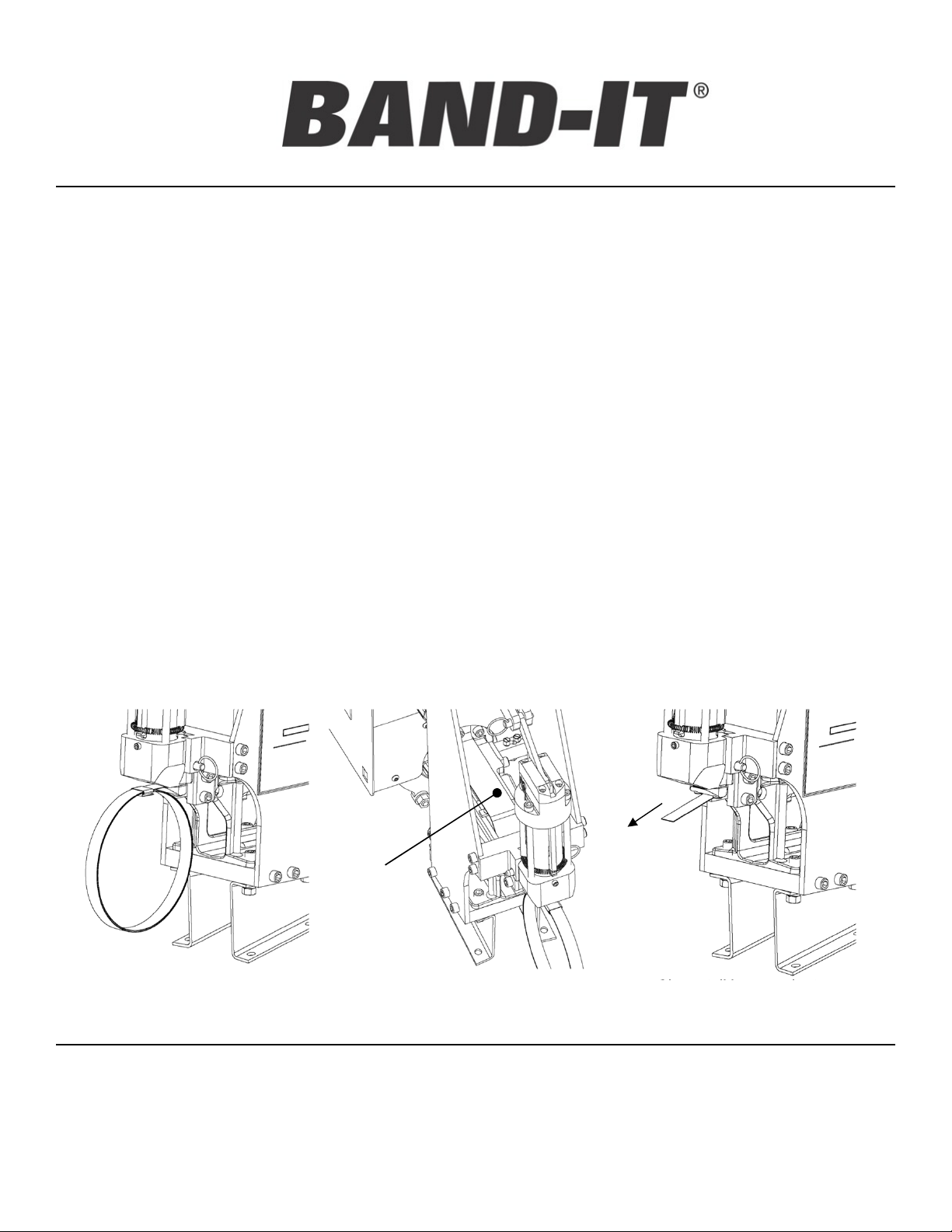
7) Depress the heel end of the foot control and retrieve the clamp tail from the tool head.
Clamp tail inserted into blade
assembly
Guard/tail depressor provides downward
pressure on scrap clamp tail.
Clamp tail in normal return
position. Pull tail from tool.
BAND-IT-IDEX, Inc.
A Unit of IDEX Corporation
4799 Dahlia Street Denver, CO 80216-3070 USA
P: 1-800-525-0758 F: 1-800-624-3925
www.BAND-IT-IDEX.com
6
Document# SM1750 Rev. E
© Copyright
BAND-IT-IDEX, Inc. 2012
All rights reserved
Page 7

SM1700
depressed and cylinder is returned for next
Trouble Shooting
Guide
Problem Probable Cause Correction
1. Sharp or scarred edges on clamp. Metal
deposits on underside of tail at buckle edge.
2. Tail is broken at approximately 45°. Clamp
material stretched or thinned at break.
3. Clamp tensions in a jerky manner.
4. Clamp pulls but does not lock.
5. Clamp tail slips in band gripper lever.
6. Clamp tail folded and caught inside tool Clamp tail catches as heel of f oot pedal is
7. Tool doesn't cut-of f clamp.
8. Tool takes excessive time for clamp
pull-up.
9. Clamp tail cannot be inserted into tool.
Loose or broken cutter blade / backing
plate.
Pull-up pressure set too high Reduce pull-up pressure. Apply clamp and
Clamp not inserted properly. Make sure clamp is straight and level w hen
Band gripper pin loose Tighten gripper pin set screw .
Pull-up cylinder needs lubrication Check filter / lubricator and add oil if
Loose cutter blade on head Check and tighten all hardw are.
Clamp tail is too long and the end of stroke
has been reached.
Center Punch head not connected after
previous maintenance.
Broken or w orn teeth on gripper
Pressure settings too high Settings are a guide, it may be necessary to
Gripper springs stretched out Replace springs.
Tripper plate stuck due to dirt or lack of
lubrication
clamp cycle.
Loose or broken cutter blade Tighten or replace cutter blade.
CP Head disconnected Connect CP Head ass embly.
Low pressure on incoming air supply Check and adjust incoming air supply. Note:
Air leak from loose connection or w orn
parts
Speed Control regulator set too low Adjust to Blue setting per instructions.
Previous clamp tail has not yet been
removed
Tripper plate may be broken or binding. Remove, inspect, clean and lubricate or
Make certain all fasteners are tight. Replace
any broken or chipped blades. Cutter Blade
and Backing each have a dual edge design
and can be rotated to unused side one time
before being replaced as a set.
adjust if necessary.
inserting.
necessary.
Reverse foot pedal and pull hose assembly
back to expose clamp tail. Cut of f excess
clamp tail and resume.
Connect cut-of f cylinder w ith provided quick
release pin assembly.
Replace gripper.
low er pressure settings.
Check and clean/or re-lubricate the tripper
plate.
1) Re-cycle tool 2) Operate the tool to bring the
piston to about half w ay. 3) To remove the
clamp tail, reach under piston rod and locate
band gripper lever. 4) Rotate lever tow ard
clamp head and allow tail to fall from tool. If tail
remains stuck, use pliers to grasp tail and
caref ully remove. Never position fingers
anywhere b ut on gripper lever!
Minimum supply pressure is 70 PSI.
Remove tool cover and tighten loose
connections and / or replace w orn parts.
Remove clamp tail from tool.
replace tripper plate.
Pneumatic
Center Punch
Tool
BAND-IT-IDEX, Inc.
A Unit of IDEX Corporation
4799 Dahlia Street Denver, CO 80216-3070 USA
P: 1-800-525-0758 F: 1-800-624-3925
www.BAND-IT-IDEX.com
7
Document# SM1750 Rev. E
© Copyright
BAND-IT-IDEX, Inc. 2012
All rights reserved
Page 8

SM1700
Preventative
Maintenance
Pneumatic
Center Punch
Tool
1. For best results and proper functioning of the SM1700 air tool, a filter / lubricator must be
used on the air supply or in line within 30 feet of the air tool. The warranty is voided if a
filter / lubricator is not used.
2. Before using air tool, check to see that the blade and backing plate on the CP head are fully
tensioned. Loose bolts can easily cause breakage of blade and backing plate.
3. Clean gripper occasionally. Particles and dirt on the gripper lever can cause it to slip off the
clamp tail. To remove gripper lever, loosen set screw in the head assembly from underneath
the block and tap out pin.
4. The BAND-IT SM1700 Air Tool, although durable, does need periodic maintenance and
repair. The frequency of significant repairs can be greatly reduced by simply following
regular preventative maintenance such as maintaining tension on fasteners, proper
lubrication and not “free cycling” the tool without tensioning clamps.
Preventative Maintenance Schedule
Frequency Component Check
Daily Tool and tool head Check for and tighten all fasteners.
Filter / Lubricator Check for build-up of dirt, etc. Check for contaminated or
discolored lubricant.
Check for low lubricant. Refill with DTE 24 hydraulic oil. Set
drip rate to 1 drop each 10-25 cycles.
Every 2,000 clamps Gripper Check for build-up of dirt, etc., in teeth. Remove and clean.
Replace as necessary with new gripper kit.
Every 5,000 clamps Cutter Blade and
Backing Plate
Every 10,000 clamps Tool Head Return head to BAND-IT for service.
Every 6 Months Cylinder Check for build-up of dirt, contaminants on piston rod seals.
Tripper Plate Check for build-up of dirt, contaminants, etc. Clean and
Air Exhaust Mufflers Check for build-up of dirt, contaminants, etc. Remove and
Rotate both parts. If parts have been rotated once before,
replace both as a kit.
Clean exterior with soap and warm water.
apply lubricant.
clean with non-flammable degreaser.
BAND-IT-IDEX, Inc.
A Unit of IDEX Corporation
4799 Dahlia Street Denver, CO 80216-3070 USA
P: 1-800-525-0758 F: 1-800-624-3925
www.BAND-IT-IDEX.com
8
Document# SM1750 Rev. E
© Copyright
BAND-IT-IDEX, Inc. 2012
All rights reserved
Page 9

SM1700
Center Punch
Head Information
Periodically check
mounting screws for
tightness.
Pneumatic
Center Punch
Tool
Important: Do not actuate
head unless installing a
clamp. If any visible
damage appears to head,
discontinue use and return
to BAND-IT®.
Backing Plate: Reversible,
5,000 clamps per side
Cutter Blade: Reversible,
CENTER PUNCH HEAD
(ENTIRE ASSY SHOWN)
REPLACEMENT PARTS LIST FOR THE HEAD
5,000 clamps per side
Mounting Screws:
Replace with kit
Part Number Qty Description Contents
M17799 1 Cutter Blade Kit Includes Blade, Backing plate,
Mounting screws, and Instructions
M17098 1 Center Punch Head Complete Head, Replacement
BAND-IT-IDEX, Inc.
A Unit of IDEX Corporation
4799 Dahlia Street Denver, CO 80216-3070 USA
P: 1-800-525-0758 F: 1-800-624-3925
www.BAND-IT-IDEX.com
9
Document# SM1750 Rev. E
© Copyright
BAND-IT-IDEX, Inc. 2012
All rights reserved
Page 10

SM1700
Gripper
Assembly
Pneumatic
Center Punch
Tool
•To remove gripper and/or tripper plate:
1. Unhook the 2 gripper springs
2. Bring the piston fully forward
3. Loosen the gripper pin set screw
4. Tap the gripper pin out
5. To remove tripper plate, move the piston
slightly back. Remove front plate, and slide
free
Gripper pin access hole
Gripper pin
Tripper plate
Clean and lubricate
periodically
Gripper pin set screw
Loosen to remove gripper pin
Gripper
Clean teeth periodically
REPLACEMENT PARTS LIST FOR THE GRIPPING SYSTEM
Gripper springs
Part Number Qty Description Contents
S45087 1 Tripper plate
S45199 1 Gripper Kit One Gripper and two Gripper springs
BAND-IT-IDEX, Inc.
A Unit of IDEX Corporation
4799 Dahlia Street Denver, CO 80216-3070 USA
P: 1-800-525-0758 F: 1-800-624-3925
www.BAND-IT-IDEX.com
10
Document# SM1750 Rev. E
© Copyright
BAND-IT-IDEX, Inc. 2012
All rights reserved
Page 11

SM1700
Replacement
Service Parts
Identification
Production tools will experience wear of specific parts. Preventative Maintenance, including
regular cleaning, lubrication and checking all fasteners for tension will reduce the replacement
frequency of these parts.
Pneumatic
Center Punch
Tool
Air Connections for
Supply to Cut-off
Cylinder
Quick Disconnect Pin
C P Head
Quick
Disconnect Pin
Cut-off Cylinder
Air
Pressure
Gauges (2)
End-ofStroke
Indicator
Air Pressure
Regulators (2)
Clamp Tension
Speed Control
Cutter Blade,
Cutter knife and
Gripper Assembly
BAND-IT-IDEX, Inc.
A Unit of IDEX Corporation
4799 Dahlia Street Denver, CO 80216-3070 USA
P: 1-800-525-0758 F: 1-800-624-3925
www.BAND-IT-IDEX.com
11
Tension Cylinder
Limit Switch
Caution! Do not disable
Serial Number Location
Document# SM1750 Rev. E
© Copyright
BAND-IT-IDEX, Inc. 2012
All rights reserved
Page 12

Replacement
Service Parts
Identification
ITEM PART NO. QTY DESCRIPTION ITEM PART NO. QTY DESCRIPTION
1 A09487 4 SCREW, CAP, 5/16-18 X 1.50 L 59 S31487 0.05 OIL, DTE 24 HYDRAULIC (QT)
2 A81587 13 TUBE, POLYURETHANE, 1/4 (FT) 60 S31 589 1 OIL AND BOTTLE, LUBRICATING
3 C00387 0.15 LOCKING COMPOUND, HIGH STRENGTH, RED (CC) 61 S32687 2 SCREW, CAP, 1/4-20 X 1.75 L
4 G00689 2 SWIVEL UNION, M X F 62 S32 787 2 NUT, HEX, 1/4-20
5 G92188 4 NUT, HEX, 5/16-18 63 S33 987 8 WASHER, FLAT, .341 ID X .690 OD
6 I20587 4 FITTING, SWIVEL, 1/8 BARB 64 S34187 4 WASHER, FLAT, .19 X .44 X .05
7 J60767 1 TUBE, CYLINDER 65 S34 287 6 LOCK WASHER, 3/8 ID
8 J61187 1 PIN, SPRING, .125D X 1.35L 66 s36887 3 ELBOW, MALE R.A, 1/4 NPT X 3/8 TUBE
9 J61967 1 PLATE, ROD GUIDE 67 S37 387 5 COUPLER, MALE, 1/4 NPT
10 J62187 6 CYLINDER BOLT 68 S37 487 2 TEE, STREET
11 J63187 1 O-RING, .734 ID X .139 69 S39 387 1 DECAL, DTE 24 REQUIREMENT
12 J63287 1 O-RING, 5.437 ID X .295 70 S39 787 0.25 SEALANT, GASKET AND JOINT (OZ)
13 J64887 1 SCREW, SET, #10-32 X .188 L 71 S42 387 1 PLUG, CAP, 1/4 NPT
14 J65487 1 SCREW, SET, 5/16-24 X .375 L 72 S 44287 1 PANEL, FRONT, SM1700
15 J66487 1 PIN, GRIPPER BACK-UP 73 S44687 1 PISTON, CYLINDER
16 J66587 4 LOCK WASHER, 5/16 ID 74 S44887 1 SPACER, .205 X .504
17 J66687 2 GASKET, CYLINDER 75 S44 987 1 BOLT, HEX, 1/2-13 X 2.5L
18 J67287 1 SCREW, CAP, 1/4-28 X .50 L 76 S45 087 1 PLATE, BAND GRIPPER
19 J67687 8 NUT, HEX, 3/8-24 77 S45 186 1 GRIPPER, BAND, FINISHED, REX
20 J68587 4 SCREW, CAP, #8-32 X .38 L 78 S45 287 1 ROD, CYLINDER, SM1700
21 J90987 17 SCREW, CAP, 5/ 16-18 X .88 L 79 S45587 1 O-RING, .487 ID X .103
22 M17090 1 HEAD, CP, AUTOMATIC 80 S45 687 1 WASHER, 17/32 X 1-1/16
23 M17188 1 DETENT PIN, QUICK RELEASE 81 S45 987 1 TOOL BASE, SM1700
24 M18887 1 PIN, DETENT. 5/16 D X 2.5 L 82 S46188 1 PANEL, REAR
25 M25087 1 DECAL, FRONT, SM1700 83 S46 288 1 PANEL, TOP COVER
26 M25187 1 BRACKET, BASE, SM1700 84 S46 587 3 HEX, #10-32 X 3/8-24 X 3/4" L
27 M25287 1 DOVETAIL, SM1700 85 S4668 7 1 HEX, #10-32 X 3/8-24 X 5/8" L
28 M25387 1 CLEVIS, CUTOFF, SM1700 86 S46787 1 ADAPTER, BULKHEAD
29 M25587 1 LEAF SPRING, SM1700 87 S46 888 1 GUARD, FOOT VALVE
30 M25687 2 PIVOT, CYLINDER, SM1700 88 S46987 2 BASE, INCLINED
31 M25787 2 BRACKET, SIDE, SM1700 89 S47 087 1 VALVE, FLOW CONTROL
32 M25887 1 CYLINDER, CUTOFF, SM1700 90 S47287 2 VALVE, 4-WAY, ASSY
33 M25987 1 SPEED CONTROL, MUFFLER, SM1700 91 S473 87 1 VALVE, FOOT
34 M26187 1 DECAL, SERIAL, SM170 0 92 S47487 1 REGULATOR, PULL UP
35 M26287 1 DECAL, SIDE, SM170 0 93 S4 7587 2 REGULATOR, HOLDING
36 M26387 2 COVER, SHIPPING BOX, SM1700 94 S47 687 1 GAUGE, PRESS, 0-100, 1/8 NPT
37 M26487 1 TUBE, SHIPPING BOX, SM1700 95 S47787 1 GAUGE, HOLDING
38 M26587 1 BASE, SHIPPING, SM1700 96 S47988 1 COVER, CYLINDER, REAR
39 M26887 1 VALVE, STROKE LIMIT 97 S48 187 1 NUT, HEX, 3/4-16
40 M26987 1 ACTUATOR, BALL, STROKE LIMIT 98 S48387 3 ELBOW, 90 DEG, STREET
41 M29187 1 INDICATOR, STROKE LIMIT 99 S48487 1 BUSHING, REDUCER
42 M29287 1 PLATE, VALVE, STROKE LIMIT 100 S 48687 1 FITTING, Q-R, STRAIGHT, 1/4 X 1/4NPT
43 M29387 1 PISTON STOP, SM1700 101 S48787 9 ELBOW, MALE, 90 DEG
44 M29687 2 DECAL, WARNING 102 S48887 2 CONNECTOR, 1/8 NPTF X 1/4 OD TUBE
45 M29987 1 FRONT PLATE, PISTON 103 S48987 2 ELBOW, MALE, 90 DEG
46 P00187 1 LABEL, BLANK, 3.5 X 1.85 104 S49287 3 RUN TEE, MALE
47 P70587 1 BAG, CLEAR PLASTIC 105 S49387 1 CLAMP, HOSE
48 R00608 3.5 TUBING, NYLON, 1/4 (FT) 106 S49987 2 VALVE, QUICK EXHAUST
49 R00631 4 BUMPER, SELF ADHESIVE 107 S50287 1 RING, PANEL MOUNT
50 S10487 4 SCREW, CAP, 5/16-18 X .63 L 108 S50687 1 LUBRICATOR
51 S11787 4 MUFFLER, AIR EXHAUST, 1/4 NPT 109 S 51787 1 GROMMET, HOSE
52 S15587 1 PLUG, NYLON, 1/4 110 S51987 1 HOSE ASSY. S750
53 S21587 1 PIN, GRIPPER PIVOT 111 S 52587 1 FILTER
54 S21877 1 HEAD, FRONT, CYLINDER 112 S 52687 2 SPRING, GRIPPER CLOSING
55 S25587 2 SEAL COMPOUND, TEFLON (CC) 113 S 67587 2 TEE, UNION, 1/4
56 S25787 0.01 LUBRICANT, MOLY PASTE (OZ) 114 S69587 10 SCREW, BUTTON HD, #10-32 X 3/8
57 S26387 2 WASHER, LOCK, 1/4 115 SM1750 1 INSTRUCTIONS, SM1700
58 S30587 2 LETTER, ADHESIVE (EACH) 116 T50587 1 MUFFLER, EXHAUST
SM1700
Pneumatic
Center Punch
Tool
BAND-IT-IDEX, Inc.
www.BAND-IT-IDEX.com
A Unit of IDEX Corporation
4799 Dahlia Street Denver, CO 80216-3070 USA
P: 1-800-525-0758 F: 1-800-624-3925
12
Document# SM1750 Rev. E
© Copyright
BAND-IT-IDEX, Inc. 2012
All rights reserved
Page 13

Replacement
Service Parts
Identification
SM1700
Pneumatic
Center Punch
Tool
BAND-IT-IDEX, Inc.
A Unit of IDEX Corporation
4799 Dahlia Street Denver, CO 80216-3070 USA
P: 1-800-525-0758 F: 1-800-624-3925
www.BAND-IT-IDEX.com
13
Document# SM1750 Rev. E
© Copyright
BAND-IT-IDEX, Inc. 2012
All rights reserved
Page 14

Replacement
Service Parts
Identification
SM1700
Pneumatic
Center Punch
Tool
BAND-IT-IDEX, Inc.
A Unit of IDEX Corporation
4799 Dahlia Street Denver, CO 80216-3070 USA
P: 1-800-525-0758 F: 1-800-624-3925
www.BAND-IT-IDEX.com
14
Document# SM1750 Rev. E
© Copyright
BAND-IT-IDEX, Inc. 2012
All rights reserved
Page 15

Replacement
Service Parts
Identification
SM1700
Pneumatic
Center Punch
Tool
BAND-IT-IDEX, Inc.
A Unit of IDEX Corporation
4799 Dahlia Street Denver, CO 80216-3070 USA
P: 1-800-525-0758 F: 1-800-624-3925
www.BAND-IT-IDEX.com
15
Document# SM1750 Rev. E
© Copyright
BAND-IT-IDEX, Inc. 2012
All rights reserved
Page 16

Replacement
Service Parts
Identification
SM1700
Pneumatic
Center Punch
Tool
BAND-IT-IDEX, Inc.
A Unit of IDEX Corporation
4799 Dahlia Street Denver, CO 80216-3070 USA
P: 1-800-525-0758 F: 1-800-624-3925
www.BAND-IT-IDEX.com
16
Document# SM1750 Rev. E
© Copyright
BAND-IT-IDEX, Inc. 2012
All rights reserved
Page 17

SM1700
(INCHES)
Air Connection
Diagram
Pneumatic
Center Punch
Tool
Internal tubes are made of bulk part numbers. See chart below. When ordering individual
replacement tubes, specify tool part number (SM1700), tube part number, tube I.D. letter and
tube length.
LENGTH
TYPE
A 3/8 NYLON
N/A
B 3/8 NYLON
C 1/4 NYLON
D 8 1/4 NYLON
E 7.5 1/4 POLYURETHANE
F 6.5 1/4 POLYURETHANE
G 9 1/4 POLYURETHANE
H 6.5 1/4 POLYURETHANE
I 8 1/4 NYLON
J 2 1/4 POLYURETHANE
K 6 1/4 POLYURETHANE
L 8 .5 1 /4 NYLON
M 15 1/4 NYLON
N 13 1/4 POLYURETHANE
O 10 1/4 POLYURETHANE
P 36 1/4 POLYURETHANE
Q 30 1/4 POLYURETHANE
R 3 1/4 POLYURETHANE
S 13 1/4 POLYURETHANE
T 8 1/4 POLYURETHANE
U 2 1/4 POLYURETHANE
BAND-IT-IDEX, Inc.
A Unit of IDEX Corporation
4799 Dahlia Street Denver, CO 80216-3070 USA
P: 1-800-525-0758 F: 1-800-624-3925
www.BAND-IT-IDEX.com
17
Document# SM1750 Rev. E
© Copyright
BAND-IT-IDEX, Inc. 2012
All rights reserved
Page 18

SM1700
Factory Services
Pneumatic
Center Punch
Additional Factory Support and Tool Service:
Factory Service is Available
Users of the SM1700 should have years of dependable production if the preventative
maintenance procedures are followed as outlined in this manual. In addition to available
service parts, BAND-IT has additional factory service available. Service charges in
addition to parts replacement charges will be invoiced if tool is not covered by our
warranty. Please visit our website for our warranty information.
www.BAND-IT-IDEX.com/Warranty.html
Tool
Tool Service Information
1. If applicable, test and inspect tool to determine source of problem.
2. Totally dismantle tool and clean all parts.
3. Refinish external parts such as castings, cylinder, etc.
4. Inspect all parts for wear and damage. Replace as needed*.
5. Replace all expendable parts* such as gaskets, O-rings.
6. Reassemble, adjust, test, and inspect.
7. Clean exterior of tool.
*Parts replaced are invoiced at current parts prices.
BAND-IT-IDEX, Inc.
A Unit of IDEX Corporation
www.BAND-IT-IDEX.com
Document# SM1750 Rev. E
© Copyright
4799 Dahlia Street Denver, CO 80216-3070 USA
P: 1-800-525-0758 F: 1-800-624-3925
18
BAND-IT-IDEX, Inc. 2012
All rights reserved
 Loading...