

Page 1
Operating Manual
Shield-Lok™ SL4099 Tool Pack
an
d
Shield-Lok™ Clamp
Manual
SL4099 Shield-Lok™
Shield-Lok
™ Tool Pack
Clamp
BAND-IT-IDEX, Inc.
A Unit of IDEX Corporation
4799 Dahlia Street
Denver, CO 80216-3070 USA
P: 1-800-525-0758
F: 1-800-624-3925
www.BAND-IT-IDEX.com
Page 1
Document # P07687 Rev. E
© Copyright
BAND-IT-IDEX, Inc. 2012
All rights reserved
Page 2

Operating Manual
SL4099 Shield-Lok™
Shield-Lok
™ Tool Pack
Clamp
BAND-IT-IDEX, Inc.
A Unit of IDEX Corporation
4799 Dahlia Street
Denver, CO 80216-3070 USA
P: 1-800-525-0758
F: 1-800-624-3925
Page Intentionally Left Blank
www.BAND-IT-IDEX.com
Page 2
Document # P07687 Rev. E
© Copyright
BAND-IT-IDEX, Inc. 2012
All rights reserved
Page 3
Operating Manual
Table of Contents
SL4099 Shield-Lok™
Shield-Lok
™ Tool Pack
Clamp
Topic
P
age Description
Page #
Table of Contents 3
Safety Safety Guidelines / Warranty 4
Tool Pack Contents 5
Tool Overview 6
Specifications
Tool Specifications and Dimensions 7
Clamp Description 8
Clamp Installation 9 – 11
Operation
Lock Inspection 12
Maintenance Tool Maintenance 13 - 14
Troubleshooting Troubleshooting Guide 15
CE EC Declaration of Conformity 16
BAND-IT-IDEX, Inc.
A Unit of IDEX Corporation
4799 Dahlia Street
Denver, CO 80216-3070 USA
P: 1-800-525-0758
F: 1-800-624-3925
www.BAND-IT-IDEX.com
Page 3
Document # P07687 Rev. E
© Copyright
BAND-IT-IDEX, Inc. 2012
All rights reserved
Page 4

Operating Manual
SL4099 Shield-Lok™
Shield-Lok
™ Tool Pack
Clamp
Safety Guidelines and Warranty
R
ead this manual to help you understand the intent and operation of this tool prior to the
installation of Shield-Lok™ clamps.
o This product manual contains detailed instructions for setting-up the tool and safely
installing BAND-IT Shield-Lok™ clamps.
o Always wear safety glasses and appropriate gloves when operating this tool.
o Keep hands away from moving parts while installing clamps.
o Care should be taken to ensure fingers are not in the way of the clamp being applied.
o Always remove battery before performing maintenance.
IMPORTANT:
o T
he object clamped and the ½” Shield-Lok™ clamp must be compatible with each other
and with the environment in which the final product will be used.
The SL4000 tool is designed for use with BAND-IT ½” Sh
ield-Lok™ clamps only. Accordingly,
BAND–IT– IDEX, Inc. makes no representations with respect to the compatibility of these tools
when used with non-BAND-IT clamps.
Warranty:
For warranty information, or to view up-to-date literature and manuals go online at:
www.band-it-idex.com
BAND-IT-IDEX, Inc.
A Unit of IDEX Corporation
4799 Dahlia Street
Denver, CO 80216-3070 USA
P: 1-800-525-0758
F: 1-800-624-3925
www.BAND-IT-IDEX.com
Page 4
Document # P07687 Rev. E
© Copyright
BAND-IT-IDEX, Inc. 2012
All rights reserved
Page 5
Operating Manual
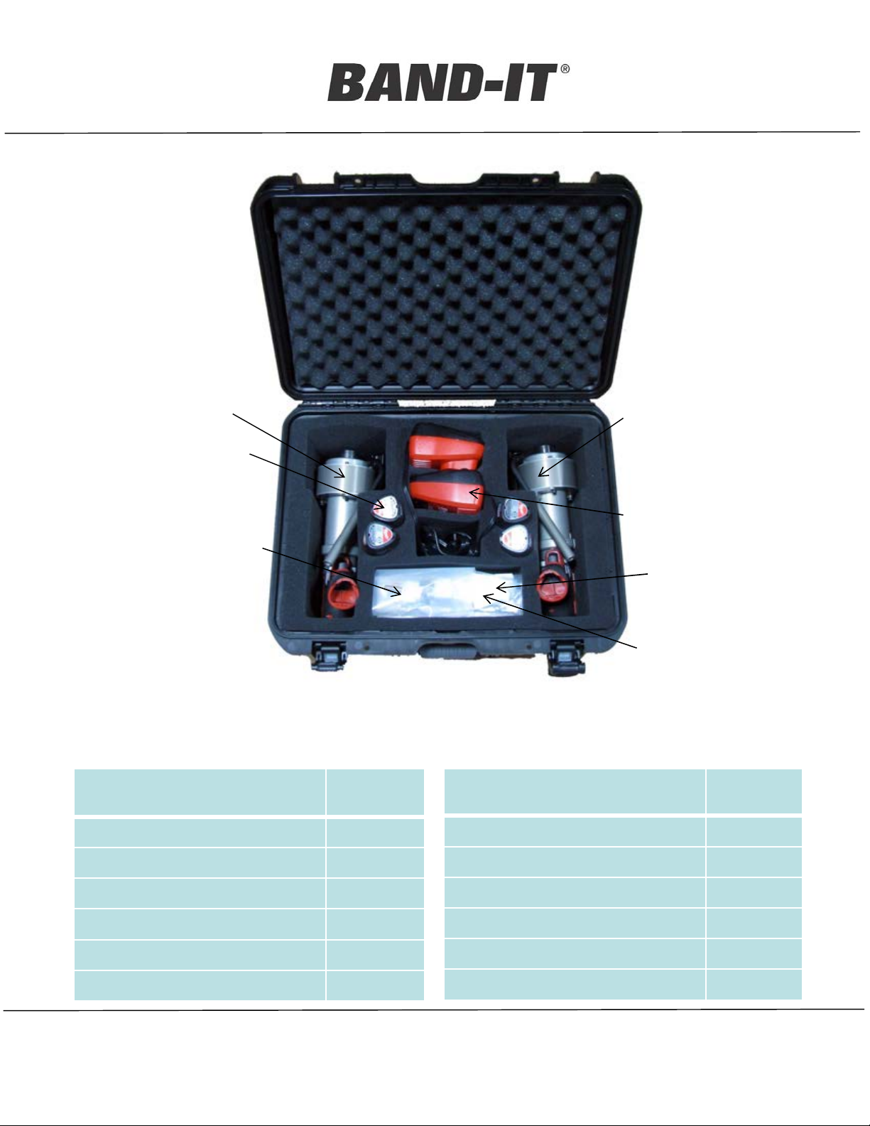
Tool Pack Contents
SL4099 Shield-Lok™
Shield-Lok
™ Tool Pack
Clamp
SL4000-1
BATTERIES
COIL PINS,
PUNCH
Note:
remove batteries from tool during shipping
Component name Q
uantity
SL4000-2
B
ATTERY
CHARGERS
SHEAR PLATES,
SCREWS
HEX KEYS
Component name Q
uantity
Case with Foam 1
SL 4000-1, SL Tool Left 1
SL 4000-2, SL Tool Right 1
Batteries 4
Battery Chargers 2
Hex key 3mm 1
BAND-IT-IDEX, Inc.
A Unit of IDEX Corporation
4799 Dahlia Street
Denver, CO 80216-3070 USA
P: 1-800-525-0758
F: 1-800-624-3925
Hex key 2.0mm 1
Shear plate 4
Screw, flat head, M3 4
Manual 1
Punch, 1/8” 1
1/8” x 5/8” HD, coiled pin 6
www.BAND-IT-IDEX.com
Page 5
Document # P07687 Rev. E
© Copyright
BAND-IT-IDEX, Inc. 2012
All rights reserved
Page 6

Operating Manual
SL4000 Tool Overview
G
1.
Lever
Cut Off Head
(Left-hand tool shown)
ear Release
Lanyard
A
ttachment
SL4099 Shield-Lok™
Shield-Lok
™ Tool Pack
Clamp
Drill Position
Assembly
Quick Release
Drill Speed
Control Switch
Cut Off
Handl
e
NOTES:
1.
Do not release gear system under
tension – may damage gear system.
BAND-IT-IDEX, Inc.
A Unit of IDEX Corporation
4799 Dahlia Street
Denver, CO 80216-3070 USA
P: 1-800-525-0758
F: 1-800-624-3925
www.BAND-IT-IDEX.com
Page 6
Battery
Document # P07687 Rev. E
© Copyright
BAND-IT-IDEX, Inc. 2012
All rights reserved
Page 7

Operating Manual
SL4000 Tool
Sp
ecifications
SL4099 Shield-Lok™
Shield-Lok
™ Tool Pack
Clamp
Clamp Type B
AND-IT ½” Shield-Lok™ Clamps
Powered Drill, Milwaukee, model 2410
Voltage 12VDC Battery
Cut Off Manually Activated Lever
Tension System Winding Mandrel, Gear Reduction System, Torque Limiter
Weight 4.1 Kg (9 Lbs)
Battery Charger Milwaukee, 12VDC output, 120VAC 60Hz input
Left-hand tool shown
BAND-IT-IDEX, Inc.
A Unit of IDEX Corporation
4799 Dahlia Street
Denver, CO 80216-3070 USA
P: 1-800-525-0758
F: 1-800-624-3925
www.BAND-IT-IDEX.com
Page 7
Document # P07687 Rev. E
© Copyright
BAND-IT-IDEX, Inc. 2012
All rights reserved
Page 8

Operating Manual
Clamp Description
Bu
ckle
SL4099 Shield-Lok™
Shield-Lok
™ Tool Pack
Clamp
Guard
Band
G
uard
Band
Shield
Tube
Buckle
Installed Clamp
BAND-IT-IDEX, Inc.
A Unit of IDEX Corporation
4799 Dahlia Street
Denver, CO 80216-3070 USA
P: 1-800-525-0758
F: 1-800-624-3925
www.BAND-IT-IDEX.com
Page 8
Document # P07687 Rev. E
© Copyright
BAND-IT-IDEX, Inc. 2012
All rights reserved
Page 9

Operating Manual
1
) Wrap band around tube and shield with
the shield and clamp guard aligned with
the buckle toward the operator. Insert the
end of the band through buckle, pull tight
and bend clamp tail away from buckle.
Clamp Installation
SL4099 Shield-Lok™
Shield-Lok
™ Tool Pack
Clamp
2) Align slot in winding mandrel
with slot in cut-off head and
insert band. Allow some band
between tool and tube.
3) Actuate drill until clutch begins to ratchet.
Allow tool to pull up the band freely, do not try to
guide the tool during pull up. Determine if clamp
is tight. If the clamp is not tight, lightly re-trigger
the drill a few times quickly to re-engage clutch,
and tighten.
BAND-IT-IDEX, Inc.
A Unit of IDEX Corporation
4799 Dahlia Street
Denver, CO 80216-3070 USA
P: 1-800-525-0758
F: 1-800-624-3925
www.BAND-IT-IDEX.com
Page 9
4) Push handle down and forward to
lock clamp to tubing and shield, and to
cut tail of clamp. Do not try to pull
the handle sideways. It will break the
coil pin
Document # P07687 Rev. E
© Copyright
BAND-IT-IDEX, Inc. 2012
All rights reserved
Page 10

Operating Manual
Buc
kle orientation with respect to cut-off head during clamp installation
Top of buckle
Locking arm
Blade
SL4099 Shield-Lok™
Shield-Lok
™ Tool Pack
Clamp
Locking arm of blade must fit into buckle opening between layers of
band
B
lade
Locking arm
BAND-IT-IDEX, Inc.
A Unit of IDEX Corporation
4799 Dahlia Street
Denver, CO 80216-3070 USA
P: 1-800-525-0758
F: 1-800-624-3925
Top of buckle
www.BAND-IT-IDEX.com
Page 10
Document # P07687 Rev. E
© Copyright
BAND-IT-IDEX, Inc. 2012
All rights reserved
Page 11

Operating Manual
Incorrect buckle position
SL4099 Shield-Lok™
Shield-Lok
™ Tool Pack
Clamp
Clamp inserted upside
down with respect to tool –
buckle will not seat to tool
Note: locking arm on
outside of band, not
between layers
BAND-IT-IDEX, Inc.
A Unit of IDEX Corporation
4799 Dahlia Street
Denver, CO 80216-3070 USA
P: 1-800-525-0758
F: 1-800-624-3925
www.BAND-IT-IDEX.com
Page 11
T
ool will not tighten clamp
and may not be able to cut
band
Document # P07687 Rev. E
BAND-IT-IDEX, Inc. 2012
All rights reserved
© Copyright
Page 12

Operating Manual
Section View
Good Clamp
Clamp and Lock Inspection
After clamp is applied
1
) Verify clamp is tight on tube and shield
2) Inspect lock on clamp
Inspect buckle on completed clamp
Lock sheared in center
and formed inside
shroud
Completed Free-End Clamp
SL4099 Shield-Lok™
Shield-Lok
™ Tool Pack
Clamp
F
RONT VIEW
(
Visually inspect lock)
Buckle Shroud
Section View
Bad Clamp
L
ock has slipped back
under sheared buckle
surface
Important: V
the buckle, remove clamp.
-
Hood position may vary between clamps
-It is allowable to pound hood down after
isually inspect lock formed into band as shown. If lock has slipped under the sheared surface of
SIDE VIEW
Completed Clamp
installation of clamp
Shear Surface
BAND-IT-IDEX, Inc.
A Unit of IDEX Corporation
4799 Dahlia Street
Denver, CO 80216-3070 USA
P: 1-800-525-0758
F: 1-800-624-3925
www.BAND-IT-IDEX.com
Page 12
Document # P07687 Rev. E
© Copyright
BAND-IT-IDEX, Inc. 2012
All rights reserved
Page 13

Operating Manual
S
hear plate
SL4000 Maintenance
Blade
SL4099 Shield-Lok™
Shield-Lok
™ Tool Pack
Clamp
3mm screws
Cut off head
6mm screws
Shear Plate Service
•
Remove battery from tool
• Remove shoulder bolts from cut-off head
Shims
4mm screw
and washer
• Remove 4mm screw washer and shims
• Gently pry blade away from cut-off head
• Remove screws from shear plate (SC052)
• Rotate or replace shear plate as needed (SC013)
• Re-assemble tool
I
tem Part Number Quantity Description
1 SC013 1 Shear Plate
2 SC052 2 Screw, Flat Head, M3 X 0.5 X 10
BAND-IT-IDEX, Inc.
A Unit of IDEX Corporation
4799 Dahlia Street
Denver, CO 80216-3070 USA
P: 1-800-525-0758
F: 1-800-624-3925
REPLACEMENT SERVICE PARTS
www.BAND-IT-IDEX.com
Page 13
Document # P07687 Rev. E
© Copyright
BAND-IT-IDEX, Inc. 2012
All rights reserved
Page 14

Operating Manual
Broken coil
pi
n
Coil Pin Replacement
SL4099 Shield-Lok™
Shield-Lok
™ Tool Pack
Clamp
The coil pin is
des
igned to be the
weak link in the cutoff system - the coil
pin will break when
forced 90oto normal
direction of cut
- Using the 1/8”
punch, remove
broken coil pin pieces
from handle and cam
- Insert the handle
into the cam and
close handle to be
sure the handle is
installed correctly
- Use the 1/8” punch
to align holes in cam
and handle as shown
- Tap a new coil pin
into place (flush with
cam)
BAND-IT-IDEX, Inc.
A Unit of IDEX Corporation
4799 Dahlia Street
Denver, CO 80216-3070 USA
P: 1-800-525-0758
F: 1-800-624-3925
www.BAND-IT-IDEX.com
Page 14
Document # P07687 Rev. E
© Copyright
BAND-IT-IDEX, Inc. 2012
All rights reserved
Page 15

Operating Manual
Shield-Lok
Troubleshooting Guide
T
his tool is not to be adjusted or serviced by the user.
SL4099 Shield-Lok™
™ Tool Pack
Clamp
Observed
P
roblem
When activating
cut off handle,
band does not cut
Band breaks
before cut off
Lock does not
form under
buckle
Drill will not
reach required
torque
Clamp not tight
on tube and
shield
Possible Cause Solution
Tension not reached Return to BAND-IT for repair
Retrigger tool to break band, service shear plate
Shear plate dull
Rotate or replace shear plate (page 13)
Return to BAND-IT for repair
Excess band tension
Excess wear on blade Return to BAND-IT for repair
Dead battery Change battery
Clutch not fully engaged
Bad drill Return to BAND-IT for repair
Retrigger tool to set clutch and continue to tighten
clamp
Winding mandrel
will not turn
when drill is
activated
Cut-off handle
loose
BAND-IT-IDEX, Inc.
A Unit of IDEX Corporation
4799 Dahlia Street
Denver, CO 80216-3070 USA
P: 1-800-525-0758
F: 1-800-624-3925
Gear release lever not in proper
location
Broken coil pin Replace coin pin per instructions (page 14)
www.BAND-IT-IDEX.com
Page 15
Check gear release lever on top of gearbox housing
Document # P07687 Rev. E
BAND-IT-IDEX, Inc. 2012
All rights reserved
© Copyright
 Loading...