

Page 1
Owner’s Manual
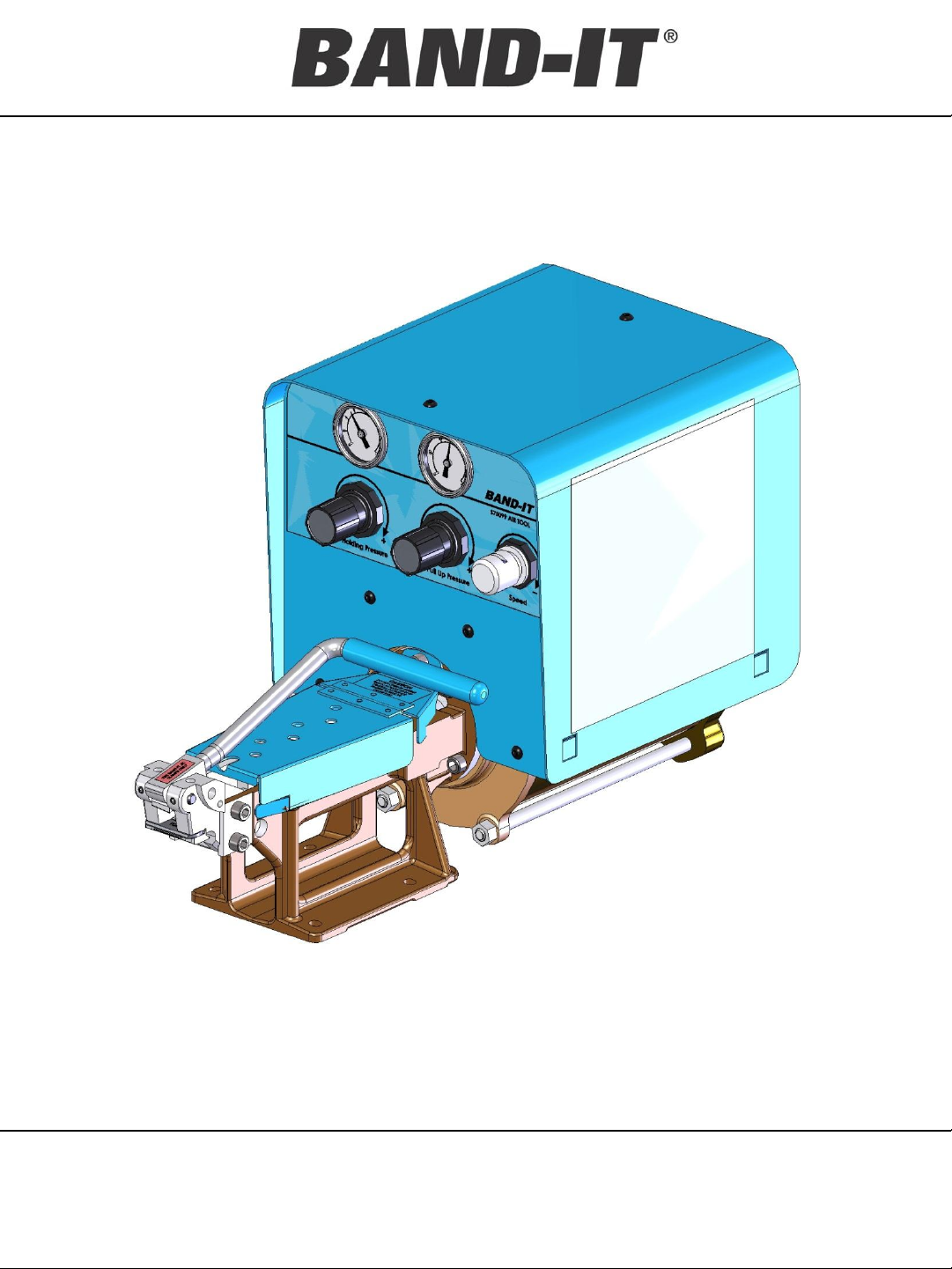
S75099 Pneumatic
and Tool Operating
Instructions
Junior Clamp
Application Tool
BAND-IT-IDEX, Inc.
A Unit of IDEX Corporation
4799 Dahlia Street Denver,
CO 80216-3070 USA
P: 1-800-525-0758 F: 1-800-624-3925
www.BAND-IT-IDEX.com
1
Document# P36687 Rev. I
© Copyright
BAND-IT-IDEX, Inc. 2013
All rights reserved
Page 2

Table of
Contents
S75099 Pneumatic
Junior Clamp
Application Tool
Page Information
2 Table of Contents
3 Warranty and Safety Guidelines
4 Tool Performance and Overview
5 Air System Requirements
6 Tool Installation and Precautions
7-8 Setting Controls and Tool Operation
9 Trouble Shooting Guide
10 Preventative Maintenance
11-16 Replacement Service Parts Identification
17 Installing Clamps
18-19 Replacement Service Parts
20 Optional Reference Gauge
21 Factory Services
BAND-IT-IDEX, Inc.
A Unit of IDEX Corporation
4799 Dahlia Street Denver,
CO 80216-3070 USA
P: 1-800-525-0758 F: 1-800-624-3925
www.BAND-IT-IDEX.com
2
Document# P36687 Rev. I
© Copyright
BAND-IT-IDEX, Inc. 2013
All rights reserved
Page 3

S75099 Pneumatic
Warranty
and Safety
For Warranty information visit the following URL
www.BAND-IT-IDEX.com/Warranty.html
Use of the S75099 without proper filtration and lubrication will void the warranty.
See section on air system requirements for details.
Safety Guidelines:
• Read this manual and become familiar with the tool before installing any clamps.
• Protective eyewear should be worn when connecting and disconnecting the tool to
compressed air sources and during operation.
Junior Clamp
Application Tool
• Wear appropriate gloves for handling steel while operating this tool, applying steel
clamps and removing the scrap clamp tail.
• Tool should be firmly mounted to an adequate support surface.
• Clamp tensioning or clamp tail retrieval can be immediately stopped by releasing
pressure from the foot pedal.
• When applying clamps, care should be taken to insure fingers and loose clothing are
not in contact with the clamp being applied.
• Never attempt to clamp objects which have the potential to burst, shatter or
otherwise cause bodily harm.
• Disconnect air supply prior to maintenance and disassembly of tool components.
• Liquids such as soaps and solvents should never be put directly into the airlines or
allowed to circulate through the tool.
• Additional Safety messages are included as part of the tool operation and clamp
installation sections.
BAND-IT-IDEX, Inc.
A Unit of IDEX Corporation
4799 Dahlia Street Denver,
CO 80216-3070 USA
P: 1-800-525-0758 F: 1-800-624-3925
www.BAND-IT-IDEX.com
3
Document# P36687 Rev. I
© Copyright
BAND-IT-IDEX, Inc. 2013
All rights reserved
Page 4

Tool Performance
S75099 Pneumatic
and Overview
Junior Clamp
Application Tool
• The S75099 has been designed to tension, set the Junior style lock and cut-off the
remaining scrap clamp tail of Junior Smooth I.D. and standard Junior preformed
clamps. BAND-IT manufactures Junior style clamps using galvanized carbon steel,
Type 201 Stainless Steel and Type 316 Stainless Steel. Clamp widths are available
from ¼” to ¾” wide and available diameter clamps range from 13/16” to as large as 8”.
All clamps can be easily installed on hose assemblies or objects chosen by the operator
using the BAND-IT S75099 air tool.
• During the operator controlled cycle, the S75099 Air Tool will tension the clamp around
the object by pulling the band through the buckle until the desired tension is achieved. If
the cycle is allowed to continue, the tool will release an amount of tension pressure
automatically, switching to a lower holding pressure. This pressure drop is in
preparation for manually setting the lock and shearing the excess clamp tail by
operating the cut-off handle*. The completion of each clamp includes setting the lock
while simultaneously cutting off the excess, scrap clamp tail. The finished lock should
be even with the height of the buckle thickness, have a smooth edge with no sharp
burrs while maintaining the low profile of the Junior style buckle.
*Important operational note! The S75099 tool directs compressed air through a foot
pedal control to cycle the tool and complete the installation of BAND-IT Junior style
clamps. The foot pedal has a dual action, forward (toe) and reverse (heel). During
normal operation, the operator should fully depress the foot pedal forward (toe), not
removing this pedal pressure until the cycle has completed, including the assembly roll
up and clamp tail cut-off. Upon completion of the lock, the heel of the foot pedal should
then be depressed causing the clamp tail to be positioned in the band slot, ready for
removal from the tool by the operator.
• Operating tip: Operation can be stopped at any time by removing the operators foot
completely from the foot pedal control, however, this will affect the tension applied to
the clamp. If cycle is ended prematurely, prior to hose assembly roll-up, depress the
heel side of the foot pedal to remove the hose assembly from the tool or momentarily
allow the air system to stabilize and resume the clamping cycle by pressing the foot
pedal control forward. If the roll-up cycle has already been initiated, re-tensioning the
clamp will result in the tail being overstressed and breaking prematurely before the lock
can be formed.
BAND-IT-IDEX, Inc.
A Unit of IDEX Corporation
4799 Dahlia Street Denver,
CO 80216-3070 USA
P: 1-800-525-0758 F: 1-800-624-3925
www.BAND-IT-IDEX.com
4
Document# P36687 Rev. I
© Copyright
BAND-IT-IDEX, Inc. 2013
All rights reserved
Page 5
S75099 Pneumatic
Air System
Requirements
Important: For proper tool performance, air requirements for S75099 should be:
Line Pressure – 100 psi minimum,125 psi maximum (689 – 862 kPa)
Volume - should be 3-5 CFM
Air Delivery system - ¼” minimum diameter airline with a ¼” N.P.T. connection.
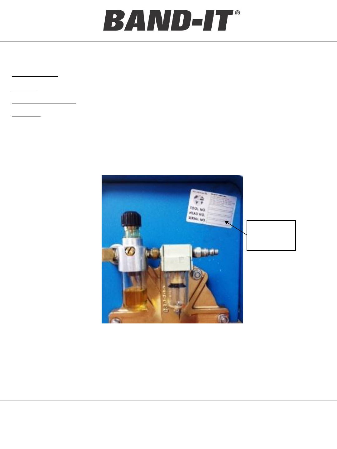
Filtration – Follow typical filtration requirements of air operated equipment. Standard filtering
systems should be located no further than 30’ from this tool in addition to the
supplemental system supplied at the back of the tool as shown below. This BAND-IT
supplied system includes a filter and lubricator. Lubricator should be refilled with DTE
24 hydraulic oil. The oil drip-rate can be verified by repeated full cycling the tool. One
drop should fall in the sight glass within 10-25 cycles. Excess oil will not benefit tool life
and may lead to blockage of air mufflers and a dirty environment.
Junior Clamp
Application Tool
Serial #
decal
location
View of the back side of the S75099 showing the
supplemental filtering and lubrication system as well as
the ¼” N.P.T. air connection with typical quick connect
coupling.
Warning: The lubricator should be refilled with DTE 24 hydraulic
oil only. The use of other oils may cause damage to the system.
BAND-IT-IDEX, Inc.
A Unit of IDEX Corporation
4799 Dahlia Street Denver,
CO 80216-3070 USA
P: 1-800-525-0758 F: 1-800-624-3925
www.BAND-IT-IDEX.com
5
Document# P36687 Rev. I
BAND-IT-IDEX, Inc. 2013
All rights reserved
© Copyright
Page 6

S75099 Pneumatic
Tool Installation
And Precautions
Tool Installation
1) Recommended work bench height is 34” – 40”. This height is suggested as the
optimum range for operator comfort and safety during typical clamp applications.
Locate and securely mount the tool on a solid surface making sure of ample
clearance on both left and right sides for handling hose assemblies of various
lengths.
2) The air tool should be firmly secured as close to the front edge of the work station
as possible using the angled mounting brackets supplied with the tool. This
position will reduce interference of hose assemblies during clamp application.
Mount the tool using 5/16” diameter fastening hardware (not supplied with tool).
Check hardware for tightness regularly.
3) Hardware may loosen during shipment. Loose fastening hardware will adversely
affect tool operation, specifically the cut off operation. All fasteners securing the
tool cover, pneumatics, head assembly, blade assembly, cut-off handle and
mounting hardware should be checked for tightness regularly and re-tensioned as
needed.
Junior Clamp
Application Tool
4) Use of the S75099 without properly maintained filtration and lubrication will cause
clamp tensioning problems and void the warranty.
Clamp Installation: Precautions
Operators should understand that a tighter clamp keeps the fitting more secure, but
excess tension could damage the hose assembly. The fitting stem must have prominent
barbs for proper retention inside the hose, but barbs must not be sharp to prevent cutting
into the hose. Hose, fitting and clamp must be compatible with each other and the
intended working environment. If in doubt, consult the hose or fitting manufacturer or call
BAND-IT.
Clamping objects other than hose require similar precautions.
CAUTION: Improperly tightened clamps may result in dangerous hose assemblies,
which could cause injuries or property damage.
CAUTION: Abuse or use of hose outside the manufacturers recommended conditions
may cause it to quickly deteriorate and become a safety hazard. This could result in
serious injury or property damage. Inspect and test hose assemblies frequently. Repair
or replace at the slightest sign of damage or deterioration.
BAND-IT-IDEX, Inc.
A Unit of IDEX Corporation
4799 Dahlia Street Denver,
CO 80216-3070 USA
P: 1-800-525-0758 F: 1-800-624-3925
www.BAND-IT-IDEX.com
6
Document# P36687 Rev. I
© Copyright
BAND-IT-IDEX, Inc. 2013
All rights reserved
Page 7
Setting Controls
S75099 Pneumatic
and Tool
Operation
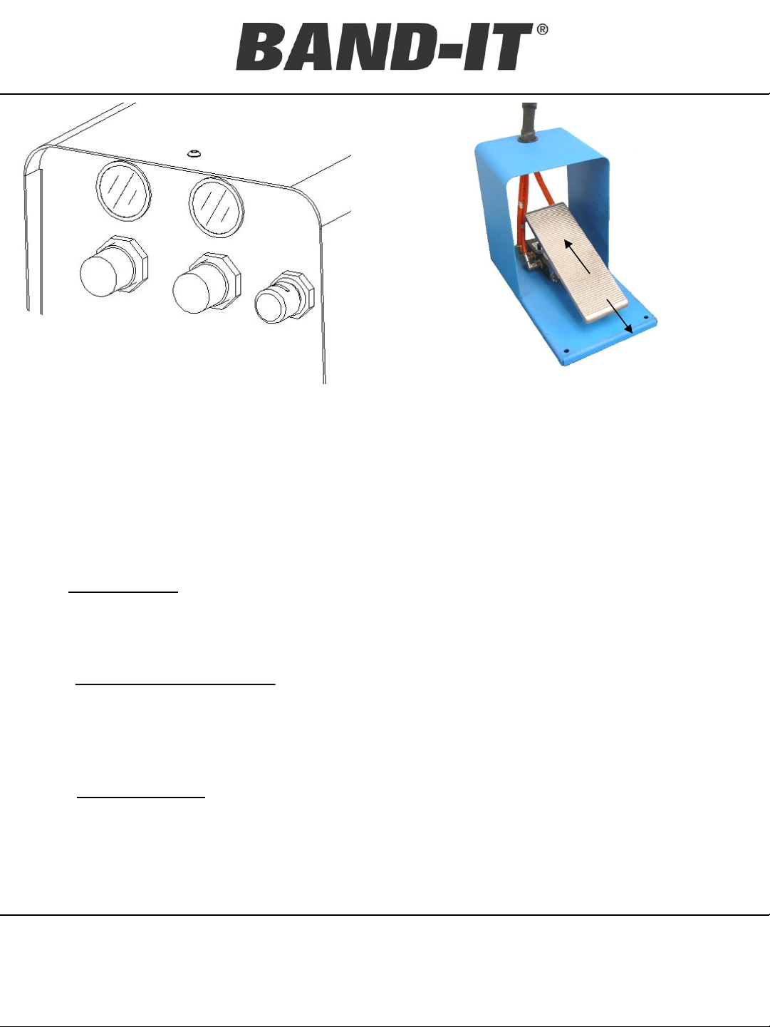
Air pressure setting can be made using the regulators
and gauges on face of the tool.
Junior Clamp
Application Tool
Dual function foot control valve. Pressing forward
activates clamp installation. Heel action activates tail
return and prepares for next clamp.
Rule: Always approach the pull-up pressure setting from below and the holding
pressure setting from above the recommended value.
Rule: Gauge readings are to be used as a guide. It may be necessary to adjust the
Pull-Up and Holding Pressure settings to match the requirements of the
particular hose assembly construction or application.
1. Speed Control adjusts the speed of piston travel during tensioning of the band clamp. A
slower setting will allow more time while a faster setting may cause increased friction
between the band and the buckle as the clamp tail is pulled through the buckle during
tensioning. Increased friction may cause the clamp to tension improperly.
2. Setting the Speed Control: The speed of the cycle should be set according to the width
of Junior Clamp being tensioned. Each width clamp has a color code setting on the
speed control regulator. See this manual page # 8 or the decal on the side of the tool.
Use the attached lock ring to secure the desired setting and prevent accidental
changes.
3. Pull-up Pressure reflects the tension applied to the clamp and is measured by force
applied to the clamp tail being pulled through the buckle. A pull-up pressure setting too
low may allow the fitting to be forced out of the hose assembly. A setting too high may
cause damage to the assembly or cause the clamp tail to tear. For most hose
applications, the ideal setting is as high as can be achieved without sacrificing the
strength of the lock, damaging the hose and fitting or breaking the clamp tail.
BAND-IT-IDEX, Inc.
A Unit of IDEX Corporation
4799 Dahlia Street Denver,
CO 80216-3070 USA
P: 1-800-525-0758 F: 1-800-624-3925
www.BAND-IT-IDEX.com
7
Document# P36687 Rev. I
© Copyright
BAND-IT-IDEX, Inc. 2013
All rights reserved
Page 8

Setting Controls
Clamp Width
Inch
Pull Up
Pressure
(PSI)
Holding
Pressure
(PSI)
Speed
Control
Setting
Pull Up
Pressure
(PSI)
Holding
Pressure
(PSI)
Speed
Control
Setting
Pull Up
Pressure
(PSI)
Holding
Pressure
(PSI)
Speed
Control
Setting
1/4" (6.4mm) 15 4 Blue 15 4 Blue NA NA NA
3/8" (7.5mm) 25 5 White 20 5 White 25 6 Blue
1/2" (12.7mm) 40 6 White 35 6 White 40 7 White
5/8" (15.9mm) 50 7 Red 40 7 Red 50 8 White
3/4" (19.1mm) 60 8 Red 50 8 Red 60 9 Red
Galvanized Carbon Steel
316 Stainless Steel
201 Stainless Steel
Guide for Operating Pressures for the S75099 Air tool
S75099 Pneumatic
and Tool
Operation
4. Setting Pull-up Pressure: Pull the identified regulator knob and turn clockwise to reach
Junior Clamp
Application Tool
pull-up pressure. Approach pressure setting from below by increasing pressure. Many
factors should be considered when choosing the correct operating setting for the tool.
The fitting design as well as the type, thickness and durometer of the hose material must
be considered when setting the correct pressures for your assembly.
5. Holding Pressure reflects a lower pressure designed to allow the hose assembly to be
rolled up in preparation for setting the lock with the shearing or cutting action on the clamp
tail. A setting too low will cause difficulty in shearing the clamp tail and leaving an
excessive burr on the buckle at the point of lock. A setting too high may cause the clamp
tail to “pop” free of the band gripper, cause the lock to slip back under the buckle or cause
a sudden jolt to the S75099 tool.
6. Setting Holding Pressure: Cycle the tool, holding the foot pedal in the toe forward position.
The tool will reach pull-up tension and kick down to a holding pressure. Read the gauge
and repeat the cycle turning the holding regulator clockwise to raise pressure or counter
clockwise to lower pressure. Allow the tool to settle after each cycle before reading the
value on the gauge.
7. Check pressure setting by cycling tool until hold pressure gauge stops.
8. Reset tool by depressing heel end of foot pedal. Remove foot.
9. Repeat steps 2, 4, 6, and 7. At pressure kick down, verify all settings and adjust if
necessary. Lock settings in place.
Rule: Allow air to completely exhaust between each stage of the tools cycle. Failure
to let air completely exhaust may result in clamps not pulling up tight.
BAND-IT-IDEX, Inc.
A Unit of IDEX Corporation
4799 Dahlia Street Denver,
CO 80216-3070 USA
P: 1-800-525-0758 F: 1-800-624-3925
www.BAND-IT-IDEX.com
8
Document# P36687 Rev. I
© Copyright
BAND-IT-IDEX, Inc. 2013
All rights reserved
Page 9

Problem Probable Cause Correction
Sharp or scarred edges on clamp. Metal
deposits on underside of tail at buckle
edge.
Loose or broken cutter blade /
backing plate. Sharp edge on cutter
blade due to wear
Remove and examine the cutterblade kit for
chips, cracks, excessive wear or material
build-up. Lightly hone with a medium grit India
stone to polish the leading surfaces. Alw ays
replace components as a kit, not individually.
Fully tighten included hardware.
Tail is broken at approximately 45°. Clamp
material stretched or thinned at break.
Pull-up pressure exceeds the
strength of the band clamp.
Reduce pull-up pressure to the suggested
range. Adjust lower if necessary.
Clamp not inserted properly. Insert clamp straight and level.
Pull-up cylinder needs lubrication Check filter / lubricator, fill to proper level.
Loose or worn cutter blade kit on
head
Check and tighten all hardware.
Teeth on band gripper lever are
chipped, filled with metal build up or
have excessive w ear
Remove and examine band gripper lever. Clean
or replace as necessary.
Pressure settings too high
Settings are a guide, it may be necessary to
lower pressure settings.
Gripper spring stretched out
Replace spring. Always replace gripper lever
and spring as a set.
Tripper plate stuck or broken Examine, clean and lube the tripper plate.
Clamp tail catches as heel of foot pedal is
depressed and cylinder is returned for
next clamp cycle.
Clamp tension or pull up pressure is
set low and has not yielded the band.
This may be necessary depending
upon the type of hose construction.
1) Re-cycle tool 2) Cycle tool keeping foot
control toe end depressed. 3) To remove
clamp tail, reach under piston rod and locate
band gripper lever. 4) Pull lever forward,
reaching under with pliers to grasp tail and
carefully remove tail. (Never position fingers
anywhere but on gripper lever, keep foot
control valve depressed forw ard while
working in this area).
Loose or broken cutter blade Tighten or replace cutter blade.
Low pressure on incoming air supply
Check and adjust incoming air supply. Note:
Minimum supply pressure is 75 PSI.
Air leaks from loose connection or
worn parts
Remove tool cover. Examine all air
connections, tighten loose connections and /
or replace worn parts.
Speed Control regulator set tool low
Adjust setting per instructions in this manual or
side panels decal.
Previous clamp tail has not been
Remove clamp tail from tool
Tripper plate may be broken or
binding.
Remove, inspect, clean and lubricate or
replace tripper plate.
Clamp pulls in a jerky manner.
Tool doesn't cut-off clamp.
Tool takes excessive time for clamp pullup.
Clamp tail cannot be inserted into tool.
Clamp tail slips in band gripper lever.
Trouble Shooting
Guide
S75099 Pneumatic
Junior Clamp
Application Tool
BAND-IT-IDEX, Inc.
A Unit of IDEX Corporation
4799 Dahlia Street Denver,
CO 80216-3070 USA
P: 1-800-525-0758 F: 1-800-624-3925
www.BAND-IT-IDEX.com
9
Document# P36687 Rev. I
© Copyright
BAND-IT-IDEX, Inc. 2013
All rights reserved
Page 10

S75099 Pneumatic
Component Check Action Frequency
Clamp Head
Check for loose mounting
screws
Tighten all screws and fasteners Daily
Shear hook
Check working edge for
wear or damage
replace if necessary (J00587). Daily
Cutter Blade and
Backing Plate
Check to see if blade is
loose or has any broken or
chipped edges
Tighten all screws and fasteners.
Replace if necessary (J93099).
Daily
Filter / Lubricator
Check for build-up of dirt,
etc. Check for low,
contaminated or discolored
lubricant
Drain and clean with soap and water.
Refill with hydraulic oil DTE 24. Set drip
rate to 1 drop each 10-25 cycles. Order
more lubricant if necessary (S31589).
Every 2,000
clamps
Gripper Lever
Check for build-up of dirt,
etc., in teeth and check
spring for tension.
Remove and clean with small pointed
object - knife blade, etc. Replace as
necessary with new gripper and new
spring as a kit (S45799).
Every 2,000
clamps
Cylinder
Check for build-up of dirt,
contaminants externally on
piston rod seals
Clean with soap and warm water 6 Months
Tripper Plate
Check for cracks, build-up
of dirt, contaminants
Clean and apply a light coating of moly
grease or equivalent
6 Months
Check for build-up of dirt,
contaminants, etc.
Remove and clean with non-flammable
degreaser
6 Months
Check for tight connection Tension as necessary 6 Months
Air Exhaust Mufflers
Maintenance Checklist
Preventative
Maintenance
Junior Clamp
Application Tool
1. For proper functioning of the S75099 air tool, a filter / lubricator must be used on the
air supply within 30 feet of the air tool. The warranty is voided if a filter / lubricator is
not used.
2. Before using air tool, check to see that the blade and backing plate are fully tensioned.
3. Clean gripper occasionally. Metal particles and dirt on the gripper lever can cause it to
slip off the clamp tail. To remove gripper lever, loosen set screw in the head assembly
from underneath the block and tap out pin.
BAND-IT-IDEX, Inc.
A Unit of IDEX Corporation
4799 Dahlia Street Denver,
CO 80216-3070 USA
P: 1-800-525-0758 F: 1-800-624-3925
www.BAND-IT-IDEX.com
10
Document# P36687 Rev. I
BAND-IT-IDEX, Inc. 2013
All rights reserved
© Copyright
Page 11

Replacement
S75099 Pneumatic
Service Parts
Identification
Junior Clamp
Application Tool
regular cleaning, lubrication and checking all fasteners for tension will reduce the replacement
frequency of these parts.
including new bolts.
Tension Air
Holding Air
Pressure
Gage
Pressure
Gage
Tension
Pressure
Regulator
Holding
Pressure
Regulator
Shear Hook
Cutter Blade,
Backing Plate, and
Gripper Assembly
BAND-IT-IDEX, Inc.
A Unit of IDEX Corporation
4799 Dahlia Street Denver,
CO 80216-3070 USA
P: 1-800-525-0758 F: 1-800-624-3925
www.BAND-IT-IDEX.com
11
Clamp
Tension
Speed
Control
Tension Cylinder
Cut-off
Handle
Document# P36687 Rev. I
© Copyright
BAND-IT-IDEX, Inc. 2013
All rights reserved
Page 12

Replacement
ITEM
PART
QTY
ITEM
PART
QTY
C00387
0.15 LOCKING COMPOUND, HIGH STRENGTH (CC)
S42387
PLUG, CAP, 1/4 NPT
G00689
SWIVEL UNION, M X F
S44687
PISTON, CYLINDER
G92188
NUT, HEX, 5/16
S44887
SPACER, .205 X .504
J60767
TUBE, CYLINDER
S44987
BOLT, HEX, 1/2
J61967
PLATE, ROD GUIDE
S45087
PLATE, BAND GRIPPER
J62187
CYLINDER BOLT
S45186
GRIPPER, BAND, FINISHED, REX
J63187
O
S45389
PISTON ROD ASSEMBLY
J63287
O
S45587
O
J64887
SCREW, SET, #10
S45687
WASHER, 17/32 X 1
J66587
LOCK WASHER, 5/16 ID
S45799
KIT, GRIPPER/SPRING
J66687
GASKET, CYLINDER
S45888
SLIDE COVER ASSEMBLY
J67687
NUT, HEX, 3/8
S46088
PANEL, FRONT, S750
J68587
SCREW, CAP, #8
S46188
PANEL, REAR
J90887
PIN, SHEAR HOOK PIVOT
S46288
PANEL, TOP COVER
J90987
SCREW, CAP, 5/16
S46587
HEX, #10
J93099
KIT, CUTTER BLADE
S46687
HEX, #10
P00187
LABEL, BLANK 1
S46787
ADAPTER, BULKHEAD
P06386
LABEL, FRONT, S750
S46888
GUARD, FOOT VALVE
P06486
DECAL, BAND
S46987
BASE, INCLINED
P06586
DECAL, PRESSURE, S750
S47087
VALVE, FLOW CONTROL
P36687
MANUAL,OPERATION S750 AIR TOOL
S47287
VALVE, 4
P70287
BAG, PLASTIC 4"X6"X.004
S47387
VALVE, FOOT
P70587
BAG, PLASTIC 10"X18"X.004
S47487
REGULATOR, PULL UP
R00608
TUBING, NYLON 1/4 OD X .180 ID (FT)
S47587
REGULATOR, HOLDING
R00631
BUMPER, SELF ADHESIVE
S47687
GAUGE, PRESS, 0
S10086
LINER, SHIPPING CARTON
S47787
GAUGE, HOLDING
S10087
PLYWOOD, BASE, AIR TOOL
S47988
COVER, CYLINDER, REAR
S10088
SHIPPING CARTON, AIR TOOL
S48187
NUT, HEX, 3/4
S11589
HANDLE ASSY, JR. HEAD
S48387
ELBOW, 90 DEG, STREET
S11787
MUFFLER, AIR EXHAUST, 1/4 NPT
S48487
BUSHING, REDUCER
S15587
PLUG, NYLON, 1/4
S48687
FITTING, Q
S18059
HEAD, JUNIOR CLAMP, ASSEMBLY
S48787
ELBOW, MALE, 90 DEG
S21587
PIN, GRIPPER PIVOT
S48887
CONNECTOR, 1/8 NPTF X 1/4 OD TUBE
S21789
TOOL BASE
S48987
ELBOW, MALE, 90 DEG
S21877
HEAD, FRONT, CYLINDER
S49287
RUN TEE, MALE
S25487
ELBOW, R.A STREET, 1/4 NPT
S49387
CLAMP, HOSE
S25587
COMPOUND, TEFLON, SEALANT (CC)
S49987
VALVE, QUICK EXHAUST
S25687
LOCKING COMPOUND MEDIUM STRGTH
S50287
RING, PANEL MOUNT
S25787
0.01 LUBRICANT, MOLY PASTE (OZ)
S50687
LUBRICATOR
S26387
WASHER, LOCK, 1/4
S50987
BOLT, CARRIAGE, 1/4
S30587
LETTER,ADHESIVE IDENTIFICATION
S51287
HEAD, JR AIR TOOL
S31487
0.05 OIL, DTE 24 HYDRAULIC (QT)
S51787
GROMMET, HOSE
S31589
OIL, LUBRICATION, & BOTTLE
S51987
HOSE ASSY, FOOT CONTROL S750
S31788
DECAL,
S52587
FILTER
S32687
SCREW, CAP, 1/4
S52987
PIN, CAM PIVOT
S32787
NUT, HEX, 1/4
S52687
SPRING, GRIPPER CLOSING
S34187
WASHER, FLAT, .19 X .44 X .05
S67587
TEE, UNION, 1/4
S34287
LOCK WASHER, 3/8 ID
S69587
SCREW, BUTTON HD, #10
S36887
ELBOW, MALE R.A, 1/4 NPT X 3/8 TUBE
S75091
INSERT, PACKAGING, S750 #1
S37387
COUPLER, MALE, 1/4 NPT
S75092
INSERT, PACKAGING, S750 #2
S37487
TEE, STREET
S75093
INSERT, PACKAGING, S750 #3
S39387
DECAL, DTE 24 REQUIREMENT
S76287
DECAL, CAUTION
S39787
0.25 COMPOUND,GASKET&JOINT SEALANT (OZ)
S75099 Pneumatic
Service Parts
Identification
NO.
NO.
1
2
3
4
5
6
7
8
9
10
11
12
13
14
15
16
17
18
19
20
21
22
23
24
25
26
27
28
29
30
31
32
33
34
35
36
37
38
39
40
41
42
43
44
45
46
47
48
49
50
51
52
53
8.5
0.5
1
4
1
1
6
1
1
1
4
2
8
4
1
14
1
1
1
1
1
1
1
1
4
1
1
1
1
3
1
1
1
1
1
1
2
6
2
1
1
2
6
4
6
3
3
2
1
DESCRIPTION
-18
-RING, .734 ID X .139
-RING, 5.437 ID X .295
-32 X .188 L
-24
-32 X .38 L
-18 X .88 L
-7/8" X 3-1/2"
-IT, LARGE
NAME PLATE
-20 X 1.75 L
-20
Junior Clamp
Application Tool
NO.
(CC) 91
100
101
102
103
104
105
NO.
54
55
56
57
58
59
60
61
62
63
64
65
66
67
68
69
70
71
72
73
74
75
76
77
78
79
80
81
82
83
84
85
86
87
88
89
90
92
93
94
95
96
97
98
99
1
1
1
1
1
1
1
1
-RING, .487 ID X .103
1
1
1
1
1
1
3
1
1
1
2
1
1
1
1
1
1
1
1
1
1
1
3
7
2
2
1
1
1
1
1
4
1
1
1
1
1
1
1
8
1
1
1
1
DESCRIPTION
-13 X 2.5L
-1/16
-32 X 3/8-24 X 3/4" L
-32 X 3/8-24 X 5/8" L
-WAY, ASSY
-100, 1/8 NPT
-16
-R, STRAIGHT, 1/4 X 1/4NPT
-20 X 1L
-32 X 3/8
BAND-IT-IDEX, Inc.
A Unit of IDEX Corporation
4799 Dahlia Street Denver,
CO 80216-3070 USA
www.BAND-IT-IDEX.com
P: 1-800-525-0758 F: 1-800-624-3925
12
Document# P36687 Rev. I
© Copyright
BAND-IT-IDEX, Inc. 2013
All rights reserved
Page 13

Replacement
S75099 Pneumatic
Service Parts
Identification
Junior Clamp
Application Tool
**
*
*See sheet 16 for additional part
numbers
**Insert S51987 hose assembly
through here using R00608 nylon
tubing.
BAND-IT-IDEX, Inc.
A Unit of IDEX Corporation
4799 Dahlia Street Denver,
CO 80216-3070 USA
P: 1-800-525-0758 F: 1-800-624-3925
www.BAND-IT-IDEX.com
13
Document# P36687 Rev. I
© Copyright
BAND-IT-IDEX, Inc. 2013
All rights reserved
Page 14

Replacement
S75099 Pneumatic
Service Parts
Identification
Junior Clamp
Application Tool
BAND-IT-IDEX, Inc.
A Unit of IDEX Corporation
4799 Dahlia Street Denver,
CO 80216-3070 USA
P: 1-800-525-0758 F: 1-800-624-3925
www.BAND-IT-IDEX.com
14
Document# P36687 Rev. I
© Copyright
BAND-IT-IDEX, Inc. 2013
All rights reserved
Page 15

Replacement
S75099 Pneumatic
Service Parts
Identification
Junior Clamp
Application Tool
BAND-IT-IDEX, Inc.
A Unit of IDEX Corporation
4799 Dahlia Street Denver,
CO 80216-3070 USA
P: 1-800-525-0758 F: 1-800-624-3925
www.BAND-IT-IDEX.com
15
Document# P36687 Rev. I
© Copyright
BAND-IT-IDEX, Inc. 2013
All rights reserved
Page 16

Replacement
S75099 Pneumatic
Service Parts
Identification
Junior Clamp
Application Tool
BAND-IT-IDEX, Inc.
A Unit of IDEX Corporation
4799 Dahlia Street Denver,
CO 80216-3070 USA
P: 1-800-525-0758 F: 1-800-624-3925
www.BAND-IT-IDEX.com
16
Document# P36687 Rev. I
© Copyright
BAND-IT-IDEX, Inc. 2013
All rights reserved
Page 17

S75099 Pneumatic
Installing
Clamps
Installing BAND-IT Junior and Junior Smooth I.D. Clamps:
1) Choose correct material type, band width and diameter clamp to best satisfy the
needs of the application. Adjust air pressure settings per S75099 tool
specifications per page 8.
2) Installation of two BAND-IT Junior style clamps per hose end is suggested.
Place clamps over hose, then install fitting. Note the location of the fitting’s hose
barbs in order to locate clamps between barbs for maximum fitting retention.
The buckle locations of each clamp should be applied opposite of each other to
increase resistance to leak paths.
3) Insert the clamp tail fully into the nose of the tool with the buckle on top.
Position the hose assembly inside the clamp in the desired location.
4) Depress the toe end of the foot pedal control to tension clamp, keeping the toe
end down until the clamp has been fully tensioned, locked and cut-off is
complete. Caution: If an oversized clamp is used on the assembly, the piston
may travel it’s full length and bottom out against the cylinder wall. The tool will
sense full pressure and switch to the lower Holding Pressure setting but clamp
will not be as tight as required! The clamp should be removed from the tool by
pressing the heel of the foot pedal and the operator will need to cut off excess
clamp tail, leaving 4” attached for inserting back into the tool head and taking
another grip of clamp tail. Cycle tool as explained above.
Junior Clamp
Application Tool
5) The clamp has now been fully tensioned and is ready to be completed. Allow
the tool to cycle into the cut-off mode and fully bleed off until holding pressure is
attained. Roll up the hose assembly to position the buckle under the Shear
Hook in the head assembly. Using a strong quick pulling action, pull the cut-off
handle which will cause the shear hook to generate a strong downward
pressure on the buckle. For a moment, just prior to the cut-off, the buckle will be
wedged between the shear hook and the backing plate at the mouth of the band
slot.
6) Depress the heel end of the foot pedal and retrieve the clamp tail from between
the cutter blade and shear plate.
Important advice and warning to user, read notes on page 6 before
applying clamps.
BAND-IT-IDEX, Inc.
A Unit of IDEX Corporation
4799 Dahlia Street Denver,
CO 80216-3070 USA
P: 1-800-525-0758 F: 1-800-624-3925
www.BAND-IT-IDEX.com
17
Document# P36687 Rev. I
BAND-IT-IDEX, Inc. 2013
© Copyright
All rights reserved
Page 18

Replacement
Service Parts
Installation Instructions for the J93099 Cutter Blade Kit
S75099 Pneumatic
Junior Clamp
Application Tool
*Components of this kit are a
dimensionally matched set. You may
have parts that look similar, but they
are different dimensionally. Parts
should be discarded and only new
matched sets should be used.
1. Remove old Cutter Blade Screws,
Cutter Blade and Backing Plate and
discard.
2. See illustrations to determine the
correct positions for correct component
assembly.
3. Hold Cutter Blade and Backing Plate
together, insert screws and tighten.
Installation Tip: This kit contains multiple sets
of screws with varying lengths. Choose the
correct length screw for your application.
Threads should protrude through the Cutter
Blade by less than ¼” .
Operating Tip: Keep the bolts tight. A loose
bolt may cause cracking or premature wear of
the Cutter Blade or Backing Plate. This could
result in improper clamp tensioning, locking
and cutting of excess clamp tail.
Operating Tip: Keep the leading edges of the
Cutter Blade and Backing Plate free of metal
shavings. Metal shavings will result in clamp
material gauging during tensioning. By hand,
DO NOT USE POWER TOOLS, clean and
hone the leading edges. Honing should polish
surfaces, not remove material.
BAND-IT-IDEX, Inc.
A Unit of IDEX Corporation
4799 Dahlia Street Denver,
CO 80216-3070 USA
P: 1-800-525-0758 F: 1-800-624-3925
www.BAND-IT-IDEX.com
18
Document# P36687 Rev. I
© Copyright
BAND-IT-IDEX, Inc. 2013
All rights reserved
Page 19

Replacement
Service Parts
S45799 Gripper and Spring Kit Installation Instructions
1. Extend the tool piston fully
forward. The gripper pin should
be visible through the access
hole.
S75099 Pneumatic
Junior Clamp
Application Tool
2. Disconnect air from the tool.
3. Loosen set screw and
disconnect gripper spring.
4. Tap out gripper pin, remove old
gripper and replace with new.
5. Connect new spring between
gripper and spring pin.
Shear Hook and Handle Assembly
To remove handle, loosen the
2 set screws and tap out pin.
Handle
Pin
S52987
Set
Screw
Gripper Pin
and Access
Hole
Gripper
Spring
Gripper
Cut-Off
Handle
S11589
Shear
Hook
J00587
BAND-IT-IDEX, Inc.
A Unit of IDEX Corporation
4799 Dahlia Street Denver,
CO 80216-3070 USA
P: 1-800-525-0758 F: 1-800-624-3925
www.BAND-IT-IDEX.com
Set
Screws
J64887
19
Shear
Hook Pin
J90887
Document# P36687 Rev. I
© Copyright
BAND-IT-IDEX, Inc. 2013
All rights reserved
Page 20

Optional
S75099 Pneumatic
Reference
Gauge
Remote Reference Gauge Kit
BAND-IT Part Number S67199
Union Tee
Remove Plug and
Insert Tube From
Air Gauge
Wood
Screws (3x)
Front Cylinder
Port
Remote Air
Gauge, 0-160 PSI
Tube From Union
Tee on Line “K”
Junior Clamp
Application Tool
Female
Connector
The Remote Reference Air Gauge will read air pressure in the front of the cylinder for both pull-up and holding
pressures. To read gauge: When tensioning a clamp, the maximum pressure the gauge reads during the cycle is
the pull-up pressure. After the tool switches over to the lower pressure holding cycle and before the clamp is
rolled up in preparation for lock, the pressure shown is the holding pressure.
For Tool with a Union Tee Installed at Line “K”:
1. Shut off air supply to tool. Completely bleed air tool system.
2. Remove plug from union tee. Connect the tube from the remote air gauge to the port the plug was
removed from.
3. Add sealant to the threads of the female connector and attach to the remote air gauge. Mount gauge in
desired location either using the 3 wood screws supplied or fasting hardware appropriate for the material
the gauge is to be mounted to.
For Tool without a Union Tee Installed at Line “K”:
1. Shut off air supply to tool. Completely bleed air tool system.
2. Cut tube line “K” 2 inches from front cylinder port. Insert supplied union tee between cut ends. Connect
the tube from the remote air gauge to the union tee.
3. Add sealant to the threads of the female connector and attach to the remote air gauge. Mount gauge in
desired location either using the 3 wood screws supplied or fasting hardware appropriate for the material
the gauge is to be mounted to.
BAND-IT-IDEX, Inc.
A Unit of IDEX Corporation
4799 Dahlia Street Denver,
CO 80216-3070 USA
P: 1-800-525-0758 F: 1-800-624-3925
www.BAND-IT-IDEX.com
20
Document# P36687 Rev. I
© Copyright
BAND-IT-IDEX, Inc. 2013
All rights reserved
Page 21

S75099 Pneumatic
Factory Services
Junior Clamp
Application Tool
Additional Factory Support and Tool Service:
repairs can be greatly reduced by following a simple, regular, preventative maintenance such
as maintaining tension on fasteners and proper lubrication as outlined in this manual. If this
tool needs repair or complete overhaul, it should be returned to BAND-IT in Denver.
charges in addition to parts replacement charges will be invoiced if tool is not covered by our
warranty. Please visit our website for our warranty information.
BAND-IT-IDEX, Inc.
A Unit of IDEX Corporation
4799 Dahlia Street Denver,
CO 80216-3070 USA
P: 1-800-525-0758 F: 1-800-624-3925
www.BAND-IT-IDEX.com
21
Document# P36687 Rev. I
© Copyright
BAND-IT-IDEX, Inc. 2013
All rights reserved
 Loading...