

Page 1
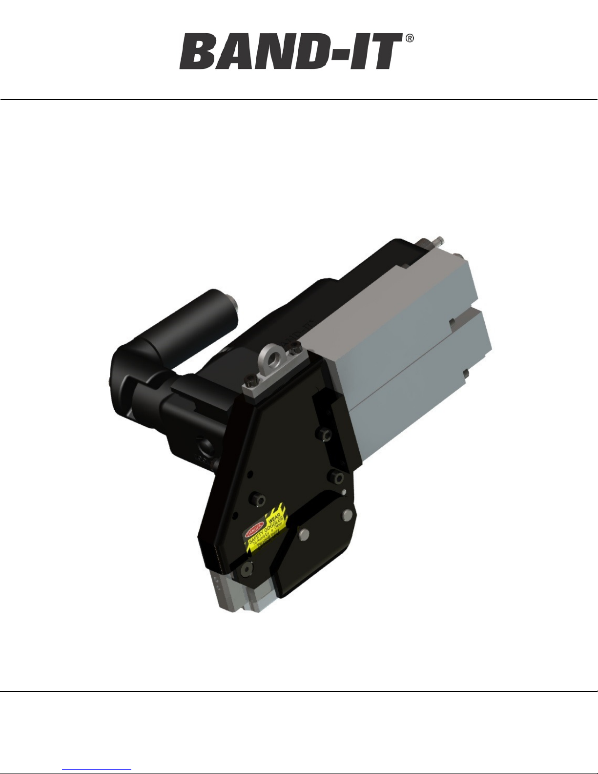
Operating
Manual
IT5000-C / IT6000-C
3/8” IT Tool
IT5000-C / IT6000-C
3/8” BAND-IT
®
Pneumatic IT Tools
Patent Pending
BAND-IT-IDEX, Inc.
A Unit of IDEX Corporation
4799 Dahlia Street
Denver, CO 80216-3070 USA
P: 1-800-525-0758
F: 1-800-624-3925
www.BAND-IT-IDEX.com
Page 1 of 36
Document # P48850 Rev. C
© Copyright
BAND-IT-IDEX, Inc. 2015
All rights reserved
Page 2
Operating
Manual
IT5000-C / IT6000-C
3/8” IT Tool
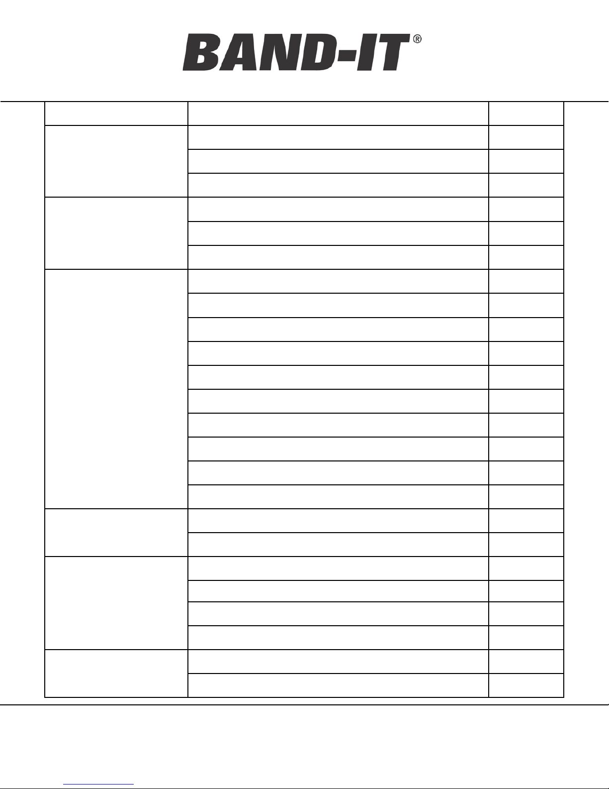
Topic Page Description Page #
Safety Safety Guidelines 3 - 5
Tool Overview 6
Introduction
Air System
Tool Operation
Model Identification & Options Review 6 - 7
Tool / Component Identification 8 - 9
Air System Requirements 10
Air Control Regulator 11-12
Air System Settings 13
Tie / Clamp Installation Procedure 14
IT Tool Orientation Requirements 15
Tie / Clamp Inspection 16
Clamp Placement 17
Dimple Clip 18
Adjustable Support Arm / Handle 19
Tool Clearance Requirements 20
Mounting & Fixturing 21-22
Remote Actuation Configuration 23
Cutoff Signal Option 24
Unable to Achieve Tension 25
Trouble Shooting
Tool Symptoms 26
Preventative Maintenance 27
Replacement Parts 28
Maintenance
Maintenance 29 – 34
Cutoff Timing Adjustment 35
Quality Assurance Test Equipment 36
Quality/Warranty
General Warranty Info 36
BAND-IT-IDEX, Inc.
A Unit of IDEX Corporation
4799 Dahlia Street
Denver, CO 80216-3070 USA
P: 1-800-525-0758
F: 1-800-624-3925
www.BAND-IT-IDEX.com
Page 2 of 36
Document # P48850 Rev. C
© Copyright
BAND-IT-IDEX, Inc. 2015
All rights reserved
Page 3
Operating
IT5000-C / IT6000-C
Manual
Safety Guidelines
This equipment has been tested by BAND-IT-IDEX and is safe to use providing that the
proper safety precautions are observed.
DANGER—Misuse of this equipment may result in serious injury to personnel.
• Only use the equipment for its intended purpose, as described in this manual
• Do not attempt to operate the equipment with covers removed
• Refer to the installation section before installing machine
• Do not operate machine with wet hands
Please read this entire manual before unpacking, setting up or operating this equipment.
Pay attention to all danger and caution statements. Failure to do so could result in serious
injury to the operator or other personnel, or damage to the equipment.
3/8” IT Tool
CAUTION—This equipment generates moderate levels of audible noise when in use.
• Ensure that it is installed in a location where operating noise will not cause disturbance.
Symbols:
Caution – Refer to accompanying documents
Caution – Risk of electric shock
It is the task of the employer to warn his or her staff of risks, to train them on prevention of
accidents, and to provide necessary safety equipment and devices for the operator’s safety.
Before starting to work with the machine, the operator should check the features of the
machine and learn all details of the machine’s operation. The machine should only be
operated by staff members who have read and understand the contents of this manual.
BAND-IT-IDEX, Inc.
A Unit of IDEX Corporation
4799 Dahlia Street
Denver, CO 80216-3070 USA
P: 1-800-525-0758
F: 1-800-624-3925
www.BAND-IT-IDEX.com
Page 3 of 36
Document # P48850 Rev. C
© Copyright
BAND-IT-IDEX, Inc. 2015
All rights reserved
Page 4
Operating
Manual
IT5000-C / IT6000-C
3/8” IT Tool
Directives de sécurité / Garantie
Cet équipement a été examiné par BAND-IT et est sûr pour employer fournir qu'on observe les
mesures de sécurité appropriées.
Danger-Abusez de cet équipement peut avoir comme conséquence des dommages sérieux au
personnel.
•
Utilisez seulement l'équipement pour son but prévu, comme décrit en ce manuel. N'essayez pas
d'actionner l'équipement des couvertures étant coupées
•
Reliez seulement à l'alimentation électrique correcte, comme indiqué de la plaque de contrôle
•
Référez-vous à la section d'installation avant d'installer la machine
•
N'actionnent pas la machine avec les mains humides
Veuillez lire ce manuel entier avant de déballer, installer ou actionner cet équipement. Prêtez l'attention
à tous les rapports de danger et d'attention. Le manque de faire ainsi a pu avoir comme conséquence
les dommages sérieux à l'opérateur, ou tout autre personnel, ou les dommages à l'équipement.
Attention-Cet équipement produit des niveaux modérés du bruit audible en service.
Assurez-vous qu'il est installé dans un endroit où le bruit de fonctionnement ne causera pas la
perturbation.
Symboles :
Attention - référez-vous aux documents d'accompagnement
Attention - risque de décharge électrique
C'est le charger de l'employeur pour avertir son personnel des risques d'accidents, pour les former sur
la prévention des accidents, et de fournir l'équipement et les dispositifs nécessaires de sûreté pour la
sûreté de l'opérateur.
Avant de commencer à travailler avec la machine, l'opérateur devrait vérifier les dispositifs de la
machine et apprendre tous les détails de l'opération de machine. La machine devrait seulement être
actionnée par les membres de personnel qui ont lu et comprendre le contenu de ce manuel.
BAND-IT-IDEX, Inc.
A Unit of IDEX Corporation
4799 Dahlia Street
Denver, CO 80216-3070 USA
P: 1-800-525-0758
F: 1-800-624-3925
www.BAND-IT-IDEX.com
Page 4 of 36
Document # P48850 Rev. C
© Copyright
BAND-IT-IDEX, Inc. 2015
All rights reserved
Page 5
Operating
IT5000-C / IT6000-C
Manual
Safety Guidelines
Environmental operating conditions are defined as:
• For Indoor Use ONLY
• Temperature range from 5°C to 40°C
• Max relative humidity 80% for temperatures up to 31°C. Allowable humidity then
decreases linearly to 50% at 40°C
• Conforms to Applicable Rated POLLUTION DEGREE 1
• Correct illumination for safety of operator (ISO 8995-89)
Additional Safety Guidelines:
• Read this manual and become familiar with the tool before installing any clamps.
3/8” IT Tool
• Protective eyewear should be worn when connecting and disconnecting the tool to
compressed air sources and during operation.
• Wear appropriate gloves for handling steel while operating this tool, applying steel
clamps and removing scrap clamp tail.
• Clamp tensioning can be immediately stopped by releasing the tool trigger. If a remote
trigger is used, the system must be connected to allow for immediate disabling of the tool.
• When applying clamps, care should be taken to insure fingers and loose clothing are not
in the way of the clamp being applied.
• Never attempt to clamp objects which have a potential to burst, shatter or otherwise
cause bodily harm.
• Disconnect air supply and electrical power prior to maintenance and disassembly of tool
components.
• Liquids or lubricants should never be put into the air lines.
BAND-IT-IDEX, Inc.
A Unit of IDEX Corporation
4799 Dahlia Street
Denver, CO 80216-3070 USA
P: 1-800-525-0758
F: 1-800-624-3925
www.BAND-IT-IDEX.com
Page 5 of 36
Document # P48850 Rev. C
© Copyright
BAND-IT-IDEX, Inc. 2015
All rights reserved
Page 6
Operating
Manual
IT5000-C / IT6000-C
3/8” IT Tool
Tool Overview
This machine is designed to automatically install clamps with repeatability and control.
• The tool consists of a tension system and a cutting system, both pneumatically controlled.
• The pneumatic system can be adjusted to provide appropriate clamp force for different
applications. As the tension pressure is increased, the output force of the tool increases.
• During the tension cycle, the tool continues to tension the band until the pre-set tension is
achieved. The tool stops tensioning when the pressure in the tension cylinder equals the inlet
tension pressure coming from the air controller module.
• After the tool has achieved the preset tension, a valve switches over to the cutoff cycle.
• The gripping system retains force on the clamp until after the knife is actuated, which forms a
locking feature and cuts the excess clamp tail.
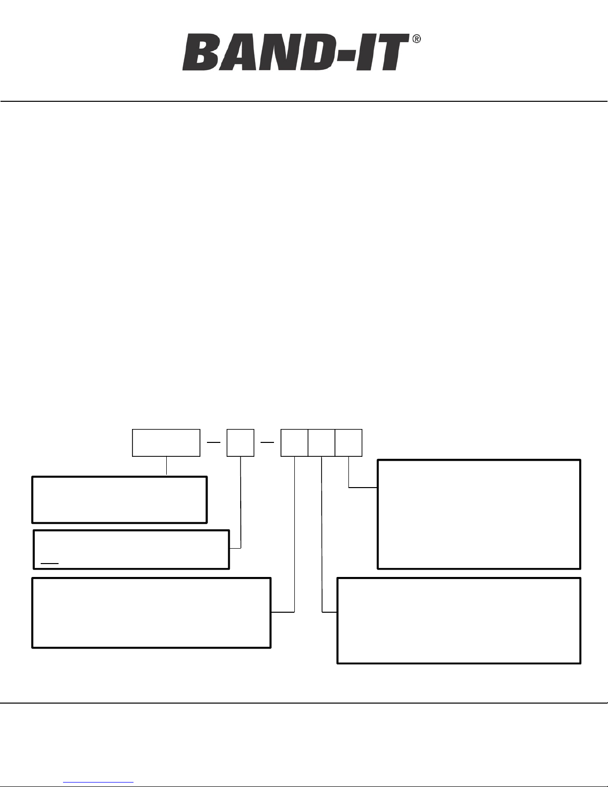
Model Identification
IT6000 C 0 0 0
Feedback options:
IT6000 – 3/8” Tie-Lok®Ties
IT5000 – 3/8” JR®Clamps
Product model: Revisions are
not compatible
Packaging options:
0 – Tool with standard accessories
1 – Tool only
Trigger options:
0 – Standard thumb trigger
1 – Connection for a remote trigger
0 – Standard Tool
1 – Data Feedback System
(obsolete)
2 – Cutoff Signal Sensor
(tool trigger disabled)
BAND-IT-IDEX, Inc.
A Unit of IDEX Corporation
4799 Dahlia Street
Denver, CO 80216-3070 USA
P: 1-800-525-0758
F: 1-800-624-3925
www.BAND-IT-IDEX.com
Page 6 of 36
Document # P48850 Rev. C
© Copyright
BAND-IT-IDEX, Inc. 2015
All rights reserved
Page 7

Operating
Manual
IT5000-C / IT6000-C
3/8” IT Tool
IT Tool Options
• Any IT tool can be ordered as a stand alone tool or with accessories. Accessories
packages all include a pneumatic air flow regulator. Additional accessories vary depending
on the tool options.
• The remote trigger option is a combination of a plumbing modification inside the tool, and a
sold separately foot pedal package. (see pg.19 for additional information)
• I17490 – Foot Pedal Control Kit, IT tools
• I17450 – Manual, Foot Pedal Kit
• The cutoff signal functions by a pneumatic switch set to trigger every cutoff cycle providing
an easy way to confirm and count clamps installed. The accessories option includes an 12ft
extension cord for connecting to the sensor.
• P48960 – Manual, Cutoff Signal
• The data system configuration is no longer available.
• P48950 – Manual, Data Feedback System
BAND-IT-IDEX, Inc.
A Unit of IDEX Corporation
4799 Dahlia Street
Denver, CO 80216-3070 USA
P: 1-800-525-0758
F: 1-800-624-3925
www.BAND-IT-IDEX.com
Page 7 of 36
Document # P48850 Rev. C
© Copyright
BAND-IT-IDEX, Inc. 2015
All rights reserved
Page 8
Operating
Manual
IT5000-C / IT6000-C
3/8” IT Tool
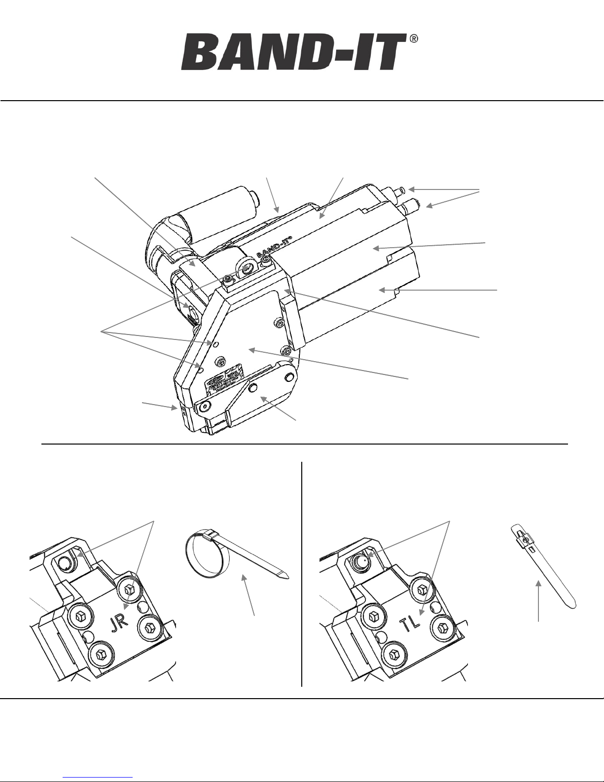
Tool / Component Identification
Operating Trigger
Tool
Reset
Tool
Mounting
Locations
Tool Head with
Knife and Cutter
Blade (see below)
Handle Cover
Handle
Quick Connect Air Couplings
(Do not add lubricants)
Tool Body
and Cover
Maintenance Cover w/
Tension Block Assembly
Tension
Cylinder
Cut-Off
Cylinder
Serial #
Location
IT5000-C / 3/8” JR®Clamps
“JR” on Cutter Blade
No Punch in Knife
3/8” JR Clamp 3/8” Tie-Lok Tie
BAND-IT-IDEX, Inc.
A Unit of IDEX Corporation
4799 Dahlia Street
Denver, CO 80216-3070 USA
P: 1-800-525-0758
F: 1-800-624-3925
IT6000-C / 3/8” Tie-Lok®Ties
www.BAND-IT-IDEX.com
Page 8 of 36
“TL” on Cutter Blade
Punch in Knife
Document # P48850 Rev. C
© Copyright
BAND-IT-IDEX, Inc. 2015
All rights reserved
Page 9
Operating
Manual
IT5000-C / IT6000-C
3/8” IT Tool
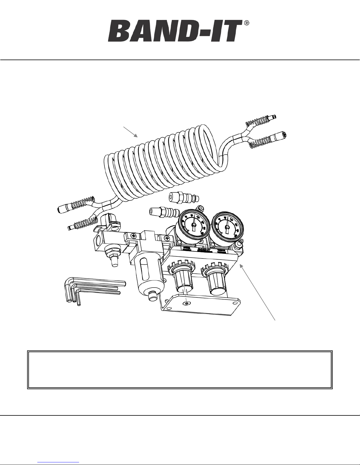
Identification of Standard Accessories
Coiled Air Lines
Packaging Option 0: Box includes IT tool, owners manual, air controller module,
coiled air line, hex keys and fittings
Packaging Option 1: Box includes the IT tool and manual only
BAND-IT-IDEX, Inc.
A Unit of IDEX Corporation
4799 Dahlia Street
Denver, CO 80216-3070 USA
P: 1-800-525-0758
F: 1-800-624-3925
www.BAND-IT-IDEX.com
Page 9 of 36
Air Regulator
Module
Document # P48850 Rev. C
© Copyright
BAND-IT-IDEX, Inc. 2015
All rights reserved
Page 10
Operating
Manual
IT5000-C / IT6000-C
3/8” IT Tool
Air System Requirements
For proper tool performance, the incoming compressed air requirements to the BAND-IT Air
Controller Module of the 3/8” BAND-IT Pneumatic IT Tool must be:
Item Min Max
Inlet Supply Pressure in PSI (kPa) 100 (690) 150 (1,034)
Inlet Supply Air Flow in SCFM (L/min) 1.5 (0.71)
Filtered air particle size (microns) (5)
Air Moisture Content 20% RH
Warning - Failure to follow the below specifications may cause significant damage to
internal tool components.
Although cylinders are permanently lubricated, premature wear can be caused by
contaminants in the air supply or the presence of water and oil. The tool’s internal
valves can also be affected by contaminants in the air lines causing a valve malfunction.
The BAND-IT Air Controller Module includes a filter to meet particle requirements.
BAND-IT recommends the use of an Air Booster System to address the potential problems
associated with low air supply, including:
•filters and dries the air supply
•assures pressure of 100 PSI (690 kPa)
Contact BAND-IT-IDEX Customer Service at 1-800-525-0758 or 303-320-4555 for more
information.
BAND-IT-IDEX, Inc.
A Unit of IDEX Corporation
4799 Dahlia Street
Denver, CO 80216-3070 USA
P: 1-800-525-0758
F: 1-800-624-3925
www.BAND-IT-IDEX.com
Page 10 of 36
Document # P48850 Rev. C
© Copyright
BAND-IT-IDEX, Inc. 2015
All rights reserved
Page 11
Operating
Manual
Air Supply
100-150 psi
IT5000-C / IT6000-C
3/8” IT Tool
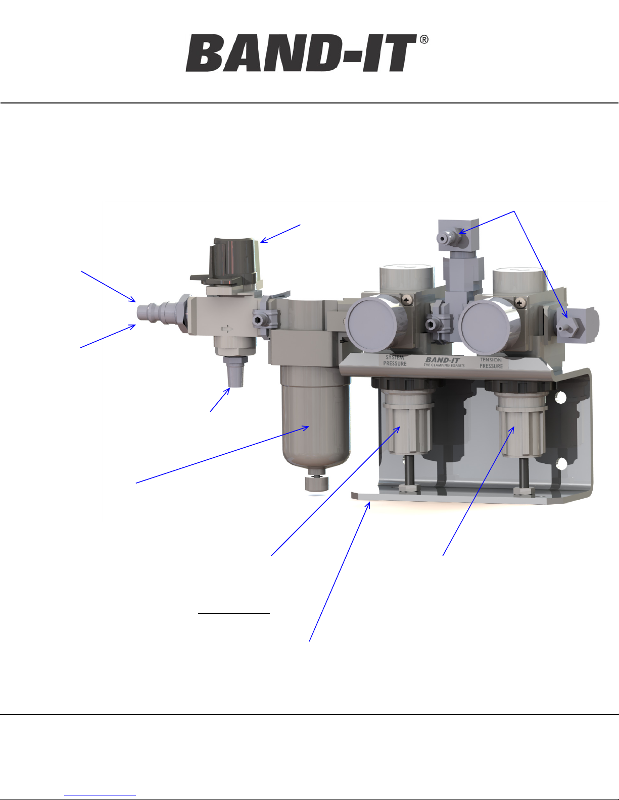
Air Control Regulator Assembly (I56090)
1/8” Quick Disconnects
Connect tool air hoses
Air Shut-Off
Valve
Quick Disconnect
Comes with “Industrial”
installed, also supplied with
Tru-Flate fitting.
Alternatively connect with
any ¼” npt fitting.
Muffler
Air Filter (5 micron)
Standard Filters/Regulators incorporate
polycarbonate bowls and/or observation
windows. Be sure any fluids used near
this assembly are compatible.
System Air Pressure
Regulator with Gauge
Factory set to 105 psi
Do not adjust
Mounting Bracket
Unit may be mounted
on wall or bench
Tension Pressure Regulator
with Gauge
Factory set to 70psi.
(suggested setting for IT6000)
Do not set higher than tool manual
listed maximum pressure. (pg.13)
To adjust, remove screw & nut pull
down on knob and twist. Push back
up and replace screw & nut to lock.
BAND-IT-IDEX, Inc.
A Unit of IDEX Corporation
4799 Dahlia Street
Denver, CO 80216-3070 USA
P: 1-800-525-0758
F: 1-800-624-3925
www.BAND-IT-IDEX.com
Page 11 of 36
Document # P48850 Rev. C
© Copyright
BAND-IT-IDEX, Inc. 2015
All rights reserved
Page 12

Operating
Manual
IT5000-C / IT6000-C
3/8” IT Tool
Regulator Mounting Holes
For proper performance the air control module must be mounted and operated in a horizontal
position as shown on the previous page. Below is the layout for the mounting hole locations
dimensioned in inches.
Hole layout for mounting to a wall
Hole layout for mounting to a bench
BAND-IT-IDEX, Inc.
A Unit of IDEX Corporation
4799 Dahlia Street
Denver, CO 80216-3070 USA
P: 1-800-525-0758
F: 1-800-624-3925
www.BAND-IT-IDEX.com
Page 12 of 36
Document # P48850 Rev. C
© Copyright
BAND-IT-IDEX, Inc. 2015
All rights reserved
Page 13

Operating
IT5000-C / IT6000-C
Manual
Air System Settings
Initial Setup – Pneumatic Settings
Connect the tool body to the Air Controller Module using the included Coiled Hose
Assembly. The hose assembly includes both a clear and black hose. Each hose end
includes a female and male fitting, arranged to prevent reversing of connections.
Connect Air Controller Module to air source (assure air supply meets requirements on “Air
System Requirements” page) and turn RED Shut-off Valve to pressurize tool (supply
position).
IT5000-C / 3/8” JR®Clamps IT6000-C / 3/8” Tie-Lok® Ties
3/8” IT Tool
Minimum
Recommended
Maximum
Cut-Off
Pressure
100 PSI
(690 kPa)
105 PSI
(725 kPa)
110 PSI
(760 kPa)
Tension
Pressure
60 PSI
(410 kPa)
85 PSI
(585 kPa)
90 PSI
(620 kPa)
Cut-Off
Pressure
100 PSI
(690 kPa)
105 PSI
(725 kPa)
110 PSI
(760 kPa)
Tension
Pressure
50 PSI
(345 kPa)
70 PSI
(480 kPa)
75 PSI
(520kPa)
Caution: Tension pressures above the specified settings may cause premature
clamp failure and/or tool wear. Refer to the “Tool / Component Identification” page
to verify the tool model.
Setting the Tool Air Pressure
The tension pressure directly affects the force applied to the clamp.
To correctly set the air pressure from the air controller module going to the tool, connect the
air supply to the tool. Activate the tool by depressing the trigger for a few seconds. Re-read
the pressure when the tool is at rest and adjust again if necessary. Repeat until the desired
pressure is shown on the tension pressure gage.
Tension pressure may need to be adjusted to provide adequate tension for the specific
application.
BAND-IT-IDEX, Inc.
A Unit of IDEX Corporation
4799 Dahlia Street
Denver, CO 80216-3070 USA
P: 1-800-525-0758
F: 1-800-624-3925
www.BAND-IT-IDEX.com
Page 13 of 36
Document # P48850 Rev. C
© Copyright
BAND-IT-IDEX, Inc. 2015
All rights reserved
Page 14

Operating
Manual
Tie-Lok® Tie / Jr®Clamp Installation Procedure
1. (Tie-Lok Tie only) Lace the tie snug around
the assembly and locate the buckle in the
target location.
2. Band should be applied to a uniform solid
surface allowing the buckle adequate support
during the clamp locking and clamp tail cut-off
operation. (pg. 17)
3. Insert the tail of the clamp all the way through
the tool bringing the tool head as close to the
buckle as possible. The tail length extending
into tool must be at least 2.5” (6.4 cm) long.
IT5000-C / IT6000-C
3/8” IT Tool
4. Do not activate tool while inserting clamp tail
because this can cause tie tail to jam in the
Tension Block Assembly.
5. Ensure proper tool orientation. (pg. 15)
6. Begin tensioning by pushing and holding down
operating trigger or by using the remote
trigger system. If the trigger is released, the
tool will cease operation if the desired tension
has not been achieved.
7. While tensioning clamp, allow the tool to move
freely.(pg.15) Continue to hold down operating
trigger until tool completely tensions and cuts
off clamp. Release trigger after cut off.
8. After clamp is completed, clamp tail scrap
must be removed from tool. Clamp tail scrap
is not ejected automatically. Tool is now ready
for next tie/clamp.
Note: Trigger activation requires approximately 3 lbs.f
BAND-IT-IDEX, Inc.
A Unit of IDEX Corporation
4799 Dahlia Street
Denver, CO 80216-3070 USA
P: 1-800-525-0758
F: 1-800-624-3925
www.BAND-IT-IDEX.com
Page 14 of 36
Document # P48850 Rev. C
© Copyright
BAND-IT-IDEX, Inc. 2015
All rights reserved
Page 15

Operating
Manual
IT5000-C / IT6000-C
3/8” IT Tool
IT Tool Orientation Requirements
The BAND-IT Pneumatic IT Tool must be used correctly in order to reliably install a clamp.
Part of ensuring that the tool is producing a strong lock is making sure that it approaches the
application correctly and the fixture configuration allows repeatability of application.
• The tool should approach the assembly in the same orientation that it will finish a clamp
installation. Typically around 20°relative to the surface of the work piece.
• The tool head should come close to the buckle and work piece after inserting the clamp
tail.
• Tie-Lok Ties, have the dimple clip start to engage the buckle.
• JR clamps, stage the tool slightly above the clamp.
• The buckle should be located in the final target area on the assembly.
• Once the tool begins tensioning, allow the band to pull the tool down to the surface.
• As the band is tensioning, the tool may rotate clockwise above the buckle as in direction 1
(Green Arrow).
• During cut-off, the tool must be allowed to rotate counter-clockwise up to 35 degrees in
direction 2 (Blue Arrow).
Typically
20°- 25 °
BAND-IT-IDEX, Inc.
A Unit of IDEX Corporation
4799 Dahlia Street
Denver, CO 80216-3070 USA
P: 1-800-525-0758
F: 1-800-624-3925
1
2
www.BAND-IT-IDEX.com
Page 15 of 36
Document # P48850 Rev. C
© Copyright
BAND-IT-IDEX, Inc. 2015
All rights reserved
Page 16

Operating
Manual
Tie / Clamp Inspection
The IT6000-C forms a locking dimple into
the Tie-Lok tie with the punch and cuts the
remaining tail. When installing a Tie-Lok tie,
a visual check is recommended to verify the
presence of a locking dimple after the tie
has been applied.
Locking Dimple
IT5000-C / IT6000-C
3/8” IT Tool
The IT5000-C forms a locking lip on the
preformed JR clamp and cuts the remaining
tail. When installing a JR clamp, a visual
check is recommended to verify the
presence of the locking lip after the clamp
has been applied.
Locking Lip
By controlling and monitoring the items that are needed to form a good lock, an operator
can help ensure that the clamp will be applied correctly without having to inspect every
assembly. The key issues are:
• Adequate air pressure and volume (Pg.10)
• Appropriately setting the tension and cutoff air pressure for the application (Pg.13)
• Angle of approach (Pg.15)
• Operator Handling Ergonomics (Pg.19)
• Mounting the tool on a weight balancer or custom fixture (Pg.21)
• Following the recommended Preventative Maintenance schedule (Pg.25)
BAND-IT-IDEX, Inc.
A Unit of IDEX Corporation
4799 Dahlia Street
Denver, CO 80216-3070 USA
P: 1-800-525-0758
F: 1-800-624-3925
www.BAND-IT-IDEX.com
Page 16 of 36
Document # P48850 Rev. C
© Copyright
BAND-IT-IDEX, Inc. 2015
All rights reserved
Page 17

Operating
Manual
IT5000-C / IT6000-C
3/8” IT Tool
Clamp Placement
Buckle location is critical to clamp performance. Use the following guidelines as a reference.
• Band target area must be wider that the band and tool head with some additional
clearance for variation side to side.
• Do not install clamps at an angle
• Buckle locations cannot be over air gaps
• Avoid installing buckles on flat surfaces when possible
• On large oval shapes locate buckle on smaller
radius.
• Do not install clamps around square corners
• Do not install clamps on tapered surfaces or on tube bends
• Tie-Lok & JR Clamp advised min installed diameter is 1”
For specific questions contact BAND-IT-IDEX Customer Service at 1-800-525-0758 or
303-320-4555 for more information.
BAND-IT-IDEX, Inc.
A Unit of IDEX Corporation
4799 Dahlia Street
Denver, CO 80216-3070 USA
P: 1-800-525-0758
F: 1-800-624-3925
www.BAND-IT-IDEX.com
Page 17 of 36
Document # P48850 Rev. C
© Copyright
BAND-IT-IDEX, Inc. 2015
All rights reserved
Page 18

Operating
Manual
IT5000-C / IT6000-C
3/8” IT Tool
Dimple Clip Guide (IT6000 only)
• The dimple clip is designed to eliminate the occurrence of undetectable loose ties.
This provides a positive visual indicator to identify good vs. bad tie installation.
• Installing the clip
– Step 1: Locate clip on front of tool head
– Step 2: Install M4x5 screw to hold clip in place. Do not exceed 6 newton meters
(N-m) torque. [ 53 inch pounds (in-lb) ] Over tightening will cause the screw thread
to strip.
• Tool orientation is critical to proper function. The tool must be aligned so the clip is
contacting the work piece while the clamp is being tensioned in order to make sure
the buckle locates inside clip during assembly.
• If the blade is not contacting the work piece during clamp tensioning, the clip will
overshoot the buckle. When the buckle slides under the clip, the dimple lock
cannot form and the tie will be loose. There will also be a sharp edge after cutoff.
CORRECTINCORRECT
BAND-IT-IDEX, Inc.
A Unit of IDEX Corporation
4799 Dahlia Street
Denver, CO 80216-3070 USA
P: 1-800-525-0758
F: 1-800-624-3925
www.BAND-IT-IDEX.com
Page 18 of 36
Document # P48850 Rev. C
© Copyright
BAND-IT-IDEX, Inc. 2015
All rights reserved
Page 19

Operating
IT5000-C / IT6000-C
Manual
Adjustable Support Arm / Handle for Hand Use
• Using a hex key (supplied), adjust the Support Arm/Handle to ergonomically match
the operators hand.
• Be sure not to adjust the Handle too far
outward (beyond interlocking legs) or the
handle will not function properly or
provide support to the operator.
3/8” IT Tool
Hex Key
Tool Ergonomics
• Tool weight – 7 Pounds (3.2 Kg)
• A Neutral wrist position is recommended
• A bent wrist can cause operator fatigue, and tool misuse
• Any fixture design should attempt to replicate the natural
human wrist / elbow / shoulder motions that would occur
when operating the tool in the hand-held configuration,
allowing the tool to float along a plane through the entire
Tension (pull-up) and Cut-Off (lock) process.
BAND-IT-IDEX, Inc.
A Unit of IDEX Corporation
4799 Dahlia Street
Denver, CO 80216-3070 USA
P: 1-800-525-0758
F: 1-800-624-3925
www.BAND-IT-IDEX.com
Page 19 of 36
Document # P48850 Rev. C
© Copyright
BAND-IT-IDEX, Inc. 2015
All rights reserved
Page 20

Operating
Manual
IT Tool Clearance Requirements
There are three common considerations for tool clearance
1. Channel Flat width (D)
• Must be wider than the blade (A) 0.96” [24.4mm]
2. Raised width (E)
• Must be wider than flip cover (B) 1.38” [35.1mm]
when between 0.23” - 1.5” [5.8 - 38.1mm] tall
• Must be wider than the pins (C) when taller than
1.5” [38.1mm]
3. Shoulder height (F) depends on tool orientation
• When under the handle, must be less than 2”
• When away from handle, width must increase to
give clearance to air cylinders, but no height
limitation.
IT5000-C / IT6000-C
3/8” IT Tool
Front
View
A. Blade width
• 0.96” [24.4mm]
B. Flip cover width
• 1.38” [35.1mm]
C. Pin
D. Flat width
• > 0.96” [24.4mm]
E. Channel width
• > 1.38” [35.1mm]
F. Shoulder height
• < 2” [50.8mm]
C
B
D
A
F
E
BAND-IT-IDEX, Inc.
A Unit of IDEX Corporation
4799 Dahlia Street
Denver, CO 80216-3070 USA
P: 1-800-525-0758
F: 1-800-624-3925
www.BAND-IT-IDEX.com
Page 20 of 36
Document # P48850 Rev. C
© Copyright
BAND-IT-IDEX, Inc. 2015
All rights reserved
Page 21

Operating
Manual
IT5000-C / IT6000-C
3/8” IT Tool
Fixture Hanger
At a minimum BAND-IT recommends that the tool be connected to a weight balancer
or be mounted in a fixture that will provide adequate rotation during operation.
• Support boom & Balancer
• 4 axis of movement
to locate tool directly
over target clamp
location.
• The balancer must
support a tool weight
of approximately 7 lb.
Swing Arm
Weight
Balancer
IT Tool
The tool comes with a hanger loop installed on the top face to mount to a weight balancer.
When removed, there are four M5 threads that can be used to secure the tool to a fixture. The
included tool hanger may be attached to any of the mounting holes as shown below.
Caution: do not allow screws to extend deeper than 7/16” (0.438”) into the tool
body. Longer screws will interfere with the internal components of the tool and
cause tool to jam.
BAND-IT-IDEX, Inc.
A Unit of IDEX Corporation
4799 Dahlia Street
Denver, CO 80216-3070 USA
P: 1-800-525-0758
F: 1-800-624-3925
www.BAND-IT-IDEX.com
Page 21 of 36
Document # P48850 Rev. C
© Copyright
BAND-IT-IDEX, Inc. 2015
All rights reserved
Page 22

Operating
Manual
Three additional fixture
mounting holes are available
to assist with mounting the
tool. Thread size is M5 for all
holes.
One hole is utilized to attach
and lock the tool body cover
to the tool body. This hole
may also be used for a fixture,
provided the M5 cap screw is
replaced with a similar screw
with appropriate thread
length.
IT5000-C / IT6000-C
3/8” IT Tool
Fixture Mounting Holes
Fixture guide for Tie-Lok®Ties
The center block should allow for the buckle to pass around the work piece
This will allow the tie to be threaded from either end
Clamp guild material should be
heat treated tool steel
BAND-IT-IDEX, Inc.
A Unit of IDEX Corporation
4799 Dahlia Street
Denver, CO 80216-3070 USA
P: 1-800-525-0758
F: 1-800-624-3925
www.BAND-IT-IDEX.com
Page 22 of 36
Document # P48850 Rev. C
© Copyright
BAND-IT-IDEX, Inc. 2015
All rights reserved
Page 23

Operating
Manual
IT5000-C / IT6000-C
3/8” IT Tool
Remote Actuation Configuration
• A tool with trigger option 0 is manually operated via the thumb button. A tool with trigger
option 1 is configured to allow remote operation via palm button or other device permitting
the tool to be incorporated into the customer’s fixture or assembly process.
• The modification consists of deactivating the thumb lever actuation switch and installing two
6-ft X 1/8” O.D. hoses with quick disconnects. These lines can be connected to any valve
used as a remote actuation device. Examples include palm buttons, foot control pedals,
and others.
• Various actuation devices can be incorporated based upon end user requirements. Basic
schematic for 2-way & 3-way valves included below. The valve should be set up in the
normally closed mode and upon opening the circuit a supply of air is provided.
• The customer is responsible for incorporating this tool into their process. BAND-IT-IDEX is
available to provide advice and recommendations.
Remote trigger: 2-way valve
Hose from tool
(male quick disconnect)
Actuate to
stop tool
Supply Hose from
tool (female quick disconnect)
Remote trigger: 3-way valve
Hose from
tool (male)
Actuate to
stop tool
Actuate to
start tool
Actuate to
start tool
Multiple Triggers
Hose from tool
(male)
If more than one trigger is used,
connect in series. All need to be
actuated to run the tool.
Supply Hose from
tool (female)
Supply Hose from
tool (female)
BAND-IT-IDEX, Inc.
A Unit of IDEX Corporation
4799 Dahlia Street
Denver, CO 80216-3070 USA
P: 1-800-525-0758
F: 1-800-624-3925
www.BAND-IT-IDEX.com
Page 23 of 36
Document # P48850 Rev. C
© Copyright
BAND-IT-IDEX, Inc. 2015
All rights reserved
Page 24

Operating
Manual
IT5000-C / IT6000-C
3/8” IT Tool
Cutoff Signal Option
The cut-off signal option provides a signal from the tool that indicates the completion of a
clamp installation. Pressurization of the cut-off cylinder activates a pressure switch when
the tool switches from the tension cycle to the cut-off cycle. The pressure switch is
“normally open” and closes to complete a circuit when cut-off cylinder pressure exceeds
45±15 psi during cutoff cycle. The signal can be transmitted to a data collection device,
such as a PLC, via the 12-foot extension cable and used as a counter to track the number
of clamps applied by the tool. The switch has a maximum voltage rating of 42V.
The -002 and -012 configurations are tool
systems that also come with a 12-foot
extension cable (I60387), female receptacle
(I60487) and electric panel lock nut (I61187)
for mounting to a PLC or other control box. The
polarity of the 2 wire leads from the receptacle
is not critical.
An IT Tool with configurations -102 and -112
contain the pressure switch and 2 pole Micro
AC series male receptacle.
Mounting Hole:
½”-14 NPT
Or
.85” diameter clearance hole for ½”-14 lock nut
Contact BAND-IT IDEX Customer Service at 1-800-525-0758 or 303-320-4555 for
any questions not addressed above.
BAND-IT-IDEX, Inc.
A Unit of IDEX Corporation
4799 Dahlia Street
Denver, CO 80216-3070 USA
P: 1-800-525-0758
F: 1-800-624-3925
www.BAND-IT-IDEX.com
Page 24 of 36
Document # P48850 Rev. C
© Copyright
BAND-IT-IDEX, Inc. 2015
All rights reserved
Page 25

Operating
IT5000-C / IT6000-C
Manual
Trouble Shooting Guide: Unable to Achieve Tension
If the tool fails to fully tension the clamp:
Failure to fully tension the clamp can be caused by a variety of factors. The two
most common factors are incorrect tension pressure and problems with the grippers.
• Check tension pressure setting on Tension Pressure Gauge of Air Controller Module.
Adjust pressure per the settings found in the “Air System Settings” page.
• Evaluate the clamp tail dimple pattern. If elongated dimples are present, the problem
may be with the Tension Block or Front Gripper.
Front Gripper Tension Block
3/8” IT Tool
Normal clamp tail dimple
pattern.
Clamp tail dimple pattern
indicates a problem
• If a problem is indicated, follow the instructions in the “Maintenance” section to remove
and inspect the tension block assembly and the front gripper.
• Examine the Tension Block and Tension Gripper for damage or wear.
• Examine the Front Gripper area for foreign debris and/ or buildup of metal shavings.
• Ensure that the four cutter blade screws are tightened.
• If excessive damage or wear is determined, replace the worn parts.
A worn out tension block:
Edge is no longer sharp, or is chipped
BAND-IT-IDEX, Inc.
A Unit of IDEX Corporation
4799 Dahlia Street
Denver, CO 80216-3070 USA
P: 1-800-525-0758
F: 1-800-624-3925
A worn out tension gripper:
Ridges are worn off in some sections
www.BAND-IT-IDEX.com
Page 25 of 36
Document # P48850 Rev. C
© Copyright
BAND-IT-IDEX, Inc. 2015
All rights reserved
Page 26

Operating
Manual
Symptom Items to check Suggested fix
IT5000-C / IT6000-C
3/8” IT Tool
Trouble Shooting Guide: Tool Symptoms
Difficulty inserting
clamp tail into tool
Tool does not cycle
when the trigger is
pressed
Tool tightens clamp,
but cutoff does not
activate
Tool attempts to cutoff
and lock the clamp
before it is tight
Is there a clamp tail already in
Remove previous clamp tail
the tool?
Do the gages on the control
module show pressure?
Do the gages on the control
module show pressure?
Check incoming supply pressure.
Turn the air regulator valve ON.
Check incoming supply pressure.
Turn the air regulator valve ON.
Check for pinched air lines under
the handle cover.
After the tool stalls, does
nothing further happen? (no
Check for pinched air lines.
Check cutoff timing.
sound of the cylinder moving)
Does the cylinder sound as
though it moves, but the knife
does not extend?
Remove the side body and verify all
links are present and connected.
Verify there is a knife installed.
Is the cutoff timing too short? Adjust cutoff timing.
Is the tool struggling to pull up
the clamp?
Increase tension pressure.
Lubricate the tool.
Tool fails to cut or
lock clamp.
Check tension and cutoff
pressures
(Press reset button to
release tool from
clamp if stalled)
Check knife and blade for
excessive wear or chips on
the cutting edges.
Contact BAND-IT-IDEX Customer Service at 1-800-525-0758 or 303-320-4555 for
repair on any issues not addressed above.
BAND-IT-IDEX, Inc.
A Unit of IDEX Corporation
4799 Dahlia Street
Denver, CO 80216-3070 USA
P: 1-800-525-0758
F: 1-800-624-3925
Adjust pressure regulators if not set
at specification. Verify that the hose
from the tension regulator enters the
bottom port of the tool.
Replace as necessary.
www.BAND-IT-IDEX.com
Page 26 of 36
Document # P48850 Rev. C
© Copyright
BAND-IT-IDEX, Inc. 2015
All rights reserved
Page 27

Operating
Manual
IT5000-C / IT6000-C
3/8” IT Tool
Preventative Maintenance
The tool has components that must be checked and/or replaced on a regular schedule. If
tools are experiencing difficulties during function or there are audible air leaks coming from
inside the handle, the tool should be returned to BAND-IT for service. Pneumatic components
must be serviced by BAND-IT in order to assure proper tool performance after a repair.
Clamps
Installed
Maintenance
Item
Maintenance
Action
Maintenance Cover (pg. 27) Clean & Re-Lubricate
Tension Block and Gripper (pg. 28) Inspect, Clean, Re-Lubricate
Every 25,000
Front Gripper (pg. 29) Clean & Re-Lubricate
Cutter Blade & Blade Screws (pg. 29)
Inspect & Replace if necessary
Tool Cavity, Tool Head, Linkages (pg. 30) Clean & Re-Lubricate
Every 50,000
Knife and Dimple Punch (pg. 31) Inspect & Replace if necessary
Every 100,000
Head Pin and Front Cutoff Lever Inspect & Replace if necessary
Some applications and environments may require maintenance intervals to be adjusted.
Consult BAND-IT-IDEX for more information.
For best performance and to extend tool life:
• Follow preventative maintenance and parts replacement instructions at appropriate service
intervals.
• Do not remove factory applied lubrication from inside tool unless performing a thorough
maintenance procedure and then replacing with fresh lubricant immediately.
• Do not use degreaser in the tool body.
• Do not spray any lubricant or cleaner into the Quick Connect Air Couplings.
• Use nominal recommended tension setting (see “Air System Settings” page). Tension
pressures above the specified settings may cause premature clamp failure and/or tool wear.
• For maintenance beyond what is described in this manual, consult BAND-IT-IDEX Customer
Service at 1-800-525-0758 or 303-320-4555 .
BAND-IT-IDEX, Inc.
A Unit of IDEX Corporation
4799 Dahlia Street
Denver, CO 80216-3070 USA
P: 1-800-525-0758
F: 1-800-624-3925
www.BAND-IT-IDEX.com
Page 27 of 36
Document # P48850 Rev. C
BAND-IT-IDEX, Inc. 2015
All rights reserved
© Copyright
Page 28

Operating
Manual
IT5000-C / IT6000-C
3/8” IT Tool
Maintenance: Replacement Parts
Production tools will experience wear of specific parts. High cycle tools may experience a
component failure that is not considered a wear part. Preventative maintenance, including
regular cleaning and lubrication will reduce the replacement frequency of these parts. Threaded
fasteners may be replaced by off the shelf parts, but they must be an identical replacement or
tool function may be affected.
Part # Description
I51065
I51066
I51069
I51067
I51004
I51057
I40087
I51064
M24187
I14387
Maintenance Cover Assembly: includes assembled maintenance cover,
two clevis pins, two retaining rings (pg. 27)
Tension Block Assembly: includes tension block, tension gripper,
tension pin, and 2 springs (pg. 28)
IT6000-C Cutter Blade with four screws (pg. 29)
IT6000-C Knife Assembly Kit: includes assembled knife, dimple punch,
and spring pin (pg. 31)
IT5000-C Knife (pg. 31)
IT5000-C Cutter Blade (pg. 29)
Hanger bracket; for attaching tool balancer (seen on pg. 7)
Front gripper ball (pg.29)
Front cutoff lever (pg.31, step 5, attached to knife)
Head pin (pg.31, pin retaining M24187 to head)
Socket head cap screws M5 x 10mm; for balancer bracket & cover plate
Lubricant, Chevron Rykotac Grease EP (or equivalent)
Several fasteners require Loctite, Blue - Medium strength.
Please have both the tool model and serial numbers available when calling the factory for
service or assistance. Contact BAND-IT-IDEX Customer Service at 1-800-525-0758 or
303-320-4555 for more information. Part numbers are subject to change.
BAND-IT-IDEX, Inc.
A Unit of IDEX Corporation
4799 Dahlia Street
Denver, CO 80216-3070 USA
P: 1-800-525-0758
F: 1-800-624-3925
www.BAND-IT-IDEX.com
Page 28 of 36
Document # P48850 Rev. C
© Copyright
BAND-IT-IDEX, Inc. 2015
All rights reserved
Page 29

Operating
Manual
Maintenance: Maintenance Cover
Important: Before disassembling tool, be sure to shut-off air supply on the
Control Module.
Note: This tool uses metric fasteners.
1) Remove the two e-style
retaining rings and two clevis
pins. Remove the
maintenance cover.
2) Remove the tension block
assembly by lifting it out of
tension arm slot. Tension block
may come out with
maintenance cover.
IT5000-C / IT6000-C
3/8” IT Tool
3) Fully clean and lubricate inside
of maintenance cover as
shown.
Lightly lubricate all
points indicated
with red arrows.
Maintenance Cover
***Continued on next page***
Tension
Block
Assembly
BAND-IT-IDEX, Inc.
A Unit of IDEX Corporation
4799 Dahlia Street
Denver, CO 80216-3070 USA
P: 1-800-525-0758
F: 1-800-624-3925
www.BAND-IT-IDEX.com
Page 29 of 36
Document # P48850 Rev. C
© Copyright
BAND-IT-IDEX, Inc. 2015
All rights reserved
Page 30

Operating
Manual
IT5000-C / IT6000-C
3/8” IT Tool
Maintenance: Tension Block Inspection & Replacement
Disassembly & Inspection:
1) Remove the two Compression Springs.
2) Remove Tension Gripper and Tension Block pin from the Tension Block.
3) Tension Gripper — Look for worn spots or other damage.
4) Tension Block — Look for damaged edge on insert or other damage. See the “Trouble
Shooting Guide: Unable to Achieve Tension” page 24 for details.
Reassembly:
1) Thoroughly clean out any accumulated debris from inside the Tension Block
2) Lubricate the surfaces shown with red arrows
3) Install the Tension Gripper and Tension Block Pin in the Tension Block.
4) Reinstall the Compression Springs
Tension Gripper
Clean out any
accumulated debris
from the slot in the
Tension Block
Compression SpringsTension Block
Tension Block Pin
Lightly lubricate all outside surfaces
of tension block and surfaces
indicated with red arrows.
Insert
Note: Ensure no lubrication is present in
the center of Tension Gripper (indicated
by the circled area)
BAND-IT-IDEX, Inc.
A Unit of IDEX Corporation
4799 Dahlia Street
Denver, CO 80216-3070 USA
P: 1-800-525-0758
F: 1-800-624-3925
www.BAND-IT-IDEX.com
Page 30 of 36
Document # P48850 Rev. C
© Copyright
BAND-IT-IDEX, Inc. 2015
All rights reserved
Page 31

Operating
Manual
Maintenance: Cutter Blade Inspection & Replacement
Removal & Installation:
1) Remove the four M4 screws with a 3mm hex
key. This can occur with the tool fully
assembled.
2) Pull the cutter blade off of the two alignment pins
in the tool head.
3) Inspect cutter blade for chips and excessive
wear on cutting edge. Replace if blade is
causing unacceptable clamp cut-off. Clean any
shavings or debris that have built up on cutter
blade.
IT5000-C / IT6000-C
3/8” IT Tool
Cutter Blade
4) Remove all accumulated shavings and debris
from inside the front gripper where the ball
bearing is inserted. The part can be pulled back
and out of the tool head slot.
5) Lubricate ball bearing after cleaning.
6) To re-install cutter blade, use alignment pins and
install the four M4 screws with blue Loctite.
Ball
Bearing
Front Gripper
BAND-IT-IDEX, Inc.
A Unit of IDEX Corporation
4799 Dahlia Street
Denver, CO 80216-3070 USA
P: 1-800-525-0758
F: 1-800-624-3925
www.BAND-IT-IDEX.com
Page 31 of 36
Document # P48850 Rev. C
© Copyright
BAND-IT-IDEX, Inc. 2015
All rights reserved
Page 32

Operating
Manual
IT5000-C / IT6000-C
3/8” IT Tool
Maintenance: Tool Body and Linkages
1) Remove the three cap screws (4mm hex) and the one flat head screw (3mm hex) as
shown.
2) Remove the side cover after screws are removed. The side cover is a close fit and may
require a screwdriver to pry off near the tension arm.
3) Examine the mechanical linkages for over-all condition such as dirt, metal filings, liquid
contamination and lubrication.
Pry Here
BAND-IT-IDEX, Inc.
A Unit of IDEX Corporation
4799 Dahlia Street
Denver, CO 80216-3070 USA
P: 1-800-525-0758
F: 1-800-624-3925
www.BAND-IT-IDEX.com
Page 32 of 36
Document # P48850 Rev. C
© Copyright
BAND-IT-IDEX, Inc. 2015
All rights reserved
Page 33

Operating
Manual
IT5000-C / IT6000-C
3/8” IT Tool
Maintenance: Knife Inspection & Replacement
1) Remove the one cutoff link and two pins shown
2) Remove the tool head by removing one flat head screw (3mm hex) on opposite side
3) Remove tool head assembly by sliding it along keyway in tool body
4) Lift cutter arm and knife assembly out of tool head
5) Push the pin out of knife assembly to remove the cutter arm
6) Inspect cutting edge for chips and excessive wear. Make sure knife is well lubricated.
7) For IT6000-C only: the Dimple Pin height should be 0.120” minimum. Inspect dimple pin
for excessive wear.
Note: Be careful not to let ball bearing fall out of gripper guide. Further cleaning of the gripper
guide and ball bearing can occur here if necessary.
Step 1
Step 4
Lightly lubricate all
sides of cutting knife.
Step 5
Front
Cutoff
Lever
Cutting Edge
Step 3
BAND-IT-IDEX, Inc.
A Unit of IDEX Corporation
4799 Dahlia Street
Denver, CO 80216-3070 USA
P: 1-800-525-0758
F: 1-800-624-3925
Head Pin
Dimple Pin Height
0.120” Minimum
www.BAND-IT-IDEX.com
Page 33 of 36
Document # P48850 Rev. C
© Copyright
BAND-IT-IDEX, Inc. 2015
All rights reserved
Page 34

Operating
Manual
IT5000-C / IT6000-C
3/8” IT Tool
Maintenance: Lubrication
Important: Before disassembling tool, be sure to shut-off air supply on the
Control Module.
Note: This tool uses metric fasteners.
The recommended lubricant is Chevron Rykotac Grease EP.
1) Lubricate tool cavity as shown with red arrows below. Also, lubricate the inside surfaces of
the maintenance cover (shown below).
2) BAND-IT recommends lubrication every 25,000 clamps. Dirty environments may require
more frequent intervals.
3) Inspect all mechanical linkages for lubrication and proper placement. Refit cover.
4) Secure the tool side cover by inserting and tightening the screws to 20-30 in-lbs removed
on the previous page’s steps. Apply medium strength blue Loctite to the 3 cap screws and
high strength red Loctite to the one flat head screw.
Tool Cavity
Lightly lubricate all points
indicated with red arrows.
BAND-IT-IDEX, Inc.
A Unit of IDEX Corporation
4799 Dahlia Street
Denver, CO 80216-3070 USA
P: 1-800-525-0758
F: 1-800-624-3925
www.BAND-IT-IDEX.com
Page 34 of 36
Document # P48850 Rev. C
© Copyright
BAND-IT-IDEX, Inc. 2015
All rights reserved
Page 35

Operating
Manual
IT5000-C / IT6000-C
3/8” IT Tool
Maintenance: Cutoff Timing Adjustment
1) Remove the two cap screws in the Handle Cover with a 4mm hex key. Remove cover and
lay aside during their removal.
2) The valve used to adjust timing is highlighted in the picture below.
3) To adjust: Loosen jam nut, and turn adjustment screw clockwise to increase the cutoff delay
and counter-clockwise to decrease the cutoff delay. Once the delay is set, tighten the jam
nut against the adjustment screw.
4) To test and verify proper adjustment: Connect the tool to the Air Control Module, then turn
supply valve on. Gently kink the coiled air supply tube connected to the bottom Quick
Connect Air Coupling, then activate the Tool Trigger. This action causes the tool to cut off,
allowing the timing to be reviewed. Adjusting the Timing Screw in by ½ turn will slow the
tool’s cut-off action. Adjusting the Timing Screw out by a half turn increases the speed of
the cut-off activation. Repeat this entire step until timing is set at a 0.5 – 1.0 second delay.
Caution: Setting timing to less than 0.5s may result in loose clamps.
Cutoff Timing
Valve
Notes:
-Cut-off timing set too short will not allow the clamp to achieve the desired tension before
switching to the cut-off function causing a loose clamp. Clamping on softer objects requires
a longer timing.
-Cut-off timing set too long may slow production and cause operator to twist the tool during
application. This may damage tool and/or clamp.
BAND-IT-IDEX, Inc.
A Unit of IDEX Corporation
4799 Dahlia Street
Denver, CO 80216-3070 USA
P: 1-800-525-0758
F: 1-800-624-3925
www.BAND-IT-IDEX.com
Page 35 of 36
Document # P48850 Rev. C
© Copyright
BAND-IT-IDEX, Inc. 2015
All rights reserved
Page 36

Operating
Manual
Quality assurance testing equipment
• BAND-IT offers a calibration device M38090
• Manual # M28050
• Use to verify tool tension output.
IT5000-C / IT6000-C
3/8” IT Tool
Warranty
• Individual tool warranty terms and conditions are included with the tool quote. Refer to
quote documentation for specific details.
• Tool sales may include up to 12 month limited warranty. Limited meaning that wear parts
are not included, such as blades and grippers.
• BAND-IT must be given the opportunity to physically examine all warranty claims.
• Tools found with severe abuse or unapproved modifications may void warranty upon
BAND-IT’s discretion.
Additional warranty information, up-to-date literature, and all tool instructions, are
available online at: http://www.BAND-IT -IDEX.com/
Or call Customer Service at 1-800-525-0758 or 303-320-4555
BAND-IT-IDEX, Inc.
A Unit of IDEX Corporation
4799 Dahlia Street
Denver, CO 80216-3070 USA
P: 1-800-525-0758
F: 1-800-624-3925
www.BAND-IT-IDEX.com
Page 36 of 36
Document # P48850 Rev. C
BAND-IT-IDEX, Inc. 2015
© Copyright
All rights reserved
 Loading...