

Page 1

SET 0/42
END
HY-70
&
HY-100
Long Range
Barcode Scanner
User’s Manual
Page 2

SET 1/42
END
CATALOG
Program procedure using scanner menus
1. System Information
1.1 Restore default…………………………………………………………………………………3
1.2 Show firmware version…………………………………………………………………………3
1.3 Show series number……………………………………………………………………………3
2. System Setup
2.1 Interface selection………………………………………………………………………………4
2.1.1 Keyboard emulation parameters setting……………………………………………………4
2.1.2 RS-232 serial communication setting ……………………………………………………7
2.2 Scanning mode selection………………………………………………………………………11
2.3 Beeper tone selection………………………………………………………………………13
2.4 Header and Trailer……………………………………………………………………………14
3. Bar Code Parameters Setting
3.1 UPC-A…………………………………………………………………………………………16
3.2 UPC-E…………………………………………………………………………………………16
3.3 EAN 13………………………………………………………………………………………18
3.3 ISBN/ISSN …………………………………………………………………………………....19
3.4 EAN 8…………………………………………………………………………………………20
3.5 Code 39………………………………………………………………………………………21
3.6 Codabar………………………………………………………………………………………22
3.7 Code 93………………………………………………………………………………………24
3.8 Code 128………………………………………………………………………………………25
3.9 Interleaved 2 of 5………………………………………………………………………………27
3.10 Industrial 2 of 5………………………………………………………………………………28
3.11 Standard 2 of 5………………………………………………………………………………29
3.12 Matrix 2 of 5…………………………………………………………………………………30
3.13 MSI/Plessey…………………………………………………………………………………31
Appendix…………………………………………………………………………………………33
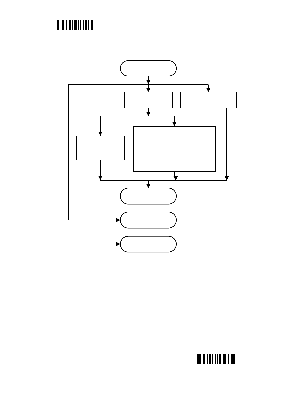
PROGRAM PROCEDURE USING SCANNER MENUS:
Page 3
SET 2/42
END
Start: Read “SET”
barcode
End: Read
“FIRMWARE” Barcode
End: Read “END”
Barcode
End: Read “SERIES
NUMBER” Barcode
When the content is“Ref. Appendix” in
the “OPTION” line, the scanner read
the barcode in the appendix. If setting
more appendix barcode, the scanner
always read this barcode, until the
system couldn’t setting.
Read the barcode in
the “OPTION” line
Read the barcode in
the “ITEM” line
Read “RESET” Barcode
1.System Information
Page 4
SET 3/42
END
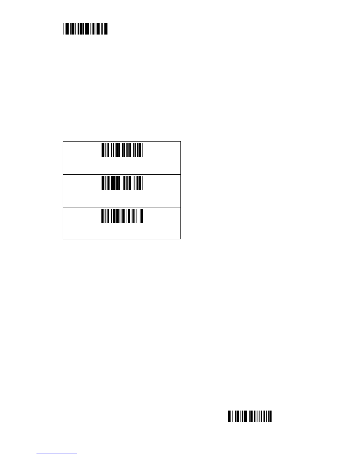
1.1 Restore default
The reading of the “RESET” label turns all the parameters back to default values.
1.2 Show firmware version
The reading of the “FIRMWARE VERSION” label will be shown firmware version.
1.3 Show series number
The reading of the “SERIES NUMBER” label will be show series number.
2. System Setup
RESET
FIRMWARE
SERIES NUMBER
Page 5
SET 4/42
END
2.1 Interface selection
There are two kinds of different interfaces to be chosen now.
The scanner remains in the last interface type when the scanner is reset.
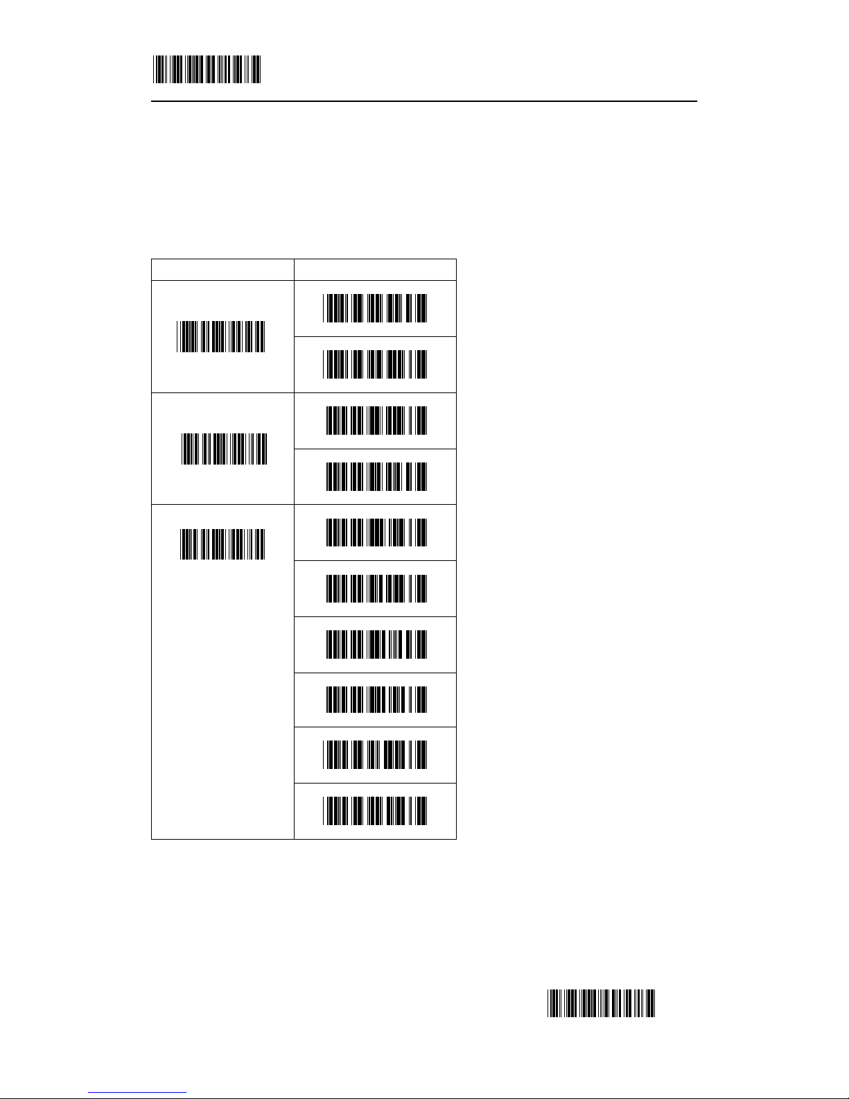
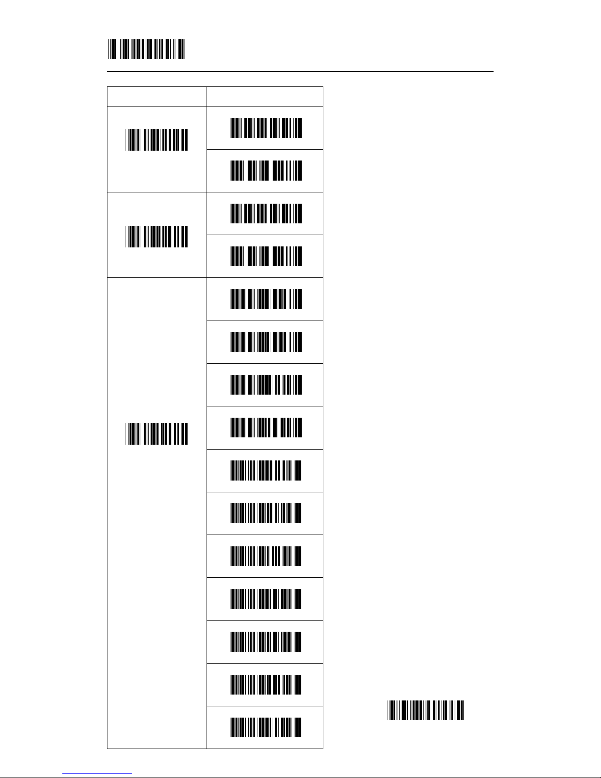
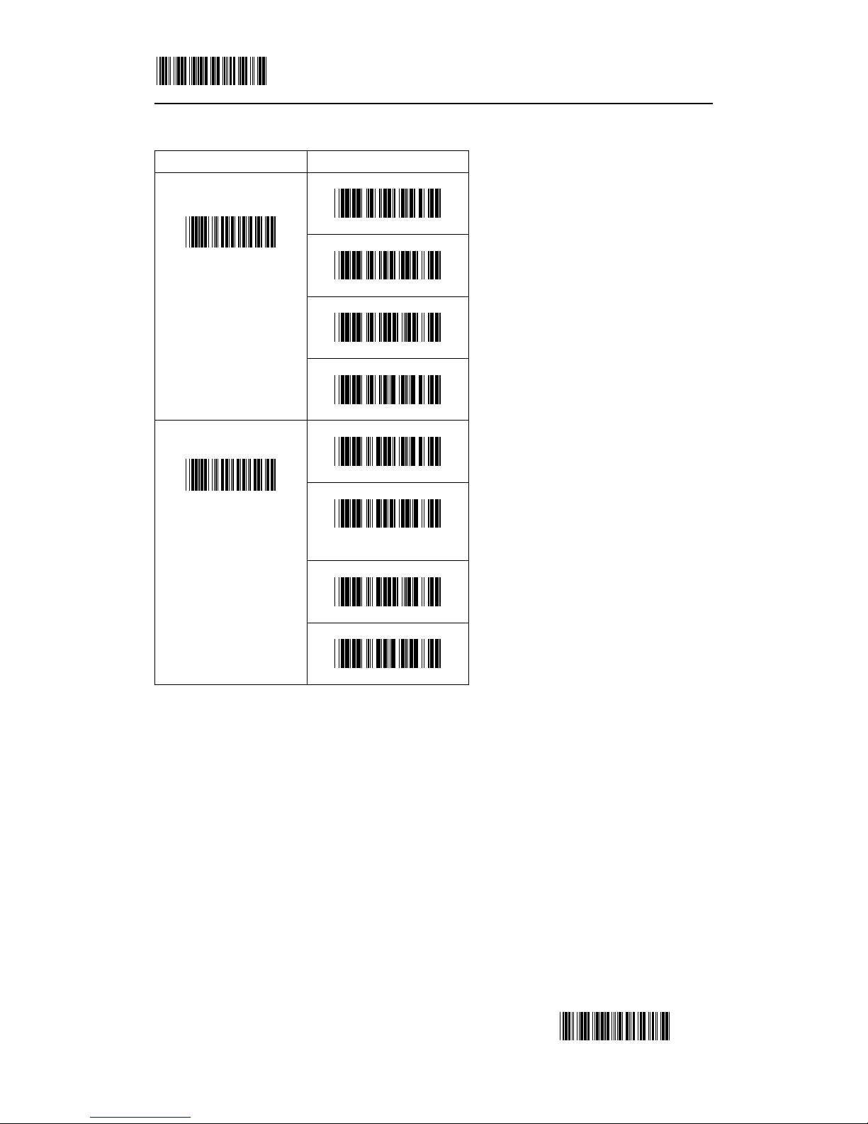
2.1.1 Keyboard emulation parameters setting
Choose the appropriate type of keyboard emulation by
scanning the labels under the following labels.
Keyboard language selection:
Function key active ON/OFF ( For IBM AT only ):
Function keys can be concatenated with input data as header and/or trailer.
ITEM OPTION
KEYBOARD ( Default )
INTERFACE
RS-232
IBM AT ( Default )
EMULATION
SELECTION
PS/2 30-80
IBM5550
IBM XT
IBM 5530-SC
IBM 5530-ZC
NEC 9801
EMULATION
SELECTION
PS/2 30,5
Page 6
SET 5/42
END
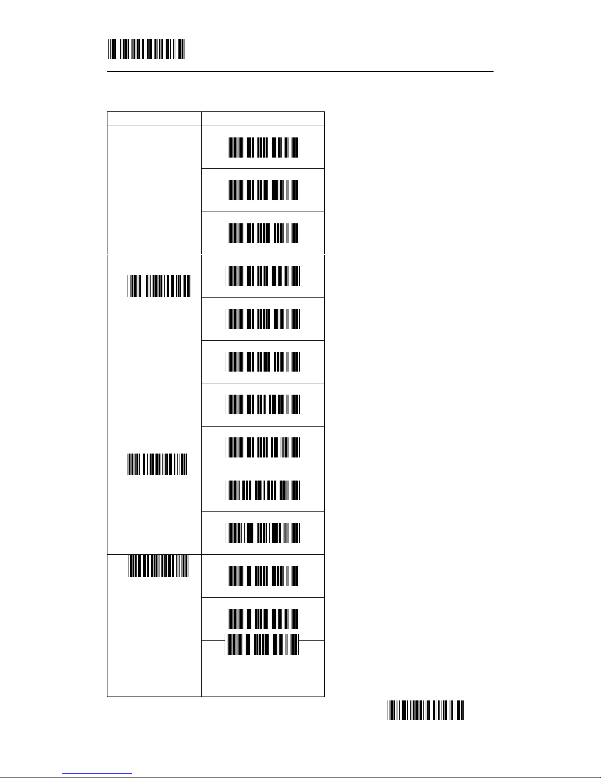
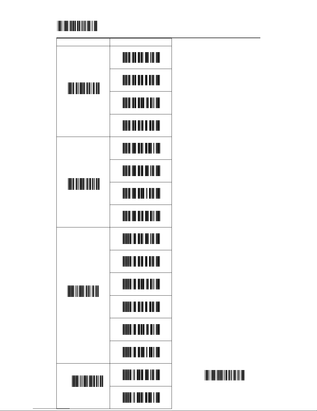
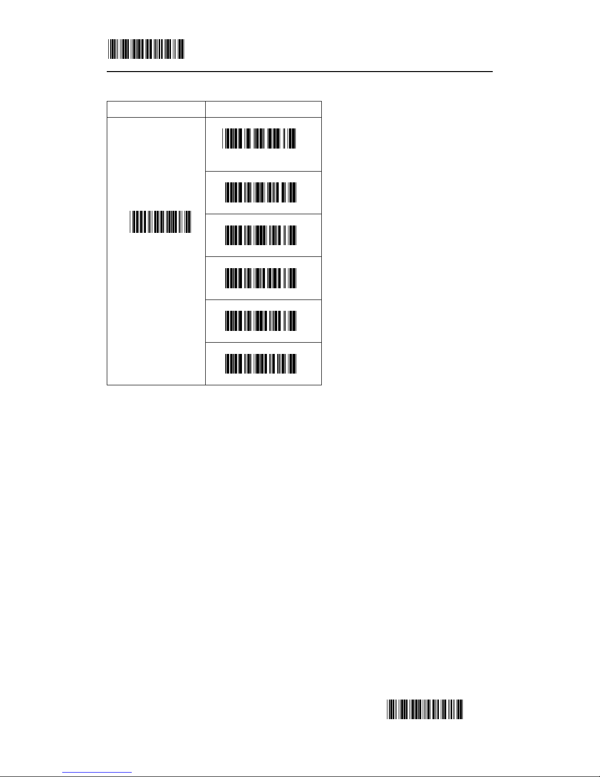
Keyboard type selection:
Capital Lock ON/OFF:
ITEM OPTION
USA ( Default )
UK
Germany
French
Spanish
Italian
Swiss
LANGUAGE
SELECTION
Swedish
OFF ( Default )
FUNCTION KEY
ON
Scan Code mode ( Default )
Alt mode
KEYBOARD TYPE
Ctrl mode
Page 7

SET 6/42
END
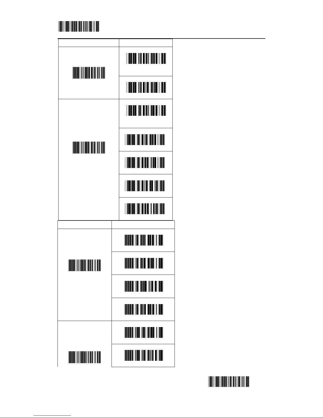
Select the suitable code to match your keyboard caps lock status.
Num Lock ON/OFF:
Inter-Character delay (for keyboard wedge):
This option governs delay time among consecutive characters.
Page 8
SET 7/42
END
Message terminator (for keyboard
wedge):
Inter-Message delay (for keyboard
wedge):
This option governs delay time between
consecutive messages.
2.1.2 RS-232 Serial communication
setting
With this option of communication
protocol, you can tailor the scanner to
meet the requirement of most systems.
ITEM OPTION
OFF ( Default )
CAPS LOCK
ON
OFF ( Default )
NUM LOCK
ON
0 ms
10 ms
20 ms
30 ms
40 ms ( Default )
50 ms
60 ms
70 ms
80 ms
90 ms
INTER-CHAR DELAY
(for KB)
100 ms
i
Page 9
SET 8/42
END
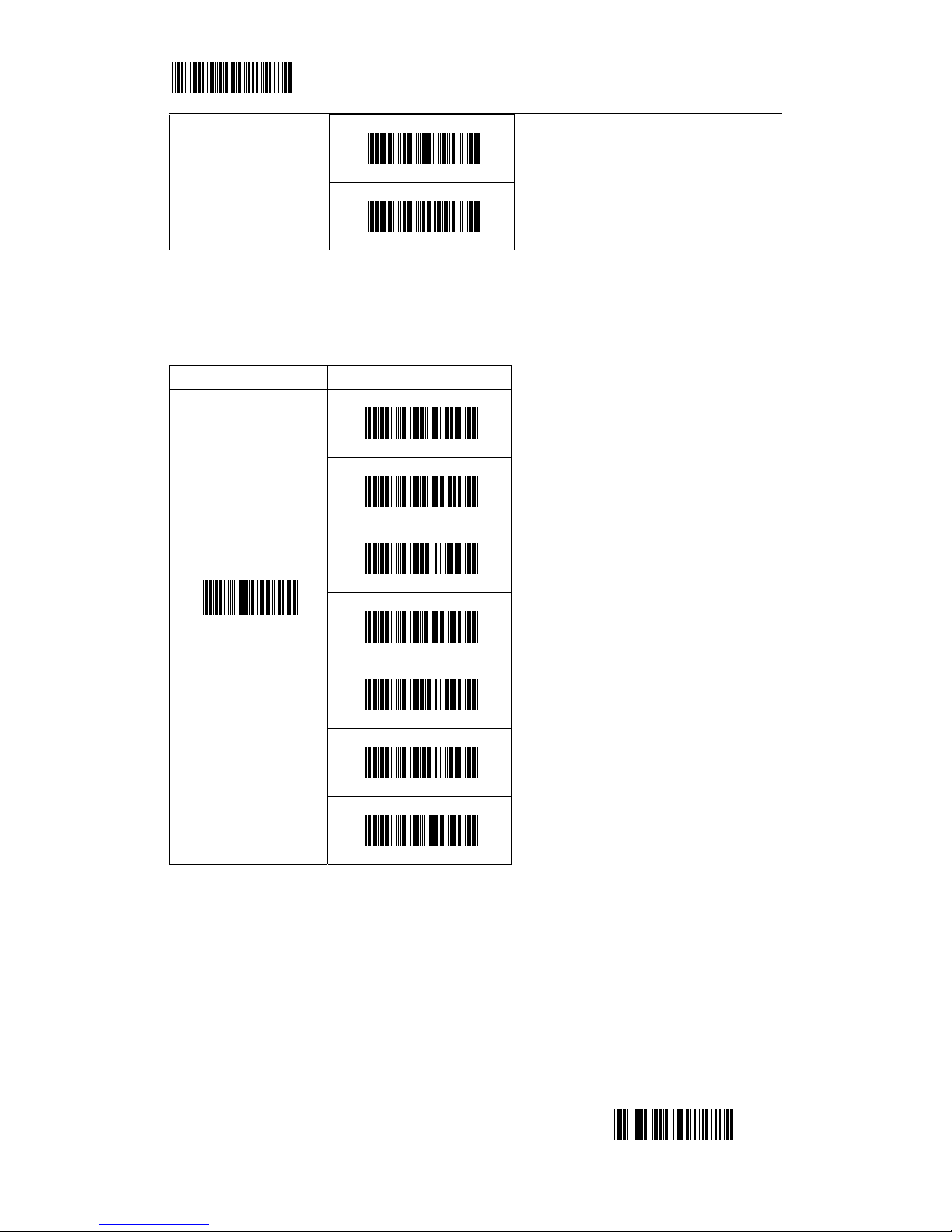
Inter-Character delay (for RS-232):
This option governs delay time between
consecutive characters.
Inter-Message delay (for RS-232):
ITEM OPTION
None
Enter ( Default )
Tab
MESSAGE
TERMINATOR
(for KB)
Execute
0 ms ( Default )
100 ms
500 ms
INTER-MESSAGE
DELAY
(for KB)
1000 ms
600 bps
1200 bps
2400 bps
4800 bps
9600 bps ( Default )
BAUD RATE
19200 bps
7 Bits
DATA BIT
8 Bits ( Default )
Page 10
SET 9/42
END
ITEM OPTION
0 ms ( Default )
10 ms
50 ms
INTER-CHARACTER
DEL AY
(for RS-232)
100 ms
0 ms ( Default )
100 ms
ITEM OPTION
1
( Default )
STOP BIT
2
None
( Default )
Even
Odd
Mark
PARITY
Space
Page 11
SET 10/42
END
500 ms
INTER-MESSAGE
DELAY
(for RS-232)
1000 ms
Message terminator ( For RS-232 ):
Handshaking protocol:
The RS-232 scanner supports four handshaking protocols.
ACK/NAK response time setting:
ITEM OPTION
None
CR/LF ( Default )
CR
LF
H Tab
STX/ETX
MESSAGE
TERMINATOR
(for RS-232)
EOT
Page 12
SET 11/42
END
2.2 Scanning mode selection
Trigger mode:
The scanner becomes inactive as
soon as the data is transmitted. It must
be triggered to become active again.
Auto scan mode:
The scanner is always on, put the barcode before the scan line, decode just one time. Decode
again only when change barcode. If decode the same barcode once more, put it on the scan line,
then scan works the second time.
Alternate mode:
When press the scanner trigger switch once, this scanner will light up. Simultaneously, The
scanner decoded only once when put the barcode on the scan line. If put the barcode on the scan
line again, the scanner decoded again. Then, the scanner will turn off for next pressing.
Repeat mode:
This mode is similar to Auto scan mode, but double reading for the same barcode is
prohibited if the scanner switch is pressed.
Testing mode:
The scanner is always on. All the while, the scanner decoded and transmitted the data
when the barcode is put on scan line.
Turbo trigger mode:
When the trigger is pressed, the scanner decoded sequentially.
ITEM OPTION
None ( Default )
RTS/CTS
ACK/NAK
HANDSHAKING
SELECTION
Xon/Xoff
300 ms
800 ms
( Default )
1500 ms
RESPONSE TIME
5000 ms
Page 13
SET 12/42
END
ITEM OPTION
Trigger mode
( Default )
Auto scan mode
Alternate mode
Repeat mode
Testing mode
SCANNING MODE
SELECTION
Turbo trigger mode
Page 14

SET 13/42
END
2.3 Beeper selection:
ITEM OPTION
Very low
Low ( Default )
Medium
BEEPER TONE
High
Disable
Very short
Short
Medium
BEEPER SOUND
DURATION
Long ( Default )
Page 15

SET 14/42
END
2.4 Header and Trailer
This option allows you to append a header and/or a trailer to every message transmitted via the
serial ports or the keyboard port. There is no restriction in selecting header or trailer characters as
far as the sum of the lengths of header and trailer is not greater than 10 digits.
1. Select either header or trailer you are going to program by scanning the corresponding label
2. Scan the character you want from the enclose ASCII table to set as header or trailer.
3. Read the “SET” label to set your choice into memory.
3. Barcode parameters setting
3.1 UPC-A
ITEM OPTION
None ( Default )
HEADER
Ref. Appendix
None ( Default )
TRAILER
Ref. Appendix
ITEM OPTION
Disable
READABLE
Enable ( Default )
Disable
( Default )
IDENTIFIER CODE
Ref: Appendix
Page 16

SET 15/42
END
ITEM OPTION
Disable ( Default )
FORCE UPC-A TO
EAN-13 FORMAT
Enable
Disable
TRANSMITTING
CHECK DIGIT
Enable ( Default )
Disable
NOT TRANSMITTING
LEADING
CHARACTER
Enable ( Default )
0 ( Default )
CUT FRONT
Ref. Appendix
0 ( Default )
CUT BACK
Ref. Appendix
Page 17

SET 16/42
END
UPC- A
3.2 UPC-E
ITEM OPTION
None ( Default )
2 bits
5 bits
ADDENDUM
2 or 5 bits
ITEM OPTION
Disable
READABLE
Enable ( Default )
Page 18

SET 17/42
END
Disable ( Default )
IDENTIFIER CODE
Ref: Appendix
Disable ( Default )
FORCE UPC-E TO UPC-A
FORMAT
Enable
Disable
TRANSMITTING
CHECK DIGIT
Enable ( Default )
0 ( Default )
CUT FRONT
Ref. Appendix
0 ( Default )
CUT BACK
Ref. Appendix
Page 19

SET 18/42
END
UPC-E
3.3 EAN-13
Disable
NOT
TRANSMITTING
LEADING
CHARACTER
Enable ( Default )
None ( Default )
2 Bits
5 Bits
ADDENDUM
2 or 5 Bits
ITEM OPTION
Disable
READABLE
Enable ( Default )
Disable ( Default )
IDENTIFIER CODE
Ref: Appendix
Disable
TRANSMITTING
CHECK DIGIT
Enable ( Default )
0 ( Default )
CUT FRONT
Ref. Appendix
Page 20

SET 19/42
END
EAN- 13
EAN-13 transfer to ISBN/ISSN
ITEM OPTION
0
( Default )
CUT BACK
Ref. Appendix
None
( Default )
2 Bits
5 Bits
ADDENDUM
2 or 5 Bits
Disable
( Default )
TRANSFER TO ISBN/ISSN
Enable
Page 21

SET 20/42
END
3.4 EAN-8
ITEM OPTION
Disable
READABLE
Enable
( Default )
Disable
( Default )
IDENTIFIER CODE
Ref: Appendix
Disable
TRANSMITTING
CHECK DIGIT
Enable
( Default )
0
( Default )
CUT FRONT
Ref. Appendix
0
( Default )
CUT BACK
Ref. Appendix
None
( Default )
2 Bits
5 Bits
ADDENDUM
2 or 5 Bits
Page 22

SET 21/42
END
3.5 Code 39
ITEM OPTION
Disable
READABLE
Enable
( Default )
Parameters setting:
ITEM OPTION
Disable
( Default )
IDENTIFIER CODE
Ref: Appendix
Disable
( Default )
CALCULATING
Enable
Disable
TRANSMITTING
CHECK DIGIT
Enable
( Default )
Disable
( Default )
CONCATENATION
Enable
0
MIN
Ref. Appendix (0~64)
( Default 0 )
Page 23

SET 22/42
END
It is possible, if using Code 39's "Full ASCII Mode" to encode all 128 ASCII characters.
3.6 Codabar
ITEM OPTION
0
MAX
Ref. Appendix (00~64)
( Default 32 )
Standard ( Default )
PARAMETERS
Full ASCII
Disable ( Default )
START/STOP
CHARACTER
TRANSMISSION
Enable
ITEM OPTION
Disable
READABLE
Enable( Default )
Disable ( Default )
IDENTIFIER CODE
Ref: Appendix
0
MAX
Ref. Appendix (0~64)
( Default 32 )
Page 24

SET 23/42
END
ITEM OPTION
Disable( Default )
CALCULATING
Enable
Disable
TRANSMITTING
CHECK DIGIT
Enable ( Default )
0 ( Default )
CUT FRONT
Ref: Appendix
0 ( Default )
CUT BACK
Ref: Appendix
ABCD/ABCD ( Default )
abcd/abcd
START/STOP
CHARACTER TYPE
abcd/tn*e
Disable ( Default )
START/STOP
CHARACTER
TRANSMISSION
Enable
0
MIN
Ref. Appendix (0~64)
( Default 0 )
Page 25

SET 24/42
END
3.7 Code 93
ITEM OPTION
Disable
READABLE
Enable (Default )
Disable ( Default )
IDENTIFIER CODE
Ref. Appendix
Disable ( Default )
CALCULATING
Enable
Disable
TRANSMITTING
CHECK DIGIT
Enable ( Default )
0
MIN
Ref. Appendix (0~64)
(Default 0)
0
MAX
Ref. Appendix (0~64)
(Default 32)
0 ( Default )
CUT FRONT
Ref: Appendix
0 ( Default )
CUT BACK Ref: Appendix
Page 26

SET 25/42
END
3.8 Code 128
ITEM OPTION
Disable
READABLE
Enable( Default )
Disable ( Default )
IDENTIFIER CODE
Ref: Appendix
Disable ( Default )
CALCULATING
Enable
Disable
TRANSMITTING
CHECK DIGIT
Enable ( Default )
Disable ( Default )
FNC2 CONCATENATION
Enable
Disable (Default )
UCC/EAN 128
Enable
Disable
FNC1 TRANSMITTED
Enable ( Default )
Page 27

SET 26/42
END
Code 128
ITEM OPTION
0
( Default )
CUT FRONT
Ref. Appendix
0
( Default )
CUT BACK
Ref. Appendix
0
MIN
Ref. Appendix (0~64)
( Default 0 )
0
MAX
Ref. Appendix (0~64)
( Default 32 )
Page 28

SET 27/42
END
3.9 Interleaved 2 of 5
ITEM OPTION
Disable
READABLE
Enable ( Default )
Disable ( Default )
IDENTIFIER CODE
Ref. Appendix
Disable ( Default )
CALCULATING
Enable
Disable
TRANSMITTING
CHECK DIGIT
Enable ( Default )
0 ( Default )
CUT FRONT
Ref. Appendix
0 ( Default )
CUT BACK
Ref. Appendix
0
MIN
Ref. Appendix (0~64)
( Default 0 )
0
MAX
Ref. Appendix (0~64)
( Default 32 )
Page 29

SET 28/42
END
3.10 Industrial 2 of 5
0 ( Default )
CUT FRONT
Ref. Appendix
0 ( Default )
CUT BACK
Ref. Appendix
ITEM OPTION
Disable
READABLE
Enable ( Default )
Disable ( Default )
IDENTIFIER CODE
Ref. Appendix
0
MIN
Ref. Appendix (0~64)
( Default 0 )
0
MAX
Ref. Appendix (0~64)
( Default 32 )
Page 30

SET 29/42
END
3.11 Standard 2 of 5
ITEM OPTION
Disable (Default)
READABLE
Enable
Disable ( Default )
IDENTIFIER CODE
Ref. Appendix
0 ( Default )
CUT FRONT
Ref. Appendix
0 ( Default )
CUT BACK
Ref. Appendix
0
MIN
Ref. Appendix (0~64)
( Default 0 )
0
MAX
Ref. Appendix (0~64)
( Default 32 )
Page 31

SET 30/42
END
3.12 Matrix 2 of 5
ITEM OPTION
Disable ( Default )
READABLE
Enable
Disable ( Default )
IDENTIFIER CODE
Ref. Appendix
Disable ( Default )
CALCULATING
Enable
Disable
TRANSMITTING
Enable ( Default )
0 ( Default )
CUT FRONT
Ref. Appendix
0 ( Default )
CUT BACK
Ref. Appendix
0
MIN
Ref. Appendix (0~64)
(Default 0)
0
MAX
Ref. Appendix (0~64)
(Default 32)
Page 32

SET 31/42
END
3.13 MSI/Plessey
ITEM OPTION
Disable ( Default )
READABLE
Enable
Disable ( Default )
IDENTIFIER CODE
Ref. Appendix
Calculate 2 bits
But not transmit
CHECK DIGIT
Not calculate ( Default )
Calculate 2 bits
Transmit 1 bit
Calculate 2 bits
Transmit 2 bits
Calculate 1 bit
But not transmit
Calculate 1 bit
Transmit 1 bit
Calculate and Transmit
CHECK DIGIT
Calculate but not transmit
Page 33

SET 32/42
END
MSI/Plessey
ITEM OPTION
0 ( Default )
CUT FRONT
Ref. Appendix
0 ( Default )
CUT BACK
Ref. Appendix
0
MIN
Ref. Appendix (0~64)
( Default 0 )
0
MAX
Ref. Appendix (0~64)
( Default 32 )
Page 34

SET 33/42
END
APPENDIX
CODE 39 FULL ASCII BAR CODE TABLE
NUL
ACK
SOH
BEL
STX
BS
ETX
HT
EOT
LF
ENQ
j
Page 35

SET 34/42
END
VT
DC2
FF
DC3
CR
DC4
SO
NAK
SI
SYN
DLE
ETB
DC1
Page 36

SET 35/42
END
CAN
US
EM
SP
SUB
!
ESC
“
FS
#
GS
$
RS
Page 37

SET 36/42
END
%
,
&
-
′
.
(
/
)
0
*
1
+
Page 38

SET 37/42
END
2
9
3
:
4
;
5
<
6
=
7
>
8
Page 39

SET 38/42
END
?
F
@
G
A
H
B
I
C
J
D
K
E
Page 40

SET 39/42
END
L
S
M
T
N
U
O
V
P
W
Q
X
R
Page 41

SET 40/42
END
Y
`
Z
a
[
b
\
c
]
d
^
e
_
Page 42

SET 41/42
END
f
m
g
n
h
o
i
p
j
q
k
r
l
Page 43

SET 42/42
END
s
z
t
{
u
|
v
}
w
~
x
DEL
y
 Loading...