

Page 1
Operating
C00269
Instructions
1
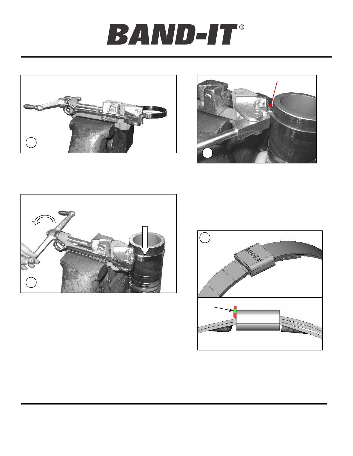
Place BAND-IT tool in vise. Insert clamp in tool and
grip end of band by Band Gripper Lever. NOTE:
The spring load of the band gripper is not
intended to secure and prevent the band from
slipping during the tension process.
2
Insert hose in clamp. Take up clamp by turning the
handle of BAND-IT TOOL clockwise while holding
band gripper tight against band. To feel movement of
band, place finger on BAND-IT BAND at buckle edge
(shown by arrow) while tensioning with tool handle.
When you no longer feel band moving through
buckle, MAXIMUM PRESSURE HAS BEEN
EXERTED BY BAND-IT BAND.
NOTE: USE OF VISE IS OPTIONAL
FOR BAND WIDTHS OF ½” OR
LESS. WE STRONGLY SUGGEST
SECURING THE TOOL IN A VISE
FOR CLAMPS WIDER THAN ½”.
To Install a BAND-IT Junior Clamp:
JR. Hand Tool
B
3
A. Roll hose over approximately 30°,
BACKING OFF TENSION HANDLE ½ to 1
turn only through course of rollover,
depending on type and size of hose.
B. Grip buckle with hook in nose by
pushing cutter handle. Push cutter handle
farther to cut the band completing BANDIT JR. Clamp.
4
CORRECT
The finished BAND-IT JR. Smooth I.D. Clamp.
Lip lock will be bent upward 90° and have a
cut-off edge (shown in green) that is flush to
the edge of the buckle. Edges shown in red
are too high or too low and may result in lower
lock strength or sharp edges.
BAND-IT-IDEX, Inc.
A Unit of IDEX Corporation
4799 Dahlia Street
Denver, CO 80216-3070 USA
P: 1-800-525-0758
F: 1-800-624-3925
www.BAND-IT-IDEX.com
Page 1 of 3
Document # P45087 Rev. I
© Copyright
BAND-IT-IDEX, Inc. 2012
All rights reserved
Page 2
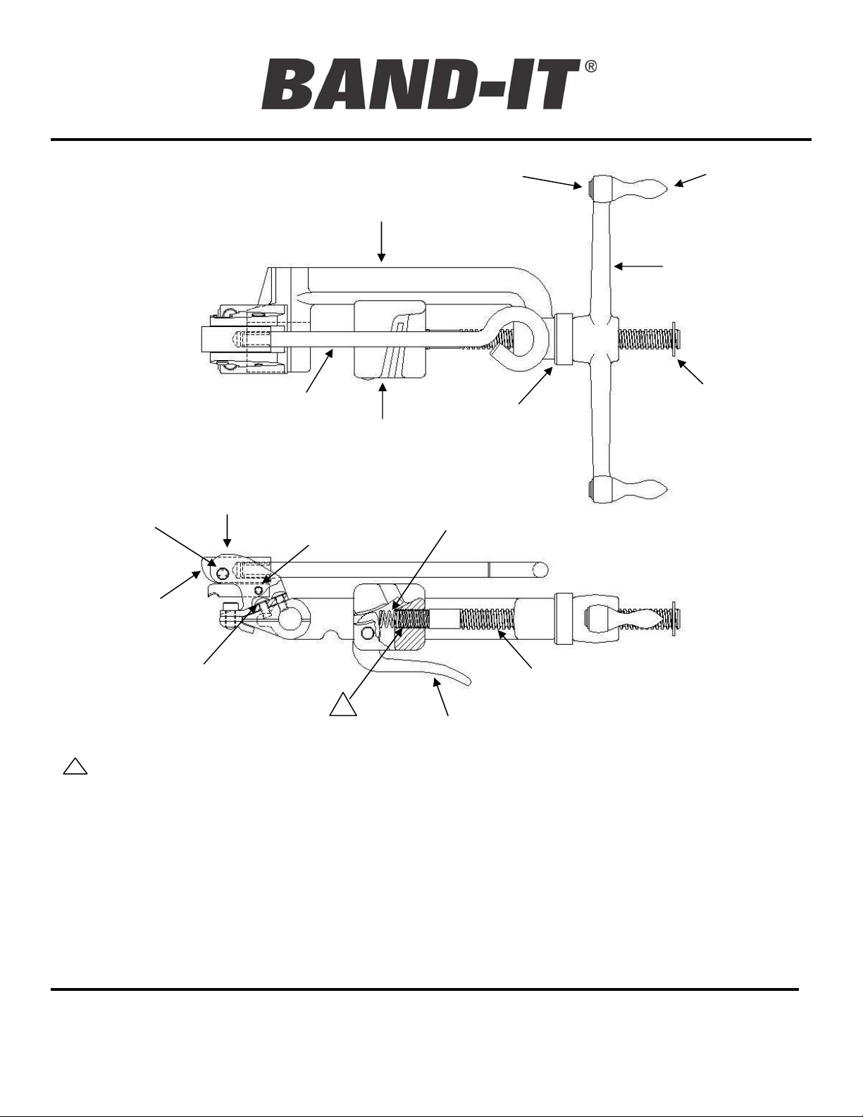
Repair Parts &
C00269
Assembly
JR. ADAPTER
PIVOT PIN
CUTTER BAR HANDLE
JR. ADAPTER BODY
HOOK PIVOT PIN
EXTERNAL RETAINING RING
TOOL FRAME
SLIDE BLOCK
JR. Hand Tool
SPIN GRIP
TENSION HANDLE
SCREW RETAINING RING
THRUST BEARING
GRIPPER SPRING
JR. ADAPTER CAM
BUTTON
HEAD SCREW
1
NOTES:
1. To assist in removing threaded parts, apply heat (softens locking compound).
2. When connecting the tension screw to the slide block, or button head screws to the JR. adapter body, clean threads
(male and female) of foreign matter, then apply two drops of medium strength locking compound (Loctite 242 or equiv.)
onto male threads and connect parts together.
3. Before using BAND-IT JR. tool check to see that the cutter blade and backing plate are fully tightened. Loose screws
can cause breakage of cutter blade or backing plate. Use hex key provided with tool to tighten screws if needed.
4. Assemble tension handle, then attach retaining ring to tension screw in location shown. Place ring on groove, then
push ring against a hard surface such as a table until it snaps securely in place.
5. Kit # C01899 contains one each of a C01887 band gripper, C03186 gripper spring and C01787 pin. Replace all parts
as a set to maximize tool performance. Periodic cleaning of band gripper teeth will improve tool performance.
BAND-IT-IDEX, Inc.
A Unit of IDEX Corporation
4799 Dahlia Street
Denver, CO 80216-3070 USA
P: 1-800-525-0758
F: 1-800-624-3925
www.BAND-IT-IDEX.com
BAND GRIPPER
Page 2 of 3
TENSION SCREW
Document # P45087 Rev. I
BAND-IT-IDEX, Inc. 2012
All rights reserved
© Copyright
Page 3

Repair Parts &
Assembly
REPAIR PARTS LIST FOR C00269
C00269
JR. Hand Tool
PART # DESCRIPTION
C02240 TOOL FRAME
C01687 THRUST BEARING
C01387 SLIDE BLOCK
TENSION HANDLE AND SCREW KIT
C00689
C01899
J01499
J02299
J93099*
J00587 SHEAR HOOK (DESIGN MAY VARY)
J00987 HOOK PIVOT PIN
S48087 SCREW, BUTTON HD. #10-32 X 3/8 L
J01387 HEX KEY, 3/16” SPECIAL LENGTH
INCLUDES: SPIN GRIP, EXTERNAL
RETAINING RING, SCREW RETAINING RING,
AND TENSION HANDLE
GRIPPER ASSEMBLY KIT
INCLUDES: GRIPPER, PIN, AND GRIPPER
SPRING
HANDLE ASSEMBLY, JR. ADAPTER
INCLUDES: JR. ADAPTER CAM AND HANDLE
BODY KIT, JR. ADAPTER
INCLUDES: JR. ADAPTER BODY AND CAM
PIVOT PIN
CUTTER BLADE KIT
INCLUDES: CUTTER BLADE, BACKING
PLATE, SCREWS AND HEX KEY
J93099 CUTTER BLADE KIT*
SCREWS
CUTTER BLADE
*NOTE: Replacement cutter blade kit
design may vary.
Replace all parts as a kit.
Operating Tip: Keep the bolts tight
(8-14 ft-lbs.). A loose bolt may cause
cracking or premature wear of the
cutter blade and/or backing plate.
This could result in improper clamp
tensioning, locking, and cutting.
Operating Tip: Keep the leading
edges of the cutter blade and
backing plate free of metal shavings.
Metal shavings will result in clamp
tail gouging during tensioning. Clean
and hone the leading edges by
hand. Do not use power tools.
Honing should polish surfaces,
not remove material.
BACKING
PLATE
Refer to website for warranty information: http://www.band-it-idex.com/warranty.html
BAND-IT-IDEX, Inc.
A Unit of IDEX Corporation
4799 Dahlia Street
Denver, CO 80216-3070 USA
P: 1-800-525-0758
F: 1-800-624-3925
www.BAND-IT-IDEX.com
Page 3 of 3
Document # P45087 Rev. I
BAND-IT-IDEX, Inc. 2012
© Copyright
All rights reserved
 Loading...