

Page 1
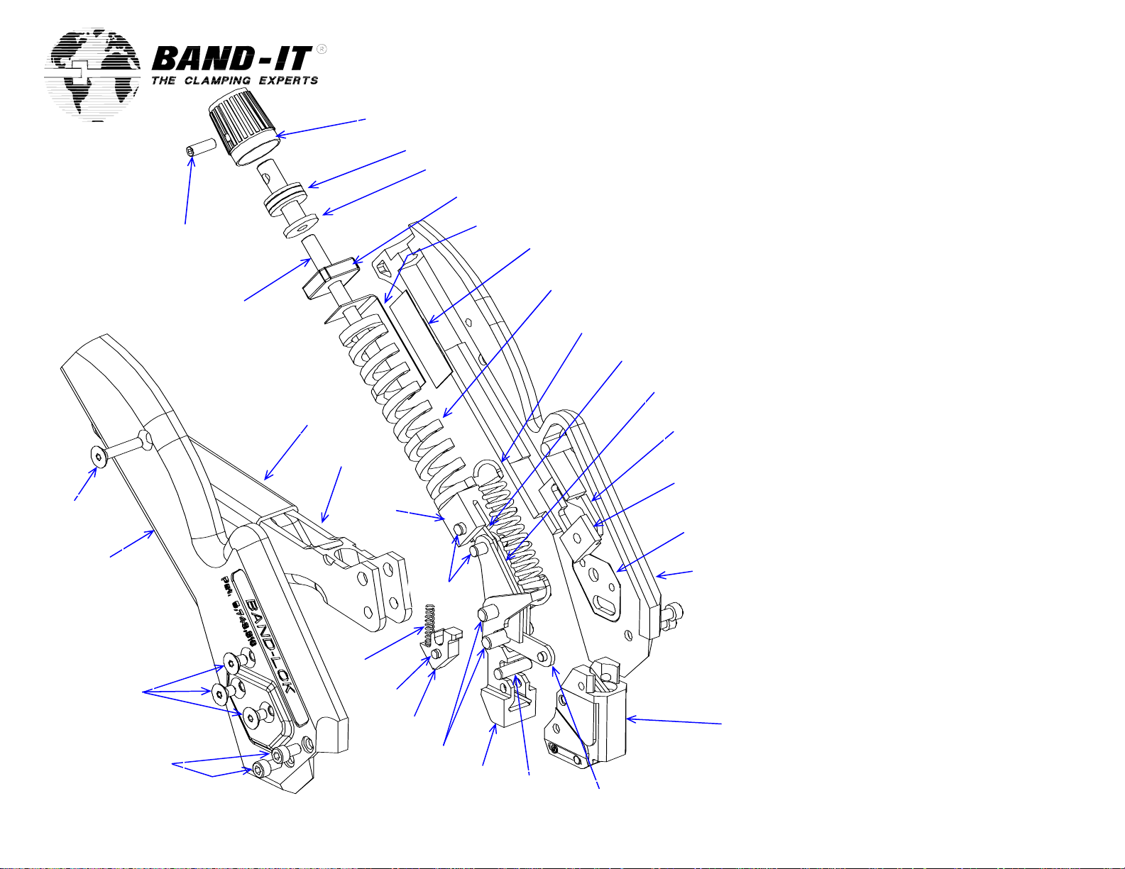
Repair Parts List
A95079 Band-Lok Tool
21
19
1
2
3
4
5
6
7, 31
8
9
10 x 2
11 x 2
29 x 2
20 25, 33
13 x 2
12
14, 31
18, 31 27 x 2, 33
17
16, 31
15
14, 31
Cut-off link and pin shown as
a reference from reverse side
Item Band-It # Qty Description
1 M53387 1 Knob, adjustment
2 M53287 1 Bearing, thrust (3 pieces)
3 A92577 1 Cap, tension
4 A93487 1 Block, tension
5 A93587 1 Indicator, tension
6 A92387 1 Decal, tension indicator
7 A91687 1 Spring, die
8 A91787 1 Spring, extension
9 A95487 1 Link, tension
10 A92267 2 Arm, tension
11 A95387 2 Plate, tension
12 K93487 1 Body, left, black
13 A91477 2 Plate, body
14 A73587 3 Pin, dowel, 5/32 x 9/16 lg
15 A91387 1 Lever, pull-up, front load
16 A94887 2 Pin, straight, 3/16 x .780 lg
17 A91187 1 Gripper, pull
18 K97487 1 Pin, .125 x .313 lg
19 A93887 1 Spring,1/8 x 5/8, 25#
20 A92487 1 Plunger, tension
21 K97587 1 Handle
22 M50787 1 Grip, textured, rust
23 A94488 1 Screw, set, #10-24 x 2.00 lg
24 A85687 1 Screw, set, #6-32 x 7/16 lg
25 A96087 1 Screw, flt-hd, #6-32 x 3/4 lg
26 K93587 1 Body, right, black
27 A91987 6 Screw, flt-hd, #6-32 x 1/4 lg
28 M54587 4 Screw, cap, #6-32 x 1/4 lg
29 K57887 2 Pad, centering
30 - - Adhesive, cyanoacrylate
31 - - Grease, extreme pressure
32 - - Red Loctite (high strength)
33 - - Blue Loctite (med. Strength)
See list of tool head
parts on reverse side
24, 33
23, 31, 32
22, 30
26
28 x 2, 33
A95051.doc Rev “F“ Page 1 of 3
Page 2
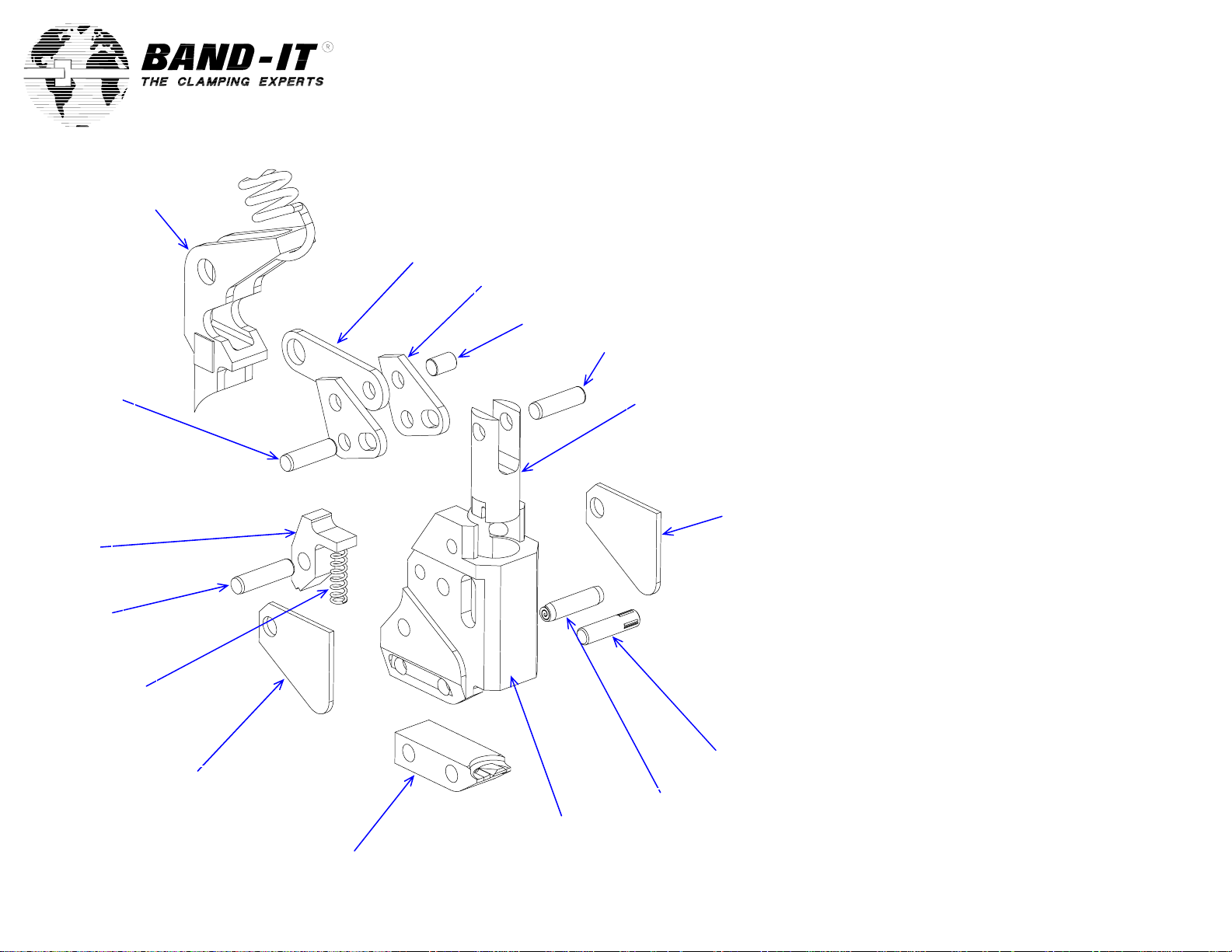
Partial view of pull-up
lever and spring shown
as a reference from
previous page
37, 47 38, 47
45
44, 47
43
39
Repair Parts List
A95079 Band-Lok Tool
34
35 x 2
36, 47
37, 47
39
40
46
41
42
Item Band-It # Qty Description
34 A92177 1 Link, cut-off
35 A94987 2 Lever, cut-off
36 A94687 1 Pin, straight, 1/8 x 3/16 lg
37 M01887 2 Pin, dowel, 1/8 x 7/16 lg
38 A96287 1 Knife, Band-Lok
39 A94187 2 Cover, head
40 A93987 1 Pin, Groove, 1/8 x 1/2 lg
41 A96187 1 Tool head
42 A96387 1 Blade, Band-Lok
43 C09587 1 Spring, 1/8 x 1/2, 13#
44 A84487 1 Pin, dowel, 1/8 x 1/2 lg
45 A91287 1 Gripper, hold
46 A90987 1 Pin, spiral, 1/8 x 1/2 lg
47 - - Grease, extreme pressure
A95051.doc Rev “F“ Page 2 of 3
Page 3

Operating Instructions
A95079 Band-Lok Tool
Warning:
Always wear safety glasses when operating
hand tool.
Instructions:
1. Turn tension adjustment knob until desired
tension setting is displayed in tension
indicator window. Space between numbers
counts as one-half setting. See step 6.
2. Extend handle open to release gripping
mechanism and insert clamp tail into tool
through front load entry.
3. Squeeze handle repeatedly to tighten band
around object. Be sure to release handle
completely to use full pull-up stroke of tool.
Buckle must be secure against the tool
head. Once the preset tension has been
reached, the handle will no longer release
completely.
4. To cut-off excess clamp tail, squeeze handle
one last time. Once the band is cut, the
handle must be released to separate the tool
from the clamp.
5. The tool must be reset by extending the
handle out until it snaps into place. The tool
will be ready to apply the next clamp.
6. Tension Setting Range:
.312 Band-Lok 0 - 8
Wrap tie around object.
Insert tail end of tie
through slot at opposite
end.
Clamp Tail
Tension
Adjustment
Knob
Tension Indicator
Window
Handle
A95051.doc Rev “F“ Page 3 of 3
 Loading...