

Page 1
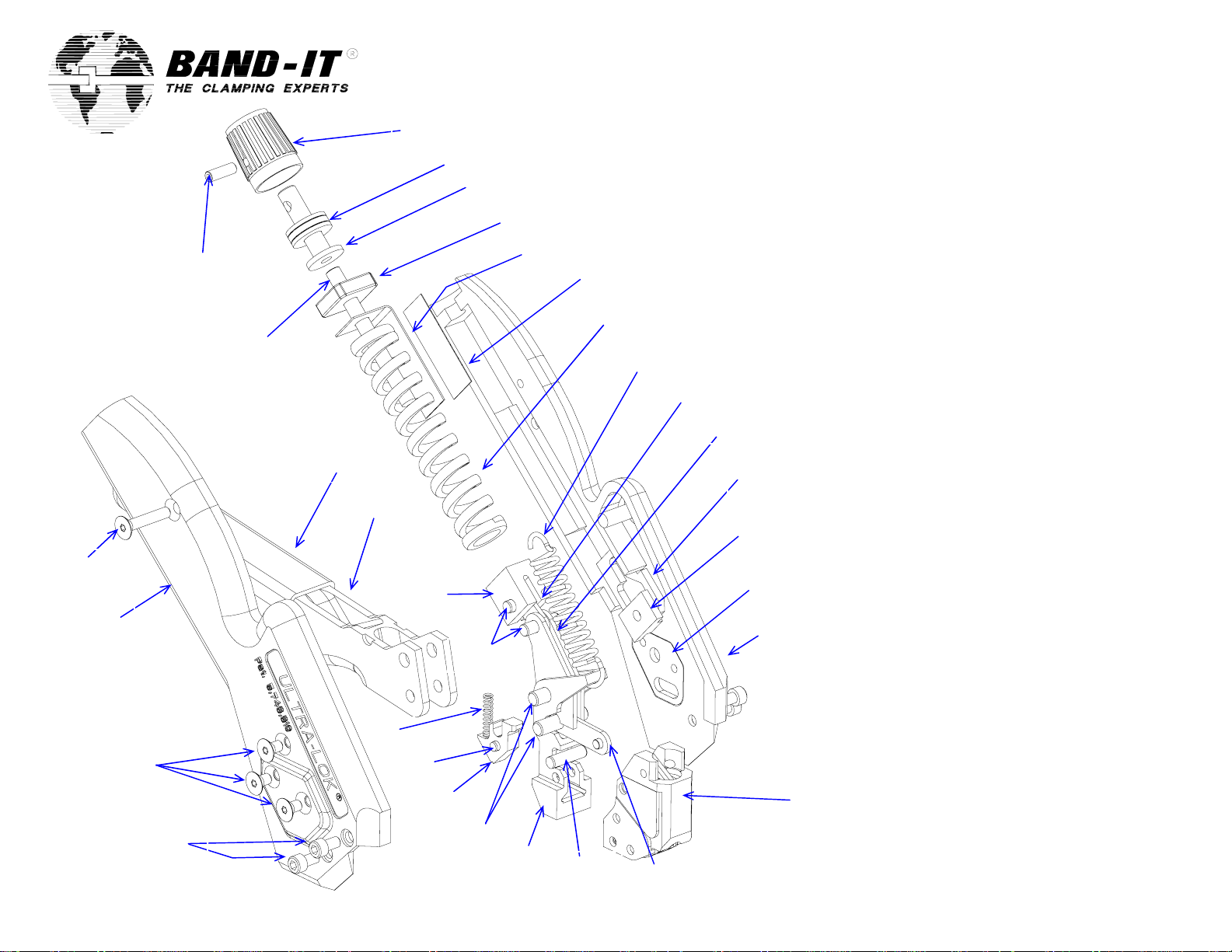
Repair Parts List
A94079 Ultra-Lok Tool
1
25, 34
26
27 x 2, 34
28 x 2, 34
A94051.doc Rev “G“
24, 34
23, 32, 33
22, 31
21
19
18, 32
20
2
17
16, 32
3
14, 32
Item Band-It # Qty Description
1 M53387 1 Knob, adjustment
2 M53287 1 Bearing, thrust (3 pieces)
4
5
6
7, 32
8
9
10 x 2
11 x 2
29 x 2
13 x 2
12
15
14, 32
Cut-off link and pin shown as
a reference from reverse side
3 A92577 1 Cap, tension
4 A93487 1 Block, tension
5 A93587 1 Indicator, tension
6 A92387 1 Decal, tension indicator
7 K02187 1 Spring, die
8 A91787 1 Spring, extension
9 A95487 1 Link, tension
10 A92267 2 Arm, tension
11 A95387 2 Plate, tension
12 K93487 1 Body, left, black
13 A91477 2 Plate, body
14 A73587 3 Pin, dowel, 5/32 x 9/16 lg
15 A91387 1 Lever, pull-up, front load
16 A94887 2 Pin, straight, 3/16 x .780 lg
17 A91187 1 Gripper, pull
18 K97487 1 Pin, .125 x .313 lg
19 A93887 1 Spring,1/8 x 5/8, 25#
20 A92487 1 Plunger, tension
21 K97587 1 Handle
22 M50487 1 Grip, textured, green
23 A94487 1 Screw, set, #10-24 x 2.00 lg
24 A85687 1 Screw, set, #6-32 x 7/16 lg
25 A96087 1 Screw, flt-hd, #6-32 x 3/4 lg
26 K93587 1 Body, right, black
27 A91987 6 Screw, flt-hd, #6-32 x 1/4 lg
28 M54587 4 Screw, cap, #6-32 x 1/4 lg
29 K57887 2 Pad, centering
30
31 - - Adhesive, cyanoacrylate
32 - - Grease, extreme pressure
33 - - Red Loctite (high strength)
34 - - Blue Loctite (med. Strength)
See list of tool head
parts on reverse side
Page 1 of 4
Page 2
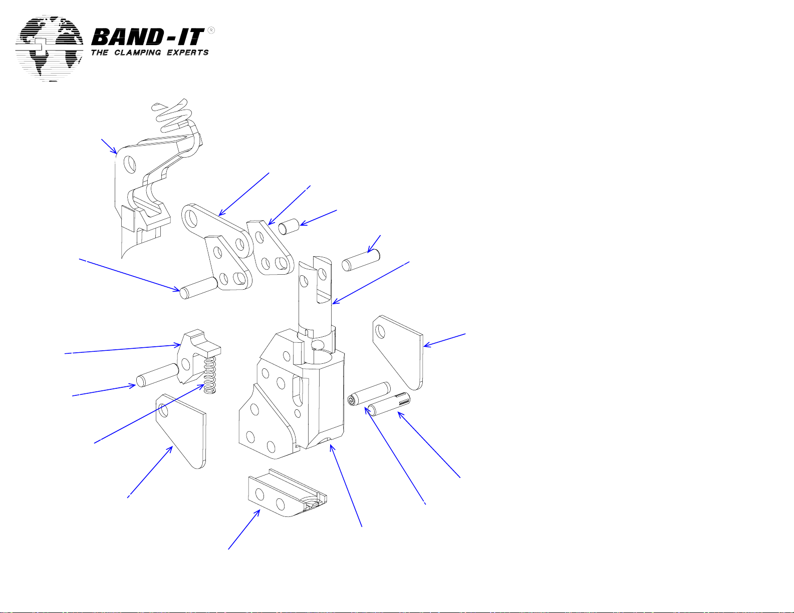
Partial view of pull-up
lever and spring shown
as a reference from
previous page
38, 48 39, 48
46
45, 48
44
40
Repair Parts List
A94079 Ultra-Lok Tool
35
36 x 2
37, 48
38, 48
41
47
42
43
Item Band-It # Qty Description
35 A92177 1 Link, cut-off
36 A94987 2 Lever, cut-off
37 A94687 1 Pin, straight, 1/8 x 3/16 lg
38 M01887 2 Pin, dowel, 1/8 x 7/16 lg
39 A92987 1 Knife, Ultra-Lok
40 A94187 2 Cover, head
41 A93977 1 Pin, Groove, 1/8 x 9/16 lg
42 A92677 1 Tool head
43 A92787 1 Blade, Ultra-Lok
44 C09587 1 Spring, 1/8 x 1/2, 13#
45 A84487 1 Pin, dowel, 1/8 x 1/2 lg
46 A91287 1 Gripper, hold
47 A90987 1 Pin, spiral, 1/8 x 1/2 lg
48 - - Grease, extreme pressure
40
A94051.doc Rev “G“
Page 2 of 4
Page 3

Warning:
Always wear safety glasses when operating hand tool.
Instructions:
1. Turn tension adjustment knob until desired
tension setting is displayed in tension indicator
window. Space between numbers counts as
one-half setting. See step 6.
2. Extend handle open to release gripping
mechanism and insert clamp tail into tool
through front load entry.
3. Squeeze handle repeatedly to tighten band
around object. Be sure to release handle
completely to use full pull-up stroke of tool.
Buckle must be secure against the tool head.
Once the preset tension has been reached, the
handle will no longer release completely.
4. To cut-off excess clamp tail, squeeze handle
one last time. Once the band is cut, the handle
must be released to separate the tool from the
clamp.
5. The tool must be reset by extending the handle
out until it snaps into place. The tool will be
ready to apply the next clamp.
6. Tension Setting Range:
.250 Smooth I.D. Ultra-Lok 0 – 8
.250 Smooth I.D. Tie-Lok 0 – 8
.250 Smooth I.D. Jr. single-wrap 0 – 8
.250 BAND-IT Band and A201 Buckle 0 – 8
Operating Instructions
A94079 Ultra-Lok Tool
Tension
Adjustment
Knob
Tension Indicator
Window
Handle
A94051.doc Rev “G“
Page 3 of 4
Page 4

Operating Instructions
A94079 Ultra-Lok Tool
Roll Band Application
A. Turn adjustment knob until tension indicator is set to –0-.
B. While holding handle all the way out from tool body, insert desired length of roll band into rear of tool head.
C. Pull handle towards tool body until band is cut. Hold handle away from tool body. Pull band out from front
of tool head.
D. If making more than one clamp, repeat the above steps.
.015 x .250 wide
roll band
E. Remove band from rear of tool head.
F. Slide buckle onto band until it is up against the buckle stop formed by the tool. “BAND-IT” logo should be
opposite the protrusion on the buckle stop.
G. Slide other end of band through buckle to form a clamp.
A201 buckle
H. Repeat steps 1 through 7 on the previous pages of this instruction sheet.
I. To make another clamp after already clamping an object, do not force handle open, instead, position roll
band behind the tool head and slowly move handle away from tool body until band passes through to
desired length. Pull handle towards tool body until band is cut. Repeat E, F, G, H.
Note: if handle “snaps” out during step I, you must start over with step A.
A94051.doc Rev “G“
Page 4 of 4
 Loading...