

Page 1

Bandit 240 PB Installation and User
Guide
©2006 All rights reserved
Bandit Solutions, Inc.
Distributed by:
Detection Dynamics, Inc.
6606 N. Lamar Blvd., Suite 300
Austin, Texas 78752
(512) 453-1133 • www.cctvpros.com
Page 2
Bandit 240 PB Installation and User Guide
Safety symbols
The following symbols are used in this installation guide to indicate possibly hazardous
conditions.
Electrical Hazard—Failure to observe the danger notice may result in
electrical shock, severe bodily injury, or death.
Caution—Failure to observe the caution notice may cause injury or
significantly disrupt or impair operation of Bandit 240 PB.
Unpacking instructions
Before installing Bandit 240 PB, open the shipping box and verify you have received the
following items:
• Bandit 240 PB
• Hypak-3
• Allen wrench
• Bandit software disk
• Optional hardware you may have ordered, such as mounting kits
Compliance
Bandit 240 PB complies with the following standard for safety and operation:
International Standard IEC 839-1-3 “Alarm Systems, General Requirements,
Environmental Testing”
Environmental Safety
Bandit’s fog is harmless to adults. Nevertheless, people with the following conditions
may experience a reaction to Bandit’s fog:
• Claustrophobics
• People with strong reactions to stressful situations
• Asthmatics
Material data safety sheets are available upon request.
2
Page 3
Bandit 240 PB Installation and User Guide
Installation
Mounting
Site selection
Select a site for mounting Bandit 240 PB with the following characteristics:
• Ambient temperate between 32–122ºF. Avoid locations close to heat sources such as
radiators and stoves.
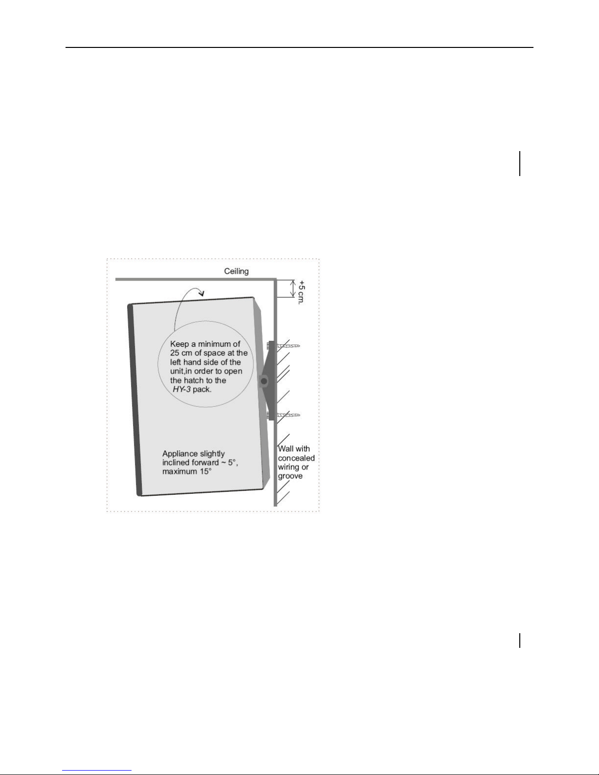
• Clearance from walls and ceiling as indicated in the following diagram. This ensures
enough room for heat dissipation and routine maintenance.
• For wall mounting, a 5º–15º inclination from vertical.
• Mount in a location away from rain or moisture.
• Mount on a wall, shelf, or floor that can support 62 lbs.
Site Selection
• Position Bandit 240 PB such that the ejection nozzle points in the direction where
intruders may enter, or in the area storing the objects you want to protect.
3
Page 4

Bandit 240 PB Installation and User Guide
• Avoid pointing the nozzle to an air circulation point, such as an open window, a
window that may be broken during a burglary, or a large circulation vent; in such
cases the nozzle may eject the fog directly outside of the protected area.
• Point the nozzle towards a wall to break the ejection pressure and allow the fog to
accumulate into a thick cloud.
• Avoid positioning the nozzle directly above an exit. This may prevent the intruder or
by-standers from leaving the protected area after an ejection.
• Avoid positioning the nozzle away from fragile objects; the force of the ejection can
topple or damage unprotected items.
• Position the nozzle such that the first surface to block the ejection is 20 feet
(6 meters) away.
• When installing multiple nozzles, position the nozzles so they expel fog in a manner
that avoids double-clouding of the same area. Suggested points are diagonally
opposite corners of a room.
Site Preparation
• Heat from Bandit’s fog ejection may trigger PIRs. Replace PIRs with combination
PIR-radar sensors that are triggered by both heat and movement; this reduces the
chances of a false alarm during fog ejection.
• Mount a motion sensor in a location that assures an intruder is detected before
approaching Bandit.
Required tools
To install Bandit 240 PB you need the following tools:
• Drill and standard set of drill bits
• Bandit Allen wrench (included in shipping box)
• Wire strippers
• Screwdrivers
• Voltage testers
• PC communications link (optional, available from Bandit Solutions, Inc.)
You may need additional hardware depending on how you install Bandit.
4
Page 5

Bandit 240 PB Installation and User Guide
Mounting procedure—wall
1. Select a mounting location. Be sure the location you select complies with the
requirements listed in the section “Site selection” on page 3.
2. If you ordered the optional Handy-Boy jig, place Bandit 240 PB on the jig.
3. Connect power wires to Bandit.
4. Mark and drill holes to ½" depth.
5. Attach the mounting plate using screws.
6. Position and secure Bandit on the mounting plate.
Proceed to “Electrical Connection” on page 6.
Mounting procedure—floor
1. Select a mounting location. Be sure the location you select complies with the
requirements listed in the section “Site selection” on page 3.
2. If you ordered the optional Handy-Boy jig, place Bandit 240 PB on the jig.
3. Connect power wires to Bandit.
4. On the floor, mark and drill holes to ½" depth.
5. Attach the mounting plate using screws.
6. Position and secure Bandit on the mounting plate.
Proceed to “Electrical Connection” on page 6.
Mounting procedure—concealed location
1. Select a mounting location. Be sure the location you select complies with the
requirements listed in the section “Site selection” on page 3. In particular, ensure you
have enough ventilation to allow heat dissipation.
2. If you ordered the optional Handy-Boy jig, place Bandit 240 PB on the jig.
3. Connect power wires to Bandit.
4. On the floor or wall, mark the location of Bandit.
5. On the door concealing Bandit, mark and drill a hole with 2" diameter.
6. On the mounting surface, mark and drill holes to ½" depth.
5
Page 6

Bandit 240 PB Installation and User Guide
7. Attach the mounting plate using screws
8. Position and secure Bandit on the mounting plate.
9. If you ordered the optional extended ejection nozzle, attach it to Bandit through the 2"
hole.
Proceed to “Electrical Connection.”
Electrical Connection
Caution—Installation of Bandit 240 PB requires a 110 VAC power source
and a dedicated ground. Be sure you follow all local safety requirements
and building codes when installing Bandit.
Refer to Figure 1 when making electrical connections.
Figure 1 - Bandit 240 PB PCB
1. Remove the real jumper to disarm fog ejection.
2. Remove power from electrical line to be connected to Bandit 240 PB.
6
Page 7

Bandit 240 PB Installation and User Guide
3. Open the rear cover on Bandit.
4. Locate the 3-way terminal block for 110 VAC power.
5. Connect power leads as follows: Red to N, black to L, and ground to ground.
6. Route power cable through strain relief.
7. Reapply power to electrical line.
8. With a volt meter, test power at N and L terminals. Verify power is 110 VAC.
9. Replace the real jumper.
Connecting Accessories
You can install accessories to Bandit 240 PB that require 12 VDC power. Examples of
accessories include the Jumbo LED or an external siren.
1. Mount the accessory.
2. Connect the red wire to the +12V power supply, and the white wire to Grdout (See
Figure 1).
3. If required, connect the blue and black wires to the Ta and Tb sabotage loop.
LEDs
The following table lists the LEDs on Bandit’s front cover and their corresponding
indications.
LED Indication
Solid green Bandit is operational.OK
Blinking green Bandit is warming up; up to 50 minutes are
required for warm up after cold start.
Guard Solid red Bandit in guard mode.
Solid red Bandit in alarm mode.Alarm
Blinking red Bandit in panic mode.
Slow blinking red Internal failure detected.Failure
Fast blinking red
HY-3 Blinking red
Technical adjustment required. Possible
causes include control box is switched on,
wrong type of HY-3 pack installed, real
jumper not plugged in (see Figure 1).
Less than 15 seconds of fog ejection time
remaining in canister. Replace or refill
canister.
7
Page 8

Bandit 240 PB Installation and User Guide
LED Indication
Power Blinking red Power supply disconnected or main fuse
blown and Bandit not in guard mode.
The following table lists the conditions of the green LED on the HY-3 Pak sleeve.
Solid green Canister installed properly and armed.
Blinking green
Fast blinking green Low fluid in canister. Replace canister.
Green off Communication failure. Clean electrical contacts, replace
Canister not installed correctly or wrong canister installed.
Replace canister.
canister, or contact Technical Support.
Maintenance
Testing fog ejection
Perform a fog ejection test once a year. To perform the test, push the test
button on the Control Box (see figure to right).
Caution— Notify all persons in test area about the test, as
well as local fire safety personnel.
Caution— Nobody in the immediate vicinity of the
nozzles or in the direct path of ejection.
Caution— During ejection do not look in the direction of
the nozzle closer than 26 feet.
Replacing HY-3 Pack
1. If installed, disarm the sabotage loop through the
Control Box.
2. Unscrew the two Allen bolts on the side hatch. Remove
the side hatch (see figure to right).
3. Unscrew the Allen bolts on the old HY-3 Pack and
remove the canister assembly.
8
Page 9

Bandit 240 PB Installation and User Guide
4. Unscrew the red Allen bolts on the canister assembly and remove the old canister.
5. Insert the new canister into the canister assembly and tighten Allen bolts.
6. Insert canister assembly into Bandit 240 PB and tighten Allen bolts.
7. Replace side hatch.
Periodic maintenance
• Clean air filter on front with a vacuum cleaner and a soft brush attachment. Clean
every six months or more frequently in dusty environments.
• Wipe dust from case every six months with a clean, damp cloth. Do not use volatile
fluids such as alcohol, thinner, or gasoline.
• Ensure no objects, such as boxes or filing cabinets, block the fog ejection path.
Specifications
Characteristic Value
Dimensions 10.6" wide × 14.4" high × 10" deep
Weight 62 pounds
Max. mains supply failure + 2 hours
Maximum reaction time 1 second between alarm signal and fog ejection
Fog ejection image Cone shaped straight ahead
Fog ejection capacity About 1,000 ft³ per second
Fog ejection pressure 232 lbf/in² (pound force per square inch)
Maximum fog ejection per pulse 18 seconds
Total fog ejection period 50 seconds
Nominal ejected droplet size 0.000001312 ft (full aerosol)
Warm-up time 50 minutes in cold settings
Max environmental temp. 122°F
Min. environmental temp. 32°F
Maximum heat loss 40W per hour
Heat exchange capacity 18,000W per hour
Capacity heating element 750W
Heating Cartridge resistance (long-life Kanthal)
Temperature sensor Platinum Pt1000 (stainless - long life)
Over temperature secured Temperature fuse
Construction material Stainless and galvanized steel
9
Page 10

Bandit 240 PB Installation and User Guide
Troubleshooting and Technical Support
Leave all repairs to authorized persons and/or the manufacturer.
For technical support, contact your distributor:
Detection Dynamics, Inc.
6606 N. Lamar Blvd., Suite 300
Austin, Texas 78752
(512) 453-1133
www.cctvpros.com
10
 Loading...