

B-ALU Extern 180, Inline 160, Inline 100, Inline 120, Inline 250 Instructions For Installation And Use Manual

Montage- und Bedienungsanleitung
Instructions for installation and use
Mode d’installation et d’emploi
Montage-en gebruiksaanwijzing
Montaggio e uso
BALU

DEUTSCH
1
So erreichen Sie uns:
Werk - Produktion
Holler Tore GmbH
Dorfstraße 31
8430 Leitring
Österreich
Tel.: +43 3452/86031-0
www.b-alu.at oder www.holler-tore.at
DEUTSCHLAND
Willering Zaun-
und Toranlagen GmbH
Dietrich-Borggreve-Str. 24
D-49828 Neuenhaus
Tel.: +49 5941 20 566 10
Fax: +49 5941 20 566 19
info@willering.de
www.willering.de
SCHWEIZ & LICHTENSTEIN
BALU Tor- und Zaunsysteme AG
Landquartstrasse 30
CH-9320 Arbon
Tel.: +41 71 558 47 47
Fax.: +41 71 558 47 45
info@b-alu.ch
www.b-alu.ch
FRANCE & BELGIEN
Peripro BV
Houtzagerijstraat 20
NL-5451 Mill
Tel.: +31 48 534 45 29
info@peripro.fr
www.peripro.fr
VEREINIGTES KÖNIGREICH
Peritect Ltd.
Lower Brimscombe Mills
Stroud Gloucestershire
GL5 2SB
Tel.: +44 14 538 83 392
office@peritect.co.uk
www.peritect.co.uk
NIEDERLANDE
Privacon Hekwerken BV
Houtzagerijstraat 20
NL-5451 Mill
Tel.: 31 48 544 23 98
info@privacon.nl
www.privacon.nl
WEST-ÖSTERREICH (TIROL)
ATT – Automatik Türen Tirol GmbH
Dorf Haus 773
6290 Mayrhofen
Tel.: 43 52 856 30 61
info@att-tirol.at
www.att-tirol.at

DEUTSCH
2
Anleitung für den Installateur und Endbenutzer
Lieber Kunde,
wir freuen uns, dass Sie sich zum Kauf unseres Tores entschlossen haben. Diese Montage- und Bedienungsanleitung enthält
sämtliche Angaben, die für das Verständnis der Funktionsweise des Produkts notwendig sind. Wir möchten Sie bitten, die
Angaben in dieser Anleitung vor Beginn der Arbeiten an diesem Produkt sorgfältig zu lesen.
Das Inhaltsverzeichnis soll Ihnen das Wiederauffinden von benötigten Angaben in der Anleitung erleichtern.
Länderspezifische Regeln und Vorschriften sind zusätzlich zu beachten!
Haftungsausschluss
Dieses Tor darf nur für das dynamische Schließen von Durchgängen benutzt werden.
Holler-Tore übernimmt keinerlei Haftung für Schäden, die durch unsachgemäße, falsche oder unbefugte Benutzung
verursacht werden. Bitte diese Anweisung vollständig lesen.
Holler-Tore verweist hinsichtlich der Fertigung der Tore auf das daran angebrachte CE-Kennzeichen.
Außerdem bieten wir Ihnen sämtliche technische Unterlagen und eine Montage- und Bedienungsanleitung.
Diese Tore entsprechen der Normvorschrift EN 13241-1. Auch für die Montage des Tors gelten bestimmte Anforderungen,
die Montageanleitung muss zu allen Zeiten beachtet werden und die Montage darf nur durch einen entsprechend
qualifizierten, fachkundigen und autorisierten BALU Installateur unter Berücksichtigung der geltenden Rechtsvorschriften
und Regelwerke ausgeführt werden. Die Sicherheit muss zu allen Zeiten gewährleistet sein, sodass Benutzer und Dritte das
Schiebetor gefahrlos bedienen können. Der Installateur ist für die einwandfreie Installation verantwortlich. Bei Rückfragen
oder Unklarheiten hinsichtlich der Montage kann sich der Installateur für weitere Auskünfte an Holler-Tore wenden.
Inhaltsverzeichnis
1. Vorsichtsmaßnahmen und Warnhinweise .................................................................................................................................................................... 3
2. Technische Spezifikation ............................................................................................................................................................................................... 4
3. Montage, Installation und Inbetriebnahme .................................................................................................................................................................. 7
4. Beschreibung der Bedienung und der Benutzung ....................................................................................................................................................... 13
5. Wartung und Instandhaltungsplan .............................................................................................................................................................................. 15
6. Umwelt, Demontage, Lagerung und Transport ........................................................................................................................................................... 16
7. Programmieranleitung ................................................................................................................................................................................................ 16
8. Anbauanleitung Verbindung 2-teilige Lieferung bei Toren über 10,5 m Pfostenlichte ................................................................................................ 23
9. Spezialanleitung BALU ECO ......................................................................................................................................................................................... 24
10. Spezialanleitung Colibri ............................................................................................................................................................................................... 25
11. Drehtor ........................................................................................................................................................................................................................ 27
12. Inline 160..................................................................................................................................................................................................................... 32
13. Konformitäts- und Leistungserklärungen .................................................................................................................................................................... 34
14. Allgemeine Liefer- und Geschäftsbedingungen .......................................................................................................................................................... 35
15. Prüfbuch für kraftbetätigte Tore ................................................................................................................................................................................. 36

DEUTSCH
3
1. Vorsichtsmaßnahmen und Warnhinweise
WICHTIGE HINWEISE:
Vor Beginn der Montagearbeiten dem Benutzer ein Montage- und Bedienungsanleitung übergeben:
Den Benutzer in die Benutzung einweisen und Tor und Säule vor Montagebeginn auf einwandfreie Funktion
kontrollieren.
Vor und während der Montage den Arbeitsbereich zur Verhinderung des unbefugten Zutritts absichern.
Die öffentliche Sicherheit den Umständen nach entsprechend berücksichtigen. Insbesondere beim Arbeiten in der Nähe
von Schulen ist die Kindersicherheit ganz besonders zu berücksichtigen.
Beim Transport von Schwerlasten immer nur zugelassene Hebewerkzeuge verwenden. Beim Ausführen von
Hebearbeiten immer mit mehr als einer Person arbeiten, auch wenn Hebehilfen benutzt werden. Das Höchstgewicht
einer von einer Einzelperson zu transportierende Last darf 25 kg nicht überschreiten.
Immer die erforderliche persönliche Schutzausrüstung tragen z.B. Schutzhandschuhe, Sicherheitsschuhe (mindestens
Klasse S3), Schutzbrille, Gehörschutz, Staubschutzmaske und Overalls.
Alle Montagearbeiten müssen von qualifizierten, sachkundigen und autorisierten BALU ausgeführt werden. Der
Installateur ist verpflichtet für den Einsatz von qualifiziertem Fachpersonal mit einschlägigen Erfahrungen zu sorgen.
Abfallstoffe sind abzusondern. Erkundigen Sie sich nach den regionalen Möglichkeiten für eine sichere und korrekte
Entsorgung.

DEUTSCH
4
2. Technische Spezifikation
2.1. Allgemeine Produktspezifikation
BALU Manuell
Abmessungen der Säule: 150 x 150 mm
BALU Inline 100
Maximale Torbreite: 10 m
Maximales Torgewicht: 700 kg
ED: 70 %
Geräuschpegel: < 80 dB (A)
Netzanschluss: 230 V
Motor-Betriebsspannung: 24 V
Abmessungen der Säule: 220 x 170 mm
BALU Inline 120
Maximale Torbreite: 12 m
Maximales Torgewicht: 1.000 kg
ED: 70 %
Geräuschpegel: < 80 dB (A)
Netzanschluss: 230 V
Motor-Betriebsspannung: 24 V
Abmessungen der Säule: 220 x 170 mm
BALU Extern 180
Maximale Torbreite: 18 m
Maximales Torgewicht: 2.000 kg
ED: 70 %
Geräuschpegel: < 80 dB (A)
Netzanschluss: 230 V
Motor-Betriebsspannung: 24 V
Abmessungen der Säule: 150 x 150 mm
BALU Inline 160
Maximale Torbreite: 16 m
Maximales Torgewicht: 1.300 kg
ED 80 %
Geräuschpegel: < 80 dB (A)
Netzanschluss: 400 V
Motor-Betriebsspannung: 400 V
Abmessungen der Säule: 220 x 170 mm
BALU Inline 250
Maximale Torbreite: 25 m
Maximales Torgewicht: 3.000 kg
ED 100 %
Geräuschpegel: < 80 dB (A)
Netzanschluss: 230 V
Motor-Betriebsspannung: 230 V
Abmessungen der Säule: 220 x 170 mm

DEUTSCH
5
2.2. Erforderliche Werkzeuge
Spaten
Kelle
Bohrer 18 mm
Bohrungsbürste
Luftpumpe
Klebepatronen M16
Inbusschlüssel 6 und 8
Wasserwaage
Steckschlüssel SW 17 und 24
Gewindestifte, Muttern &
Beilagen M16

DEUTSCH
6
2.3. Die wichtigsten Bauteile
2.3.1. Manuell
2.3.2. Inline
2.3.3. Extern
DEUTSCH
7
80 cm
3. Montage, Installation und Inbetriebnahme
3.1. Allgemeines
Vor und während der Montagearbeiten den
Arbeitsbereich zur Verhinderung des unbefugten
Zutritts absichern. Die Sicherheit von Dritten muss
gewährleistet bleiben.
Immer die erforderliche persönliche
Schutzausrüstung tragen, z.B. Schutzhandschuhe,
Sicherheitsschuhe (mindestens Klasse S3).
Schutzbrille,
Gehörschutz,
Staubmaske und
Overalls.
ACHTUNG! Alle Montagearbeiten müssen von
qualifizierten und sachkundigen Arbeitskräften
ausgeführt werden.
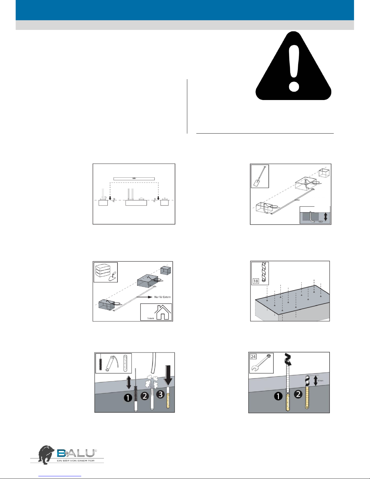
3.2. Boden vorbereiten
SCHRITT 1
Darauf achten, dass
der gesamte
Arbeitsbereich für
das Tor frei von
Hindernissen ist. Die
Platzierung auf
vorhandenem
Mauerwerk geht aus
dem Fundamentplan hervor.
SCHRITT 2
1. Kabeldurchführung und
ggf. Zubehör bereitlegen.
2. Die Nulllage des Tores
festlegen und die
Verschalung für das
Fundament herstellen.
3. Spezialkrümmer für das
Einziehen der
Leerverrohrung verwenden. Der waagrechte Teil von Krümmer und
Leerrohr muss mindestens 80 cm unter der Bodenoberfläche liegen.
SCHRITT 3
Verschalung mit
Beton füllen. Beton
bis zur vollständigen
Aushärtung und nach
Betonspezifikation
ruhen lassen.
SCHRITT 4
Jetzt die Bohrungen für
die Montage der Säule auf
dem Fundament
markieren. Für die
Bohrungen einen 18-mmBohrer verwenden.
Achtung: Bohrungen für
das Einlaufportal und die
hintere Auflaufrolle noch nicht anbringen!
SCHRITT 5
1. Bohrungen reinigen
2. mit einer
Luftpumpe Staubund Schmutzreste aus
den Bohrungen
entfernen
3. Klebepatronen
einsetzen.
SCHRITT 6
Jetzt die Gewindestifte
mit drehender Bewegung
in die Bohrungen
einsetzen. Die Enden der
Gewindestifte müssen
mindestens 60 mm über
das Fundament
hinausragen.
Die Klebeanker nach Spezifikation aushärten lassen.

DEUTSCH
8
3.3. Schiebetor platzieren
Beim Transport von Schwerlasten immer nur zugelassene
Hebewerkzeuge verwenden. Beim Ausführen von
Hebearbeiten immer mit mehr als einer Person arbeiten,
auch wenn Hebehilfen benutzt werden. Das Höchstgewicht
einer von einer Einzelperson zu hebenden Last darf 25 kg
nicht überschreiten.
ACHTUNG! Hebezeug von ausreichender Leistung benutzen.
Das Sicherheitstragvermögen ist immer auf dem Hebezeug
angegeben. Falsches Heben des Tores kann zur Verformung
des Tores führen. (Antriebssäule sichern!)
ACHTUNG! Beim Heben von Toren auf die richtige
Lastverteilung achten! Die Traggurte müssen ausreichendes
Tragvermögen haben und dürfen nicht ausgefranst sein. Für
ausreichenden Schutz des Tores sorgen! Keine Ketten
verwenden!
SCHRITT 1
1. Säule über die
Enden der
Gewindestifte
absenken.
2. Beilagen und
Muttern anbringen
und handfest
anziehen.
SCHRITT 2
1. Endanschläge nach
außen verschieben, mit
denen das Tor während
des Transportes gesichert
ist. Niemals die
Endanschläge entfernen!
2. Bei elektrischbetriebenen Toren den
Motor entsprechend Motoranleitung entriegeln.
3. Endanschläge genau in der richtigen Stellung festziehen, sodass
das Tor bündig öffnet und schließt
SCHRITT 3
Tor in den
geschlossenen
Zustand stellen.
Darauf achten, dass
der Durchgang frei
von Hindernissen
ist!
Quetschgefahr!
SCHRITT 4
Säule und Tor mit den
Muttern auf den
Gewindestäben relativ zu
Sockelplatte unter
Verwendung der
Wasserwaage lotrecht bzw.
waagerecht einnivellieren.
SCHRITT 5
Alle Muttern fest
anziehen.

DEUTSCH
9
3.4. Platzieren des Einlaufportals
SCHRITT 1
Sicherstellen, dass sich
das Tor in geschlossenem
Zustand befindet und
Position der Einlaufsäule
bestimmen.
SCHRITT 2
Die Bohrungen für das
Fundament markieren. Hierzu
die Sockelplatte als Schablone
benutzen. Tor geringfügig
öffnen. Einlaufsäule entfernen
und mit einem 18 mm Bohrer
die Bohrungen anbringen.
SCHRITT 3
1. Bohrungen mit
einer Bürste reinigen.
2. Bohrungen
säubern. Darauf
achten, dass alle
Staub- und
Schmutzrückstände
entfernt worden sind.
3. Klebepatronen einsetzen.
SCHRITT 4
Die Gewindestäbe mit
einer drehenden
Bewegung in der Bohrung
anbringen. Die Enden der
Gewindestäbe müssen
mindestens 60 mm über
das Fundament
herausragen.
Die Klebeanker nach Spezifikation aushärten lassen.
SCHRITT 5
1. Einlaufportal über die
Gewindestäbe absenken.
2. Beilagen und Muttern anbringen
und diese handfest anziehen.
SCHRITT 6
1. Tor so weit schließen,
dass die Auflaufrolle
bündig gegen die
Unterkante des
Unterholms zum Liegen
kommt (hängt vom
Tortyp ab).
2. Einlaufhöhe so
einstellen, dass der
Abstand zwischen Tor und Auflauf mindestens 5 mm beträgt. Eine
nicht einwandfreie Einstellung erhöht die Gefahr einer Störung
durch eine zu große Einlaufkraft.
SCHRITT 7
Das Einlaufportal mit
der Wasserwaage
einnivellieren und
Parallelität von Säule
und Tor kontrollieren.
SCHRITT 8
Alle Muttern fest anziehen.
DEUTSCH
10
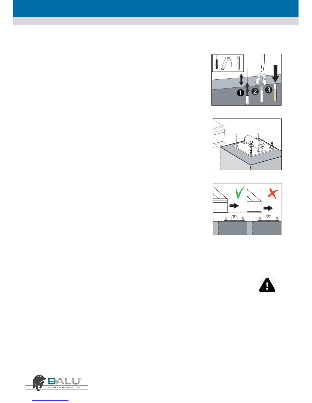
3.5. Platzieren der hinteren Auflaufrolle
SCHRITT 1
Bohrungen auf dem Fundament markieren (Position entsprechend Fundamentplan). Die
Sockelplatte als Schablone benutzen. Hintere Auflaufrolle entfernen und mit einem 18 mm
Bohrer die Bohrungen anbringen.
1. Bohrungen mit einer Bürste reinigen.
2. Bohrungen säubern. Darauf achten, dass alle Staub- und Schmutzrückstände entfernt worden
sind.
3. Klebepatronen einsetzen.
SCHRITT 2
Gewindestäbe einsetzen und Klebeanker nach Spezifikation aushärten lassen. Hintere Auflaufrolle,
Beilagen und Muttern anbringen und handfest andrehen.
SCHRITT 3
Hintere Auflaufrolle justieren. Beim Öffnen soll die hintere Auflaufrolle das Tor nicht berühren.
ACHTUNG! Das Tor darf nicht unter Zwang auf die hintere Auflaufrolle auflaufen! Ansonsten
könnte das Tor beschädigt werden.
Höhe der hinteren Auflaufrolle durch Verdrehen der Muttern einstellen. Muttern mit
Schraubenschlüssel fest anziehen.
3.6. Elektroinstallation
3.6.1. Allgemeines
ACHTUNG! Diese Montagearbeiten müssen von einem qualifizierten und sachkundigen Elektroinstallateur nach den geltenden
Regelwerken und den gesetzlichen Vorschriften ausgeführt werden.
VORSICHT! Quetschgefahr und Gefahr durch elektrischen Strom!

DEUTSCH
11
3.6.2. Inline
SCHRITT 1
Die Lichtschranken der Einlaufsäule anbringen. Den
Lichtschranken per Kabel mit dem Motor verbinden.
SCHRITT 2
Erneut kontrollieren, ob
der Endanschlag in der
korrekten Lage ist: Das
Tor muss vollständig
öffnen und schließen
können, jedoch so, dass
sich die
Sicherheitskontaktleiste
zehn Millimeter vor der Hinterseite des Auflaufs befindet.
ACHTUNG! Quetschgefahr!
SCHRITT 3
ACHTUNG!
LEBENSGEFAHR
durch elektrischen
Strom!
1. Kontrollieren, ob
die Anlage
spannungslos ist.
Danach das
Stromversorgungskabel in der Führungssäule nach den
geltenden Vorschriften an die Wandsteckdose anschließen.
2. Tor in Mittelstellung bringen.
3. In der Führungssäule den Deckel von der Steuerung
entfernen und Sicherungen prüfen.
SCHRITT 4
Warnhinweisaufkleber
anbringen
SCHRITT 5
Motor einrasten
und das Tor in die
geschlossene
Stellung fahren.
SCHRITT 6
1. Den Netzstecker in die
Wandsteckdose stecken.
2. Nach dem Schließen
des Tores die
Programmierung gemäß
der Anleitung am Motor
vornehmen.
SCHRITT 7
1. Kontrollieren, ob
alle Teile einwandfrei
funktionieren.
2. Führungssäule über
das Schloss an der
Außenseite der Säule
öffnen.
3. Stecker des Akkus in
die Steckbuchse 1
rechts oben auf der Steuerplatine stecken.
ACHTUNG! Tor funktioniert auch bei Trennung des
Netzstromes im Akku-Betrieb – Quetschgefahr – bei
Außerbetriebsetzung zusätzlich Stecker zum Akku ausstecken!

DEUTSCH
12
3.6.3. Extern
SCHRITT 1
1. Zahnstange in die
korrekte Lage zum
Motorzahnrad
einstellen. Das Spiel
muss minimal sein
(ca. 2 mm).
2. Die Einstellung der
Zahnstange relativ
zum Zahnrad über deren gesamte Länge kontrollieren.
3. Zahnstange oder Laufrollenbock nachjustieren, wenn zu viel
Spiel vorhanden ist.
SCHRITT 2
Die Lichtschranken der
Einlaufsäule anbringen.
Den Lichtschranken per
Kabel mit dem Motor
verbinden.
SCHRITT 3
Erneut
kontrollieren, ob
der Endanschlag in
der korrekten Lage
ist: Das Tor muss
vollständig öffnen
und schließen
können, jedoch so,
dass sich die
Sicherheitskontaktleiste zehn Millimeter vor der Hinterseite des
Auflaufs befindet.
ACHTUNG! Quetschgefahr!
SCHRITT 4
ACHTUNG!
LEBENSGEFAHR durch
elektrischen Strom!
1. Kontrollieren, ob die
Anlage spannungslos ist.
Danach das
Stromversorgungskabel
in der Führungssäule
nach den geltenden
Vorschriften an die Wandsteckdose anschließen.
2. Tor in Mittelstellung bringen.
3. In der Führungssäule den Deckel von der Steuerung entfernen und
Sicherungen prüfen.
SCHRITT 5
Warnhinweisaufkleber
anbringen
SCHRITT 6
Motor einrasten:
1. Den Drehknopf entgegen dem
Uhrzeigersinn bis zur vollständigen
Einkupplung drehen.
2. Die Entriegelungsknopfabdeckung
zumachen, den Schlüssel im Uhrzeigersinn
drehen und die Abdeckung über das Schloss
drehen. Der Getriebemotor ist eingekuppelt und das Tor ist
betriebsbereit.
Nachdem die Betriebsbereitschaft des Systems hergestellt worden
ist, den Schlüssel an einem sicheren Ort aufbewahren!
SCHRITT 7
1. Den
Abschaltkontakt in die
Wandsteckdose
stecken. Das Tor muss
jetzt in die
geschlossene Stellung
gefahren werden.
2. Nach dem Schließen
des Tores die
Programmierung gemäß der Anleitung am Motor vornehmen.

DEUTSCH
13
4. Beschreibung der Bedienung und der Benutzung
4.1. Allgemeines
ACHTUNG! Keinerlei Objekte zwischen die Teile des Tores stecken bzw. solche auf oder über dem Tor platzieren, während
das Tor in Bewegung ist.
Immer Abstand zum Tor halten während es in Bewegung ist!
Das Mitfahren auf dem Tor ist strengstens untersagt!
4.2. Abschaltung der Toranlage
4.2.1. Inline
SCHRITT 1
Die Säule über das
auf der Außenseite
befindliche Schloss
öffnen. Um die
Stromzufuhr zur
Torautomatik zu
unterbrechen, zuerst
den Stecker aus der
Wandsteckdose ziehen und dann den Akkuanschluss von der
Schaltplatine nehmen.
ACHTUNG! LEBENSGEFAHR durch elektrischen Strom!
SCHRITT 2
1. Verriegelung zwischen
Tor und Motor mithilfe
des
Notentriegelungshebels
am Motor lösen.
2. Das Tor ist nun von
Hand aus verstellbar.
ACHTUNG! Produkt auf
Spannungsfreiheit kontrollieren!
Beim Verstellen des Tores von Hand mögliche Quetschgefahren für
Personen, Tiere und Objekte berücksichtigen!
4.2.2. Extern
SCHRITT 1
Die Säule über das auf
der Außenseite
befindliche Schloss
öffnen. Um die
Stromzufuhr zur
Torautomatik zu
unterbrechen, zuerst
den Stecker aus der
Wandsteckdose
ziehen und dann den
Akkuanschluss von der Schaltplatine nehmen.
ACHTUNG! LEBENSGEFAHR durch elektrischen Strom!
SCHRITT 2
Entriegelungsverfahren
1. Die Schlossabdeckung drehen, den Schlüssel
einstecken, eine halbe Drehung entgegen dem
Uhrzeigersinn drehen und die
Entriegelungsknopfabdeckung aufheben. Der
Drehknopf ist nun für die Entriegelung frei.
2. Den Knopf im Uhrzeigersinn bis zum Anschlag drehen. Achtung!
Den Drehknopf nicht gewaltsam über den Endanschlag hinaus
drehen. Das Getriebe ist ausgekuppelt und das Tor kann von Hand
frei bewegt werden.
ACHTUNG! Produkt auf Spannungsfreiheit kontrollieren!
Beim Verstellen des Tores von Hand mögliche Quetschgefahren für
Personen, Tiere und Objekte berücksichtigen!
DEUTSCH
14
4.3. Einstellen des Produkts
Das Produkt nach Ihren spezifischen Gebrauchsanforderungen einstellen. So ist es beispielsweise möglich, das Tor auf voll- oder halb
automatischen Betrieb einzustellen – die Pausenzeit kann eingestellt und auch die Gehtürfunktion aktiviert werden. Angaben zu diesen
Einstellungen finden sich in der Anleitung für den Antrieb mit Steuerung.
4.4. Bedienung
Immer darauf achten, dass das Tor beim Öffnen und Schließen einwandfrei funktioniert.
Eine eingehende Beschreibung z.B. für die Programmierung der Fernbedienung findet sich in der mitgelieferten Anleitung für den Antrieb
mit Steuerung.
Achtung! Immer wenn das Tor auf die Betriebsart „Automatisches Schließen“ eingestellt ist, muss vor Aktivierung eine spezielle
Gefahrenanalyse durchgeführt werden.
Das Tor bei einer Stromstörung mithilfe des Verriegelungsgriffes am Motor entriegeln und Tor von Hand verstellen.
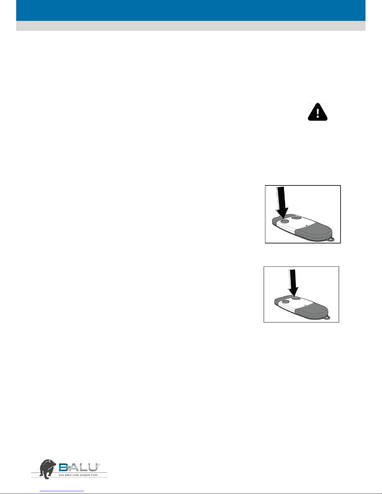
SCHRITT 1
Zum vollständigen Öffnen des Tores linken Taster der Fernbedienung benutzen. Ist die Türe auf halb
automatischen Betrieb eingestellt, muss der linke Taster auch zum Schließen des Tores benutzt
werden.
SCHRITT 2
Rechten Taster der Fernbedienung zur Gehtürfunktion benutzen. Ist die Tür auf halb automatischen
Betrieb eingestellt, muss der linke Taster auch zum Schließen des Tores benutzt werden.

DEUTSCH
15
5. Wartung und Instandhaltungsplan
5.1. Allgemeines
ACHTUNG! Diese Arbeiten müssen von einem qualifizierten und sachkundigen Techniker nach den geltenden Regelwerken und den
gesetzlichen Vorschriften ausgeführt werden.
VORSICHT! Vor der Ausführung von Instandhaltungsarbeiten an der Führungssäule und am Einlaufportal immer zuerst die
Stromversorgung abschalten.
5.2. Tägliche Wartung
Die Toröffnung zu allen Zeiten über den gesamten Fahrbereich frei von Hindernissen
halten!
5.3. Monatliche Instandhaltung
ACHTUNG! Bei der Wartung immer an die Quetschgefahr und die Möglichkeit eines elektrischen Schlages denken!
SCHRITT 1
Alle Sicherheitsvorrichtungen regelmäßig testen.
Dieses Tor ist mit verschiedenen Sicherheitsvorrichtungen ausgerüstet. Um Unfälle durch das Tor zu verhindern, müssen alle
Sicherheitsvorrichtungen regelmäßig auf einwandfreie Funktion kontrolliert werden.
• Tür in geöffnete Stellung fahren; die flache Hand gegen eine der Druckleisten drücken. Das Tor muss unverzüglich stoppen. Diesen Vorgang mit
den anderen Druckleisten wiederholen.
• Lichtschranken einmal im Monat mit einem weichen Tuch reinigen. Danach das Tor schließen und dabei mit der Hand in die Zone zwischen den
Lichtschranken reichen. Das Tor muss unverzüglich stoppen und zurückstellen.
• Die Blinkleuchte auf der Säule auf korrekte Funktion kontrollieren.
SCHRITT 2
Einmal im Monat das Innere des Unterholms reinigen. Das verhindert ein Eindringen von Schmutz in die Führung und verhindert ein Blockieren des
Tors im Betrieb.
• Hierzu das Tor in den geschlossenen Zustand fahren.
• Stromzufuhr unterbrechen.
• Mit einem Tuch den Unterholm auswischen und damit Schmutzstoffe aus dem Inneren entfernen.
• Stromzufuhr wieder einschalten und Tor auf einwandfreie Funktion kontrollieren.
5.4. Einmal im Jahr
SCHRITT 1
Sicherstellen, dass die Schiebetoranlage einmal im Jahr von hierzu befugten Fachkräften gewartet wird.
SCHRITT 2
Batterien der Sicherheitskontaktleiste an der Hauptschließkante des Tors einmal im Jahr ersetzen.

DEUTSCH
16
6. Umwelt, Demontage, Lagerung und Transport
6.1. Umweltfreundliche Demontage
Entsorgen Sie das Produkt ausschließlich über einen autorisierten Entsorgungsbetrieb!
Die Demontage darf nur durch Fachpersonal durchgeführt werden!
6.2. Lagerung und Transport
Soll das Produkt eingelagert oder transportiert werden, ist auf gute Verpackung zu achten. Die Lagerung muss in einem trockenen Raum
erfolgen.
7. Programmieranleitung
7.1. Schnell-Inbetriebnahme
Die Toranlage wird werkseitig mit den wichtigsten Voreinstellungen ausgeliefert und kann binnen weniger Minuten individualisiert werden:
Überprüfen Sie, dass vor dem Programmieren die mechanischen Anschläge in Öffnung und Schließung vorhanden und eingestellt sind. Diese
sind als Transportsicherung zum Aggregat verschoben.
ACHTUNG: Während des Lernlaufes ist die Kraftabschaltung außer Betrieb. Achten Sie deshalb darauf, dass sich während des Lernlaufes
keine Personen oder Gegenstände im Gefahrenbereich befinden. Sicherstellen, dass während des Laufens kein Start- oder Stoppbefehl
gegeben und die Lichtschranken nicht unterbrochen werden.
Buttons:
Standardanzeige bei anliegender Netzspannung
Dauerleuchten: alles OK
Blinken: Störung
Die Taste P2 „PROGR/OK“ für mindestens 4 Sekunden
gedrückt halten
2x die Taste P2 „PROG/OK“ drücken. Das Tor
öffnet bis zum internen Anschlag, überprüft diesen
und speichert ihn ab.
Das Tor schließt selbstständig bis zum internen Anschlag,
überprüft diesen nochmals und speichert ihn ab.
Die Steuerung hat somit die Endstellung und die
notwendigen Betriebskräfte abgespeichert. Blinkt
„PROGRAM“ im Display, muss die Lernfahrt erneut
gestartet werden.
INLINE 100
INLINE 120

DEUTSCH
17
7.2. Klemmenbelegung
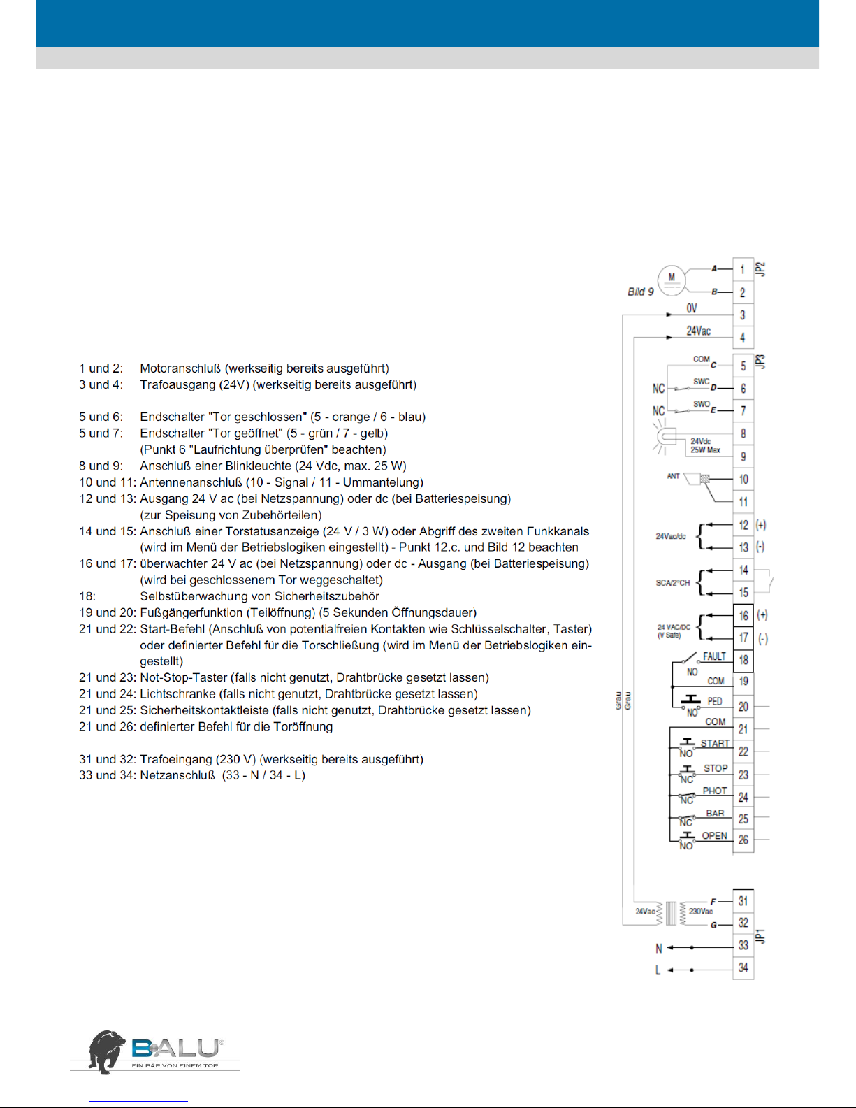
1 – 2
MOT
Motoranschluss (werksseitig ausgeführt)
3 – 6
ENC
Encoderanschluss (3 – blau / 4 – grün / 5 – grau / 6 – gelb) (werksseitig ausgeführt)
7
LCK
Notentriegelung (Anzeige auf dem Display „Motor frei“)
8
CMN
gemeinsamer Anschluss
9 – 10
LC/CH2
Anschluss eines extern versorgten Umgebungslichtes (max. 30 V ac/dc, 1A)
oder Abgriff 2. Funkkanal (potenzialfreier Schaltkontakt)
11
CMN
gemeinsamer Abschluss
12
LP
Blinkleuchten (24 V dc / max. 25 W blinkend oder 12,5 W permanent)
13
LS
Kontrollleuchte „Tor offen“ (24 V dc / max. 3 W)
blinkt langsam während der Öffnung, blinkt schnell während der Schließung
leuchtet permanent, wenn das schließende Tor blockiert wird
erlischt bei geschlossenem Tor
14
CMN
gemeinsamer Anschluss
15
CTRL24Vdc
24 V dc zur Speisung überwachter Lichtschrankensender
16
CMN
gemeinsamer Anschluss
17
OUT24Vdc
24 V dc zur Speisung von Lichtschrankenempfänger
ACHTUNG! Klemme 15 + 17 dürfen mit max. 10 W belastet werden!
18
TA
definierter Öffnungsbefehl
19
TC
definierter Schließbefehl
20
TAL
Teilöffnung (1-9 m programmierbar)
21
TD
dynamischer Startimpuls
Öffnung mit Impulsblockierung bis Tor geöffnet, Impuls bei Schließung öffnet
Öffnung – stoppen – Schließung – stoppen
22
CMN
gemeinsamer Anschluss
23
TB
Non-Stopp / Anschluss Sicherheitskontaktleiste
24
CP
reversierende Sicherheitseinrichtung / Anschluss Sicherheitskontaktleiste
25
FS
stoppender Lichtschrankenanschluss in Schließung. Nach Freigabe wir die
Schließbewegung fortgesetzt / Anschluss Sicherheitskontaktleiste
26
FI
reversierende Sicherheitseinrichtung in Schließung / Anschluss Sicherheitskontaktleiste
27
ANT
Antennenanschluss (Signal) (RG 58 / 50 Ω)
28
ANT
Antennenanschluss (Ummantelung)
29
CMN
gemeinsamer Anschluss für die Notfallbedienung
30
EMRG1
bedient das Tor in dem die Steuerung umgangen wird
sitzt der Antrieb links, wird Tor geschlossen, beim rechten Antrieb geöffnet
31
EMRG2
bedient das Tor in dem die Steuerung umgangen wird
sitzt der Antrieb links, wird Tor geöffnet, beim rechten Antrieb geschlossen

DEUTSCH
18
7.3. Zeitschaltuhr
Zeitschaltuhr 1-Kanal
CMN TA
Antrieb öffnet in der eingestellten Zeit Zwischenbewegungen mit Betriebsfunk möglich, Schließung mit Automatikschließung
CP (24) Serie mit Lichtschranke, Schließen mit Automatikschließung
Erste Öffnung mit Impuls keine Zwischenbewegung möglich
Zeitschaltuhr 2-Kanal
CMN TA
Serie mit Lichtschranke
CP (24)
Antrieb öffnet zu eingestellter Zeit, Zwischenbewegung nicht möglich (Kanal 1 + 2 gleich programmieren), Schließen mit Automatikschließung
Programmierung Zeitschaltuhr entsprechend Programmieranleitung!
7.4. Programmierung
Damit Sie Ihre Toranlage Ihren individuellen Bedürfnissen anpassen können, bietet Ihnen die Steuerung einige Funktionen und Parameter
die an- oder ausgeschaltet bzw. angepasst werden können. Das nachfolgende Schema zeigt Ihnen als Wegweiser, wie Sie zu den
gewünschten Menüpunkten gelangen.
Die hervorgehobenen Werte zeigen Ihnen die Werkeinstellung an.
7.4.1. Optionen
1 x P3 drücken – das Menü zur Einstellung von „Optionen“ öffnen
1 x P2 drücken – das Menü zur Einstellung von „Optionen“ auswählen
Untermenü Optionen - mit „PROG/OK“ die Einstellungen ändern
- mit P1 oder P3 im Menü auf- und abwärts

DEUTSCH
19
Funktion des Schlüsseltasters
DYNAMISCHE TASTE
ÖFFNEN-SCHLIESS.
ÖFFN.-STOP-SCH
Definiert die Funktion der Klemme 21 (potenzialfrei)
Öffnen
Öffnet mit Impulsblockierung
Automatische Schließung
AUTO. WIEDERSCHL.
ON
OFF
Schaltet den automatischen Zulauf an oder aus
Automatischer Zulauf nach der vorgegebenen Zeit
Automatischer Zulauf deaktiviert
Vorblinken der Blinkleuchte
VORBLINKEN
ON
OFF
Aktiviert das Vorblinken einer an Klemme 12
angeschlossenen Blinkleuchte
2-maliges Vorblinken der Blinkleuchte
Antrieb startet sofort ohne Vorblinken
Funktion der Blinkleuchte
BLINKLICHT
DAUERLEUCHTEND
BLINKEND
Definiert die Funktion der an Klemme 12
angeschlossenen Blinkleuchte
Leuchte ist durchgehend während der Bewegung an
Leuchte blinkt während der Torbewegung
Funktion der Kontrollleuchte
KONTROLLLEUCHTE
DAUERLEUCHTEND
BLINKEND
Definiert die Funktion der an Klemme 13
angeschlossenen Kontrollleuchte
Dauerleuchten der Kontrollleuchte
Blinkend wie unter „Klemmenbelegung“ beschrieben
Funktion der Lichtschranke
UMKEHR-LICHTSCH.
BEIM SCHLIESSEN
AUCH BEIM STOP
Definiert die Funktion der an Klemme 26
angeschlossenen Sicherheitseinrichtung
Bewegungsumkehr bei Ansprechen der Sicherheit
Impulse sind blockiert solange die Sicherheit aktiv ist
Überwachung der Sicherheit
TEST FI
ON
OFF
Aktiviert die Überwachung der an Klemme 26
angeschlossenen Sicherheitseinrichtung
Überwachung aktiv
Überwachung nicht aktiv
Überwachung der Sicherheit
TEST FI
ON
OFF
Aktiviert die Überwachung der an Klemme 25
angeschlossenen Sicherheitseinrichtung
Überwachung aktiv
Überwachung nicht aktiv
Motordrehrichtung
MOTOR EINBAU
LINKS
RECHTS
Definiert die Drehrichtung des Motors
Antrieb von Hofinnenseite aus links installiert
Antrieb von Hofinnenseite aus rechts installiert
Impuls- und Funkbetrieb oder Totmann
MANUELL
ON
OFF
Impulsbetrieb oder Totmannmodus
Totmann (Klemme 18/19 müssen gedrückt bleiben)
Impulsbetrieb / Selbsthaltung
Ferneinlernung von Handsender aktivieren
FUNK-SPEICHERUNG
ON
OFF
Einlernung weiterer Handsender über Funk
Einlernung über Funk aktiviert
Deaktiviert, nur über das Funkmenü möglich
2. Funkkanal oder Umgebungslicht
AUSGANG LC/CH2
FUNK-KANAL
WACHLICHT
Definiert die Funktion der Klemmen 9-10
Abgriff 2. Funkkanal
Extern versorgtes Umgebungslicht (max. 30A ac/dc,
1A)
„Optionen“ verlassen
AUSGANG
OK
Menü „Optionen“ verlassen
Durch Drücken der Taste P2 „PROG/OK“ gelangt
man wieder ins Hauptmenü zum Menüpunkt
„Optionen“

DEUTSCH
20
7.4.2. Sicherheitsvorrichtungen
2 x P3 drücken – das Menü zur Einstellung von „Sicherheitsvorrichtungen“ öffnen
1 x P2 drücken – das Menü zur Einstellung von „Sicherheitsvorrichtungen“ auswählen
Untermenü Optionen - mit „PROG/OK“ die Einstellungen ändern
- mit P1 oder P3 im Menü auf- und abwärts
KONTAKT TB
NC
8K2
Definiert die Funktion der Klemme 23
In Ruhe geschlossener Kontakt (Drahtbrücke gesetzt)
Anschluss einer Sicherheitskontaktleiste 8,2 KΩ
KONTAKT FI
NC
8K2
Definiert die Funktion der Klemme 26
In Ruhe geschlossener Kontakt (Drahtbrücke gesetzt)
Anschluss einer Sicherheitskontaktleiste 8,2 KΩ
KONTAKT FS
NC
8K2
Definiert die Funktion der Klemme 25
In Ruhe geschlossener Kontakt (Drahtbrücke gesetzt)
Anschluss einer Sicherheitskontaktleiste 8,2 KΩ
KONTAKT CP
NC
8K2
Definiert die Funktion der Klemme 24
In Ruhe geschlossener Kontakt (Drahtbrücke gesetzt)
Anschluss einer Sicherheitskontaktleiste 8,2 KΩ
AUSGANG
OK
Menü „Sicherheitsvorr.“ Verlassen
Durch Drücken der Taste P2 „PROG/OK“ gelangt man
wieder ins Hauptmenü zum Menüpunkt
„Sicherheitsvorr.“
7.4.3. Bewegung
3 x P3 drücken – das Menü zur Einstellung von „Bewegung“ öffnen
1 x P2 drücken – das Menü zur Einstellung von „Bewegung“ auswählen
Untermenü Optionen - mit „PROG/OK“ die Einstellungen ändern
- mit P1 oder P3 im Menü auf- und abwärts
MOTORAUSWAHL
i924 ESY
i924 ESB 700 kg
i924 ELB 1000 kg
Definiert den Motortyp
Ohne Funktion
Maximale Zug- und Schubkraft von 700 kg
Maximale Zug- und Schubkraft von 1000 kg
STROMSENSOR
NIVEAU 1…5
Krafteinstellung des Antriebes
Jedes Niveau erhöht die max. Stromaufnahme und somit
die Kraft des Antriebes um 1 Ampere (Niveau 1 = + 2A)
BEGRENZTE ÖFFNUNG
METER 1…9
Definiert die Annäherung an den Pfosten bei der
Schließung
Die Öffnungsweite der Fußgängerfunktion kann hier von 1
bis 9 Meter eingestellt werden.
ABSTAND SCHLIESS
0…4…9 SCHRITTE
Definiert die Annäherung an den Pfosten bei der
Schließung
In 9 Schritten kann der Abstand von 0 – 6 cm verändert
werden. Werkseinstellung ist „4“ = 1 cm Abstand
PAUSENZEIT
000…240 sec
Definiert die Dauer der automatischen Schließung
Ist der automatische Zulauf im Menü „Optionen“ aktiviert,
wird hier die Offenhaltungszeit eingestellt
PARAMETER RESET
OK
Werksdaten laden
Setzt die Steuerung auf die Werkdaten zurück. Einzig die
ausgewählte Sprache bleibt.
AUSGANG
OK
Menü „Bewegung“ verlassen
Durch Drücken der Taste P2 „PROG/OK“ gelangt man
wieder ins Hauptmenü zum Menüpunkt „Bewegung.“

DEUTSCH
21
7.4.4. Display
4 x P3 drücken – das Menü zur Einstellung von „Display“ öffnen
1 x P2 drücken – das Menü zur Einstellung von „Display“ auswählen
Untermenü Optionen - mit „PROG/OK“ die Einstellungen ändern
- mit P1 oder P3 im Menü auf- und abwärts
KONTRAST
OK
0…27…63
Einstellung des Displaykontrastes
Im Untermenü „Kontrasteinstellungen“ kann die
Helligkeit des Displays vom 0 – 63 angepasst werden
HINTERGRUND
DAUERLEUCHTEND
60 SEK / 30 SEK
Hintergrundbeleuchtung des Displays
Die Dauer der Hintergrundbeleuchtung von dem
Display kann auch 30 oder 60 Sekunden gesetzt
werden.
AUSGANG
OK
Menü „Display“ verlassen
Durch Drücken der Taste P2 „PROG/OK“ gelangt man
wieder ins Hauptmenü zum Menüpunkt „Display.“
7.4.5. Test
5 x P3 drücken – das Menü zur Einstellung von „Test“ öffnen
1 x P2 drücken – das Menü zur Einstellung von „Test“ auswählen
Durch Blinken wird angezeigt, ob eine Sicherheitseinrichtung angesprochen ist:
TB = Sicherheitseinrichtung an Klemme 23 ist angesprochen
FI = Sicherheitseinrichtung an Klemme 26 ist angesprochen
FS = Sicherheitseinrichtung an Klemme 25 ist angesprochen
CP = Sicherheitseinrichtung an Klemme 24 ist angesprochen
7.4.6. Funk
6 x P3 drücken – Menü zur Verwaltung der Handsender
1 x P2 drücken – Menüpunkt auswählen

DEUTSCH
22
Einen Handsender auf den Funkempfänger einlernen oder einzeln löschen:
SPEICHERUNG
OK
SPEICHERUNG [n…]
Aktivierung 1
Die gewünschte Taste am
Handsender drücken
SPEICHERUNG [n…]
Aktivierung 2
Zum Bestätigen die gewünschte
Taste erneut drücken
SPEICHERUNG [n…]
CODE GESPEICHERT
Die Steuerung bestätigt die
Speicherung des Handsenders
LÖSCHUNG
OK
LÖSCHUNG [n…]
Aktivierung 1
Die zu löschende Taste am
Handsender drücken
LÖSCHUNG [n…]
Aktivierung 2
Zum Bestätigen die zu löschende
Taste erneut drücken
LÖSCHUNG [n…]
CODE GESPEICHERT
Die Steuerung bestätigt die
Löschung des Handsenders
Alle Handsender aus dem Funkempfänger löschen
TOTAL LÖSCHUNG
OK
SPEICHER LÖSCH.?
OK
Mit „PROG/OK“ bestätigen das
der gesamte Funkempfänger
gelöscht werden soll
LÖSCHUNG LÄUFT
Definieren, was ein Funkbefehl bewirken soll:
KANAL-FUNKTIONEN
OK
KANAL A
BEFEHL TD/TAL/TA/TC
BLOCK/AUSGANG CH2
KEIN BEFEHL
1. Funkbefehl wirkt als dyn. Start,
Fußgängerfunktion def. Auf oder Zu,
als Stopp, 2. Funkkanal (Klemme 9 –
10)
KANAL B
BEFEHL TD/TAL/TA/TC
BLOCK/AUSGANG CH2
KEIN BEFEHL
2. Funkbefehl wirkt als dyn. Start,
Fußgängerfunktion def. Auf oder Zu,
als Stopp, 2. Funkkanal (Klemme 9 –
10)
KANAL C
BEFEHL TD/TAL/TA/TC
BLOCK/AUSGANG CH2
KEIN BEFEHL
3. Funkbefehl wirkt als dyn. Start,
Fußgängerfunktion def. Auf oder Zu,
als Stopp, 2. Funkkanal (Klemme 9 –
10)
KANAL D
BEFEHL TD/TAL/TA/TC
BLOCK/AUSGANG CH2
KEIN BEFEHL
4. Funkbefehl wirkt als dyn. Start,
Fußgängerfunktion def. Auf oder Zu,
als Stopp, 2. Funkkanal (Klemme 9 –
10)

DEUTSCH
23
8. Anbauanleitung Verbindung 2-teilige Lieferung bei Toren über 10,5 m
Pfostenlichte
Achtung! Kürzere Schrauben verwenden!

DEUTSCH
24
Spezial Anleitung BALU ECO / PRIMO GREEN / PRIMO BLUE
9.
DEUTSCH
25
10. Spezial Anleitung BALU ECO / PRIMO GREEN / PRIMO BLUE
DEUTSCH
26
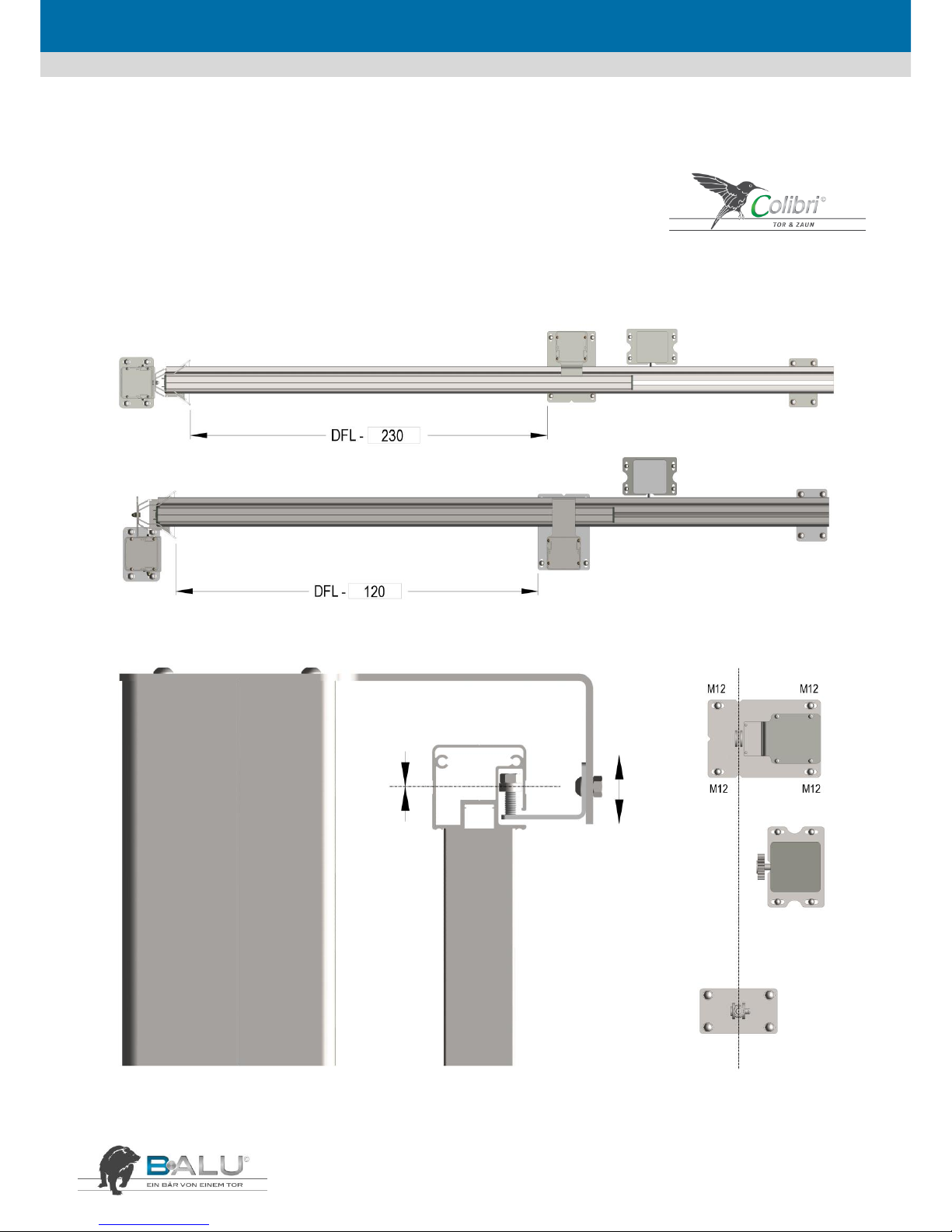
Spezialanleitung – Colibri
Schiebetormotor Extern 60
Deimos BT D Prox MA

DEUTSCH
27
11. Spezialanleitung BALU Drehtor
Pfosten Dübelmontage
Pfosten zum Einbetonieren
Manuelles Drehtor
CB 1,3,4
Automatiksystem
CB 2
Automatiksystem
DEUTSCH
28
Spezialanleitung Drehtormotor
Colibri + BALU
ZLJ14 für CB 1,3,4 - einflügelig
DEUTSCH
29
Spezialanleitung Drehtormotor
Colibri + BALU
ZLJ24 für CB 1,3,4 - zweiflügelig
DEUTSCH
30
Spezialanleitung Drehtormotor
Colibri + BALU
ZA3 für CB 2

DEUTSCH
31

DEUTSCH
32
12. Spezialanleitung Schiebetormotor - INLINE 160 400V
Sheda Base ZT6

DEUTSCH
33

DEUTSCH
34
13. Konformitäts- und Leistungserklärungen
Konformitäts- und Leistungserklärung
gemäß EG-Maschinenrichtlinie 2006/42/EG, EN 1090, Bauproduktverordnung von 2013
Firma: HOLLER-TORE GmbH LEIBNITZ,
Dorfstraße 31, A- 8430 Leitring
Hiermit bescheinigen wir in alleiniger Verantwortung die Konformität des Erzeugnisses
Schiebetor H-T B·ALU Industrie
H-T B·ALU ECO
Antrieb INLINE 100, INLINE 120, INLINE 160, INLINE 250
EXTERN 60, EXTERN 180
mit den grundlegenden Anforderungen der folgenden EG-Richtlinien:
EG-Bauprodukterichtlinie 89/106/EWG,
EG-Maschinenrichtlinie 2006/42/EG,
EG-Niederspannungsrichtlinie 2006/95/EG,
EG-Richtlinie über Elektromagnetische Verträglichkeit 2004/108/EG.
Insbesondere wurden folgende harmonisierte Normen angewandt:
EN13241-1 Tore – Produktnorm, Produkte ohne Feuer und Rauchschutzeigenschaften
EN 12100 Sicherheit von Maschinen – Grundbegriffe, allgem. Gestaltungsleitsätze
EN 12445 Nutzungssicherheit kraftbetätigter Tore, Prüfverfahren
EN 12453 Nutzungssicherheit kraftbetätigter Tore, Anforderungen
EN 12978 Schutzeinrichtungen für kraftbetätigte Türen und Tore
EN 414 Sicherheit von Maschinen – Regeln für die Abfassung und Gestaltung von Sicherheitsnormen
EN ISO 13850 Sicherheit von Maschinen – NOT - AUS-Einrichtung, funktionelle Aspekte – Gestaltungsleitsätze
EN ISO 13849-1 Sicherheit von Maschinen – Sicherheitsbezogene Teile von Steuerungen
EN 1037 Sicherheit von Maschinen – Vermeidung von unerwartetem Anlauf
EN 12100 Sicherheit von Maschinen – Leitsätze zur Risikobeurteilung
EN 60204-1 Sicherheit von Maschinen – Elektrische Ausrüstung von Maschinen
Leitring, 2013-01-11
Dokumentationsbevollmächtigter
Ewald Holler
Geschäftsführer

DEUTSCH
35
14. Allgemeine Liefer- und Geschäftsbedingungen
Allgemeine Liefer- und Geschäftsbedingungen der Holler-Tore GmbH, A-8430 Leitring, Dorfstraße 31
1. Vorwort
Holler Tore nimmt Aufträge entgegen, verkauft und liefert
ausschließlich auf Grund dieser Verkaufs- und Lieferbedingung. Diese
nachstehenden Bedingungen gelten für alle Leistungen, die Holler Tore
oder ein von ihm namhaft gemachtes Subunternehmen im Rahmen
eines Auftrages durchführt. Mündlich vereinbarte Änderungen oder
Ergänzungen dieses Vertrages sind nur wirksam, wenn sie von Holler
Tore schriftlich bestätigt worden sind. Geschäftsbedingungen des
Auftraggebers werden für das gegenständliche Rechtsgeschäft und die
gesamte Geschäftsbeziehung ausdrücklich ausgeschlossen. Etwaige
Unwirksamkeit einzelner Bestimmungen hat auf die übrigen
Geschäftsbedingungen keinen Einfluss. Sämtliche in Holler Tore
Unterlagen enthaltene Ang aben über Preise, Gewichte, Maße oder
technische Daten etc. sind nur in dem Fall verbindlich, in dem
ausdrücklich auf sie Bezug genommen wird. Technische Änderungen
vorbehalten.
2. Warenlieferungen
Die Lieferung erfolgt auf Rechnung und Gefahr des Auftraggebers.
Holler Tore ist berechtigt, Teil- oder Vorlieferungen durchzuführen und
zu verrechnen. Beanstandungen hat der A uftraggeber sofort nach
Empfang der Ware beim Transportunternehmen ( Frachtscheinvermerk
) und Holler Tore schriftlich, spätestens jedoch binnen acht Tagen,
vorzubringen. Aufbewahrungsmaßnahmen und Aufbewahrungskosten,
welche aus Gründen notwendig werden, die in der Sphäre des
Auftraggebers liefen, gehen zu Lasten und auf Kosten des Auftraggebers
und gelten als Ablieferung, sobald diese Aufbewahrungsmaßnahmen
beginnen. Sachlich gerechtfertigte und angemessene Änderungen der
Leistungs- und Lieferverpflichtung von Holler Tore, insbesondere
angemessene Lieferfristüberschreitungen, gelten vom Auftraggeber als
vorweg genehmigt. Angekündigte Liefertermine gelten, als bloß
annähernd geschätzt. Höhere Gewalt oder andere unvorhergesehene
Hindernisse in der Sphäre von Holler Tore oder dessen Unterlieferanten
entheben Holler Tore von der Einhaltung der vereinbarten Lieferzeit.
Der Auftraggeber ist verpflichtet nach Verständigung durch Holler Tore
die bei Holler Tore gelagerte Ware unverzüglich abzuholen. Betriebsund Verkehrsstörung und nicht ordnungsgemäße Lieferung von
Unterlieferanten gelten auch als höhere Gewalt und befreien Holler
Tore für die Dauer der Behinderung oder nach Wahl H oller Tore auch
endgültig von der Verpflichtung zur Lieferung, ohne dass dem
Auftraggeber Ansprüche auf Grund des Rücktrittes durch Hol ler Tore
entstehen. Holler Tore steht es frei, die Art der Versendung der Ware
und das Transportmittel auszuwählen. Erfüllungsort für Lieferung und
Zahlung ist der Geschäftssitz von Holler Tore.
3. Angebotsstellung und Preisauskünfte
Die Angebote von Holler Tore, ob schriftlich, mündlich oder telefonisch
sind, wenn dies nicht ausdrücklich anders vermerkt ist, gültig ab Werk.
Ein Kaufvertrag kommt nur zustande, wenn Holler Tore innerhalb der
Annahmefrist entweder eine schriftliche Auftragsbestätigung sendet,
oder die bestellten Vertragsgegenstände liefert. Die Annahmefrist
beträgt generell 4 Wochen. Alle Angebote sind freibleibend. Es bes teht
für Holler Tore keine Pflicht zur Auftragsannahme.
4. Fertigungstoleranzen und Freiräume
Mengenangaben in Angeboten erfolgen ohne Gewähr. Abweichungen
von Prospektangaben, Abbildungen und Mustern in Farbe, Maßen,
Gewichten und Qualitäten, bleiben vorbehalten. So ferne
Abweichungen nicht ohnedies dem Kunden zumutbar sind, besonders
weil sie geringfügig und sachlich gerechtfertigt sind, kann Holler Tore
von der bestellten Leistung produktionsbedingt abweichen. Technische
Änderungen bleiben ausdrücklich vorbehalten.
5. Kostenvoranschläge
Der Kostenvoranschlag wird nach bestem Fachwissen erstellt, es kann
jedoch keine Gewähr für die Richtigkeit übernommen werden. Die
Kosten für die Erstattung eines Kostenvoranschlages, so fern solche
auflaufen, werden dem Auftraggeber verrechnet. Jegliche
Kostenvoranschläge können nur schriftlich erteilt werden. So fern aus
diesen nichts anderes hervorgeht ist Holler Tore an diese vier Wochen
lang gebunden.
6. Forderungseintreibungs-, Mahn- und Inkassospesen
Für den Fall des Zahlungsverzuges ist der Auftraggeber verpflichtet,
Holler Tore sämtliche von ihm aufgewendeten vorprozessualen Kosten,
wie etwa Anwaltshonorare und Kosten von Inkassobüros, zu erstatten,
sofern diese Kosten zur zweckentsprechenden Rechtsverfolgung
notwendig waren. Es verpflichtet sich der Auftraggeber pro erfolgter
Mahnung, einen Betrag von EUR 15,-- zuzüglich zu den anfallenden
Zinsen in der Höhe von 14 % p.a. und sämtliche anfallende
Sonderkosten zu bezahlen.
7. Garantien, Gewährleistungen und Haftungen
Für alle Produkte die im Sinne des HR an Unternehmen geliefert werden
ist die Gewährleistung auf 1 Jahr ab Warenanlieferung / Übernahme
beschränkt. Tritt bei der gelieferten Ware ei n Mangel auf, kann der
Auftraggeber vorerst nur die Verbesserung oder den Austausch der
Ware verlangen. Holler Tore verpflichtet si ch die Verbesserung und den
Austausch nach Übergabe der Ware durch den Auftraggeber in
angemessener Frist durchzuführen, wobei als angemessene Frist die
jeweilige unverbindliche Lieferfrist als vereinbart gilt. Als
Gewährleistungabwicklung ist eine Send & Retourn Durchführung
vereinbart., Erfüllungsort ist der ursprüngliche Lieferort. Es wird
vereinbart, dass der Auftraggeber sei n Recht auf Gewährleistung bei
beweglichen und unbeweglichen Sachen im Sinne des § 933 ABGB
binnen sechs Monaten gerichtlich geltend machen muss. Darüber
hinaus gewährt Holler Tore für Profilteile (keine Alu-Gussteile) eine
Beschichtungsgarantie von 15 Jahre (Holler Tore
Beschichtungsgarantie), dies jedoch ausschließlich unter folgenden
Voraussetzungen: 1. Die Reinigung und Pflege muss ausschließlich durch
Holler Tore-Pflegeprodukte erfolgen. Eine Pflege hat nachweislich
dergestalt zu erfol gen als zumindest zweimal jährlich der
Garantiegegenstand mit Holler Tore-Oberflächenpflege durch
geschultes und autorisiertes Holler Tore Personal gereinigt, sowie
anschließend mit dem Holler Tore-Imprägniermittel imprägniert wird. 2.
Es darf keine unsachgemäße Behandlung durch den Käufer oder durch
Dritte erfolgen. 3. Das Garantieprodukt darf nicht mit Salzen,
kalkhaltigem Wasser oder ähnlich beschaffenen Auftaumi tteln, Säuren
und Laugen in Berührung kommen. 4. Es darf darüber hinaus keine
Einwirkung durch höhere Gewalt erfolgen (mechanische
Beschädigungen). Die Garantie bezieht sich ausschließlich auf Ersatz des
Materialaufwandes für die Reparatur. Den Auftraggeber trifft
unbeschadet seiner Rechte die Obliegenheit, sich ausdrücklich
bedungene Eigenschaften des bestellten Vertragsgegenstandes
bestätigen zu l assen. Als gewöhnlich vorausgesetzte Eigenschaften
gelten die von den Herstellern angegebenen Produkteigenschaften,
sowie jene Eigenschaften, die bei sachgerechter und zweckgewidmeter
Anwendung an das Produkt gestellt werden können, sowie die
einschlägigen EN und Ö-Normen. Hinsichtlich der
Oberflächenbeschichtung gilt ausdrücklich die Geltung der Ö-Norm EN
12206-1 als vereinbart. Einstellungsarbeiten an Türen bzw. Toren bei
Ausführung eines nicht durchgehenden Fundamentes stell en keinen
Mangel dar. Den Auftraggeber trifft unbeschadet sei ner Rechte die
Obliegenheit, bei der Auslieferung der Ware durch Holler Tore deren
Übereinstimmung mit der Bestellung sofort optisch, als auch nach
Maßgabe angegebener Produktbezeichnungen und Chargenziffern zu
kontrollieren.
Es werden Schadenersatzansprüche des Auftraggebers grundsätzlich
ausgeschlossen.. Die Haftung für grob fahrlässiges oder vorsätzliches
Verhalten ist außer gegenüber Konsumenten mit der Höhe des
zweifachen Nettobetrages der Ware beschränkt. Bei Nichteinhalten
unserer Bedingungen für Montage, Inbetriebnahme und Benutzung ist
jeder Schadenersatz ausgeschlossen. Von jeglicher Schädigung hat der
Kunde Holler Tore unverzüglich zu informieren. Technische Auskünfte
von Holler Tore sind ohne Gewähr und bedürfen, soweit sie über die
Angaben des Herstellers hi nausgehen, der schriftlichen Bestätigung
durch Holler Tore. Außer für Schäden an der Person werden
Schadenersatzforderungen des A uftraggebers wegen verspäteter
Lieferung oder wegen Vertragsrücktritt ausgeschlossen. . ..
8. Zahlungsbedingungen
Die Rechnungslegung erfolgt, soweit möglich, umgehend nach
Lieferung. Zahlungen sind nach Rechnungslegung ohne jeden Abzug und
spesenfrei fällig. Für Teilrechnungen gelten die für den Gesamtauftrag
festgelegten Zahlungsbedingungen analog. Bei Aufträgen, die mehrere
Einheiten umfassen, ist Holler Tore berechtigt, nach Lieferung jeder
einzelnen Einheit oder Leistung Rechnung zu legen. Der Auftraggeber ist
nicht berechtigt, Zahlungen wegen nicht vollständiger Lieferungen,
Garantie- oder Gewährleistungsansprüchen oder Bemängelungen
zurückzuhalten. Bei Holler Tore einlangende Zahlungen des
Auftraggebers tilgen zuerst Zinseszinsen, die Zinsen und Nebenspesen,
die v orprozessualen Kosten, wie Kosten eines bei gezogenen Anwaltes
und Inkassobüros, dann das aushaftende Kapital, beginnend bei der
ältesten Schuld. Bei Zahlungsverzug werden von BALU Verzugszinsen in
Höhe von 14 % p.a. bei vierteljährlicher Verrechnung vereinbart. Bei
Nichteinhaltung zweier Raten bei Teilzahlungen ist Holler Tore
berechtigt, Terminverlust in Kraft treten zu lassen und übergebene
Akzepte entsprechend fällig zu stellen. Ist der Auftraggeber so derartig
in Zahlungsverzug, dass auch nur eine offene Rechnung durch Holler
Tore eingeklagt werden muss, wird vereinbart, dass hinsichtlich
sämtlicher offenen Rechnungen von Holler Tore g egenüber dem
Auftraggeber Fälligkeit eintritt und etwaige Skonti oder Rabatte bzw.
Nachlässe hinfällig sind. Bei Nichteinhaltung der Zahlungsbedingungen
von Holler Tore sowie bei begründeter Sorge der Zahlungsfähigkeit des
Käufers (also bereits bei einer Zahlungsstockung) ist Holler Tore
berechtigt, noch ausstehende Lieferungen und Leistungen
zurückzuhalten, Vorauszahlungen bzw. Sicherstellungen zu fordern oder
ohne Setzung einer Nachfrist vom Vertrag zurückzutreten.
9. Eigentumsvorbehalt
Die gelieferte Ware bleibt bis zur Bezahlung aller Forderungen von
Holler Tore aus der Lieferung (einschließlich Zinsen und Kosten)
uneingeschränktes Eigentum von Holler Tore. Verpfändungen und
Sicherungsübereignungen durch den Auftraggeber vor restloser
Bezahlung gelten als ausgeschlossen. Kommt der Auftraggeber seinen
Verpflichtungen aus dem abgeschlossenen Vertrag nicht
ordnungsgemäß nach, so ist Holler Tore jederzeit berechtigt, sein
Eigentum auf Kosten des Auftraggebers zurückzuholen, zu dessen
Herausgabe sich der Auftraggeber ausdrücklich verpflichtet. Sollte die
noch im Eigentum v on Holler Tore gelieferte Ware gepfändet oder
beschlagnahmt werden, so verpflichtet si ch der Auftraggeber Holler
Tore innerhalb von drei Tagen zu verständigen und H oller Tore
sämtliche zur Durchsetzung des Eigentumsrechts erforderlichen
Informationen zu erteilen. Falls Dritte auf die noch im
Eigentumsvorbehalt von Holler Tore stehende Ware zugreifen bzw.
Ansprüche geltend machen, verpflichtet sich der Auftraggeber darauf
hinzuweisen, dass diese Ware im Eigentum von Holler Tore steht. Die
Geltendmachung des Eig entumsvorbehaltes durch Holler Tore stellt
keinen Vertragsrücktritt durch Holler Tore dar. Für ein bestimmtes
Bauvorhaben ausg eführte Lieferungen, auch wenn sie abschnittsweise
bestellt, ausgeliefert und verrechnet werden, gelten als einheitlicher
Auftrag. Bei Zahlungsverzug, sowie bei begründeter Sorge um die
Zahlungsfähigkeit des Käufers (es genügt bereits Zahlungsstockung) ist
Holler Tore berechtigt, bi s dato geltende Vereinbarungen mit sofortiger
Wirkung einseitig abzuändern ( Rabatte , Verkaufsgebiete usw. ), die
unter Eigentumsvorbehalt stehende Ware einzuziehen, ohne damit vom
Vertrag zurückzutreten. Bei allen Warenrücknahmen hat der
Auftraggeber die Holler Tore entstehenden diesbezüglichen Kosten für
Transport und Manipulation zu ersetzen.
10. Produkthaftung
Regressforderungen im Sinne des § 12 Produkthaftungsgesetzes sind
ausgeschlossen, es sei denn, der Regressberechtigte weist nach, dass
der Fehler in der Sphäre von Holler Tore verursacht und zumi ndest grob
fahrlässig verschuldet wurde. Sofern der Auftraggeber kein Verbraucher
nach dem KSchG ist, wird die Haftung für Sachschäden aus ei nem
Produktfehler nach Maßgabe des § 8 Produkthaftungsgesetzes
ausgeschlossen und zwar auch für alle an Herstellung, Import und
Vertrieb beteiligten Unternehmen. Für diesen Fall verpflichtet sich der
Auftraggeber diesen Haftungsausschluss auf seine Abnehmer
überzubinden. Bei Verkauf importierter Ware verpflichtet sich Holler
Tore über schriftliches Verlangen dem Auftraggeber den Vormann
binnen 14 Tagen bekannt zu geben.
11. Anwendbares Recht und Gerichtsstand
Für eventuelle Streitigkeiten wird die örtliche Zuständigkeit des sachlich
zuständigen Gerichtes in 8430 Leibnitz ausschließlich vereinbart. Es gilt
österreichisches materielles Recht. Die Anwendbarkeit des UNKaufrechtes als auch die Verweisungsnormen des IPRG werden
ausgeschlossen.
12. Abtretung von Forderungen
Bei Lieferung unter Eigentumsvorbehalt tritt der Auftraggeber Holler
Tore schon jetzt seine Forderungen gegenüber Dritten, soweit diese
durch Veräußerung oder Verarbeitung unserer Waren entstehen, bis zur
endgültigen Bezahlung unserer Forderungen zahlungshalber ab. Diese
Zession ist in den Geschäftsbüchern, Lieferscheinen, Fakturen, etc. dem
Abnehmer ersichtlich zu machen. Ist der Auftraggeber mit seinen
Zahlungen Holler Tore gegenüber im Verzug, so sind bei ihm eingehende
Verkaufserlöse anzusondern und hat bzw. hält der Auftraggeber diese
nur im Namen von Holler Tore inne. Allfällige Ansprüche gegen einen
Versicherer sind in den Grenzen des jeweils geltenden
Versicherungsgesetzes bereits jetzt an Holler Tore abzutreten. Der
Auftraggeber ist nicht berechtigt etwaige Gegenforderungen gegen
Holler Tore gegen Ansprüche von Holler Tore aufzurechnen. Es sei denn,
diese Gegenansprüche sind von Holler Tore schriftlich anerkannt
worden.
13. Datenschutzerklärung – Adressänderung
Der Auftraggeber erteilt seine Zustimmung, dass die im Kaufvertrag mit
enthaltenen personenbezogenen Daten in Erfüllung des Vertrages von
Holler Tore automationsunterstützt gespeichert und verarbeitet werden
können. Der Auftraggeber ist verpflichtet, H oller Tore Ä nderungen
seiner Wohn- bzw. Geschäftsadresse bekannt zu geben, solange das
vertragsgegenständliche Rechtsgeschäft nicht beiderseitig erfüllt ist.
Wird die Mitteilung unterlassen, so gelten Erklärungen auch dann als
zugegangen, falls sie an die zuletzt bekannt gegebene Adresse gesendet
werden.
14. Abschlussbestimmungen
Für den Verkauf an Verbraucher im Sinne des
Konsumentenschutzgesetzes gelten die vorstehenden Bestimmungen
nur insoweit, als das Konsumentenschutzgesetz nicht zwingend andere
Bestimmungen vorsieht. Höhere Gewalt oder andere unvorhergesehene
Hindernisse in der Sphäre von Holler Tore entbinden diesen von der
Einhaltung der vereinbarten Verpflichtungen für die Dauer der höheren
Gewalt. Der Auftraggeber verzichtet ausdrücklich die abgeschlossenen
Verkaufs- und Zahlungsbedingungen, aus wel chem Grund auch immer,
auch wegen Verkürzung über die Hälfte des wahren Wertes sowie
gegen Irrtums anzufechten.

DEUTSCH
36
15. Prüfbuch für kraftbetätigte Tore
_____________________________________
Bezeichnung
Torart: ________________________________
Firma: ________________________________
Standort: ______________________________
1. Grundlagen für die Prüfung von kraftbetätigten Toren
Die sicherheitstechnischen Anforderungen und Prüfverfahren für Bau und
Ausrüstung von kraftbetätigten Toren sind in europäischen Normen festgelegt, die
die allgemeinen Anforderungen der europäischen Maschinenrichtlinien
konkretisieren.
Diese sind insbesondere:
• DIN EN 12604 Tore: mechanische Aspekte, Anforderungen
• DIN EN 12605 Tore: mechanische Aspekte, Prüfverfahren
• DIN EN 12453 Tore: Nutzungssicherheit kraftbetätigter Tore, Anforderungen
• DIN EN 12445 Tore: Nutzungssicherheit kraftbetätigter Tore, Prüfverfahren
• DIN EN 12635 Tore: Einbau und Nutzung
Nach BGR 232 Abschnitt 6 müssen kraftbetätigte Tore vor der ersten Inbetriebnahme
und nach Bedarf, jedoch jährlich mindestens einmal, von einem Sachkundigen
geprüft werden. Diese Prüfung ist nicht mit einer Wartung gleichzusetzen.
Sachkundiger ist, wer aufgrund seiner fachlichen Ausbildung und Erfahrung
ausreichende Kenntnisse auf dem Gebiet der kraftbetätigten Tore hat und mit den
einschlägigen staatlichen Arbeitsschutzvorschriften, Unfallverhütungsvorschriften
und allgemein anerkannten Regeln der Technik (z.B. BG-Regeln, DIN Normen, VDEBestimmungen) soweit vertraut ist, dass er den arbeitssicheren Zustand von Toren
beurteilen kann. Zu diesen Personen zählen z.B. Sachverständige, Fachkräfte der
Hersteller-, Liefer- oder Montagefirmen oder einschlägig erfahrene Fachkräfte des
Betreibers. Sachkundige haben ihre Begutachtung objektiv vom Standpunkt der
Arbeitssicherheit aus abzugeben, unbeeinflusst von Anderen, z.B. wirtschaftlichen
Umständen. Das Ergebnis der Prüfung ist schriftlich festzuhalten. Der schriftliche
Nachweis sollte am Betriebsort der kraftbetätigten Tore zur Einsichtnahme
bereitgehalten werden. Länderspezifische Anforderungen an Installation und Prüfung
sind zusätzlich zu beachten!

DEUTSCH
37
2. Daten der Anlage
1. Anschrift des Betreibers: ______________________________________________
______________________________________________
Betriebsort der Anlage: _______________________________________________
2. Bezeichnung: _________________________________________ Typ: _______
Seriennummer: ________ Baujahr: ________ Inbetriebnahme am: __________
3. Flügel
Hersteller oder Lieferant: ______________________________________________
Abmessungen: __________________________ Werkstoff: ___________________
Flügelfüllung: ________________________________________________________
4. Antrieb
Hersteller oder Lieferant: ______________________________________________
Typ: ________________________________ Leistung: ______________________
Betriebsspannung: ____________________ Steuerspannung: ________________
5. Steuerung
Art der Steuerung, z.B. Taster, Totmannsteuerung, Fernsteuerung
(Lichtschranke, Funkhandsender, Induktionsschleife): _______________________
____________________________________________________________________
6. Sicherung der Hauptschließkante
Schaltleiste, Schließkantensicherung, Kraftbegrenzung
Berührungslos wirkende Schutzeinrichtung, z.B. Lichtgitter, Lichtschranke, Radar
Sonstiges: ___________________________________________________________
7. Zusätzliche Sicherung gegen Sachbeschädigung; z.B. Lichtschranke in der
Durchfahrtsöffnung
8. Sonstige Angaben: ____________________________________________________
____________________________________________________
3. Prüfliste für kraftbetätigte Schiebetore
Bezeichnung: ________________________________________
Typ: ________________________________________________ Serien Nr.:________________________
Baujahr / Inbetriebnahme: ______________________________ Lieferant: ________________________
Farbe: ______________________________________________ Motortyp: ________________________
OK
empfohlen n. vorhd. OK
empfohlen n. vorhd.
0.0
Grundprüfung
3.0
Steuerung
0.1
Optischer Eindruck
3.1
Steuerorg. Drucktaster,
Schlüsselsch.
0.2
Probeöffnung
3.2
Endschalter
0.3
Allgemeine Funktion
3.3
Not-Aus-Taster
0.4
Typenschild
3.4
Einrichtung für Fernsteuerung
0.4
CE-Kennzeichnung
3.5
Induktionsschleifen
1.0
Flügel, Mechanik
4.0
Sicherheitseinrichtung
1.1
Flügel und Flügelfüllung
4.1
Elektr. Schaltleisten
1.2
Führungen, Laufschienen,
Balken, Anschläge
4.2
Kraftbegrenzung
1.3
Laufrollen, Rollppapp.,
Abdeckungen
4.3
Totmannsteuerung
1.4
Aufhängung des Flügels
4.4
Berührungslos wirkende
Schutzeinrichtungen
4.5
Sicherheitsabstände zwischen
Flügel und festen Teilen der
Umgebung
5.0
Prüfungsbefund
2.0
Antriebe
2.1
Befestigung des Antriebes
2.2
Dichtigkeit des
Getriebegehäuses
2.3
Bremswirkung,
Nachlaufweg
2.4
Rutschkupplung
2.5
Zustände der elektrischen
Leitungen und Anschlüssen
2.6
Kraftübertragung (Ritzel)
2.7
Einrichten zur
Handbetätigung
2.8
Entkupplung
Prüfung durchgeführt am: ___________________________________
Termin nächste Prüfung: ___________________________________
____________________________ ________________________
Unterschrift Prüfer Unterschrift Auftraggeber

DEUTSCH
38
4. Zusatzerklärung Montage
(Ergänzung zu der Konformitätserklärung des Herstellers / Inverkehrsbringers)
Die Firma ______________________________________________________
Name ______________________________________________________
Adresse ______________________________________________________
______________________________________________________
______________________________________________________
erklärt hiermit die Einhaltung aller Montagevorgaben gemäß der Montageanleitung
bzw. der Betriebsanleitung des Torherstellers, sowie die fachgerechte Montage unter
Verwendung des dem Montageort bzw. dem Montageuntergrund entsprechenden
Montagematerials.
Der Unterzeichner dieser Erklärung ist __________________ (*) des Unternehmens.
(*) z.B. Inhaber, Gesellschafter, Geschäftsführer.
_________________ _________________ ______________________
Ort Datum Firmenstempel / Unterschrift
5. Übergabe und Benutzerhinweise
(Daten der Anlage entsprechend Erklärung Punkt 2,3 und 4)
Anwesende Personen welche in die Toranlage eingewiesen wurden:
________________________________________ ________________________________________
Name Unterschrift
________________________________________ ________________________________________
Name Unterschrift
________________________________________ ________________________________________
Name Unterschrift
________________________________________ ________________________________________
Name Unterschrift
Impulsgeber vorgeführt: Ja Nein
Handsender übergeben: Ja Nein
Schlüssel übergeben: Ja Nein
Sicherheitseinrichtungen vorgeführt: Ja Nein
Notentriegelung vorgeführt und darauf hingewiesen, dass diese nur bei stehender Anlage ent- und
verriegelt werden darf: Ja Nein
Displayanzeigen erklärt: Ja Nein
Auf Wartungsintervalle hingewiesen: Ja Nein
___________________________________________________________
Ort / Datum der Anlagenübergabe
technische Unterlagen übergeben: Ja Nein Ort / Datum der Anlagenübergabe
___________________________________ ___________________________________
Unterschrift Prüfer Unterschrift Auftraggeber

DEUTSCH
39
Notizen

ENGLISH
Instructions for installation and use

ENGLISH
1
Manual for the fitter and end user
Dear Customer,
We are pleased to learn that you have decided to opt for our gate. This Installation and operation manual contains all the information
necessary to understand the principle of operation of the product. We would like to ask you to read the information in this man-ual
carefully before commencing work on this product.
It should be installed only by authorized specialists. The table of contents is meant to help you in locating information that you need in this
manual.
Rules and regulations specific to a given country need to be observed and followed in addition to others given here!
Disclaimer
This gate should be used only for closing passages dy-namically.
Holler-Tore does not assume any liability whatsoever for any damage that is caused by improper, incorrect and unauthorized use. Please
read this manual completely.
Holler-Tore points out that the gates manufactured by them bear the CE marking.
In addition, we provide all technical documentation and an installation and operation manual.
These gates conform to the regulations of the EN 13241-1 standard. Certain requirements are also applicable to the installation of the gate,
and the installation manual must be observed and followed at all times. The installation should be carried out by a qualified and
authorized installer BALU taking all legal rules and regulations into consideration. Safety must be ensured at all times so that the user and
third persons can operate the sliding gate without any hazards. The fitter is responsible for proper and trouble-free installation. In case of
queries or clarifications regarding the installation, the fitter may contact Holler Tore for more information.
Index
1. Precautionary measures and warning instructions ............................................................................................................................................................ 2
2. Technical Specifications ................................................................................................................................................................................................... 3
3. Assembly, installation and commissioning ........................................................................................................................................................................ 6
4. Description of the operation and use ............................................................................................................................................................................. 12
5. Maintenance and servicing schedule .............................................................................................................................................................................. 14
6. Environment, disassembly, storage and transport ........................................................................................................................................................... 15
7. Programming instructions ............................................................................................................................................................................................. 15
8. Installation instructions for the connection of the 2-piece supply for gates above 10.5 m in width .................................................................................... 22
9. Special Instructions BALU ECO ....................................................................................................................................................................................... 23
10. Special Instructions Colibri ............................................................................................................................................................................................. 24
11. Swing Gate ................................................................................................................................................................................................................... 26
12. Inline 160..................................................................................................................................................................................................................... 31
13. Declaration of Conformity and Perfomance .................................................................................................................................................................... 33
14. General Terms and Conditions for Delivery and Sales ...................................................................................................................................................... 34
15. Test log for power-operated gates ................................................................................................................................................................................. 35

ENGLISH
2
1. Precautionary measures and warning instructions
IMPORTANT INSTRUCCIONS:
Prior to commencing the installation work, hand over a copy of the installation and operation manual to the user.
The user instruction on the use and check the gate and post to ensure that they are working properly before starting the
installation.
Secure the work area again, no unauthorized entry prior to and during the installation. Take public safety into
consideration appropriately depending on the circumstances. Particularly when working near schools, special attention
must be paid to the safety of children.
Always use approved lifting tools to transport heavy loads. Always work with more than one person when doing any
hoisting or lifting work even if you are using lifting aids. The maximum weight of a load to be transported by one single
person should not exceed 25 kg.
Always wear the personal safety gear required e.g. safety gloves, safety shoes (at least class S3), safety goggles, ear
muffs, dust respirator and overalls.
All the installation work must be carried out by qualified and authorized BALU fitter. The fitter is obliged to provide
qualified specialists with relevant experience for deployment.
Waste materials must be isolated. Enquire about regional options for safe and proper disposal.

ENGLISH
3
2. Technical Specifications
2.1. General Product Specifications
BALU Manual
Post dimensions: 150 x 150 mm
BALU Inline 100
Maximum gate width: 10m
Maximum gate weight: 700 kg
ED: 70 %
Noise level: < 80 dB (A)
Mains connection: 230 V
Motor operating voltage: 24 V
Post dimensions: 220 x 170 mm
BALU Inline 120
Maximum gate width: 12 m
Maximum gate weight: 1.000 kg
ED: 70 %
Noise level: < 80 dB (A)
Mains connection: 230 V
Motor operating voltage: 24 V
Post dimensions: 220 x 170 mm
BALU Extern 180
Maximum gate width: 18 m
Maximum gate weight: 2.000 kg
ED: 70 %
Noise level: < 80 dB (A)
Mains connection: 230 V
Motor operating voltage: 24 V
Post dimensions: 150 x 150 mm
BALU Inline 160
Maximum gate width: 16 m
Maximum gate weight: 1.300 kg
ED 80 %
Noise level: < 80 dB (A)
Mains connection: 400 V
Motor operating voltage: 400 V
Post dimensions: 220 x 170 mm
BALU Inline 250
Maximum gate width: 25 m
Maximum gate weight: 3.000 kg
ED 100 %
Noise level: < 80 dB (A)
Mains connection: 230 V
Motor operating voltage: 230 V
Post dimensions: 220 x 170 mm

ENGLISH
4
2.2. Tools required
Spade
Trowel
Drill bit 18 mm
Drill brush
Air pump
Resin capsule, M 16
Spirit level
Spanners SW 17 and 24
Threaded rods, nurts and
washers M16
Allen key, 6 and 8

ENGLISH
5
2.3. The most important components
2.3.1. Manual
2.3.2. Inline
2.3.3. Extern

ENGLISH
6
80 cm
3. Assembly, installation and commissioning
3.1. General
Cordon off the work area against unauthorised entry prior to and during the
installation. The safety of third persons must remain ensured.
Always wear the personal safety gear required, e.g. safety gloves, safety boots (at
least class S3), ear muffs, dust respirator and overalls.
ATTENTION! All the installation work must be carried out by qualified and skilled
workmen
3.2. Prepare the ground
STEP 1
Take care to ensure
that the entire work
area for the gate is
free from
obstructions.
The placement of
existing brickwork
can be obtained from
foundation plan.
STEP 2
1. Keep the cable route
and ducts, and accessories
if any, ready.
2. Determine the zero
position of the gate and
prepare the cladding for
the foundation.
3. Use special elbow
bends for pulling in the empty pipework. The horizontal part of the
elbow bend and empty pipework must lie at least 80 cm below the
surface of the ground.
STEP 3
Fill up the cladding
with concrete. Allow
the concrete to rest
until it has cured
completely and in
accordance with the
specifications for the
concrete.
STEP 4
Now mark the boreholes
for the installation of the
post on the foundation.
Use an 18 mm drill bit for
the boreholes.
Attention: Do not make
the boreholes for the
entry post/catcher and
the rear roller rail yet
STEP 5
1. Clean the
boreholes
2. Remove residues of
dust and dirt from the
boreholes using an air
pump
3. Insert resin
capsules
STEP 6
Now insert the threaded
rods with rotary
movement into the
boreholes. The ends of
the threaded rods must
project at least 60 mm
over the foundation.
Allow the resin anchor to
cure in accordance with
the specification (45 minutes).

ENGLISH
7
3.3. Put the sliding gate in place
Always use approved lifting tools to transport heavy loads. Always
work with more than one person when doing any hoisting or lifting
work even if you are using lifting aids. The maximum weight of a
load to be transported by one single person should not exceed 25
kg.
ATTENTION! Use hoisting gear of adequate load-bearing capacity.
The safe loading capacity is always specified on the hoisting gear.
Lifting the gate improperly may cause deformation of the gate.
(Secure the drive post!)
ATTENTION! Pay attention to ensure proper load distribution when
lifting gates! The slinging belts must have adequate load-bearing
capacity and should not be frayed. Make sure that the gate is
protected adequately! Do not use any chains!
STEP 1
1. Lower the pillars
over the ends of the
threaded rods.
2. Put washers and
nuts in place and
tighten them by
hand.
STEP 2
1. Slide the end stops,
with the help of which
the gate is secured during
transport, outwards.
Never remove the end
stops!
2. Unlock the motor
according to the motor
manual in electrically operated gates.
3. Tighten the end stops exactly in the proper position so that the
gate is aligned when it is opened or closed.
STEP 3
Bring the gate to
the closed position.
Make sure that the
passage is free from
any obstacles
Crushing hazard!
STEP 4
Adjust the level of the
post and the gate with the
help of nuts on the
threaded rods relative to
the base plate by using a
spirit level in such a
manner that they are
plumb-vertical or
horizontal.
STEP 5
Tighten all the nuts.

ENGLISH
8
3.4. Placing the entry pillar
STEP 1
Ensure that the gate is in
the closed position and
determine the position of
the entry post.
STEP 2
Mark the boreholes for the
foundation. Use the base
plate as a stencil for this
purpose. Open the gate
slightly. Remove the entry
pillar and make the boreholes
using an 18 mm drill bit.
STEP 3
1. Clean the
boreholes with a
brush. Take care to
ensure that all
residues of dust and
dirt have been
removed.
2. Clean the
boreholes. Take care to ensure that all residues of dust and dirt
have been removed.
3. Insert resin capsules
STEP 4
Insert the threaded rods
with rotary movement
into the bore-hole. The
ends of the threaded rods
must project at least 60
mm over the foundation.
Allow the resin anchor to
cure in accordance with
the specification.
STEP 5
1. Lower the entry/catcher post
over the threaded bars.
2. Put washers and nuts in place
and tighten them by hand.
STEP 6
1. Close the gate such
that the roller rail lies
flush against the lower
edge of the bottom bar
(depends on the type of
gate).
2. Adjust the entry
height such that the
clearance between the
gate and the ramp is at least 5 mm. Improper adjustment en-hances
the risk of a fault caused by a very large force required for the gate
entry movement.
STEP 7
Adjust the level of the
entry portal with the
spirit level and check
that the pillar and gate
are in parallel.
STEP 8
Tighten all the nuts.

ENGLISH
9
3.5. Place the rear roller rail in position
STEP 1
Mark boreholes on the foundation (position in accordance with the foundation plan). Use the
base plate as a stencil. Remove the rear roller rail and make the boreholes using an 18 mm drill
bit.
1. Clean the boreholes with a brush. Take care to ensure that all residues of dust and dirt have
been removed.
2. Insert resin capsules.
STEP 2
Insert the threaded rods and allow the resin anchor to cure in accordance with the specification.
Put washers and nuts in place on the rear roller rail and tighten them by hand.
STEP 3
Adjust the rear roller rail. While opening, the rear roller rail should not touch the gate.
ATTENTION! The gate should not run under pressure on the rear roller rail! The gate may get
damaged otherwise.
Adjust the height of the rear roller rail by turning the nuts. Tighten the nuts with a spanner.
3.6. Electrical installation
3.6.1. General
ATTENTION! This installation work must be carried out by a qualified and specialized electrician in accordance with the legal rules
and regulations applicable.
CAUTION! Crushing hazard and hazard caused by electric current!

ENGLISH
10
3.6.2. Inline
STEP 1
Put the photocells in place. Connect the photocells to the motor
using a cable.
STEP 2
Check once again
whether the end stop is
in the correct position:
The gate must be able to
open and close
completely, but in such a
manner that the safety
contact strip is located
ten millimetres away from the edge of the catcher post
ATTENTION! Crushing hazard!
STEP 3
ATTENTION!
DANGER TO LIFE by
electric current!
1. Check whether
the system is
electrically
deenergized. Next,
plug in the power
supply cable in the
control column according to the regulations applicable to the
power source.
2. Bring the gate to the middle position.
3. Remove the cover in the control column from the controller
and check the fuses.
STEP 4
Put the warning sign
stickers in place.
STEP 5
Latch the motor and
drive the gate to the
closed position.
STEP 6
1. Insert the main plug
into the power supply.
2. After closing the gate,
program the system in
accordance with the
instructions furnished on
the motor.
STEP 7
1. Check whether all
parts are working
smoothly and
properly.
2. Open the control
columm via the lock
on the outside of the
pillar.
3. Plug in the
connector of the rechargeable battery into the j1 jack at the top
right side on the control board.
ATTENTION! The gate also works if the mains supply is disconnected on rechargeable battery mode – crushing hazard – for
out-of-order position, also remove the plug to the
rechargeable battery!

ENGLISH
11
3.6.3. Extern
STEP 1
Place the pinion gear
in the correct position
relative to the rack,
the gap must be
minimal
(approximately 2mm),
make sure this is
correct over the
entire length. Re-adjust if the gap is too large.
STEP 2
Put the photocells in
place. Connect the
Photocell to the motor
using a cable.
STEP 3
Check once again
whether the end
stop is in the correct
position: The gate
must be able to open
and close
completely, but in
such a manner that
the safety contact
strip is located ten millimetres away from the catcher post.
ATTENTION! Crushing hazard!
STEP 4
ATTENTION! DANGER TO
LIFE by electric current!
1. Check whether the
system is electrically
de-energized. Next,
plug in the power
supply cable in the
control column
according to the
regulations applicable to the power supply.
2. Bring the gate to the middle position.
3. Remove the cover in the control column from the controller and
check the fuses.
STEP 5
Put the warning sign
stickers in place.
STEP 6
Lock the engine: 1. Rotate the knob
anticlockwise and move it back to the locked
position. 2. Close the knob cover, rotate the
key clockwise and rotate the lock protection
disk cover.
The gears are now locked and the gate is
ready for use. Once the system has been reset store the key in a
safe place.
STEP 7
1. Insert the shutdown contact into the
wall socket. The gate
must now be moved to
the closed position.
2. After closing the
gate, program the
system in accordance
with the instructions furnished on the motor.
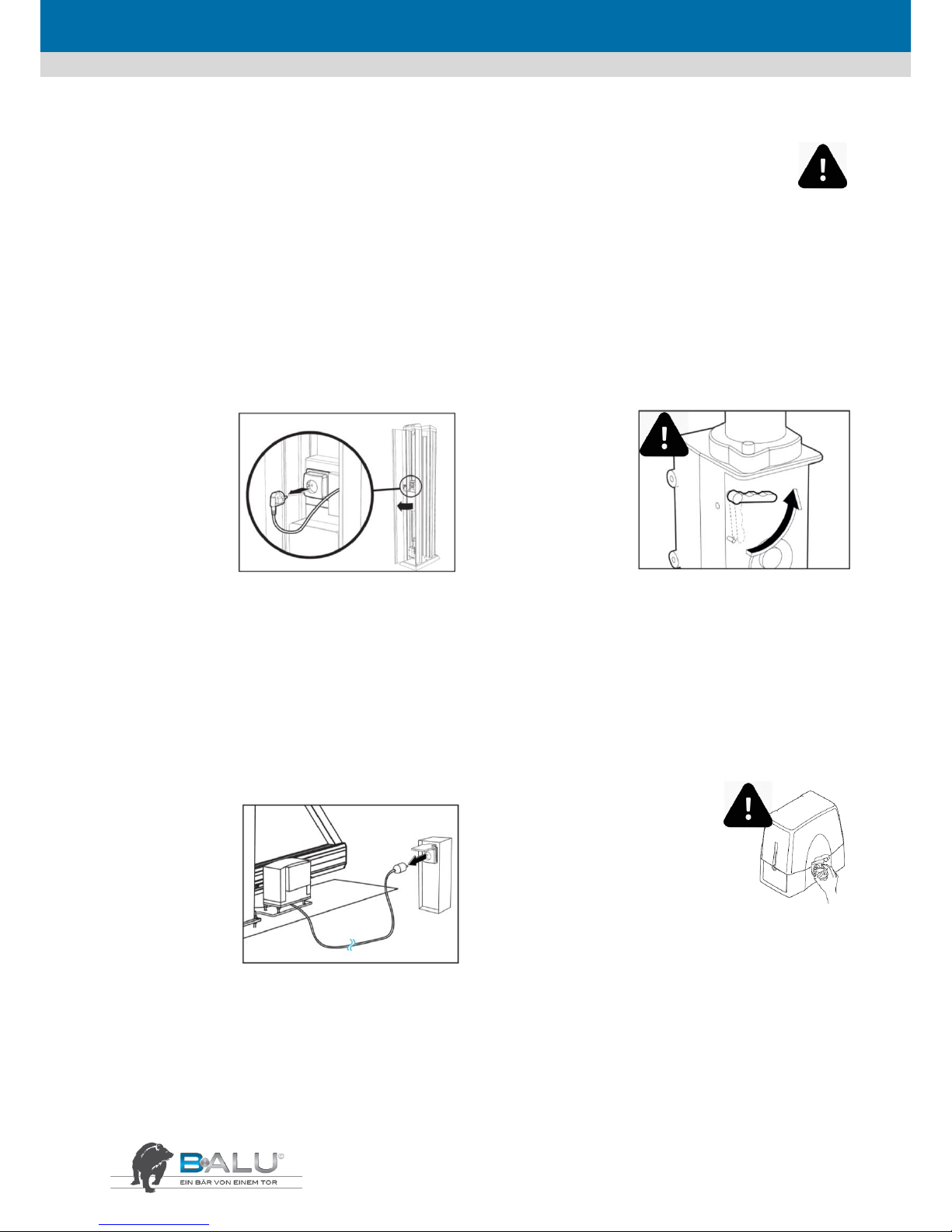
ENGLISH
12
4. Description of the operation and use
4.1. General
ATTENTION! Do not insert any objects whatsoever between the parts of the gate or do not place them on or over the gate
while it is in motion under any circumstances.
Always be at a distance from the gate while it is in motion!
It is strictly prohibited to ride along with the gate!
4.2. Shutting down the gate system
4.2.1. Inline
STEP 1
Open the pillar via
the lock located on
its outside. In order
to interrupt the gate
automatic system,
first pull out the plug
from the wall socket
and then remove the
rechargeable battery connector from the control board.
ATTENTION! DANGER TO LIFE by electric current!
STEP 2
1. Release the lock
between the gate and the
motor with the help of
the emergency locking
lever on the motor.
2. The gate can now be
moved by hand.
ATTENTION! Check that
the product is electrically de-energized!
When moving the gate by hand, take potential crushing hazards
for persons, animals and objects into account!
4.2.2. Extern
STEP 1
Open the pillar via the
lock located on its
outside. In order to
interrupt the gate
automatic system,
first pull out the plug
from the wall socket
and then remove the
rechargeable battery
con-nector from the control board.
ATTENTION! DANGER TO LIFE by electric current!
STEP 2
To release the unit
1. Rotate the lock protection disk, insert the
key, rotate it half a turn anticlockwise and lift
up the knob cover. The knob is now free and
can be released.
2. Rotate the knob clockwise until it can turn
no more. Attention: do not force the knob to turn further than its
travel limit. The gears are now released and the gate can be moved
manually.
ATTENTION! Check that the product is electrically deenergized!
When moving the gate by hand, take potential crushing hazards
for persons, animals and objects into account!

ENGLISH
13
4.3. Adjusting the product
Adjust the product in accordance with its specific usage requirements. In this way, it is possible, for example, to set the gate to fully automatic or semi-automatic mode of operation – the pause time can be adjusted and even the gate movement feature can be activated.
Information on these settings is given in the manual for the drive with controller.
4.4. Operation
Always ensure that the gate works smoothly and properly while opening and closing.
Detailed description, for example, for the programming is included in the manual supplied along with the drive with control-ler.
Attention! Whenever the gate is set to the "automatic closing" mode, special hazard analysis must be carried out prior to acti-vation.
Unlock the gate in case of power failure with the help of the locking grip on the motor and move the gate by hand.
STEP 1
Use the left button on the remote control unit to open the gate completely. If the gate is set to semiautomatic mode of operation, the left button must also be used to close the gate.
STEP 2
Use the right button of the remote control unit to use the gate movement feature. If the gate is set
to semi-automatic mode of operation, the left button must also be used to close the gate.

ENGLISH
14
5. Maintenance and servicing schedule
5.1. General
ATTENTION! This work must be carried out by a qualified and specialized technician in accordance with the legal rules and regulations
applicable.
CAUTION! Prior to carrying out servicing work on the guide post and on the entry portal, always shut down the power supply first.
Detailed description, for example, for the programming is included in the manual supplied along with the drive with controller.
5.2. Daily maintenance
Keep the gate opening free from any obstacles over the entire range of movement at all
times!
5.3. Monthly servicing
ATTENTION! Beware of the crushing hazard and the potential of an electric shock while doing maintenance!
STEP 1
Test all safety equipment and devices regularly.
This gate has been provided with various safety devices. In order to prevent accidents caused by the gate, all safety devices must be
checked regularly to ensure that they are working properly.
• Move the gate to the open position, and press the palm of your hand against one of the pressure strips. The gate must stop immediately.
Repeat this procedure with the other pressure strips.
• Clean the photocells once a month with a soft cloth. Next, close the gate and while doing so reach with your hand into the zone between
the photocell. The gate must stop immediately and start reversing.
• Check the flasher lamp on the pillar for proper working.
STEP 2
Clean the inside of the bottom bar once a month. This prevents ingress of dirt in the guide and blocking of the gate while it is in operation.
• To do this, move the gate to the closed position.
• Interrupt the power supply.
• Wipe out the bottom bar with a cloth and remove any dirt from the inside while doing so.
• Switch on the power supply again and check that the gate is working properly.
5.4. Once a year
STEP 1
Ensure that the sliding gate system is maintained once a year by specialists authorized for this purpose.
STEP 2
Replace the battery in the safety contact strip at the main closing edge once a year.

ENGLISH
15
6. Environment, disassembly, storage and transport
6.1. Environment-friendly disassembly
Have the product disposed of only by an authorized disposal company!
It should be disassembled only by specialists.
6.2. Storage and transport
If the product needs to be stored or transported, care must be taken to provide good quality packaging for this purpose. It must be stored in
a dry environment.
7. Programming instructions
7.1. Quick commissioning
The gate system is supplied with the most important default factory settings and can be customized within a few minutes: Prior to
programming, ensure that the mechanical stops for the opening and closing operations are present and have been adjusted. These have
been pushed as transport locks for the assembly.
ATTENTION: The shutdown mechanism for the force is out of operation during the learning procedure. Hence, ensure that there are no
persons or objects located in the hazard zone during the learning procedure. Make sure that no start or stop commands are issued and
that the photocell are not interrupted during operation.
Appears:
Default display with mains voltage present
Steady and continuous illumination: everything OK
Flashing: Fault
Keep the P2 „PROGR/OK“ button pressed for at least 4
seconds
Press the P2 „PROG/OK“ button 2 times. The gate opens
up to the internal Stopp, checks this and then saves it.
The gate closes automatically up to the internal stop,
checks this one again and then saves it.
INLINE 100
INLINE 120

ENGLISH
16
7.2. Terminal assignment
1 – 2
MOT
Motor connection (made at the factory)
3 – 6
ENC
Encoder connection (3 – blue/ 4 – green / 5 – grey / 6 – yellow) (done at the factory)
7
LCK
Emergency unlocking (“Motor free“ text on the display)
8
CMN
Common connection
9 – 10
LC/CH2
Connection of an externally powered ambient lamp (max. 30 V sc/dc, 1A) or pick-up 2. wireless
channel (potential-free switching contact)
11
CMN
Common termination
12
LP
Flashing lamps (24 V dc / max. 25 W flashing or 12.5 W continuously)
13
LS
Pilot lamp “Gate open“ (24 V dc / max. 3 W)
It flashes slowly while opening and flashes quickly while closing.
It lights up continuously if the gate is blocked while closing.
It goes off when the gate is closed.
14
CMN
Common connection
15
CTRL24Vdc
24 V dc for feeding the monitored light barrier transmitter
16
CMN
Common connection
17
OUT24Vdc
24 V dc for feeding the light barrier receiver
ATTENTION! Terminals 15 + 17 should be loaded with max. 10 W!
18
TA
Defined opening command
19
TC
Defined closing command
20
TAL
Partial opening (1-9 m programmable)
21
TD
Dynamic starting pule
Opening with pulse blocking until the gate opens, and pulse when the closure opens
Opening – Stopping – Closing - Stopping
22
CMN
Common connection
23
TB
Emergency stop / Connecting the safety contact strip
24
CP
Reversing safety device / Connecting the safety contact strip
25
FS
Stopping light barrier connection in the closing operation
After release, the quick movement is continued / connecting the safety contact strip
26
FI
Reversing safety device in closing operation / Connecting the safety contact strip
27
ANT
Antenna connection (Signal) (RG 58 / 50 Ω)
28
ANT
Antenna connection (Sheath)
29
CMN
Common connection for emergency operation
30
EMRG1
Operates the gate in which the controller is bypassed
If the drive is on the left side, the gate is closed, and with the drive on the right side it is opened
31
EMRG2
Operates the gate in which the controller is bypassed
If the drive is on the left side, the gate is opened, and with the drive on the right side it is closed
In this way, the controller has saved the end potition
and the operating forces that are necessary. If
„PROGRAM“ flashes on the display, the learning
operation must be restarted.
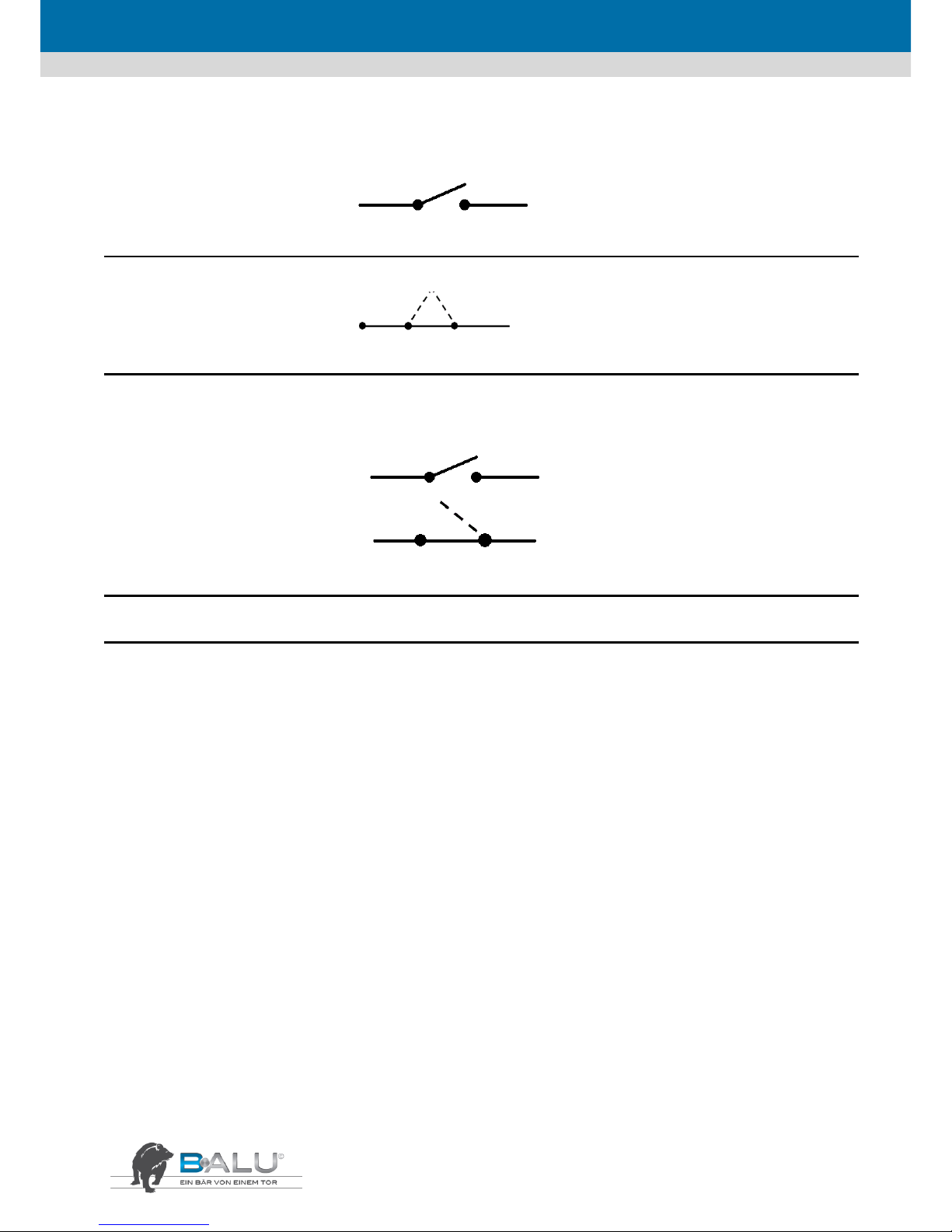
ENGLISH
17
7.3. Timer
Timer 1 channel
CMN TA
The drive opens in the time set and intermediate movement with remote operation are possible, closure with automatic closing feature.
CP (24) Model with light barrier, closure with automatic closing facility
First opening with a pulse no intermediate movement, model with light barrier, closure with automatic closing facility
Timer 2 channel
CMN TA
Serie mit Lichtschranke
CP (24)
The drive opens at the time set, intermediate movements are not possible (program channel 1 + 2 simultaneously), closing with the automatic closing feature
Programme the timer in accordance with the programming instructions!
7.4. Programming
In order that you can adapt the gate system to your specific needs, the controller provides certain features and parameters that can be
enabled or disabled or adjusted. The following scheme illustrates how you can reach the desired menu items by way of a navigational aid.
The highlighted values indicate the default factory settings.
7.4.1. Options
Press P3 once – open the menu for configuring "Options"
Press P2 once – choose the menu for configuring "Options"
Sub-menu options - change the settings with "PROG/OK"
- move with P1 or P3 up and down in the menu

ENGLISH
18
Function of the key switch
DYNAMIC BUTTON
OPEN-CLOSE.
OPEN-STOP-CLOSE
Defines the function of the terminal 21 (potential-free)
Open – Stop – Close – Stop
Opens with pulse blocking – Close - Open
Automatic closure
AUTO RECLOSURE
ON
OFF
Switches automatic closing operation on or off
Automatic closing operation after the specified time
Automatic closing operation disabled
Advanced flashing of the flashing lamp
ADV. FLASHING
ON
OFF
Enables advanced flashing of a flashing lamp connected to
terminal 12
2 x advanced flashing of the flashing lamp
The drive starts immediately without any advanced flashing
Function of the flashing lamp
FLASHING LAMP
LIT UP CONTINUOUSLY
FLASHING
Defines the function of the flashing lamp connected to terminal
12 (potential-free)
The lamp is list continuously during the movement
The lamp flashes while the gate is moving
Function of the pilot lamp
PILOT LAMP
LIT UP CONTINUOUSLY
FLASHING
Defines the function of the pilot lamp connected to terminal 13
Continuous illumination of the pilot lamp
Flashing as described under "Terminal assignment"
Function of the light barrier
REVERSAL OF
PHOTOCELL
WHEN CLOSING
ALSO WHEN STOPPING
Defines the function of the safety device connected to terminal
26
Reversal of movement when the safety device gets triggered
Pulses are blocked as long as the safety feature is enabled
Monitoring the safety
TEST FI
ON
OFF
Enables monitoring of the safety device connected to
terminal 26
Monitoring active
Monitoring not active
0
TEST FI
ON
OFF
Enables monitoring of the safety device connected to
terminal 25
Monitoring active
Monitoring not active
Direction of rotation of the motor
MOTOR INSTALLATION
LEFT
RIGHT
Defines the direction of rotation of the motor
Drive installed on the left side as seen from inside
Drive installed on the right side as seen from inside
Pulse and radio operation or dead man's operation
MANUAL
ON
OFF
Pulse operation or dead man's mode
Dead man (terminals 18/19 must remain pressed)
Pulse operation / self hold
Enable remote learning from the hand-held transmitter
REMOTE SAVING
ON
OFF
Learning of other hand-held transmitters via radio
Learning activated via radio
Deactivated, possible only via the remote menu
Wireless channel or ambient lamp
OUTPUT LC/CH2
WIRELESS CHANNEL
WATCH LIGHT
Defines the function of the terminals 9 – 10
Pick-up of the 2nd Remote channel
Ambient lamp with external supply (max. 30 V ac/dc,
1A)
Exit "Options"
OUTPUT
OK
Exit the "Options" menu
By pressing the P2 "PROG/OK" button, you return to
the main menu of the "Options" menu item

ENGLISH
19
7.4.2. Safety equipment and devices
Press P3 twice – open the menu for configuring "Safety equipment"
Press P2 once – choose the menu for configuring "Safety equipment“
Sub-menu options - change the settings with "PROG/OK"
- move with P1 or P3 up and down in the menu
TB CONTACT
NC
8K2
Defines the function of the terminal 23
Normally closed contact (jumper set)
Connection of a safety contact strip 8.2 KΩ
FI CONTACT
NC
8K2
Defines the function of the terminal 26
Normally closed contact (jumper set)
Connection of a safety contact strip 8.2 KΩ
FS CONTACT
NC
8K2
Defines the function of the terminal 25
Normally closed contact (jumper set)
Connection of a safety contact strip 8.2 KΩ
CP CONTACT
NC
8K2
Defines the function of the terminal 24
Normally closed contact (jumper set)
Connection of a safety contact strip 8.2 KΩ
OUTPUT
OK
Exit the "Safety devices" menu
By pressing the P2 "PROG/OK" button, you return to
the main menu of the "Safety devices" menu item
7.4.3. Movement
Press P3 three times – open the menu for configuring "Movement“
Press P2 once – choose the menu for configuring " Movement"
Sub-menu options - change the settings with "PROG/OK"
- move with P1 or P3 up and down in the menu
MOTOR SELECTION
i924 ESY
i924 ESB 700 kg
i924 ELB 1000 kg
Defines the motor type
No function assigned
Maximum tensile and compressive force of 700 kg
Maximum tensile and compressive force of 1,000 kg
CURRENT SENSOR
LEVEL 1…5
Adjusting the drive force
Each level increases the max. current consumption and
thus, the force of the drive by 1 ampere (Level 1 = + 2A)
RESTRICTED OPENING
METER 1…9
Defines the proximity to the posts at the time of closure
The opening width of the pedestrian opening can be set
from 1 to 9 metres here.
CLEARANCE FOR
CLOSING
0…4…9 STEPS
Defines the proximity to the posts at the time of closure
The clearance can be changed from 0 – 6 cm in 9 steps.
Default factory setting is "4" = 1 cm clearance
TIME FOR PAUSE
000…240 sec.
Defines the duration of automatic closure
If automatic closure operation is enabled in the "Options"
menu, this sets the time for which the gate is kept open
RESET PARAMETERS
OK
Load the default factory settings
Resets the controller to the default factory settings. Only
the language selected remains.
OUTPUT
OK
Exit the "Movement" menu
By pressing the P2 "PROG/OK" button, you return to the
main menu of the "Movement" menu item
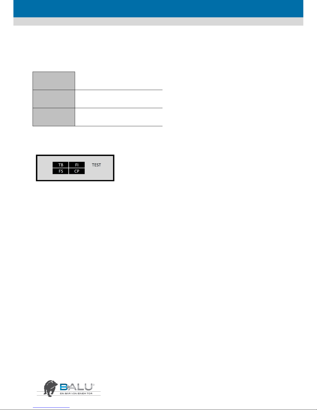
ENGLISH
20
7.4.4. Display
Press P3 four times – open the menu for configuring "Display"
Press P2 once – choose the menu for configuring "Display"
Sub-menu options - change the settings with "PROG/OK"
- move with P1 or P3 up and down in the menu
CONTRAST
OK
0…27…63
Setting the display contrast
The brightness of the display can be adjusted from 0 –
63 in the "Contrast settings" menu
BACKGROUND
LIT UP CONTINUOUSLY
60 SEC. / 30 SEC.
Background illumination of the display
The period for which the display is lit up can also be set
as 30 or 60 seconds.
OUTPUT
OK
Exit the "Display" menu
By pressing the P2 "PROG/OK" button, you return to
the main menu of the "Display" menu item
7.4.5. Test
Press P3 five times – open the menu for configuring "Remote"
Press P2 once – choose the menu for configuring " Remote "
Flashing indicates that a safety device has got triggered:
TB = Safety device connected to terminal 23 has got triggered
FI = Safety device connected to terminal 26 has got triggered
FS = Safety device connected to terminal 25 has got triggered
CP = Safety device connected to terminal 24 has got triggered
7.4.6. Wireless (Remote)
Press P3 six times – open the menu for configuring "Test"
Press P2 once – choose the menu for configuring "Test"

ENGLISH
21
Get a hand-held transmitter to learn or delete each one separately:
SAVING
OK
DELETION [n…]
Activation 1
Press the button on the handheld transmitter that needs to
be deleted
DELETION [n…]
Activation 2
Press the button to be deleted
once again to confirm
DELETION [n…]
CODE saved
The controller confirms that
the hand-held transmitter has
been deleted
DELETION
OK
DELETION [n…]
Activation 1
Press the button on the hand-held
transmitter that needs to be
deleted
DELETION [n…]
Activation 2
Press the button to be deleted
once again to confirm
DELETION [n…]
CODE saved
The controller confirms that the
hand-held transmitter has been
deleted
Delete all hand-held transmitters from the wireless receiver:
TOTAL DELETION
OK
SAVE DELETION?
OK
Use "PROG/OK" to confirm that
the entire wireless receiver
needs to be deleted
DELETION IN
PROGRESS
Specify what a wireless command should do:
CHANNEL FUNCTIONS
OK
CHANNEL A
COMMAND
TD/TAL/TA/TC
BLOCK/OUTPUT CH2
NO COMMAND
1. wireless command acts as the
dynamic start, pedestrian feature
specification for open or close, as
stop, 2nd wireless channel (terminals
9 – 10)
CHANNEL B
COMMAND
TD/TAL/TA/TC
BLOCK/OUTPUT CH2
NO COMMAND
2. wireless command acts as the
dynamic start, pedestrian feature
specification for open or close, as
stop, 2nd wireless channel (terminals
9 – 10)
CHANNEL C
COMMAND
TD/TAL/TA/TC
BLOCK/OUTPUT CH2
NO COMMAND
3. wireless command acts as the
dynamic start, pedestrian feature
specification for open or close, as
stop, 2nd wireless channel (terminals
9 – 10)
CHANNEL D
COMMAND
TD/TAL/TA/TC
BLOCK/OUTPUT CH2
NO COMMAND
4. wireless command acts as the
dynamic start, pedestrian feature
specification for open or close, as
stop, 2nd wireless channel (terminals
9 – 10)
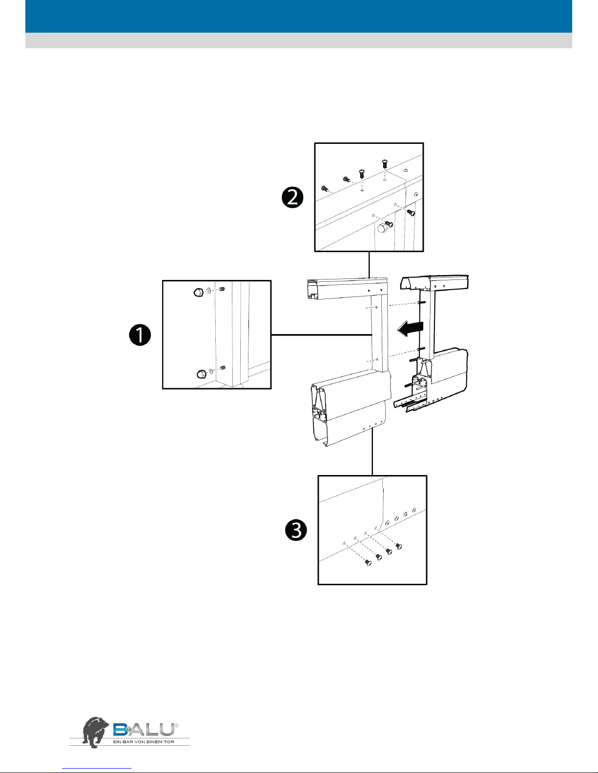
ENGLISH
22
8. Installation instructions for the connection of the 2-piece supply of
pillar lamps for gates above 10.5 m in width
Attention! Use shorter screws!

ENGLISH
23
Special instructions BALU ECO / PRIMO GREEN / PRIMO BLUE
9.

ENGLISH
24
10. Special instructions BALU ECO / PRIMO GREEN / PRIMO BLUE

ENGLISH
25
Special instructions
sliding gate motor – Colibri
Extern 60
Deimos BT D Prox MA

ENGLISH
26
11. Special instructions swing gate
Post anchor assembly
Post to be cemented
Manual swing gate
CB 1,3,4
Automatic system
CB 2
Automatic system

ENGLISH
27
Special instructions swing gate motor
Colibri + BALU
ZLJ14 für CB 1,3,4 - single leaf

ENGLISH
28
Special instructions swing gate motor
Colibri + BALU
ZLJ24 für CB 1,3,4 – two leaf

ENGLISH
29
Special instructions swing gate motor
Colibri + BALU
ZA3 für CB 2

ENGLISH
30

ENGLISH
31
12. Special instructions sliding gate motor INLINE 160 400V
Sheda Base ZT6

ENGLISH
32

ENGLISH
33
13. Declaration of Conformity and Perfomance
Declaration of Conformity and Performance
in accordance with the Machinery Directive 2006/42/EC, EN 1090, Construction Products Regulation of 2013
Company: HOLLER-TORE GmbH LEIBNITZ,
Dorfstrasse 31, A- 8430 Leitring
We certify herewith, at our sole responsibility, the conformity of the product
Sliding gate H-T B·ALU Industrie
H-T B·ALU ECO
Drive INLINE 100, INLINE 120, INLINE 160, INLINE 250
EXTERN 60, EXTERN 180
with the basic requirements of the following EC Directives:
EU Construction Products Directive 89/106/EWG,
EU Machinery Directive 2006/42/EC,
EU Low Voltage Directive 2006/95/EC
EU Electromagnetic Compatibility Directive 2004/108/EC
In particular, the following harmonised standards have been applied:
EN13241-1 Gates – Product standard, products without fire resistance or smoke control characteristics
EN 12100 Safety of machinery – Basic concepts and general principles,
EN 12445 Safety in use of power-operated gates, test methods,
EN 12453 Safety in use of power-operated gates, requirements,
EN 12978 Safety devices for power-operated doors and gates,
EN 414 Safety of machinery – Rules for the drafting and presentation of safety standards,
EN ISO 13850 Safety of machinery – Emergency stop equipment, functional aspects – Principles for design,
EN ISO 13849-1 Safety of machinery – Safety related parts of control systems,
EN 1037 Safety of machinery – Prevention of unexpected start-up,
EN 12100 Safety of machinery – Principles for risk assessment,
EN 60204-1 Safety of machinery – Electrical equipment of machines.
Leitring, 2013-01-11
Authorised signatory for documentation
Ewald Holler
Managing Director
14. General Terms and Conditions for Delivery and Sales

ENGLISH
34
General Terms and Conditions for Delivery and Sales by Holler-Tore GmbH, A-8430 Leitring, Dorfstrasse 31
1. Foreword
Holler Tore (Gates) accepts orders, sells and supplies only on the
basis of these terms and conditions of sales and delivery. The
following conditions are applicable t o all services that are
provided by Holler Tore or a subcontractor appointed by it in the
course of executing an order. Any amendments or s upplements
to this contract agreement that have been made verbally are
effective only if they have been confirmed by Holler Tore in
writing. Any business-related terms and conditions of the
customer are expressly excluded for the present legal transaction
and the entire business relationship. If any specific provisions
become ineffective, this shall not affect the rema ining terms and
conditions. All information regarding prices, weights, dimensions
or technical specifications etc. furnished in the documentation of
Holler Tore are binding only if reference is made to them
expressly. Technical specifications are subject to change.
2. Delivery of goods
The delivery takes place at the cost and risk of the customer.
Holler Tore is entitled to make pa rtial or advance deliveries and
to invoice the s ame. The customer must bring any complaints
immediately on receipt of the goods to the notice of the
transport company (end orsement on the consignment note) and
to Holler Tore in writing, at the latest within eight days. The
measures and costs incurred towards storage of the goods in safe
custody that become necessary on account of reasons
attributable to the customer, shall be borne by the customers,
and are deemed to be delivered as soon as the action for st orage
of t he goods commences. Factually just ified and reasonable
changes in the service and delivery obligations of Holler Tore,
particularly reasonable extensions in the delivery period, are
deemed to have been approved by the customer in advance.
Delivery schedules announced are considered to be merely
approximate estimates . Force Majeure conditions or other
unforeseeable hindrances attributable to Holler Tore or its subsuppliers absolve Holle r Tore from the obligation of complying
with the delivery schedule agreed to. The customer is obliged to
make arrangements to collect the goods stored at Holler Tore
promptly after being intimated by them to do so. Operational
and traffic disruptions and deliveries by sub-suppliers not in
accordance with the schedule are also applicable as Force
Majeure conditions and absolve Holler Tore for the period of
hindrance or, based on the choice of Holler Tore, even ultimately
from the obligation of delivery, without any claims becoming due
to the customers on accou nt of withdrawal by Holler Tore. Holler
Tore is free to choose the type of d ispatch of the goods and the
mode of transport. The place of performance for the delivery and
payment is the head office of Holler Tore.
3. Offer preparation and pricing information
The offers of Holler Tore, whether in writing, verbally or via
telephone, are applicable on ex-works bas is unless specified
otherwise. A purchase agreement is created if Holler Tore either
sends an order confirmation in writing or de livers the items
ordered out within the acceptance period of the agreement. In
general, the acceptance period is 4 weeks. All offers are nonbinding and subject t o confirmation. Holler Tore is not obliged to
accept the order.
4. Manufacturing tolerances and clearances
No liability is assumed for the quantities specified in the offers.
Holler Tore reserves the right to variations from specifications
given in brochures and samples in terms of colo ur, dimensions,
weights and quality. Provided that any deviations or variations
are, in any case, reasonable for the customer, particularly since
they are minor in nature and realistically justified, Holler Tore
may deviate from the products ordered as a result of production
tolerances. Technical specifications are expressly subject to
change.
5. Cost estimates
The cost estimate is prepared based on the best knowledge, but
no liability can be assumed for the correctness of the same. The
costs for the preparation of a cost estimate, provided that they
are incurred, are charged to the customer. All cost estimates can
only be issued in w riting. Provided that nothing else follows from
this, Holler Tore is bound to the cost estimate for a period of four
weeks.
6. Expenses for collection, sending reminders and encashment
In case of delay in payment, the cust omer is obliged to reimburse
all costs incurred by Holler Tore prior to legal proceedings, such
as lawyer's fees and costs of the collection offic e, provided that
these costs were necessary for the purpose of legal proceedings.
The customer is obliged to pay an amount of 15,- EUR fo r each
reminder, p lus the interest due at the rate of 14 % p.a. and all
other special costs incurred.
7. Guarantees, Warranties and Liabilities
For all products that are delivered to companies in the sense of
commercial law, the warranty period is limited to 1 year from the
date of delivery / acceptance. In case of any defect in the goods
delivered, the customer, to begin with, can only demand
improvement or replacement of the goods. Holler Tore
undertakes to make improvement to or replace the goods after
they are handed over by the customers within a reasonable
period of time, whereby the non-binding delivery period shall be
considered to be the respective reasonable period of time. The
development of the w arranty obligation agreed to is send &
return, for which the place of performance is the original place of
delivery. It is agreed that the customer must enforce his right and
warranty for movable and immovable items in accordance with
Article 9 33 of the ABGB (General Civil Code) within six months.
Over and above this, Holler Tore grants a guarantee for the
coating of profile parts (not aluminium die-cast p arts) of 15 years
(Holler Tore coating guarantee), but this is applicable only subject
to the following prerequisites: 1. Cleaning and servicing must be
done using only the maintenance and care products of Holler
Tore. Preservation must be done in a verifiable manner and in
such a way that the item under warranty is cleaned at least twice
a year with Holler Tore surface care by trained and authorised
personnel of Holler Tore as is finally impregnated with
impregnation agents of Holler Tore. 2. No improper treatment
should be done by the purchaser or any other third party. 3. The
product covered by warranty should not come into contact with
salts, water containing lime o r similarly proc ured immersion
agents, acids or alkalis. 4. Moreover, there should be no impact
of Force Majeure conditions (mechanical damage). The guarantee
is related only to the reimbursement of the material cost for the
repair. Regard less of his rights, the customer bears the onus of
expressly confirming the characteristics required of the items
ordered out as subject matter of the contract agreement.
Customarily presumed characteristics are the product
characteristics spec ified by the manufacturers provided that
those characteristics that can be made by p roper and purposeful
application of the product as well as the relevant EN and Austr ian
(OEN) standards. As far as the surface coating is concerned, it is
specifically agreed that the Austrian standard EN 12206-1 shall be
applicable. The work of settings on doors or gates with the design
of a non-continuous foundation does not represent any defect.
Regardless of his rights, the customer also bears the onus of
checking the confo rmity of the goods delivered by Holler Tore
with the order visually and immediately, as well as with the
product names and batch numbers specified at the t ime of their
delivery.
Claims for compensation made by the customer are basi cally
ruled out.. The liability for gross negligence or mal-intent to those
other t han consumers is limited to an amount that is twice the
net value of the goods. Any claim for compensation is ruled out in
case of non-compliance with our terms and conditions for
installation, commissioning or use. The customer must inform
Holler Tore promptly of any damage. Technical information from
Holler Tore is subject to change and requires w ritten
confirmation from Holler Tore provided that they go beyond the
scope of the manufacturer's specifications. Other than instances
for injuries to persons, claims for compensat ion by t he customer
on account of delayed delivery or withdrawal from the contract
agreement are excluded.
8. Payment terms
The invoice is raised, as far as possible, promptly after delivery.
Payments are due on the issue of the invoice without any delay
or deductions. Payment terms that have been specified and
agreed to for the entire order are also applicable to part invoices.
For orders that cover several units, Holler Tore is entitled to raise
an invoice after the delivery of each unit or item of service. The
customer is not entitled to retain payments on account of
incomplete deliveries, claims for guarantee or warranty or any
defects. Payments received from the customer by Holler Tore are
due for compound interest, interest and subsidiary expenses, and
costs prior to legal proceedings such as costs of engaging a
lawyer and collection office on the outstanding capital amount
starting from the oldest amount due. In case of delay in payment,
it is agreed that interest shall be charged on the delayed payment
at 14 % p.a. by BALU. In the event of default in two instalments
for pa rt payments, Holler Tore is entitled to have delay in
schedules to come into effect and to make any acceptance of
goods handed over as correspondingly due for payment. If the
customer is in default of payment such that a complaint can be
made for only one invoice of Holler Tore pending, it is agreed that
as far as all pending invoices of Holler Tore for this customer are
concerned, they become due for payment and any cash discounts
or other rebates become invalid. In case of non-compliance with
the payment terms of Holler Tore as well as justified concerns of
the payment capability of the purchaser (that is, with payments
that already been delayed), Holler Tore is entitled to retain any
deliveries or services that are outstanding, or to demand advance
payments or guarantees or to withdraw from the contract
agreement without setting any grace period.
9. Retention of title
The goods delivered remain in the unlimited ownership of Holler
Tore until the payment of all claims made by Holler Tore f or the
delivery (including interest payments and costs) has been made.
Hypothecations and assignments by way of security made by the
customer are excluded unless complete payment has been made.
If the customer does not comply with his obligations arising out
of the contract agreement that has been concluded, Holler Tore
is entitled to retrieve its property at any time at the cost of the
customer, and the customer expressly undertakes to issue the
same under these circumstances. If the goods delivered by Holler
Tore are still under their title and are hy pothecated or
confiscated, the customer undertakes to inform Holler Tore of
the same within three days and to issue all information necessary
to Holler Tore for the enforcement of its ownership rights. If third
parties access the goods standing in the ownership of Holler Tore
or enforce claims on them, the customer undertakes to bring to
the notice of those concerned, the fact that these goods are in
the ownership of Holler Tore. The enforcement of the title of
retention by Holler Tore does not represent any withdrawal on
the part of H oller Tore from the contract agreement. Deliveries
made for a particular construction project, even if are ordered
out, delivered and billed section-wise, are considered to be one
uniform order. In the event of delayed payment a s well as in case
of justified concerns reg arding the payment capability of t he
purchaser (payment that has already been delayed is sufficient
cause), Holler Tore is entitled to amended any agreements
arrived at so far with immediate effect unilaterally (discounts,
sales territories etc.), to collect goods un der their ownership
without withdrawing from the contract agreement. For all goods
taken back, the customer has to reimburse all costs incurred in
this connection with their transport and handling to Holler Tore.
10. Product liability
Demands for claims in the context of Artic le 12 of the Product
Liability Act are excluded unless the party authorised for recourse
establishes that the fault is attributable to Holler Tore and that
Holler Tore is culpable at least for gross negligence. Provided that
the customer is not a consumer in accordance with the KSchG
(Buyer Protection Act), the liability for damage to property arising
from a fault in the product is excluded as specified in Article 8 of
the Product Liability Act and, in fact, even for all companies
involved in the manufacture, import and sale. For this case, the
customer undertakes to transfer this exclusion of liability to his
buyers. As far as the sales of imported goods are concerned,
Holler Tore undertakes to notify the customer against a w ritten
request about the preceding endorser within 14 days.
11. Applicable law and jurisdiction
It is agreed that only the locally competent Court located in 8430
Leibnitz having t he jurisdiction shall preside over any disputes.
Austrian material law shall be applicable. The applicability of the
UN CISG (Convention on the International Sale of Goods) and the
reference st andards on the IPRG (Code on Private International
Law) is ruled out.
12. Assignment of claims
For delivery under retention of title, the customer assigns its
claims against third parties at this stag e to Holler Tore provided
that these arise as a result of sale or processing of our goods,
until final payment has been made against all our claims. This
cession must be made evident in the books of accounts,
consignment note, invoices, etc. to the buyer. If the customer is
default of payment to Holler Tore, the proceeds of sales received
by him need to be separated out in s uch a manner o r the
customer holds such payments only on behalf of Holler Tore. Any
claims from an insurance company need to be assigned to Holler
Tore at t his stage to the limits specified in the respective
Insurance Act. The customer is not entitled to adjust any counterclaims against Holler Tore against the claims made by Holler Tore.
An exception to this is only when these counter-cl aims have been
acknowledged by Holler Tore in writing.
13. Privacy policy declaration – Change in address
The customer grants his consent for the personal information
contained in the purchase agreement may be saved and
processed by Holler Tore for the purpose of fulfilling the contract
agreement. The customer is obliged to inform Holler Tore about
any amendments to his residential or business address provided
that the legal transaction pertaining to the contract agreement
has not been completed by both parties.
If this information is not furnished, declarations are deemed to
have been received even if they have been sent to the last known
address.
14. Final provisions
For the sale to consumers in the context of the Consumer
Protection Act, the provisions given above are applicable only if
the Consumer Protection Act does not foresee any other
provisions as being mandatory. Force Majeure conditions or
other unforeseeable hindrances in the scope of Holler Tore
absolve them from compliance with the obligations agreed to for
the period of the Force Majeure conditions. The customer
expressly dispenses with the right to challenge the terms and
conditions of sale and payment agreed to in the contract that has
been concluded, regardless of the reason, even on account of
reduction by more than half the actual value as well as on
account of a mistake.

ENGLISH
35
15. Test log for power-operated gates
_____________________________________
Designation
Type of the gate: _______________________
Company: _____________________________
Location: ______________________________
1. Principles for testing power-operated gates
The safety-related requirements and test procedures for the construction and
equipment of power-operated gates have been specified in the European standards,
which furnish the specific details of the general requirements of the European
Machinery Directive.
In particular, these include:
• DIN EN 12604 Industrial, commercial and garage doors and gates: mechanical
aspects; requirements
• DIN EN 12605 Industrial, commercial and garage doors and gates: mechanical
aspects; test methods
• DIN EN 12453 Industrial, commercial and garage doors and gates: safety in use
of power-operated doors; requirements
• DIN EN 12445 Industrial, commercial and garage doors and gates: safety in use
of power-operated doors; test methods
• DIN EN 12635 Industrial, commercial and garage doors and gates: installation
and use
According to BGR 232, section 6, power-operated doors and gates must be tested by
a competent person before it is put into operation for the first time and as needed,
but at least once a year. This testing is not equivalent to maintenance. A competent
person is one who, based on his technical education and experience, has adequate
knowledge in the field of power-operated gates and is conversant with relevant
national regulations on occupational safety, accident prevention and general best
engineering practices (e.g. BG regulations, DIN standards and VDE provisions) to such
an extent that he can assess the safe condition of such gates and doors. Such persons
include, e.g. experts, manufacturer's specialists, companies providing delivery and
assembly services or specialists of the operating agency having relevant experience.
Professional experts need to issue their assessment from the viewpoint of
occupational safety, without being influenced by other, for example, economical
circumstances. The outcome of the testing must be recorded in writing. The written
certificate should be kept ready at hand at the place where the power-operated
gates are being operated for inspection. National requirements of the installation
and testing must also be observed and followed!
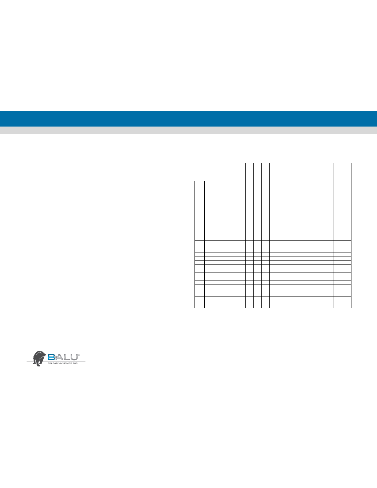
ENGLISH
36
2. System data
1. Address of the operating agency: _______________________________________
______________________________________
Place where the system is operated: _______________________________________
2. Designation: _________________________________________ Type: ______
Serial number: _________________________ year of manufacture: __________
Comissioned on: _______________________
3. Wing
Manufacturer or supplier: ______________________________________________
Dimensions: ____________________________ Material: ____________________
Wing filling: _________________________________________________________
4. Drive
Manufacturer or supplier: ______________________________________________
Type: _______________________________ Power: ________________________
Operating voltage: ____________________ Control voltage: _________________
5. Control
Type of control (e.g. button, dead-man's control, remote control, light barrier,
hand-held transmitter or induction loop): _________________________________
____________________________________________________________________
6. Safety mechanism of the main locking edge
Switching bar, locking edge security and force restriction
Contact-less safety devices, e.g. light grid, light barrier or radar
Miscellaneous: _______________________________________________________
7. Additional safeguards against damage to property (e.g. light barrier in the
passageway)
8. Other information: ___________________________________________________
____________________________________________________
3. List of testes for power-operated sliding gates
Designation: _________________________________________
Type: _______________________________________________ Serial number: ____________________
Year of manufacture: __________________________________ Supplier: _________________________
Colour: _____________________________________________ Motor type: ______________________
OK
recommen
ded
not
present
OK
recommen
ded
not
present
0.0
Basic testing
3.0
Control
0.1
Visual impression
3.1
Control elements, push
buttons, key switches
0.2
Test opening
3.2
Limit switches
0.3
General functionality
3.3
Emergency stop buttons
0.4
Nameplate
3.4
Equipment for remote control
0.4
CE marking
3.5
Inductions loops
1.0
Mechanical System
4.0
Safety mechansim
1.1
Wing, wing filling
4.1
Electrical switching rails
1.2
Guides, runner rails, bars
and stops
4.2
Force restriction
1.3
Rollers, roller mechanisms
and covers
4.3
Dead-man’s control
1.4
Suspension of the wing
4.4
Contact-less safety equipment
and devices
4.5
Safety clearances between the
wing and fixed items in the
surrounding area
5.0
Test findings
2.0
Drives
2.1
Drive fixture
2.2
Air-tightness of the gearbox
housing
2.3
Braking effect, trailing
distance
2.4
Slip clutch
2.5
Condition of the electrical
lines and connections
2.6
Power transmission (pinion)
2.7
Mechanism for manual
operation
2.8
decoupling
Test conducted on: ___________________________________
Schedule fort he next test: ___________________________________
____________________________ ________________________
Test person’s signature Customer’s signature

ENGLISH
37
4. Supplementary declaration of the assembly
(Supplement to the declaration of conformity of the manufacturer / distributor)
The company ______________________________________________________
Name ______________________________________________________
Adress ______________________________________________________
______________________________________________________
______________________________________________________
herewith declares that it complies with all assembly specifications in accordance with
the installation manual or the operation manual of the gate manufacturer, as well as
proper and professional installation using installation material that is appropriate to
the place of installation or the subsoil present there.
The person signing this declaration is ___________________ (*) of the company.
(*) e.g. proprietor, shareholder or Managing Director (CEO)
_________________ _________________ ______________________
Place Date seal and signature
5. Handing over and instructions on use
(Data about the system in accordance wirth clauses 2,3 and 4 of the declaration)
Persons present who have been trained and instructed on the gate system:
________________________________________ ________________________________________
Name Unterschrift
________________________________________ ________________________________________
Name Unterschrift
________________________________________ ________________________________________
Name Unterschrift
________________________________________ ________________________________________
Name Unterschrift
Pulse encoder demonstraded: Yes No
Hand-held transmitter handed over: Yes No
Keys handed over: Yes No
Safety equipment and devices demonstrated: Yes No
Emergency locking system demonstrated and attention drawn to the fact that locking and unlocking
shouldbe done only when the system is at standstill: Yes No
Outputs on the display explained: Yes No
Briefing given on the maintenance intervals: Yes No
___________________________________________________________
Place / date when system handed over
Technical documentation handed over: Yes No Ort / Datum der Anlagenübergabe
___________________________________ ___________________________________
Signature fitter signature system operator

ENGLISH
38
Notes

FRANÇAIS
1
Mode d’installation et d’emploi

FRANÇAIS
1
Instructions pour l'installateur et l'utilisateur final
Cher client,
Nous sommes heureux que vous ayez décidé d'acheter notre portail. Ces instructions de montage et d'exploitation contiennent toutes les
informations nécessaires pourcomprendre le fonctionnement du produit. Nous vous demandons de lire attentivement les instructions de
ce manuel avant de commencer à travailler sur ce produit.
Le montage doit être effectué uniquement par du personnel autorisé. La table des matières doit vous aider à récupérer les informations
nécessaires dans le manuel.
Les règles et règlements propres à chaque pays doivent être respectés!
Pour nous joindre :
Clause de non-responsabilité
Ce portail doit seulement être utilisé pour la fermeture dynamique de passages.
Holler-Tore décline toute responsabilité pour les dommages causés par un usage impropre, mauvais ou non autorisé. Veuillez lire
attentivement ces instructions.
Holler-Tore se réfère au marquage CE apposé en ce qui concerne la fabrication des portails.
Nous offrons également toute la documentation technique et un guide de montage et d'utilisation
Ces portails sont conformes aux spécifications de normalisation EN 13241-1. Certaines exigences s'appliquent aussi au montage du portail,
les instructions de montage doivent être respectées à tout moment et le montage doit être effectué uniquement par installateur autorisé
BALU, en tenant compte des dispositions légales et des règlements applicables. La sécurité doit être assurée en tout temps, afin que les
utilis-ateurs et les tiers puissent utiliser le portail coulissant en toute sécurité. L'installateur est responsable de la bonne installation. En cas
de questions ou d'incertitudes concernant le montage, l'installateur peut s'adresser à Holler-Tore pour de plus amples renseignements.
Sommaire
1. Précautions et avertissements ......................................................................................................................................................................................... 2
2. Spécifications techniques ................................................................................................................................................................................................ 3
3. Montage, installation et mise en service ........................................................................................................................................................................... 6
4. Description de la commande et de l’utilisation ................................................................................................................................................................ 12
5. Entretien et plan de maintenance .................................................................................................................................................................................. 14
6. Environnement, démontage, stockage et transport ......................................................................................................................................................... 15
7. Instrucions de programmation ....................................................................................................................................................................................... 15
8. Notice de montage connexion livraison en deur parties pour les portails de plus de 10,5 m lumière du poteau .................................................................. 22
9. Instructions Speciales BALU ECO ................................................................................................................................................................................. 23
10. Instructions Speziales Colibri ....................................................................................................................................................................................... 24
11. Portail Pivotant ............................................................................................................................................................................................................. 26
12. Inline 160..................................................................................................................................................................................................................... 31
13. Déclaration de conformité et perfomance ...................................................................................................................................................................... 33
14. Déclaration de conformité ............................................................................................................................................................................................. 34
15. Registre de contrôle pour portails motorisés .................................................................................................................................................................. 36

FRANÇAIS
2
1. Précautions et avertissements
INDICATIONS IMPORTANTES:
Avant le début des travaux de montage, remettre un guide de montage et d'utilisation à l'utilisateur, l'initier à l'utilisation et
contrôler le fonctionnement correct du portail et de la colonne avant de commencer le montage.
Sécuriser la zone de travail avant et pendant le montage pour empêcher un accès non autorisé. Prendre en compte la sécurité
publique en tenant compte des circon-stances. Surtout lorsque l'on travaille à proximité des écoles, la sécurité des enfants doit
être tout par-ticulièrement prise en compte.
Pour le transport de charges lourdes, toujours utiliser seulement des appareils de levage agréés. Lors de l'e-xécution de travaux
de levage, toujours travailler avec plus d'une personne, même lorsque des aides de levage sont utilisées. Le poids maximal d'une
charge à trans-porter par un individu ne doit pas dépasser 25 kg.
Toujours porter l'équipement de protection individuelle nécessaire, tel que gants de protection, des chaussures de sécurité (au
moins de classe S3), des lunettes de sécurité, une protection auditive, un masque antipoussière et une salopette.
Tous les travaux de montage doivent être effectués par une installateur autorisé BALU. L'installateur est tenu de veiller à utiliser
un personnel qualifié ayant une expérience adaptée.
Les déchets doivent être conservés séparément. Renseignez-vous sur les opportunités régionales pour une élimination sûre et
correcte.

FRANÇAIS
3
2. Spécifications techniques
2.1. Spécification générale du produit
BALU Manuel
Dimension de la colonne: 150 x 150 mm
BALU Inline 100
Largeur du portail maxi: 10m
Poids maximal du portail: 700 kg
ED: 70 %
Niveau de Bruit: < 80 dB (A)
Raccordement au rèseau: 230 V
Tension d’alimentation du moteur: 24 V
Dimension de la colonne: 220 x 170 mm
BALU Inline 120
Largeur du portail maxi: 12 m
Poids maximal du portail: 1.000 kg
ED: 70 %
Niveau de Bruit: < 80 dB (A)
Raccordement au rèseau: 230 V
Tension d’alimentation du moteur: 24 V
Dimension de la colonne: 220 x 170 mm
BALU Extern 180
Largeur du portail maxi: 18 m
Poids maximal du portail: 2.000 kg
ED: 70 %
Niveau de Bruit: < 80 dB (A)
Raccordement au rèseau: 230 V
Tension d’alimentation du moteur: 24 V
Dimension de la colonne: 150 x 150 mm
BALU Inline 160
Largeur du portail maxi: 16 m
Poids maximal du portail: 1.300 kg
ED 80 %
Niveau de Bruit: < 80 dB (A)
Raccordement au rèseau: 400 V
Tension d’alimentation du moteur: 400 V
Dimension de la colonne: 220 x 170 mm
BALU Inline 250
Largeur du portail maxi: 25 m
Poids maximal du portail: 3.000 kg
ED 100 %
Niveau de Bruit: < 80 dB (A)
Raccordement au rèseau: 230 V
Tension d’alimentation du moteur: 230 V
Dimension de la colonne: 220 x 170 mm

FRANÇAIS
4
2.2. Outils nécessaires
Bêche
Truelle
Perforatrice de 18 mm
Brosse d’alésage
Pompe à air
Cartouches de colle M 16
Clé Allen 6 et 8
Niveau à bulle d’air
Clé à douille SW 17 et 24
Vis, écrous et inserts M 16

FRANÇAIS
5
2.3. Die wichtigsten Bauteile
2.3.1. Manuell
2.3.2. Inline
2.3.3. Extern

FRANÇAIS
6
80 cm
3. Montage, installation et mise en service
3.1. Généralités
Sécuriser la zone de travail avant et pendant les travaux de montage pour
empêcher
un accès non autorisé. La sécurité des tiers doit être assurée.
Toujours porter l'équipement de protection individuelle nécessaire, tel que gants
de protection, des chaussures de sécurité (au moins de classe S3), des lunettes de
sécurité, une protection auditive, un masque antipoussière et une salopette.
ATTENTION ! Tous les travaux de montage doivent être effectués par une main-d'œuvre qualifiée et
compétente.
3.2. Prépare the ground
ETAPE 1
S'assurer que
l'ensemble de la
zone de travail pour
le portail est libre de
tout obstacle.
Le placement sur la
maçonnerie
existante résulte du
plan de fondation.
ETAPE 2
1. Préparer le passage du
câble et éventuellement
les accessoires.
2. Définir la position zéro
du portail et fabriquer le
coffrage pour la
fondation.
3. Utiliser un coude
progressif spécial pour rétracter le tubage vide. La partie horizontale
du coude et le tuyau vide doivent être à au moins 80 cm en dessous
de la surface du sol.
ETAPE 3
Remplir le coffrage
avec du béton.
Laisser reposer le
béton jusqu'à
durcissement
complet et selon les
spécifications du
béton.
ETAPE 4
Maintenant, marquer les
trous pour le montage de
la colonne sur la
fondation. Pour les trous,
utiliser une perceuse de
18 mm.
Attention: ne pas encore
mettre en place les trous
pour le portail d'entrée et les rouleaux d'accès arrière!
ETAPE 5
1. Nettoyer les trous
2. Enlever les restes
de poussière et de
saleté des trous avec
une pompe à air
3. Utiliser des
cartouches de colle
ETAPE 6
Maintenant, insérez les
vis sans tête dans les
trous avec un
mouvement de rotation.
Les extrémités des vis
sans tête doivent
dépasser d'au moins 60
cm au-dessus de la
fondation.
Laisser durcir les ancrages adhésifs selon la spécification
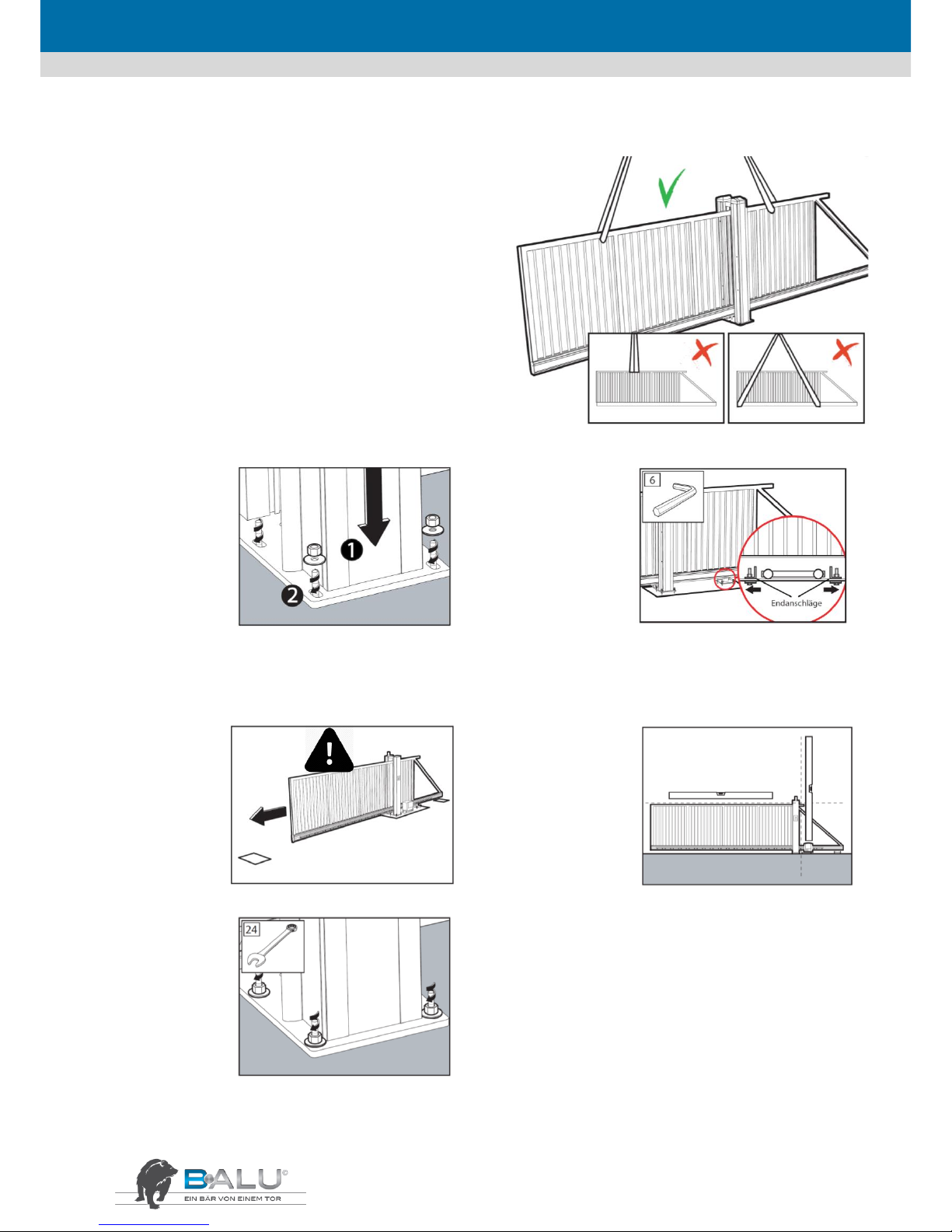
FRANÇAIS
7
3.3. Mettre en place le portail coulissant
Pour le transport de charges lourdes, toujours utiliser seulement
des appareils de levage agréés. Lors de l'exécution de travaux de
levage, toujours travailler avec plus d'une personne, même lorsque
des aides de levage sont utilisées. Le poids maximal d'une charge à
lever par un individu ne doit pas dépasser 25 kg.
ATTENTION ! Utilisez un appareil de levage d'une puissance
suffisante. La limite de charge de sécurité est toujours indiquée sur
l'appareil de levage. Lever le portail de façon incorrecte peut
entraîner une déformation du portail. (sécuriser la colonne
d'entraînement !)
ATTENTION ! Veiller à bien répartir la charge lorsque vous soulevez
des portails ! Les bretelles de soutien doivent avoir une limite de
charge suffisante et ne peuvent être effilochées. Veiller à
suffisamment protéger le portail ! Ne pas utiliser de chaines !
ETAPE 1
1. Abaisser les
colonnes via les
extrémités des tiges
filetées.
2. Mettre en place les
inserts et les écrous
et les serrer à la
main.
ETAPE 2
1. Repousser les butées
de fin de course, avec
lesquelles le portail est
sécurisé pendant le
transport, vers
l'extérieur. Ne jamais
retirer les butées de fin
de course!
2. Pour les portails à commande électrique, débloquer le moteur
selon le manuel du moteur.
3. Serrer les butées de fin de course dans les bonnes positions, de
telle sorte que le portail s'ouvre et se ferme en affleurement.
ETAPE 3
Mettre le portail en
position fermée.
S'assurer que le
passage est libre de
tout obstacle !
Risque
d’écrasement!
ETAPE 4
Niveler verticalement ou
horizontalement la colonne
et le portail avec les écrous
sur les tiges filetées par
rapport à la plaque de base
en utilisant le niveau à bulle
d'air.
ETAPE 5
Bien serrer tous les
écrous.

FRANÇAIS
8
3.4. Placement de la colonne
ETAPE 1
S'assurer que le portail se
trouve en position
fermée et détermine la
position de la colonne
d'entrée.
ETAPE 2
Marquer les trous pour la
fondation. Pour ce faire,
utiliser la place de base
comme modèle. Ouvrir
légèrement le portail. Retirer
la colonne d'entrée et
pratiquer des trous avec une
perceuse de 18 mm.
ETAPE 3
1. Nettoyer les trous
avec une brosse.
2. Nettoyer les trous.
S'assurer que tous les
débris de poussière
et de saleté ont été
enlevés.
3. Utiliser des
cartouches de colle.
ETAPE 4
Mettre en place les tiges
filetées dans les trous
avec un mouvement de
rotation. Les extrémités
des tiges filetées doivent
dépasser d'au moins 60
cm au-dessus de la
fondation.
Laisser durcir les ancrages
adhésifs selon la spécification.
ETAPE 5
1. Abaisser le portail d'entrée audessus des tiges filetées.
2. Mettre en place les inserts et les
écrous et serrer ceux-ci à la main
ETAPE 6
1. Fermer le portail
jusqu'à ce que les
rouleaux d'accès
viennent se placer à
fleur contre le bord
inférieur de la poutre
inférieure.
2. Régler la hauteur
d'entrée de telle sorte
que la distance entre le portail et l'accès soit d'au moins 5 mm. Un
mauvais réglage augmente le risque de dysfonctionnement dû à une
puissance d'entrée trop grande.
ETAPE 7
Niveler le portail
d'entrée avec le niveau
à bulles d'air et vérifier
le parallélisme de la
colonne et du portail.
ETAPE 8
Bien serrer tous les écrous.
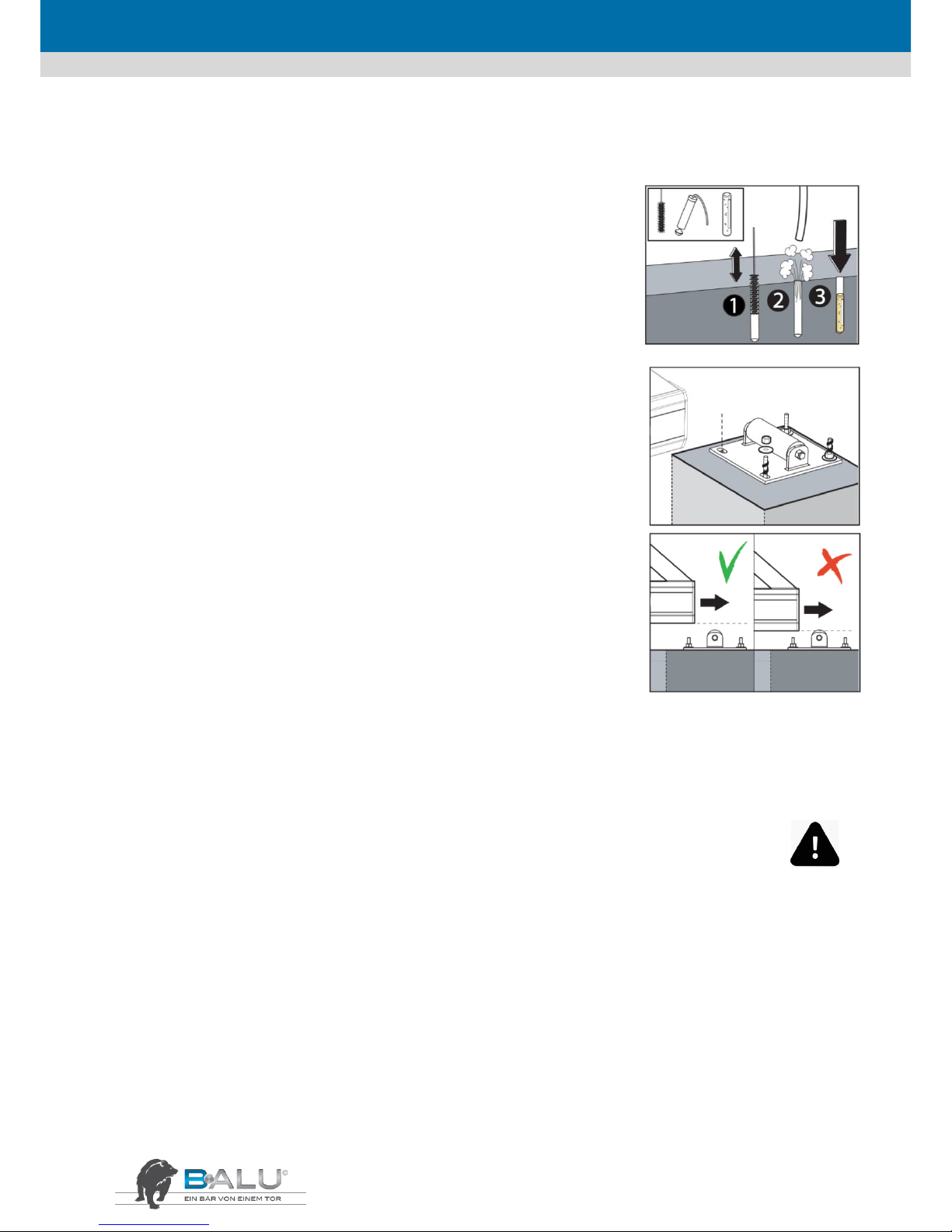
FRANÇAIS
9
3.5. Placement du rouleau d’accès arrière
ETAPE 1
Marquer les trous sur la fondation (position en fonction du plan de fondation). Utiliser la plaque
de base comme modèle. Retirer les rouleaux d'accès arrière et pratiquer des trous avec une
perceuse de 18 mm.
1. Nettoyer les trous avec une brosse.
2. Nettoyer les trous. S'assurer que tous les débris de poussière et de saleté ont été enlevés.
3. Utiliser des cartouches de colle.
ETAPE 2
Poser les tiges filetées et laisser durcir les ancrages adhésifs selon la spécification. Mettre en place
les rouleaux d'accès arrière, les inserts et les écrous et serrer à la main.
ETAPE 3
Ajuster les rouleaux d'accès arrière. À l'ouverture, le rouleau d'accès arrière ne doit pas toucher le
portail.
ATTENTION! Le portail ne peut pas être forcé à glisser sur les rouleaux d'accès arrière! Sans quoi le
portail pourrait être en-dommagé.
Régler la hauteur du rouleau d'accès arrière en tournant les écrous. Bien serrer les écrous avec
une clé à vis.
3.6. Installation électrique
3.6.1. Généralités
ATTENTION ! Ces travaux de montage doivent être effectués par un électricien qualifié et compétent conformément aux
règlements et dispositions en vigueur.
ATTENTION ! Risque d'écrasement et risque de décharge électrique!
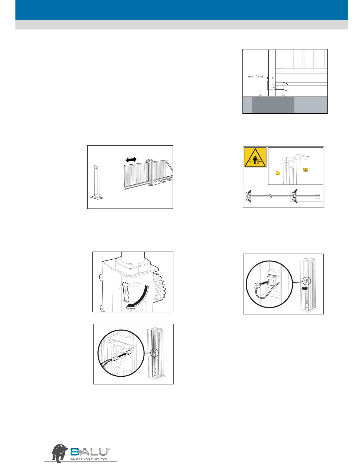
FRANÇAIS
10
3.6.2. Inline
ETAPE 1
Mettre en place les barrières photo-électriques de la colonne
d'entrée. Connecter les barrières photo-électriques au moteur
par câble.
ETAPE 2
Vérifier à nouveau si la
butée de fin de course
est dans la bonne
position : le portail doit
être en mesure de
s'ouvrir et se fermer
complètement, mais de
telle sorte que le profil
de contact de sécurité se
trouve à dix millimètres avant la face arrière de l'accès.
ATTENTION ! Risque d’écrasement!
ETAPE 3
ATTENTION!
Danger de mort
par
électrocution!
1. Contrôler si
l'installation est
sous tension.
Ensuite, branchez
le cordon d'alimentation de la colonne de guidage à la prise
mura-le selon les règles applicables.
2. Mettre le portail en position centrée.
3. Retirer le couvercle de la commande dans la colonne de
guidage et vérifier les fusibles.
ETAPE 4
Fixer les étiquettes
d'avertissement
ETAPE 5
Enclencher le moteur
et mettre le portail en
position fermée.
ETAPE 6
1. Brancher la fiche de
réseau dans la prise
murale.
2. Une fois le portail
fermé, procéder à la
programmation du
moteur conformément
aux instructions.
STEP 7
1. Contrôler si toutes
les pièces
fonctionnent
correctement.
2. Ouvrir la colonne de
guidage via la serrure
sur le côté extérieur
de la colonne.
3. Insérez le
connecteur de la batterie dans la prise J1 en haut à droite de la
platine de commande.
ATTENTION! Le portail fonctionne également en mode accu
lorsque le courant du secteur est coupé -risque d'écrasement en outre, en position de repos, débrancher le connecteur de la
batterie!

FRANÇAIS
11
3.6.3. Extern
ETAPE 1
1. Positionner
correctement la
crémaillère par
rapport au pignon du
moteur. Le jeu de
réglage doit être
minimum.
2. Le réglage de la crémaillère par rapport au pignon du Moteur
devra être contrôler sur toute la longueur
3. La crémaillère ou le(s) chariot(s) de roulement devront être
ajusté(s) s'il y à trop de jeu.
ETAPE 2
Mettre en place les
barrières photoélectriques de la colonne
d'entrée. Connecter les
barrières photoélectriques au moteur par
câble.
ETAPE 3
Vérifier à nouveau si
la butée de fin de
course est dans la
bonne position : le
portail doit être en
mesure de s'ouvrir et
se fermer
complètement, mais
de telle sorte que le
profil de contact de sécurité se trouve à dix millimètres avant la
face arrière de l'accès.
ATTENTION! Risque d’écrasement!
ETAPE 4
ATTENTION! Danger de
mort par électrocution!
1. Contrôler si
l'installation est sous
tension. Ensuite,
branchez le cordon
d'alimentation de la
colonne de guidage à la
prise murale selon les
règles applicables.
2. Mettre le portail en position centrée.
3. Retirer le couvercle de la commande dans la colonne de guidage
et vérifier les fusibles.
ETAPE 5
Fixer les étiquettes
d'avertissement
ETAPE 6
Verrouillage du moteur:
1. Tourner la manette dans le sens contraire
aux aiguilles d’une montre de façon à
embrayer le réducteur.
2. Fermer la couvre-manette, tourner la clé
dans le sens des ai-guilles d’une montre et
pivoter la plaquette. À ce point, le réducteur
est embrayé, et le portail est prêt à la manoeuvre.
Une fois que le fonctionnement normal du système a été rétabli,
ranger la clé à un endroit sûr
ETAPE 7
1. Brancher le contact
d'arrêt dans la boîte de
sortie de câble. Le
portail doit
maintenant être
déplacé en position
fermée.
2. Une fois le portail
fermé, procéder à la programmation du moteur conformément
aux instructions.

FRANÇAIS
12
4. Description de la commande et de l’utilisation
4.1. Généralités
ATTENTION ! Ne glisser aucun objet entre les pièces du portail, ne pas placer d'objets sur celui-ci ni au-dessus de celui-ci pendant que le portail est en mouvement.
Toujours se tenir à distance du portail pendant qu'il est en mouvement!
Se tenir sur le portail en mouvement est interdit !!
4.2. Mise hors circuit du portail
4.2.1. Inline
ETAPE 1
Ouvrir la colonne via
la serrure se trouvant
sur sa face externe.
Pour interrompre
l'alimentation vers
l'automatisme pour
portail, retirer
d'abord la fiche de la
prise murale, puis prendre le connecteur de la batterie de la
carte de circuit.
ATTENTION! Danger de mort par électrocution!
ETAPE 2
1. Déverrouiller le
dispositif de verrouillage
entre le portail et le
moteur en utilisant le
levier de déverrouillage
d'urgence sur le moteur.
2. Le portail peut
maintenant être réglé à la
main.
ATTENTION! Vérifiez l'absence de tension du produit !
En déplaçant le portail à la main, tenir compte du risque
d'écrasement possible pour les personnes, les animaux et les
objets !
4.2.2. Extern
ETAPE 1
Ouvrir la colonne via
la serrure se trouvant
sur sa face externe.
Pour interrompre
l'alimentation vers
l'automatisme pour
portail, retirer d'abord
la fiche de la prise
murale, puis prendre
le connecteur de la batterie de la carte de circuit.
ATTENTION! Danger de mort par électrocution!
ETAPE 2
Déverrouillage
1. Faire pivoter la plaquette couvrant la
serrure, engager la clé, la tourner d’un demitour dans le sens contraire aux aiguilles d’une
montre et ouvrir la couvre-manette; à ce point,
il est pos-sible d’agir sur la manette pour le
déverrouillage.
2. Tourner la manette dans le sens des aiguilles d’une montre
jusqu’à l’arrêt. Attention! Ne pas forcer la manette en la tour-nant
au-delà de l’arrêt. Cette opération débraye le réducteur, et permet
la manoeuvre manuelle du portail
ATTENTION! Vérifiez l'absence de tension du produit!
En déplaçant le portail à la main, tenir compte du risque
d'écrasement possible pour les personnes, les animaux et les
objets!

FRANÇAIS
13
4.3. Réglage du produit
Réglez le produit selon vos exigences spécifiques d'utilisation. Ainsi, il est par exemple possible de régler le portail sur le mode automatique
ou semi-automatique - le temps de pause peut être réglé et l'entrée piétonne peut également être activée. Les informations sur ces
paramètres se trouvent dans les instructions de l'entraînement avec commande.
4.4. Utilisation
Assurez-vous que le portail fonctionne correctement à l'ouverture et à la fermeture.
Une description détaillée par ex. pour la programmation de la télécommande se trouve dans les instructions fournies pour l'entraînement
avec commande.
Attention ! Chaque fois que le portail est réglé sur le mode de fonctionnement « Fermeture automatique », une analyse spéciale des risques
doit être effectuée avant l'activation.
Déverrouiller le portail en cas de panne de courant en utilisant la poignée de verrouillage sur le moteur et régler le portail manuellement.
STEP 1
Utiliser la touche gauche de la télécommande pour ouvrir complètement le portail. Si le portail est
programmé en mode semi-automatique, le bouton-poussoir gauche doit être utilisé pour fermer le
portail.
STEP 2
Utilisez le bouton-poussoir droit de la télécommande pour la fonction porte de service. Si le portail
est réglé en mode semi-automatique, le bouton-poussoir gauche doit aussi être utilisé pour fermer
le portail
.
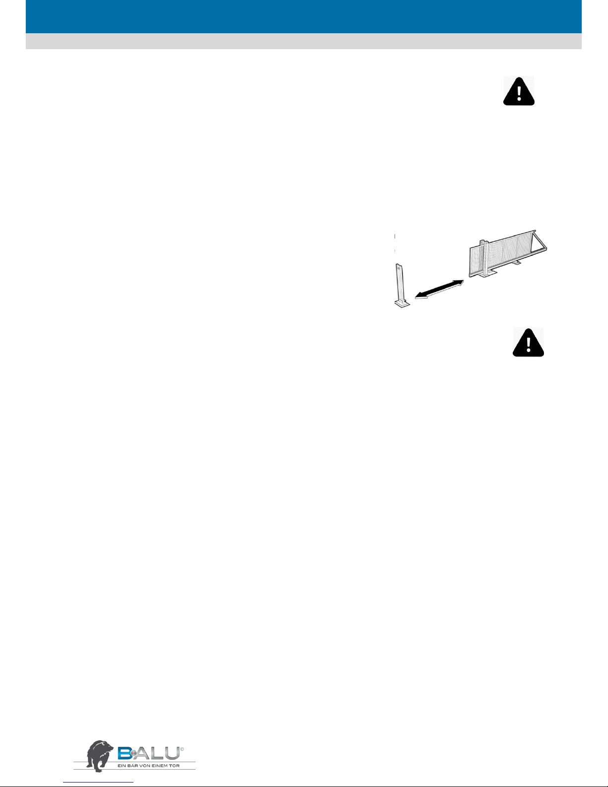
FRANÇAIS
14
5. Entretien et plan de maintenance
5.1. Généralités
ATTENTION! Ces travaux doivent être effectués par un technicien qualifié et compétent, conformément à la réglementation en vigueur et
aux dispositions légales.
ATTENTION! Toujours mettre l'appareil hors tension avant l'exécution des travaux d'entretien sur la colonne de guidage et le portail
d'entrée.
5.2. Entretien quotidien
Gardez à tout moment l'ouverture du portail dégagée de tout obstacle sur toute la plage de
fonctionnement!
5.3. Entretien mensuel
ATTENTION! Lors de l'entretien, toujours avoir à l'esprit le risque d'écrasement et la possibilité d'une décharge électrique!
ETAPE 1
Tester régulièrement tous les dispositifs de sécurité.
Ce portail est équipé de divers dispositifs de sécurité. Pour prévenir les accidents dus au portail, le fonctionnement correct de tous les
dispositifs de sécurité doit être vérifié régulièrement.
• Mettre le portail en position ouverte; appuyez la paume de la main contre l'un des patins de pression. Le portail doit s'arrêter
immédiatement. Répéter cette opération avec les autres patins de pression.
• Nettoyer les barrières photo-électriques avec un chiffon doux une fois par mois. Ensuite, fermer le portail et avec la main, passer dans la
zone comprise entre les barrières photo-électriques. Le portail doit s'arrêter immédiatement et reculer.
• Vérifiez le bon fonctionnement du feu clignotant sur la colonne
ETAPE 2
Une fois par mois, nettoyez l'intérieur du longeron inférieur. Cela empêche la saleté de pénétrer dans le guidage et empêche le portail de se
bloquer en cours de fonctionnement.
• Pour cela, mettre le portail en position fermée.
• Débranchez l'alimentation électrique.
• Essuyer le longeron inférieur avec un chiffon et éliminer ainsi les contaminants de l'intérieur.
• Allumer à nouveau l'alimentation et vérifier le bon fonctionnement du portail.
5.4. Une fois per an
ETAPE 1
S'assurer que le portail coulissant est entretenu une fois par an par des professionnels autorisés.
ETAPE 2
Une fois par an, remplacer les piles du profil de contact de sécurité sur l'arête de fermeture principale du portail.
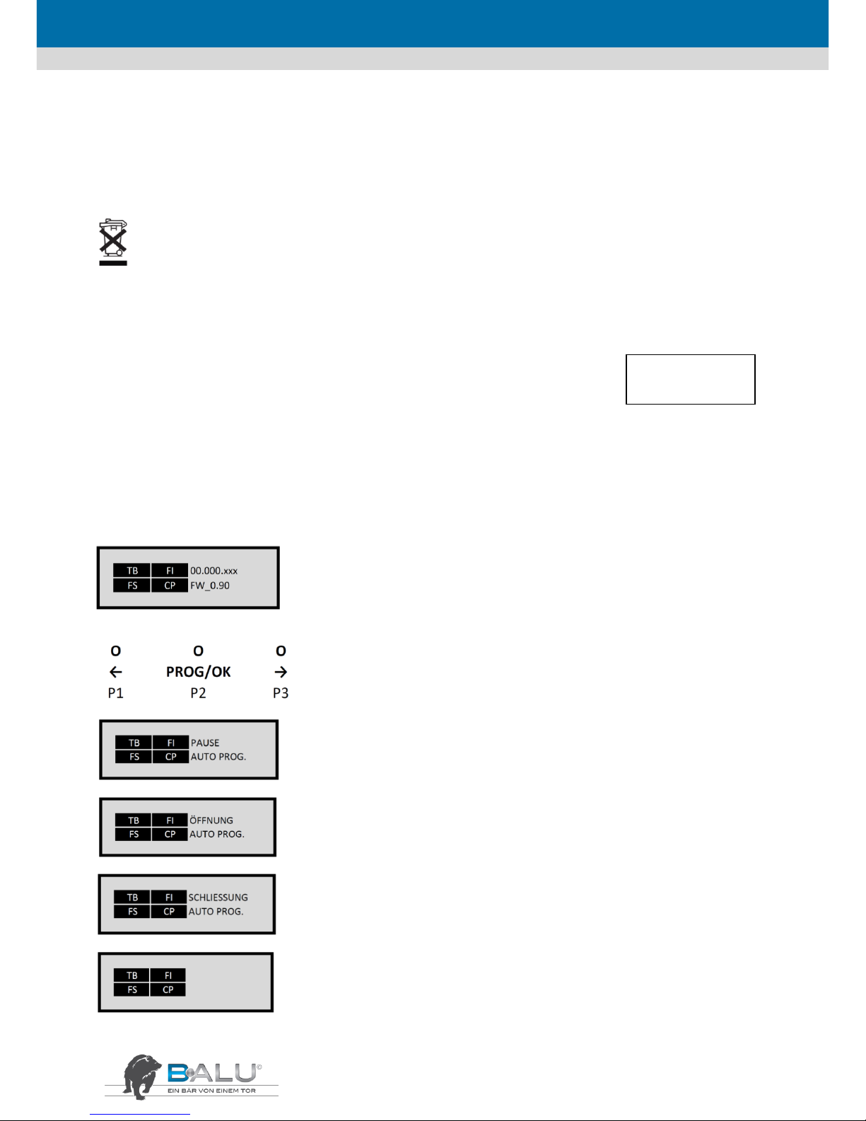
FRANÇAIS
15
6. Environnement, démontage, stockage et transport
6.1. Environnement-démontage
Éliminer le produit exclusivement par l'entremise d'une société de gestion des déchets autorisée !
Le démontage doit uniquement être effectué par du personnel qualifié!
6.2. Stockage et transport
Si le produit est destiné à être stocké ou transporté, il faut veiller au bon emballage. Le stockage doit avoir lieu dans un local sec.
7. Instructions de programmation
7.1. Mise en services rapide
Le portail est expédié à partir de l'usine avec les paramètres les plus importants et peut être personnalisé en quelques minutes :
Vérifiez qu'avant la programmation, les butées mécaniques existent et sont réglées en ouverture et fermeture. Celles-ci sont déplacées vers
l'unité pour la protection pendant le transport.
ATTENTION: Pendant la procédure d'apprentissage, la mise hors circuit est coupée. Par conséquent, assurez-vous qu'il n'y a pas de
personnes ni d'objets dans la zone de danger pendant la course d'apprentissage. S'assurer qu'aucune commande de démarrage ni d'arrêt
n'est donnée pendant la course et que les barrières photo-électriques ne sont pas interrompues.
Touches:
INLINE 100
INLINE 120
Affichage standard en présence de tension de réseau
Voyants permanents: tout est OK
Scintillement: Panne
Maintenez la touche P2 « PROG/OK » appuyée pendant
au moins 4 secondes
Appuyer 2x sur la touche P2 « PROG/OK ». Le portail s'ouvre
jusqu'à la butée interne, contrôle celle-ci et l'enregistre.
Le portail se ferme automatiquement jusqu'à la butée
interne, contrôle encore celle-ci et l'enregistre.
La commande a ainsi enregistré la position finale et les forces
de fonctionnement nécessaires. Si «PROGRAM» clignote à
l'écran, la course d'apprentissage doit être redémarrée

FRANÇAIS
16
7.2 Affectation des bornes
1 – 2
MOT
Raccordement moteur (effectué en usine)
3 – 6
ENC
Raccordement de L’encodeur (3 – bleu / 4 – vert / 5 – gris / 6 – jaune) (effectué en usine)
7
LCK
Déverrouillage de secours (affichage sur l’écran « moteur libre »)
8
CMN
Raccordement commun
9 – 10
LC/CH2
Raccordement d'une lumière ambiante alimentée par une source externe (max. 30 V ac/dc, 1A)
ou prise de tension 2. Canal radio (contact de commutation sans potentiel)
11
CMN
terminaison commune
12
LP
Feux clignotants (24 V dc/max. 25 W clignotants ou 12,5 W permanents)
13
LS
Témoin lumineux « portail ouvert » (24 V dc/max. 3 W)
clignote lentement pendant l'ouverture, clignote rapide pendant la fermeture
éclaire en permanence si la fermeture du portail est bloquée
s'éteint lorsque le portail est fermé
14
CMN
Raccordement commun
15
CTRL24Vdc
24 V dc pour l'alimentation de l'émetteur du barrage photoélectrique surveillé
16
CMN
Raccordement commun
17
OUT24Vdc
24 V dc pour l'alimentation du récepteur du barrage photoélectrique
ATTENTION! Les bornes 15 + 17 doivent être chargées avec max. 10 W!
18
TA
commande d'ouverture définie
19
TC
commande de fermeture définie
20
TAL
Ouverture partielle (1-9 m programmables)
21
TD
impulsion de démarrage dynamique
Ouverture avec blocage de l'impulsion jusqu'au portail ouvert, ouvre impulsion à la fermeture
Ouverture - arrêter - fermeture - arrêter
22
CMN
Raccordement commun
23
TB
Arrêt d'urgence/raccordement profil de contact de sécurité
24
CP
Inversion du dispositif de sécurité/raccordement profil de contact de sécurité
25
FS
Arrêt du raccordement de la barrière lumineuse en mode fermeture. Après déblocage, le
mouvement de fermeture est poursuivi/raccordement profil de contact de sécurité
26
FI
Inversion du dispositif de sécurité en mode fermeture/raccordement profil de contact de sécurité
27
ANT
Raccordement d'antenne (signal) (RG 58/50 Ω)
28
ANT
Raccordement d'antenne (gaine)
29
CMN
Raccordement commun pour la commande de secours
30
EMRG1
commande le portail dans laquelle la commande est maniée
si l'entraînement se tient à gauche, le portail est fermé, ouvert si l'entraînement est à droite
31
EMRG2
commande le portail dans laquelle la commande est maniée
si l'entraînement se tient à droite, le portail est ouvert, fermé si l'entraînement est à droite

FRANÇAIS
17
7.3 Minuterie
Minuterie 1 canal
CMN TA
L'entraînement s'ouvre à l'heure fixée (Mouvements intermédiaires avec radiocommunications à usage professionnel possible, fermeture avec fermeture
automatique.
CP (24) série avec barrière lumineuse, fermer avec fermeture
automatique
Seulement ouverture avec impulsion (pas de mouvements intermédiaires possible)
Minuterie 2 canal
CMN TA
série avec barrière lumineuse
CP (24)
L'entraînement s'ouvre à l'heure fixée, mouvements intermédiaires pas possibles (canal 1 + 2 programmation identique), fermeture avec ferme-ture
automatique
Programmation de la minuterie conformément aux instructions de programmation!
7.4 Programmation
Afin que vous puissiez adapter votre portail à vos exigences personnelles, la commande vous offre quelques fonctions et paramètres qui
peuvent être activés ou désactivés ou bien ajustés. Le schéma suivant vous montre sous forme de panneau indicateur comment parvenir
aux options de menu souhaitées.
Les valeurs mises en évidence affichent le réglage d'usine.
7.4.1 Optionen
appuyer 1 x P3 – ouvrir le menu pour le réglage des « options »
appuyer 1 x P2 – sélectionner le menu pour le réglage des « options »
Options de sous-menu - modifier les paramètres avec « PROG/OK »
- avec P1 ou P3 dans le menu vers le haut ou vers le bas

FRANÇAIS
18
Fermeture automatique
AUTO. REFERMET.
ON
OFF
Active ou désactive la minuterie automatique
Alimentation automatique après le délai spécifié
Fermeture automatique désactivée
Préclignotement du feu clignotant
PRE-CLIGNOTEMENT
ON
OFF
Active le préclignotement d'un feu clignotant raccordé
à la borne 12
Préclignotement en 2 fois du feu clignotant
L'entraînement démarre immédiatement sans
préclignotement
Fonction du feu clignotant
Feu clignotant
Lumière permanente
CLIGNOTANT
Définit la fonction du feu clignotant raccordé à la borne
12
Le feu est continu pendant le mouvement
Le feu clignote pendant le déplacement du portail
Fonction du témoin lumineux
TEMOIN LUMINEUX
Lumière permanente
CLIGNOTANT
Définit la fonction du témoin lumineux raccordé à la
borne 13
Voyants permanents du témoin lumineux
Clignotant comme décrit à la rubrique « Configuration
des bornes »
Fonction de la barrière lumineuse
PRE-CLIGNOTEMENT
ON
OFF
Active le préclignotement d'un feu clignotant raccordé
à la borne 12
Préclignotement en 2 fois du feu clignotant
L'entraînement démarre immédiatement sans
préclignotement
Surveillance de la sécurité
TEST FI
ON
OFF
Active la surveillance du dispositif de sécurité raccordé
à la borne 26
Surveillance active
Surveillance inactive
Surveillance de la sécurité
TEST FI
ON
OFF
Active la surveillance du dispositif de sécurité raccordé
à la borne 25
Surveillance active
Surveillance inactive
Sens de rotation du moteur
MONTAGE DU MOTEUR
À GAUCHE
À DROITE
Définit le sens de rotation du moteur
Entraînement installé du côté gauche, vu depuis la
cour
Entraînement installé du côté droit, vu depuis la cour
Mode impulsion et mode radio ou « homme mort »
MANUEL
ON
OFF
Mode impulsion ou mode homme mort
Dispositif d'homme mort (les bornes 18/19 doivent
rester pressées)
Mode impulsion/auto-maintien
Activer l'apprentissage à distance de l'émetteur manuel
STOCKAGE DE LA RADIO
ON
OFF
Apprentissage d'autres émetteurs manuels par radio
Apprentissage par radio activé
Désactivé, possible seulement par le biais du menu
radio
2. Canal radio et lumière ambiante
SORTIE LC/CH2
CANAL RADIO
VEILLEUSE
Définit la fonction des bornes 9 -10
Prise de tension 2. Canal radio
Lumière ambiante alimentée par une source externe
(max. 30 V ac/dc, 1A)
Quitter « Options »
SORTIE
OK
Quitter le menu « Options »
En appuyant sut la touche P2 « PROG/OK », on
revient dans le menu principal au point de
menu « Options »

FRANÇAIS
19
7.4.2 Dispositifs de sécurité
appuyer 2 x P3 – ouvrir le menu pour le réglage des « Dispositifs de sécurité »
appuyer 1 x P2 – sélectionner le menu pour le réglage des « Dispositifs de sécurité »
Options de sous-menu - modifier les paramètres avec « PROG/OK »
- avec P1 ou P3 dans le menu vers le haut ou vers le bas
CONTACT TB
NC
8K2
Définit la fonction de la borne 23
Contact fermé au repos (fil de liaison posé)
Raccordement d'un profil de contact de sécurité 8,2 KΩ
CONTACT FI
NC
8K2
Définit la fonction de la borne 26
Contact fermé au repos (fil de liaison posé)
Raccordement d'un profil de contact de sécurité 8,2 KΩ
CONTACT FS
NC
8K2
Définit la fonction de la borne 25
Contact fermé au repos (fil de liaison posé)
Raccordement d'un profil de contact de sécurité 8,2 KΩ
CONTACT CP
NC
8K2
Définit la fonction de la borne 24
Contact fermé au repos (fil de liaison posé)
Raccordement d'un profil de contact de sécurité 8,2 KΩ
SORTIE
OK
Quitter le menu « Disp. de sécurité »
En appuyant sut la touche P2 « PROG/OK », on revient dans le menu principal au
point de menu « Disp. de sécurité »
7.4.3 Movement
appuyer 3 x P3 – ouvrir le menu pour le réglage des « Mouvement »
appuyer 1 x P2 – sélectionner le menu pour le réglage des « Mouvement »
Options de sous-menu - modifier les paramètres avec « PROG/OK »
- avec P1 ou P3 dans le menu vers le haut ou vers le bas
CHOIX DU MOTEUR
i924 ESY
i924 ESB 700 kg
i924 ELB 1000 kg
Définit le type du moteur
Sans fonction
Poussée et traction maximale de 700 kg
Poussée et traction maximale de 1000 kg
DETECTEUR DE
COURANT
NIVEAU 1…5
Réglage de la puissance de l'entraînement
Chaque niveau augmente le courant absorbé max. et donc la
puissance de l'entraînement de 1 ampère (niveau 1 = +2 A)
OUVERTURE LIMITEE
METRE 1… 9
Définit le rapprochement au poteau lors de la fermeture
La largeur d'ouverture de la fonction de piétons peut ici être
réglée de 1 à 9 mètres
DISTANCE FERMETURE
0… 4… 9 ETAPES
Définit le rapprochement au poteau lors de la fermeture
En 9 étapes, la distance peut être modifiée de 0 à 6 cm Le
réglage usine est « 4 » = 1 cm d'écart
TEMPS DE PAUSE
000… 240 sec
Définit la durée de la fermeture automatique
Si la fermeture automatique est activée dans le menu
« Options », la durée du maintien en ouverture est réglée ici.
REINITIALISATION DES
PARAMETRES
OK
Charger les données d'usine
Réinitialise la commande sur les données d'usine Seule la
langue sélectionnée reste.
SORTIE
OK
Quitter le menu « Déplacement »
En appuyant sut la touche P2 « PROG/OK », on revient dans le
menu principal au point de menu « Déplacement ».

FRANÇAIS
20
7.4.4 Écran
appuyer 4 x P3 – ouvrir le menu pour le réglage des « Écran »
appuyer 1 x P2 – sélectionner le menu pour le réglage des « Écran »
Options de sous-menu - modifier les paramètres avec « PROG/OK »
- avec P1 ou P3 dans le menu vers le haut ou vers le bas
CONTRASTE
OK
0… 27… 63
Réglage du contraste de l'écran
Dans le sous-menu « Réglages du contraste », la
luminosité de l'écran peut être ajustée de 0 à 63.
ARRIERE PLAN
Lumière permanente
60 SECS/30 SECS
Rétro-éclairage de l'écran
La durée du rétro-éclairage de l'écran peut aussi être
réglée sur 30 ou 60 secondes.
SORTIE
OK
Quitter le menu « Écran »
En appuyant sut la touche P2 « PROG/OK », on revient
dans le menu principal au point de menu « Écran ».
7.4.5 Test
appuyer 5 x P3 – ouvrir le menu pour le réglage des « Test »
appuyer 1 x P2 – sélectionner le menu pour le réglage des « Test »
Le clignotement indique si un dispositif de sécurité est déclenché :
TB = le dispositif de sécurité sur la borne 23 est déclenché
FI = le dispositif de sécurité sur la borne 26 est déclenché
FS = le dispositif de sécurité sur la borne 25 est déclenché
CP = le dispositif de sécurité sur la borne 24 est déclenché
7.4.6 Radio
appuyer 6 x P3 – ouvrir le menu pour le réglage des « Test »
appuyer 1 x P2 – sélectionner le menu pour le réglage des « Test »:
 Loading...