

baltur TBML 600 ME, TBML 800 ME Manual User Instructions
UK
SP
TR
РУС
Manual user instructions.
Manual de instrucciones de uso.
Kullanım talimatları kılavuzu.
Инструкция по эксплуатации
中文
使用说明
TBML 600 ME
TBML 800 ME
ELECTRONIC MODULA TING DUAL FUEL GAS/DIESEL BURNERS WITH
BT 340 EQUIPMENT
QUEMADORES MIXTOS DE GAS / GASÓLEO A MODULACIÓN
ELECTRÓNICA CON EQUIPO BT 340
ELEKTRONİK MODÜLASYONLU GAZ / DİZEL KARMA BRÜLÖRLER
BT 340 CİHAZLI
КОМБИНИРОВАННАЯ ГОРЕЛКА ГАЗ/ДИЗЕЛЬ С ЭЛЕКТРОННЫМ
МОДУЛИРУЮЩИМ РЕГУЛИРОВАНИЕМ С БЛОКОМ УПРАВЛЕНИЯ
ВТ 340
带BT 340装置的电子比例调节(燃气/柴油)双燃料燃烧器
ORIGINAL INSTRUCTIONS (IT)
I
NSTRUCCIONES ORIGINALES (IT
ORİJİNAL TALİMATLAR (IT)
ОРИГИНАЛЬНЫЕ ИНСТРУКЦИИ
(
ПЕРЕВОД С ИТАЛЬЯНСКОГО ЯЗЫКА
正版说明书。(IT)
)
)
0006081557_201310

• Before starting the burner, carefully read the instructions in the booklet “USER NOTICE FOR SAFE BURNER USE” provided with the
instruction manual which is an integral and essential part of the product.
• Read the instructions carefully prior to commissioning or servicing the burner.
• Only skilled personnel is allowed to work on the burner and the system
• Disconnect the electric power from the system before starting any operation.
• Wrong operations can lead to dangerous accidents.
Statement of Conformity
CE0085:
DVGW CERT GmbH, Josef-Wirmer Strasse 1-3 – 53123 Bonn (D)
We hereby declare under our own responsibility, that our domestic and industrial
blown air burners fired by gas, oil and dual fuel series:
BPM...; BGN…; BT…; BTG…; BTL…; TBML...; Comist…; GI…; GI…Mist;
Minicomist…; PYR…; RiNOx…; Spark...; Sparkgas...; TBG...;TBL...; TS…;
IBR...; IB...
(Variant: … LX, with low NOx emissions)
respect the minimal regulation of the European Directives:
• 2009/142/EC (G.A.D)
• 2004/108/EC (E.M.C.)
• 2006/95/EC (L.V.D)
• 2006/42/EC (M.D.)
and have been designed and tested in accordance with the European Standards:
• EN 676 (gas and dual fuel, gas side)
• EN 267 (light oil and dual fuel, oil side)
ENGLISH
Cento, 23 July 2013
R&D Manager
Eng. Paolo Bolognin
IMPORTANT
TECHNICAL CHARACTERISTICS ..................................................................................................................................................................................4
BURNER CONNECTION TO THE BOILER
ELECTRICAL CONNECTIONS
FUEL (DIESEL) SUPPLY SYSTEM
ASSEMBLING THE GAS TRAIN
HINGE UNIT ASSEMBLY
DIESEL IGNITION AND REGULATION
GAS (METAL GAS) IGNITION AND REGULATION
GAS PRESSURE SWITCH FUNCTIONAL DESCRIPTION
MAINTENANCE
BURNER USE
WIRING DIAGRAM
...............................................................................................................................................................................................................16
..................................................................................................................................................................................................................17
..........................................................................................................................................................................................................18
........................................................................................................................................................................................6
......................................................................................................................................................................................9
.................................................................................................................................................................................................9
WARNING ATTENTION
.....................................................................................................................................................................6
..................................................................................................................................................................................8
...........................................................................................................................................................................11
.........................................................................................................................................................13
.............................................................................................................................................15
1 / 28
0006081557_201310
CEO and General Manager
Dr. Riccardo Fava
INFORMATION

FOREWORD
These warning notes are aimed at ensuring the safe use of the components of heating systems for civil use and the production of hot water.
They indicate how to act to avoid the essential safety of the components
being compromised by incorrect or erroneous installation and by improper
or unreasonable use. The warning notes provided in this guide also seek
to make the consumer more aware of safety problems in general, using
necessarily technical but easily understood language. The manufacturer
is not liable contractually or extra contractually for any damage caused
by errors in installation and in use, or where there has been any failure to
follow the manufacturer’s instructions.
GENERAL WARNING NOTES
• The instruction booklet is an integral and essential part of the product
• Equipment must be installed in accordance with current regulations,
• After removing all the packaging make sure the contents are complete
• Before carrying out any cleaning or maintenance, switch off the
• If there is any fault or if the equipment is not working properly, de-ac-
• If the equipment is sold or transferred to another owner or if the owner
• For all equipment with optionals or kits (including electrical), only origi-
accordance with current regulations and in any case suf cient to ensure
ventilation openings for the room where a burner or a boiler is installed
• If it is decided not to use the burner any more, the following actions must
a) Switch off the electrical supply by disconnecting the power cable from
b) Cut off the fuel supply using the shut-off valve and remove the control
• Check that the person who carried out the installation of the burner xed
b) Adjust the combustion air ow to obtain combustion yield of at least
f) Check at the end of the adjustments that all the adjustment devices
• If the burner repeatedly stops in lock-out, do not keep trying to manually
WARNINGS FOR USE IN SAFETY CONDITIONS
ENGLISH
and must be given to the user. Carefully read the warnings in the booklet as they contain important information regarding safe installation,
use and maintenance. Keep the booklet to hand for consultation when
needed.
with the manufacturer’s instructions and by quali ed technicians. By
the term ‘quali ed technicians’ is meant persons that are competent in
the eld of heating components for civil use and for the production of
hot water and, in particular, assistance centres authorised by the manufacturer. Incorrect installation may cause damage or injury to persons,
animals or things. The manufacturer will not in such cases be liable.
and intact. If in doubt do not use the equipment and return it to the
supplier. The packaging materials (wooden crates, nails, staples, plastic bags, expanded polystyrene, etc.) must not be left within reach of
children as they may be dangerous to them. They should also be collected and disposed on in suitably prepared places so that they do no
pollute the environment.
equipment at the mains supply, using the system’s switch or shut-off
systems.
BURNERS
• This equipment must be used only for its expressly stated use: applied
to boilers, hot air boilers, ovens or other similar equipment and not
exposed to atmospheric agents. Any other use must be regarded as
improper use and hence dangerous.
• The burner must be installed in a suitable room that has ventilation in
correct combustion
• Do not obstruct or reduce the size of the burner’ air intake grills or the
or dangerous mixtures of toxic and explosive gases may form.
• Before connecting the burner check that the details on the plate correspond to those of the utility supplies (electricity, gas, light oil or other
fuel).
• Do not touch hot parts of the burner. These, normally in the areas near
to the ame and any fuel pre-heating system, become hot when the
equipment is working and stay hot for some time after the burner has
stopped.
be performed by quali ed technicians:
the master switch.
wheels from their position.
c) Render harmless any potentially dangerous parts.
Special warning notes
it securely to the heat generator so that the ame is generated inside
the combustion chamber of the generator itself.
• Before starting up the burner, and at least once a year, have quali ed
technicians perform the following operations:
a) Set the burner fuel capacity to the power required by the heat ge-
nerator.
tivate the equipment and do not attempt to repair it or tamper with it
directly. In such case get in touch with only quali ed technicians. Any
product repairs must only be carried out by BALTUR authorised assistance centres using only original spare parts. Failure to act as above
may jeopardise the safety of the equipment. To ensure the ef ciency
and correct working of the equipment, it is essential to have periodic
maintenance carried out by quali ed technicians following the manufacturer’s instructions.
moves and leaves the equipment, make sure that the booklet always
goes with the equipment so it can be consulted by the new owner and/
or installer.
nal accessories must be used.
the minimum set by current regulations.
c) Carry out a check on combustion to ensure the production of no-
xious or polluting unburnt gases does not exceed limits permitted
2 / 28
0006081557_201310
by current regulations.
d) Check the adjustment and safety devices are working properly.
e) Check the ef ciency of the combustion products exhaust duct.
mechanical securing systems are properly tightened.
g) Make sure that the use and maintenance manual for the burner is
in the boiler room.
reset but call a quali ed technicians to sort out the problem.
• The running and maintenance of the equipment must only be carried
out by quali ed technicians, in compliance with current regulations.

ENGLISH
ELECTRICAL SUPPLY
• The equipment is electrically safe only when it is correctly connected to an
ef cient ground connection carried out in accordance with current safety
regulations. It is necessary to check this essential safety requirement.
If in doubt, call for a careful electrical check by a quali ed technicians,
since the manufacturer will not be liable for any damage caused by a
poor ground connection.
• Have quali ed technicians check that the wiring is suitable for the
maximum power absorption of the equipment, as indicated in the technical
plate, making sure in particular that the diameter of cables is suf cient
for the equipment’s power absorption.
• Adapters, multiple plugs and extension cables may not be used for the
equipment’s power supply.
• According to current safety regulations, an omnipolar switch with a contact
opening gap of at least 3 mm is required for the mains supply connection.
• Extract the power cable external insulation as strictly necessary for the
connection, in order to avoid that the cable comes into contact with metal
parts.
• An ominpolar switch in accordance with current safety regulations is
required for the mains supply connection.
• The electrical supply to the burner must have neutral to ground
connection. If the ionisation current has control with neutral not to ground
it is essential to make a connection between terminal 2 (neutral) and the
ground for the RC circuit.
• The use of any components that use electricity means that certain
fundamental rules have to followed, including the following:
- do not touch the equipment with parts of the body that are wet or damp
or with damp feet
- do not pull on electrical cables
- do not leave the equipment exposed to atmospheric agents (such as
rain or sun etc.) unless there is express provision for this.
- do not allow the equipment to be used by children or inexpert persons.
• The power supply cable for the equipment not must be replaced by the
user. If the cable gets damaged, switch off the equipment, and call only
on quali ed technicians for its replacement.
• If you decide not to use the equipment for a while it is advisable to switch
off the electrical power supply to all components in the system that use
electricity (pumps, burner, etc.).
GAS, LIGHT OIL, OR OTHER FUEL SUPPLIES
General warning notes
• Installation of the burner must be carried out by quali ed technicians
and in compliance with current law and regulations, since incorrect
installation may cause damage to person, animals or things, for which
damage the manufacturer shall not can be held responsible.
• Before installation it is advisable to carry out careful internal cleaning
of all tubing for the fuel feed system to remove any residues that could
jeopardise the proper working of the burner.
• For rst start up of the equipment have quali ed technicians carry out
the following checks:
• If you decide not to use the burner for a while, close the tap or taps that
supply the fuel.
Special warning notes when using gas
• Have quali ed technicians check the following:
a) that the feed line and the train comply with current law and regulations.
b) that all the gas connections are properly sealed.
• Do not use the gas pipes to ground electrical equipment.
• Do not leave the equipment on when it is not in use and always close
the gas tap.
• If the user of is away for some time, close the main gas feed tap to the
burner.
• If you smell gas:
a) do not use any electrical switches, the telephone or any other object
that could produce a spark;
b) immediately open doors and windows to create a current of air that
will purify the room;
c) close the gas taps;
d) ask for the help of quali ed technicians.
• Do not block ventilation openings in the room where there is gas
equipment or dangerous situations may arise with the build up of toxic
and explosive mixtures.
FLUES FOR HIGH EFFICIENCY BOILERS AND SIMILAR
It should be pointed out that high ef ciency boilers and similar discharge
combustion products (fumes) at relatively low temperatures into the ue.
In the above situation, traditional ues (in terms of their diameter and heat
insulation) may be suitable because the signi cant cooling of the combustion
products in these permits temperatures to fall even below the condensation
point. In a ue that works with condensation there is soot at the point the
exhaust reaches the atmosphere when burning light oil or heavy oil or the
presence of condensate water along the ue itself when gas is being burnt
(methane, LPG, etc.). Flues connected to high ef ciency boilers and similar
must therefore be of a size (section and heat insulation) for the speci c use
to avoid such problems as those described above.
3 / 28
0006081557_201310

TECHNICAL CHARACTERISTICS
TBML 600 ME TBML 800 ME
Natural gas
ENGLISH
Diesel
THERMAL CAPACITY
NOx EMMISION < 80 (Class III according to EN 676)
PRESSURE MAX mbar 700
THERMAL CAPACITY
NOx EMMISION
Maximum fuel viscosity 1,5° E - 20°C
OPERATION ELECTRONIC MODULATION "BT 340"
IGNITION TRANSFORMER 2 x 5 kV - 30 mA - 230 V - 50/60 Hz
FAN MOTOR
PUMP MOTOR
ABSORBED ELECTRICAL POWER*
VOLTAGE
DEGREE OF PROTECTION IP54
FLAME DETECTION PHOTORESISTOR
NOISE ** dBA 84,0 83,5
WEIGHT kg 600 640
MAX kW 6000 8000
MIN kW 800 800
MAX kW 6000 8000
MIN kW 2000 2000
< 185 (Class II according to EN 267)
50 Hz 11 kW - 2390 r.p.m. 15 kW - 2390 r.p.m.
60 Hz 15 kW - 3487 r.p.m. 18,5 kW - 3515 r.p.m.
50 Hz 2,2 kW - 1430 r.p.m.
60 Hz 2,6 kW - 1710 r.p.m.
50 Hz 14 kW 18 kW
60 Hz 18,4 21,9
50 Hz 3N ~ 400 V - 50 Hz
60 Hz 3N ~ 380 V - 60 Hz
*) Total absorption at start with ignition transformer on
**) Noise levels measured in the laboratory of the manufacturer, with burner running on test boiler, at maximum nominal thermal
output.
SUPPLIED MATERIAL TBML 600 ME TBML 800 ME
INSULATING SEAL 2
STUD BOLTS N° 4 M20
HEXAGON NUTS N° 4 M20
FLAT WASHERS N° 4 Ø20
DIESEL FILTER No.1 - 1"¼
HOSES No. 2 - 1"¼ x 1"¼
4 / 28
0006081557_201310
N° 0002570191
ENGLISH
A Diesel intake (1" ¼)
R Diesel return (1" ¼)
1 Combustion head
2 Seal
3 Burner connection ange
4 Buttery gas valve
5 Gas / diesel regulator servomotor
6 Equipment display
7 Air pressure switch
8 Air regulation servomotor
9 Electrical panel
10 Hinge
11 Fan motor
12 Intake air conveyor
mod. A A1 A2 A3 A4 B B1 B5 C C1 D D1 D2 E Ø E1 Ø F Ø R1 R2 I I1 L Ø M N Ø
TBML 600 ME 1230 570 660 335 425 1000 740 260 2020 190 715 570 100 418 432 DN80 1200 1310 520 520 594 M20 440
TBML 800 ME 1230 570 660 335 425 1000 740 260 2020 190 715 570 100 418 432 DN80 1200 1310 520 520 594 M20 440
13 Pump motor
14 Diesel ow regulator
15 Diesel return solenoid valve
16 Diesel pressure switch
17 Gas train connection ange (assembly on the right or on the
left side)
18 diesel pump
19 Diesel delivery solenoid valve
20 Gas union / pressure port fastening screw
21 Pressure gauge on diesel delivery
22 Pressure gauge on diesel return
5 / 28
0006081557_201310

1 PRESSURE GAUGE ON DIESEL
DELIVERY
2 NUT FOR THE EVACUATION OF
DIESEL DELIVERY CIRCUIT TO
THE NOZZLE
3 CLAMPING PAWL OF THE ROD T O
OPEN/CLOSE AUXILIARY AIR TO
ENGLISH
THE NOZZLE
4 ROD TO OPEN/CLOSE AUXILIARY
AIR TO THE NOZZLE
5 NUT FOR THE EVACUATION OF
DIESEL RETURN CIRCUIT TO THE
NOZZLE
6 PRESSURE GAUGE ON DIESEL
RETURN
A Diesel intake (1" ¼)
R Diesel return (1" ¼)
TBML600800ME01
A
1
R
2
4
3
5
6
6 / 28
0006081557_201310
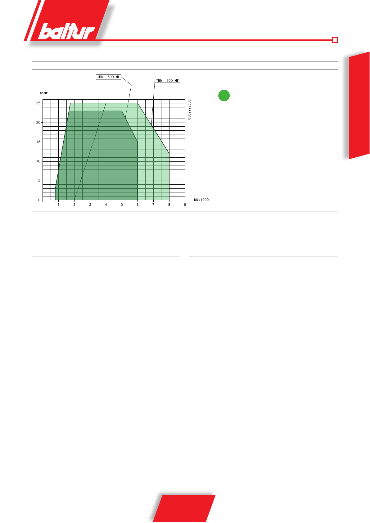
WORKING RANGE
The working ranges are obtained on test
i
boilers compliant with EN676 standards and
are approximate for burner-boiler coupling.
To ensure correct burner operation, the
dimensions of the combustion chamber
must comply with current regulations; if this
is not the case, consult the manufacturers.
- - - Minimum diesel adjustable power for both
models
ENGLISH
DESIGN FEATURES
The burner consists of:
• Ventilating part in light aluminium alloy.
• Centrifugal fan for high performances.
• Intake air conveyor.
• Combustion head complete with stainless steel nozzle.
• Flame inspection glass
• Three-phase electric motor to run fan.
• Air pressure switch to ensure the combustion air presence.
• Gas train complete with control valve, operating and safety
valves, minimum and maximum pressure switches, pressure
control and gas filter.
• Fuel flow rate regulation by means of servomotor controlling gas
valve and flow rate regulator.
• Automatic burner command and control equipment with
microprocessor (electronic cam) in accordance with European
standard EN298 integrated with valve seal control. Display
showing operating sequence and error code in case of shutdown.
• Flame presence control with UV photocell.
• Control panel including on/off and burner off switches, fuel
selector, operation and shut-down warning lights, keypad for
programming electronic cam
• Electric system with protection class IP54.
TECHNICAL FUNCTIONAL FEATURES
• Dual burner, able to operate alternately with natural gas or with
diesel (max viscosity 1.5°E at 20°C).
• EC approval according to European Standard EN 676 for natural
gas and Standard EN 267 for diesel.
• Progressive / modulating two-stage operation for both fuels.
• Electronic command and control equipment Lamtec mod. BT
340, fitted with microprocessor.
• Fuel flow rate / comburent air regulation by means of two
servomotors controlled by the electronic equipment
• Combustion head with partial recirculation of combusted gases
with reduced emissions (class III according to EN 676 for natural
gas, class II according to EN 267 for diesel).
• Hinge opens both ways to permit convenient access to the mixer
without dismantling the burner from the boiler.
• Air minimum and maximum flow rate regulation by means of
electric stepper servomotor with pause closure of shutter to
prevent any heat dispersion to flue.
• Valve seal control functions according to European Standard
EN676 and power regulation functions (read carefully the
operating instructions given in the RAPID GUIDE supplied along
with the burner for further details about the BT 340 equipment
operations).
• Device for the adjustment of auxiliary cooling air to the diesel
nozzle
7 / 28
0006081557_201310
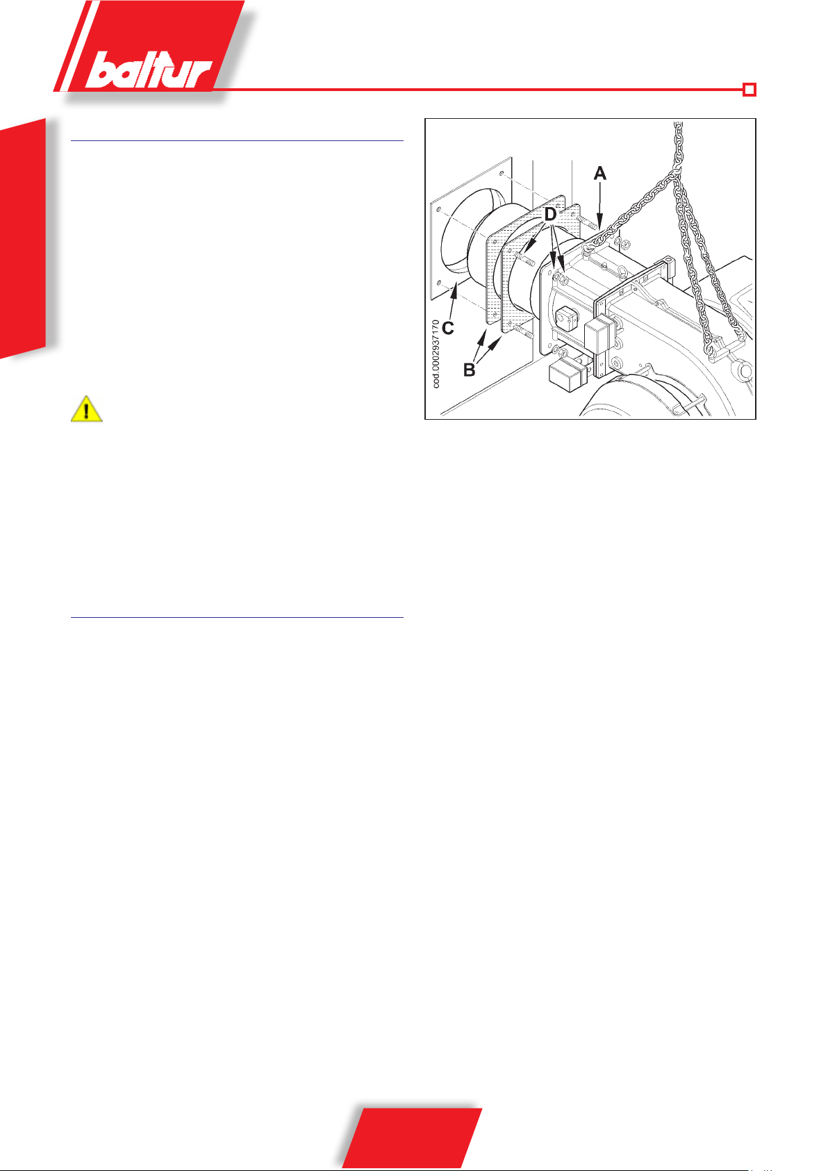
BURNER CONNECTION TO THE BOILER
ASSEMBLING THE HEAD UNIT
Make sure that the combustion head penetrates the furnace by the
amount specified by the boiler manufacturer .
Prior to installing the burner in the boiler, make sure the nozzle is
suitable for the power required, if this is not the case, replace it
following the instructions provided in the diagram стр.15
For the handling of the burner, it is recommended to use a suitable
ENGLISH
hoisting equipment to be anchored to the eyebolts shown in figure
0002937170.
Anchor the burner to the boiler door as follows:
• Place the two insulating seals (B) on the burner connection
flange (A)
• Anchor the flange (A) to the boiler (C) with the stud bolts,
washers and nuts provided (D).
Seal the space between the burner sleeve and the hole on
the refractory material inside the boiler door completely with
suitable material.
ELECTRICAL CONNECTIONS
It is recommended that all connections are performed with electrical
exible wires. Power lines must be outdistanced from the hot parts.
Check that the power line to which the device is connected is powered with voltage values and frequency suitable for the burner. Make
sure that the main line, the relevant switch with fuses (essential)
and the possible limiter are suitable to stand the maximum current
absorbed by the burner.
For more details, see the relevant wiring diagrams for each single
burner.
8 / 28
0006081557_201310
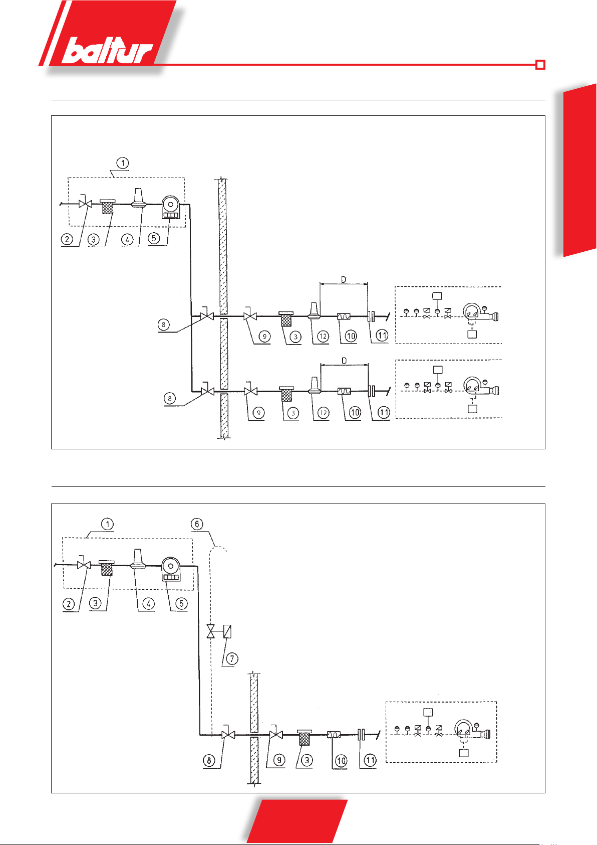
CONNECTION DIAGRAM OF MULTIPLE BURNERS TO THE MEDIUM PRESSURE GAS SUPPLY NETWORK
1 - Reduction and measurement control unit
2 - Shut-off cock
3 - Gas lter
4 - Pressure reducer
5 - Meter
6 - Emergency shut-off cock (installed outside)
7 - Ball cock
8 - Gas lter
9 - Pressure reducer or regulator/stabilizer (according to the case)
10 - Vibration-proof joint
11 - Flange union
D= Distance between gas valves and pressure stabilizer (approx. 1.5 ÷ 2 m)
ENGLISH
CONNECTION DIAGRAM OF ONE BURNER TO THE MEDIUM PRESSURE GAS SUPPLY NETWORK
1 - Reduction and measurement control unit
2 - Shut-off cock
3 - Gas lter
4 - Pressure reducer
5 - Meter
6 - Release into the atmosphere with ame trap wire gauze
7 - Possible automatic overow valve
(it must discharge outside in a suitable place)
8 - Emergency shut-off cock (installed outside)
9 - Ball cock
10 - Vibration-proof joint
11 - Flange union
N° 8530/1
9 / 28
0006081557_201310
N° 8531/1

FUEL (DIESEL) SUPPLY SYSTEM
The burner pump must receive the fuel from a suitable supply circuit
featuring an auxiliary pump which may feature a pressure regulator
adjustable from 0.5 to 3 bar. In this case, the fuel supply pressure to
the burner pump (0.5 ÷ 3 bar) must not change both with burner off
and with working burner at the maximum fuel output required by the
boiler. In normal cases, this circuit can be realized without pressure
regulator, abiding to the following diagram. The supply circuit must
ENGLISH
be realized according to diagram 8666/3.
The pipe dimensioning must be carried out according to the pipe
length and the ow rate of the installed pump. Our instructions ensure
a good operation of the product.
The anti-pollution prescriptions, as well as the provisions set forth
by the local authorities, refer to the specic publications.
DUAL FUEL BURNER IGNITION INFORMATION:
We recommend performing the first ignition with liquid fuel because,
in this case, the output is conditioned by the nozzle that is used,
whereas the output of natural gas can be varied as required by
regulating the flow rate regulator.
HYDRAULIC DRAWING OF SUPPLY FOR ONE OR MORE DIESEL TWO-STAGE OR
MODULATING BURNERS WITH MAXIMUM NOMINAL VISCOSITY (5°E AT 50°C)
The fuel recovery tanks (diameter ~ 150 mm - height ~ 400 mm)
must be installed as close as possible to the burner at least 0.5
m above the burner pump.
8666/3
1 - Main tank
2 - Filter
3 - Circulation pump
4 - Water and system outlet
6 - Fuel recovery tank and degasser
7 - Non-return valve
8 - By-pass (normally closed)
10 / 28
0006081557_201310

ASSEMBLING THE GAS TRAIN
The EN 676 approved gas train is sold separately from the burner .
The gas train can be assembled in different ways: A and B. Choose
the most rational position for the set-up of the boiler room and the
position in which the gas pipe arrives.
HINGE UNIT ASSEMBL Y
The burner hinge can be opened both ways, it is therefore possible
to reverse the opening side of the ventilating body. As a standard,
the burner is supplied with the hinge installed on the right side .
To enable the maximum opening and so facilitate maintenance
operations, it is recommended to install the hinge on the side of
the burner opposite to the position where the gas train is installed.
In case it is necessary to install the hinge on the left side, proceed
as follows:
• After installing the burner on the boiler, loosen the N fastening
screws and open the ventilating body to the amount needed for
the removal of the E centring pin (0002937220).
• Close the burner again by re-tightening the N screws and remove
the two F hinges and the G pin.
• Then, remove the 3 N screws and the relevant washers on
the left side of the flange and refit them on the right side T in
correspondence with the holes left free after removal of the
hinges.
• Fit the hinge unit on the burner left side (0002937230).
Initially place the F hinges without tightening the 4 H screws.
First make sure that the S abutting surfaces of the two hinges
are perfectly in contact with the corresponding volute sides.
Prior to this, tighten the 2 M nuts and the relevant washers.
Do not tighten the nuts too deeply, as this may make hinge
rotation difficult. Carry out the final tightening of the H screws
to complete the operation.
ENGLISH
• Open the ventilating body again to make sure that the hinge
unit rotates correctly and re-fit the centring pin on the side of
the fan flange opposite to the hinge side in order to facilitate
closing again of the burner.
Each time the burner has to be opened, first disconnect the
connectors to the gas butterfly servomotor, to the diesel
pressure regulator, to the gas solenoid valves and to the
diesel circuit.
0006081557_201310
11 / 28
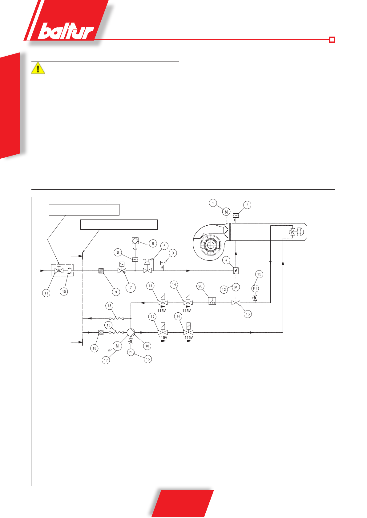
DIAGRAM ILLUSTRATING GAS TRAIN PRINCIPLE
Install a manual on/off valve upstream of the gas valve and
a vibration-proof joint according to the layout shown in the
diagram illustrating the principle.
To ensure optimal functioning of the pressure control, it should
be applied to the horizontal pipe after the filter. The gas pressure
regulator must be adjusted while operating at the maximum flow
rate actually used by the burner. The outgoing pressure must
be adjusted to a value slightly below the maximum possible
ENGLISH
value (the value obtained by screwing in the adjustment screw
almost completely); in this case, the outgoing regulator pressure
increases as the adjustment screw is tightened, and decreases as
it is slackened.
DIAGRAM ILLUSTRATING DUAL FUEL BURNERS SERIES TBML 600 / 800
TO BE SUPPLIED BY INSTALLER
LIMITS ON BALTUR SUPPLY
DIESEL RETURN
DISELE INTAKE
1 Air regulation servomotor
2 Air pressure switch
3 Maximum gas pressure switch
4 Gas supply modulating control butterfly valve
5 Operating gas valve with pressure regulator
6 Valve seal control device (integrated in the equipment)
7 Safety gas valve
8 Minimum pressure switch and gas leak control.
9 Gas filter
10 Vibration-proof joint (not included in supply)
11 Ball cock (not included in supply)
0002901660
12 Gas / diesel regulator servomotor
13 Diesel return flow rate regulator
14 Diesel solenoid valve (NC)
15 Pressure gauge 0÷40 bar
16 Burner pump (25 bar)
17 Pump motor
18 Hose
19 Diesel filter
20 Maximum diesel pressure switch
12 / 28
0006081557_201310

DIESEL IGNITION AND REGULATION
• Turn the switch on the control panel to the “O” position (open).
• Turn the switch “fuel change-over” to the “OIL” position.
• Close the auxiliary air to the head unscrewing the pawl (A)
and pulling the rod (B) down to its end of stroke. Retighten the
pawl (A).
• Close the gate and open the shut-off elements.
• Check that there is water in the boiler and that the gates on the
system are open.
• Make sure that the products of combustion can be released
freely (boiler and chimney dampers open).
• Check that the voltage of the electric line the equipment must
be connected to, complies with the manufacturer prescriptions,
and that the motor electric connections are properly set for the
available voltage. Also check that all electric connections made
on-site are performed correctly as shown in our wiring diagram.
• Start the fuel supply auxiliary circuit and check for its correct
operation, then set pressure to nearly 0,5÷3 bar if such circuit
features a pressure regulator.
• Remove the vacuum gauge connection plug from the pump and
open the gate on the fuel pipe. Wait for the fuel to flow out of the
hole without air bubbles and close the gate. In case no supply
circuit under pressure is available, fill the pump by pouring fuel
into the supply hose.
• Fit a pressure gauge (full scale approx. 4 bar) to the pump
vacuum gauge connection point to check the pressure value at
which the fuel reaches burner pump. Fuel pressure must remain
within 0,5÷3 bar also when the burner is off.
• Open the gates placed on the diesel pipes.
• Power the electric line to which the burner is connected. Manually
press the specific remote control switches to check that the fan
and pump motors turn in the correct direction. If necessary,
change the position of the two cables of the main line to reverse
the rotation direction.
• Start the burner pump by manually pressing the relevant remote
control switch until the pump pressure gauge detects a slight
pressure. A slight pressure in the circuit indicates that it has
been filled up.
• Connect (pos. I) the switch (1) on the control panel to power
the equipment and close the thermostat line turning the selector
(2) in the "closed" position. If thermostats or pressure switches
(safety and boiler) are closed as well, the operating cycle will
start. The equipment turns on. For the regulation of the burner,
see la “RAPID GUIDE TO PROGRAMMING” and the specific
instruction manual for the “BT 340” electronic cam .
• Check that the flame detector is triggered.
• FLAME SENSOR
If the flame is detected by the UV photocell remember what
specified below. A slight amount of grease will strongly
compromise the passage of the light radiations, preventing the
internal sensitive element from receiving the quantity of radiations
required for proper operation. If the bulb is fouled, it must be
properly cleaned. Even the simple contact with your fingers can
leave a slight amount of grease that is enough to compromise the
A
Rod position with "CLOSED" auxiliary air to the nozzle
(DIESEL operating mode)
2
1
B
TBML600800ME02
ENGLISH
synoptic_TBML 800 ME
13 / 28
0006081557_201310

operation of the photocell. The photocell does not "detect" daylight
or the light from a common lamp. Its sensitivity can be tested
using a flame (lighter, candle). To ensure a proper operation,
the cell voltage value must be sufficiently stable and not go
below the minimum value required for the specific equipment.
The check is performed between the terminals of the electric
panel as shown in the wiring diagram.
• When the burner is working at its "minimum" output, adjust the air
and diesel in the proper quantities to ensure a good combustion.
ENGLISH
• After adjusting the air for the operation at the "minimum"
output, increase the power and proceed to define the
operating curve as described in the equipment manual. It
is recommended to check combustion using the specific
instrument at all intermediate points on the modulation curve.
The maximum output is obtained with a return pressure of
approx. 17 - 18 bar at a pump pressure of 25 bar (0002922840
стр. 15). It is recommended not to exceed the value of 13 %
of CO
in the smoke.
2
14 / 28
0006081557_201310
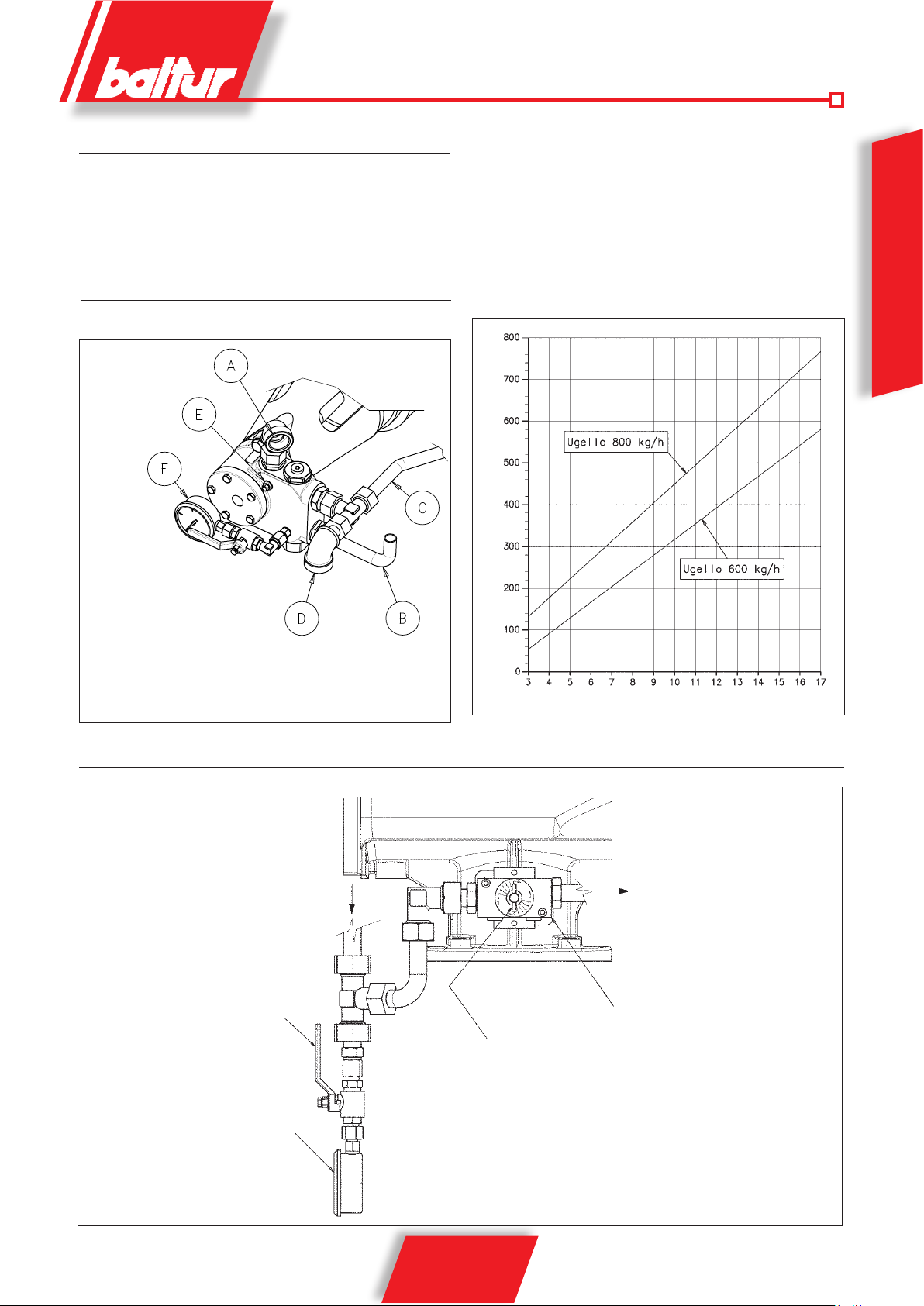
FLUIDICS NOZZLE WITHOUT PIN
For diesel operation, use nozzles model FLUIDICS N2 45° without
pin for 600 kg/h or 800 kg/h, depending in the maximum regulated
thermal rate.
Diagram 0002922840 represents the curves showing the values
of the fuel flow rate delivered by the two nozzles depending on the
PUMP CONNECTION DIAGRAM HP MODEL VBH
return pressure. The curves were obtained by considering a diesel
pump regulating pressure of 25 bar.
The return pressure value is to be measured on the pressure gauge
with scale 0-40 bar of diagram 0002901670.
ENGLISH
0002922840
N° 0002901681
DIESEL FLOW RATE (kg/h)
A Intake 1"¼
B Diesel delivery to burner
C Diesel return from pump
D 1"¼ connection for diesel return
E Vacuum gauge connection ( ⅛ )
F Pressure gauge 0 ÷ 30 bar
FLOW RATE REGULATOR CONNECTION DIAGRAM
Diesel inlet from nozzle return
Cock
NOZZLE RETURN PRESSURE (bar)
0002901670
Diesel outlet on
pump return
Diesel flow rate regulator
Pressure gauge with scale 0-40
bar for measuring the nozzle return
pressure
Servomotor rotation indicator
position 6: flow rate regulator closed, maximum flow rate delivered by the nozzle.
position 0: flow rate regulator completely open, minimum flow rate delivered by
the nozzle.
15 / 28
0006081557_201310

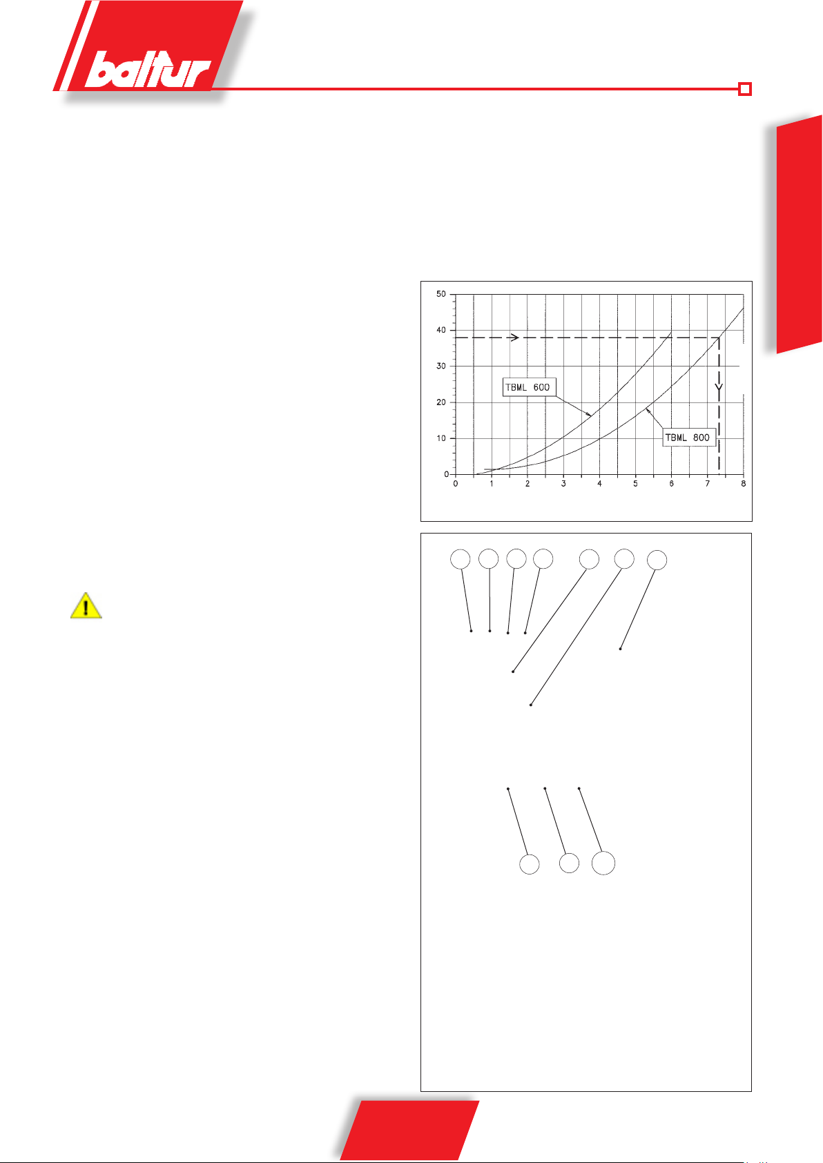
GAS (METAL GAS) IGNITION
AND REGULATION
A
B
• Turn the switch on the control panel to the “O” position (open).
• Turn the switch “fuel change-over” to the “GAS” position.
• Open the auxiliary air to the head unscrewing the pawl (A)
and pulling the rod (B) down to its end of stroke. Retighten the
pawl (A)
ENGLISH
• Close the gate and open the shut-off elements.
• Check that there is water in the boiler and that the gates on
the system are open.
• Make absolutely sure that the products of combustion can
be released freely (boiler and chimney gates open).
• Check that the voltage of the electrical line to which the
equipment has to be connected is appropriate for the burner and
that the electrical wiring (engine or main line) are appropriate for
the available voltage. Check that all electrical connections made
on-site are performed correctly as shown in our wiring diagram.
• It is essential to bleed air out of the pipes, if this has not already
been done when connecting the burner to the gas pipe, taking
all necessary precautions and leaving all doors and windows
open. Open the union on the pipe near the burner and then open
the gas on/off cocks a little way. Wait until you smell gas, close
the cock. Wait long enough for the gas in the room to disperse,
depending on local conditions, then connect the burner to the
gas pipe again.
• Apply a pressure gauge of appropriate scale (if the amount
of pressure to be used permits, it is preferable to use a water
column instrument; do not use instruments with indicator hands
for low pressures) to the pressure intake on the gas pressure
switch.
• With burner switch to “O” and main switch turned on, manually
close the remote control and check that the motor revolves in
the correct direction. If necessary, change the position of the
two cables in the line that feeds the motor in order to reverse
the direction of revolution.
• Connect (pos. I) the switch (1) on the control panel to power
the equipment and close the thermostat line turning the selector
(2) in the "closed" position. If thermostats or pressure switches
(safety and boiler) are closed as well, the operating cycle will
start. The equipment turns on. For the regulation of the burner,
see “RAPID GUIDE TO PROGRAMMING” and the specific
instruction manual for the “BT 340” electronic cam .
• Check that the flame detector is triggered (UV cell) with the
burner on, remove it from its housing in the burner and check
that it shuts down.
• Check the efficiency of the thermostats or boiler pressure
switches (they should shut down the burner when triggered).
• FLAME SENSOR
If the flame is detected by the UV photocell remember what
specified below. A slight amount of grease will strongly
compromise the passage of the light radiations, preventing the
internal sensitive element from receiving the quantity of radiations
required for proper operation. If the bulb is fouled, it must be
TBML600800ME05
Rod position with "OPEN" auxiliary air to the nozzle
(GAS operating mode)
G
press TBML ME.psd
16 / 28
0006081557_201310
properly cleaned. Even the simple contact with your fingers can
leave a slight amount of grease that is enough to compromise the
operation of the photocell. The photocell does not "detect" daylight
or the light from a common lamp. Its sensitivity can be tested
using a flame (lighter, candle). To ensure a proper operation,
the cell voltage value must be sufficiently stable and not go
below the minimum value required for the specific equipment.
The check is performed between the terminals of the electric
panel as shown in the wiring diagram.
• When the burner is working at its "minimum" output, adjust the
air and gas in the proper quantities to ensure a good combustion.
• After adjusting the air for the operation at the "minimum" output,
increase the power and proceed to define the operating curve as
described in the equipment manual. It is recommended to check
combustion using the specific instrument at all intermediate
points on the modulation curve.
• Once the regulation of air and gas is complete, check the
amount of gas actually delivered by reading the meter. Do not
permit the burner to operate if the combusted thermal flow rate
exceeds the maximum one permitted for the boiler, to prevent
it from being damaged. Upon defining the modulation curve, it
is possible to have an approximate estimate of the thermal flow
rate delivered at the intermediate points be measuring the gas
pressure in the combustion head. Connect a pressure gauge
with scale appropriate to the port (G) (see picture) and measure
the gas pressure. From diagram (0002922850 стр. 17) obtain
the thermal flow rate delivered, depending on the value of the
pressure measured without the back pressure in the furnace.
This method permits only an approximate estimate of
the combusted thermal flow rate delivered, for a precise
measuring, refer to gas meter.
Example:
• Burner TBML 800
• Pressure measured on port G: Ptc=48 mbar
• Back pressure measured in the furnace: Pcc=10 mbar
• Head pressure value without the back pressure in the furnace:
P=48-10=38 mbar
• From the diagram, in correspondence of pressure P=38 mbar, a
combusted thermal flow rate of about 7300 kW can be inferred.
Head gas net pressure (mbar)
Thermal flow rate (kW x 1000)
7
5
4
8 9
6
3
ENGLISH
0002922850
1 Main switch ON - OFF
2 Thermostatic line switch
3 BT 340 Display
4 Equipment shut-down warning light
5 Voltage warning light
6 Fan shut-down, if supplied
7 Gas warning light
8 Diesel warning light
9 Pump motor lock
10 Fuel selector (gas / diesel)
17 / 28
0006081557_201310
10
2
1
synoptic_TBML 800 ME
AIR PRESSURE SWITCH
FUNCTIONAL DESCRIPTION
The air pressure switch is used to lock the equipment if air pressure
is not at the expected value. The pressure switch must be set to
trigger when the air pressure in the burner does not reach the
sufficient value.
To ensure the air pressure switch correct operation, with burner at
the minimum output, increase the adjustment value until reaching
the triggering value which must be followed by the immediate burner
ENGLISH
shut-down. Press the release button to resume the burner operation,
and set the pressure switch to a sufficient value to detect the air
pressure during the first phase of pre-ventilation.
GAS PRESSURE SWITCH
FUNCTIONAL DESCRIPTION
The gas pressure switches (minimum and maximum) prevent
the burner from operating when gas pressure is not between the
expected range. The specific function of the pressure switches
clearly reveals that the pressure switch for controlling minimum
pressure uses the NO (normally open) contact which closes when
the pressure switch detects a pressure value above the value it is set
to, while the pressure switch for controlling maximum pressure uses
the NC (normally closed) contact that is closed when the pressure
switch detects a pressure lower than the value it is set to. The
minimum and maximum gas pressure switches must be set when
testing the burner, on the basis of the pressure measured in each
case. The pressure switches are connected in a way in which the
triggering (i.e. circuit opening) of the pressure switch controlling the
maximum pressure produces the immediate locking of the burner;
whereas, when the pressure switch controlling the minimum pressure
is triggered, the burner stops and remains in the stand-by status until
the pressure within the values needed for the operation is restored.
After that, the burner re-starts in an autonomous way following the
ignition sequence.
Regulation prior to burner ignition: regulate the pressure switch for
minimum pressure at the minimum value of the scale, regulate the
pressure switch for the maximum value at the maximum value of
the scale. Regulation after the burner regulation : With the burner
at the maximum delivery, regulate the pressure switch for minimum
pressure by increasing the regulation value until the burner shuts
down, read the value on the regulation ferrule and set it to a value
diminished by 5 mbar. With the burner at the minimum delivery,
regulate the pressure switch for maximum pressure, diminishing the
regulation value until the NC (normally closed) contact opens. Read
the value on the regulation ferrule and set it to a value increased
by 5 mbar.
in case only one pressure switch is installed on the gas trainit
must be a pressure switch for minimum pressure.
press TBML ME.psd
18 / 28
0006081557_201310
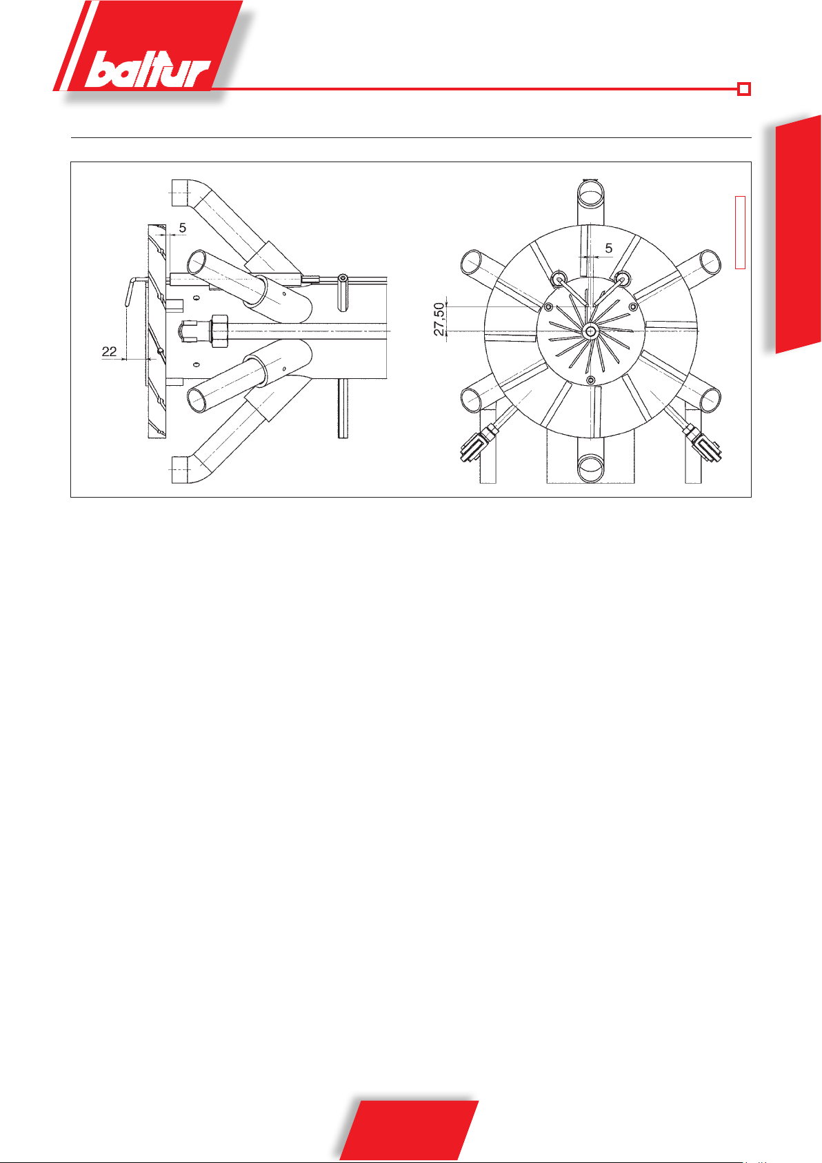
DIAGRAM ILLUSTRATING REGULATION OF COMBUSTION HEAD AND DISTANCE OF ELECTRODE DISK
N° 0002937182
ENGLISH
19 / 28
0006081557_201310
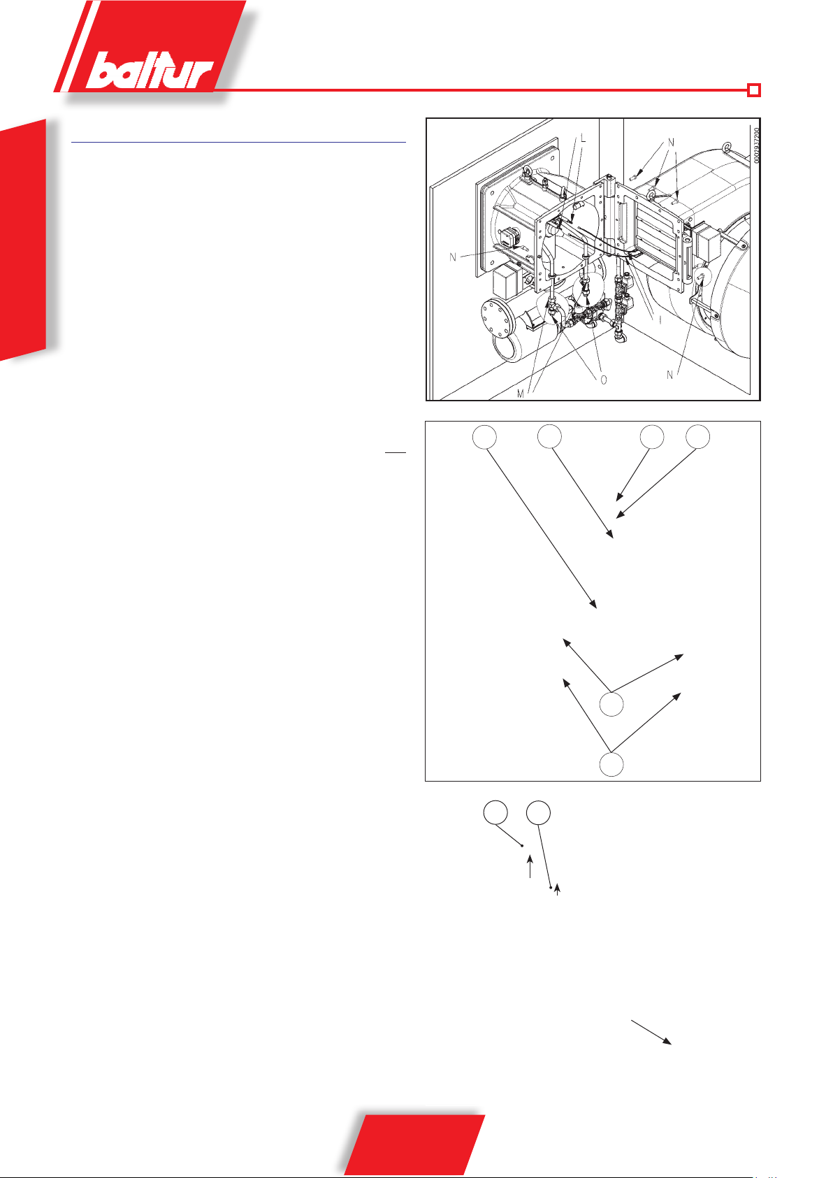
MAINTENANCE
The burner does not require any particular maintenance, it is
recommended at least to carry out the following operations at the
end of the heating season:
• Clean air dampers, the air pressure switch with pressure port
and the relevant pipe.
• Clean the photocell.
• If necessary, have the burner and the chimney cleaned by
ENGLISH
specialized personnel (stove repairer); a clean burner is more
efficient, lasts longer and is quieter.
• Periodically check that the gas filter is clean for gas burners.
• In order to clean the combustion head, its components
must be disassembled. Be careful during the reassembly
operations to exactly centre the gas diffuser with
regard to the electrodes, making sure that they are not
earthed, which would result in the locking of the burner.
After regulating the two electrodes as described at diagram
0002937182. Make sure that the ignition spark occurs only
between the two electrode ends.
• Analyse combustion gases and check emissions values.
• Check that all components of the combustion head are in good
condition, have not been deformed by high temperatures and
are free from impurities or deposits deriving from the installation
environment or from poor combustion. If it is necessary to clean
the combustion head, take out its components according to the
procedure described below:
- remove the UV photocell
- Disconnect the connectors of gas and diesel solenoid valves,
the gas servomotor and of the pressure regulator.
- unscrew the anchoring screws (N), and open the ventilating
body;
- pull out the ignition cables (I) from their ignition electrode
terminals (L);
- Unscrew the caps (O), on one of which the pressure gauge
indicating the pressure in the return circuit is installed, to
enable the draining of the residual diesel still present in
the atomization unit. Disconnect the unit connection pipes,
unscrewing the nuts (M) of the "T" -shaped unions.
- Loosen the nut (A) and the pawl (B), turn the rod (C) to
unscrew it from the piston (D), then remove it completely
from the burner body.
- Unscrew the screw (R) and the screw (S) from the lung (P);
- pull out the entire mixer unit in the direction shown by the
arrow. When you have finished maintenance work, proceed
to reassemble the combustion head, following the same
procedure in reverse, after checking the correct position of
the ignition electrodes (0002937182стр. 19).
B
C
D
A
TBML600800ME03
M
O
R
S
TBML600800ME04
20 / 28
0006081557_201310

BURNER USE
Burner's operation is fully automatic; it starts up by enabling the
master and the control panel switch. Correct burner operation is
regulated by command and control devices, as described in the
chapter "Operation description". The "lock" position is a safety
position that the burner automatically assumes when a burner
or system component is not working properly. It is recommended
before starting again the burner "by releasing it" to check for faults
in the heating plant before restarting the burner. The burner may
stay in the lock position without any time limits. To release it, press
the red flashing button on the display of the BT 340 equipment
("ENTER" button).
Locking may also be caused by temporary faults; in these cases if it
is released, the burner will start up again in a regular way. If locking
continue to occur (3-4 times), do not continue with the operation
and, after having checked that the fuel arrives to the burner, ask the
intervention of the after-sales service in your area.
avvio.psd
ENGLISH
21 / 28
0006081557_201310
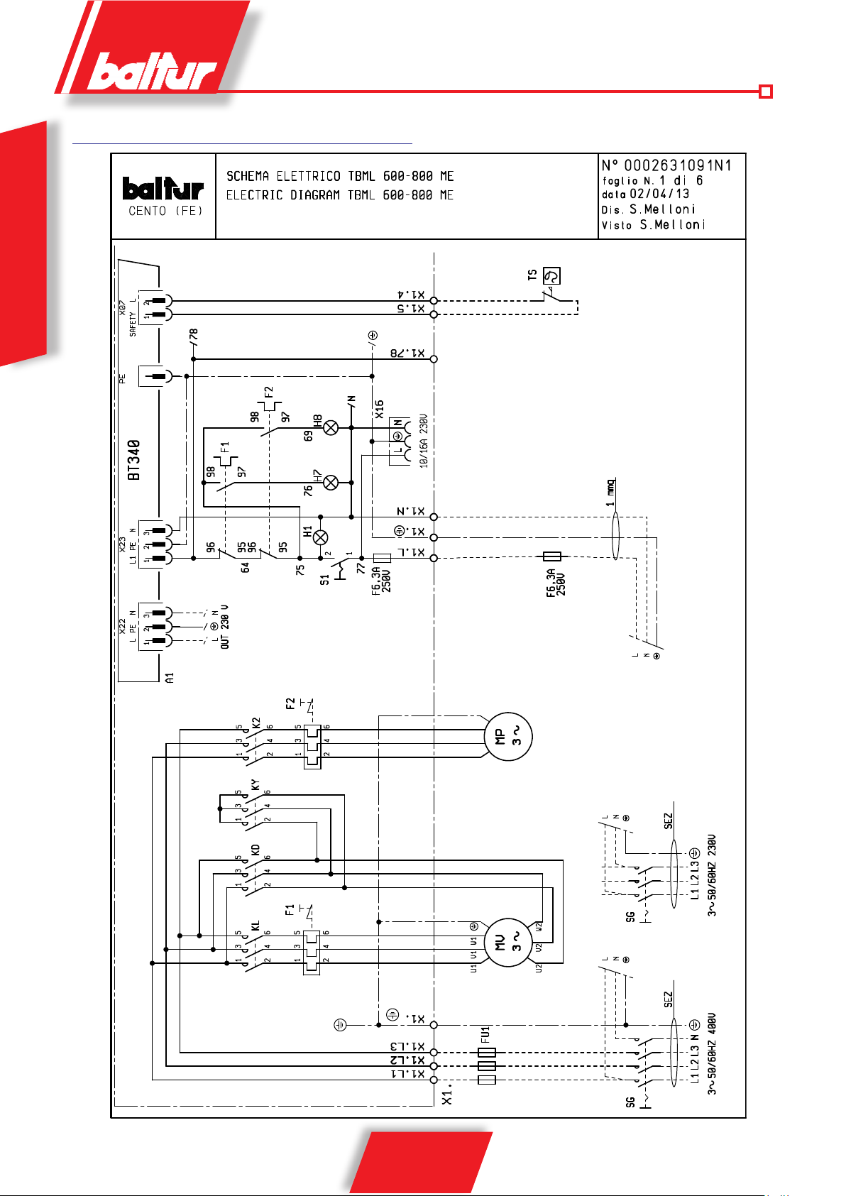
WIRING DIAGRAM
ENGLISH
22 / 28
0006081557_201310
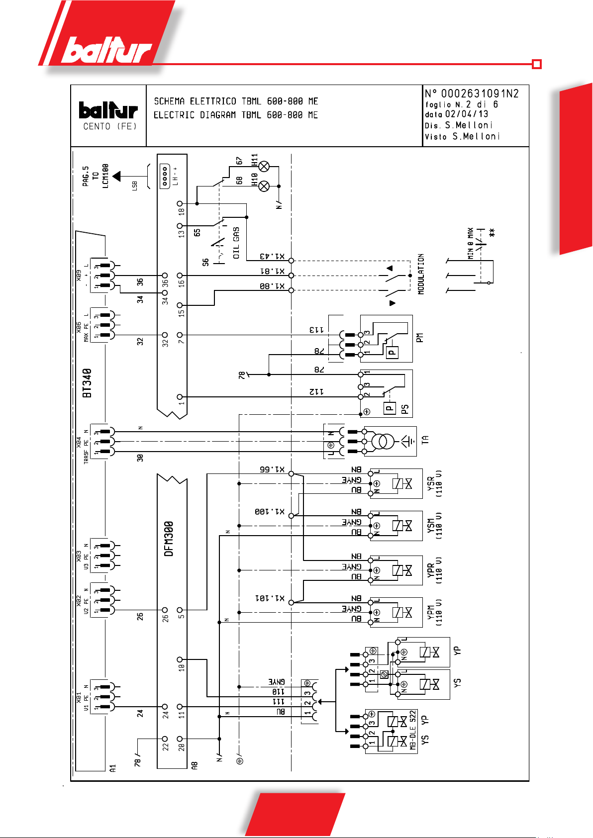
** ONLY FOR REGULATION
ENGLISH
23 / 28
0006081557_201310
ENGLISH
24 / 28
0006081557_201310
ENGLISH
25 / 28
0006081557_201310
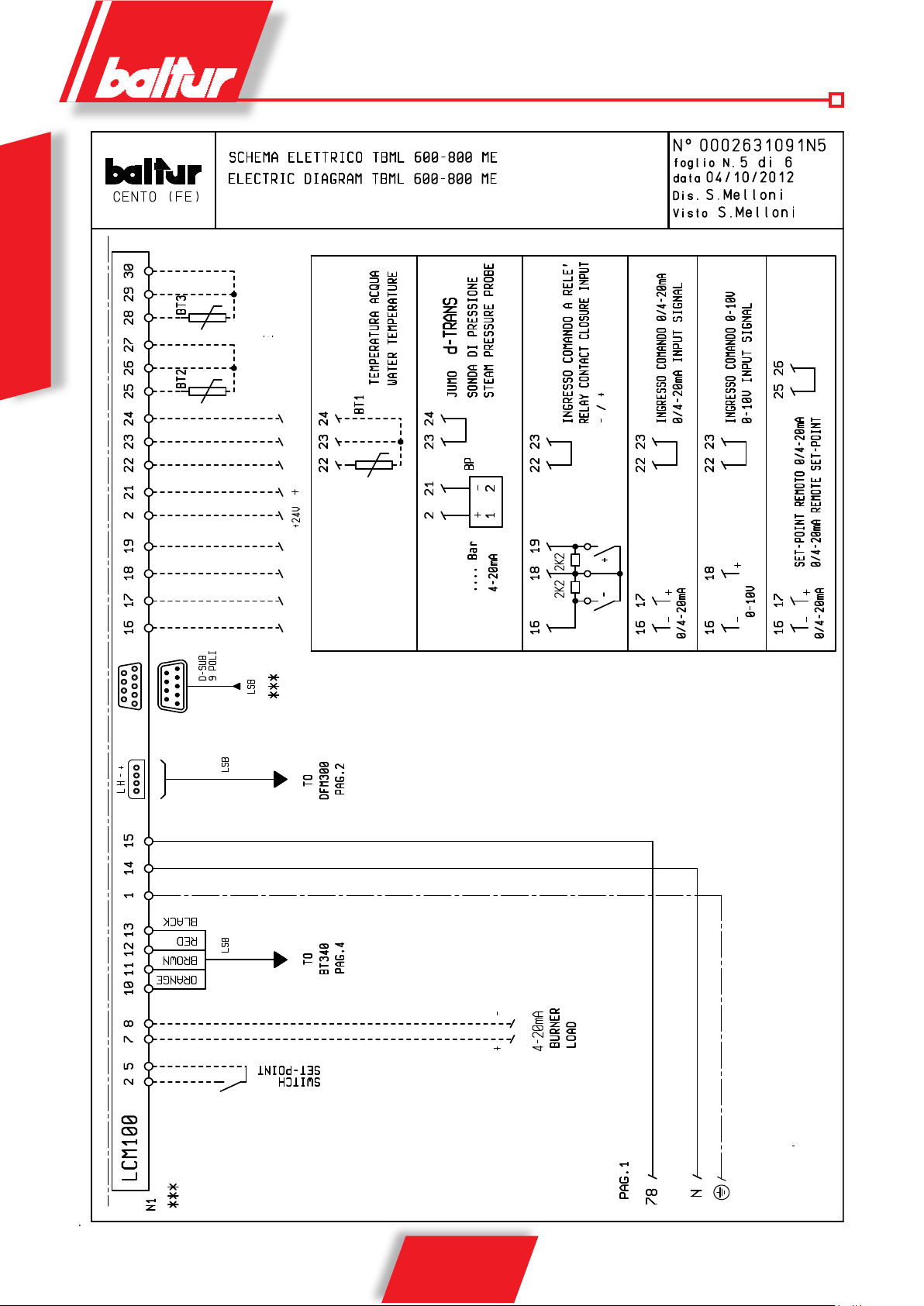
ENGLISH
SMOKE
EXTERNAL
TEMPERATURE
TEMPERATURE
SENSOR
SENSOR
WATER TEMPERATURE
SENSOR
PRESSURE PROBE
CUT-OUT CONTROL INLET
CONTROL INLET 0/4 - 20 mA
26 / 28
0006081557_201310
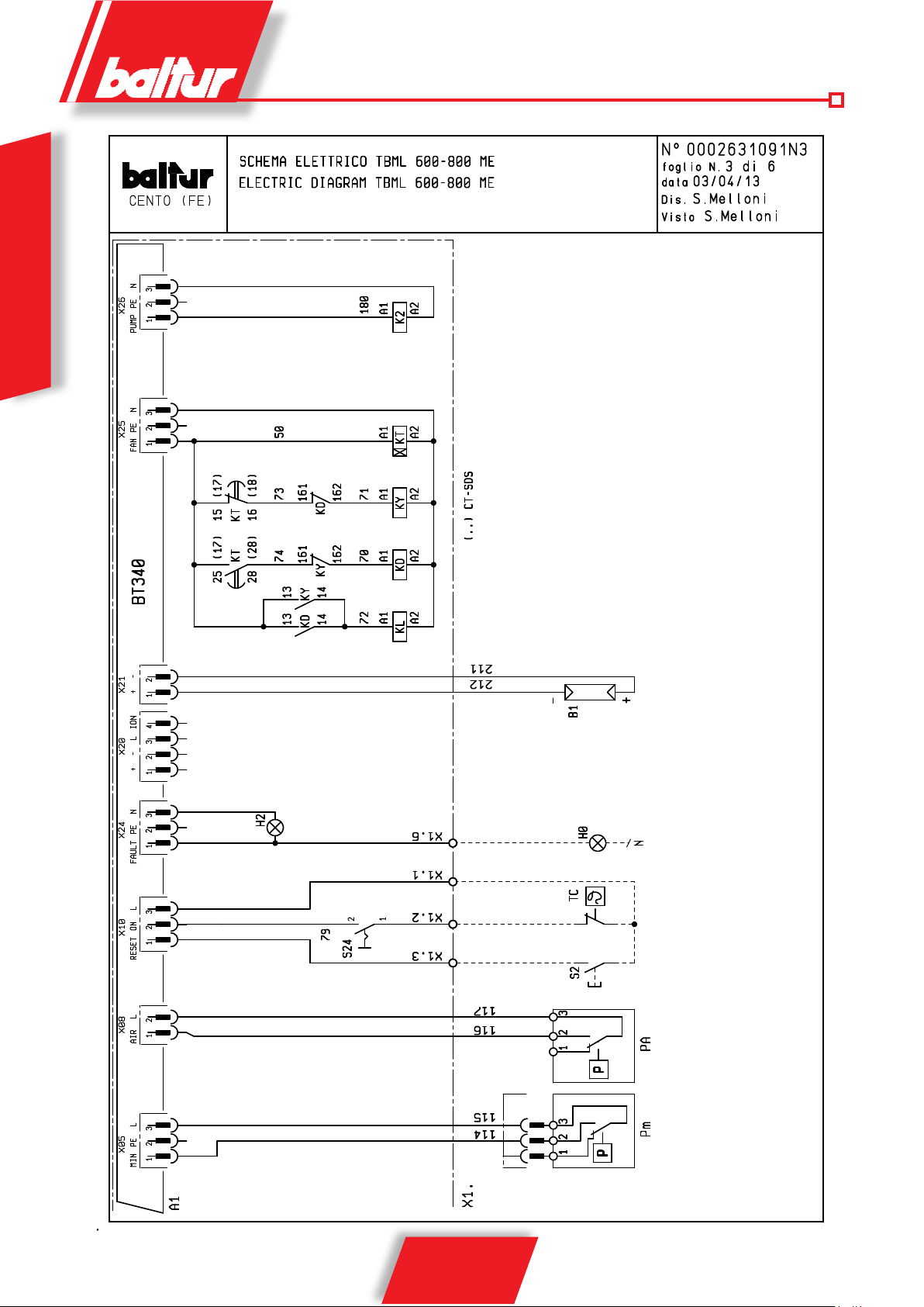
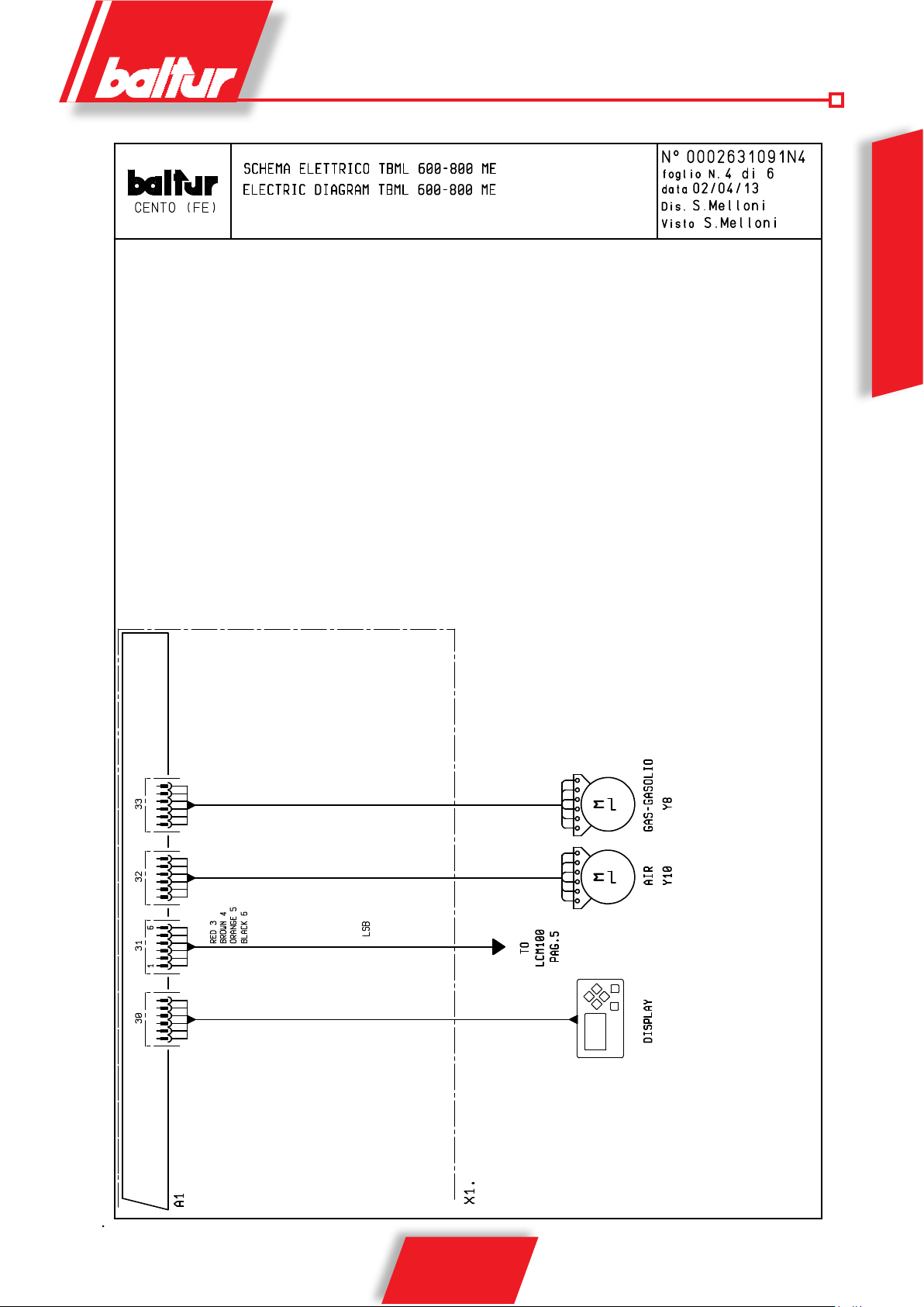
*** POSSIBLE
A1 EQUIPMENT
A8 EQUIPMENT FOR TWO FUELS
B1 UV PHOTOCELL
F1 THERMAL CUT-OUT
F2 PUMP THERMAL CUT-OUT
FU1 FUSES
H0 EXTERNAL SHUT-DOWN WARNING LIGHT
H1 OPERATION WARNING LIGHT
H10 GAS OPERATION WARNING LIGHT
H11 GAS WARNING LIGHT
H2 A1 SHUT-DOWN WARNING LIGHT
H7 FAN MOTOR SHUT-DOWN WARNING LIGHT
H8 PUMP MOTOR THERMAL SHUT-DOWN WARNING LIGHT
K2 PUMP MOTOR CONTACTOR
KL LINE CONTACTOR
KD TRIANGLE CONTACTOR
KY STAR CONTACTOR
KT TIMER
MP PUMP MOTOR
MV FAN MOTOR
N1 ELECTRONIC REGULATOR
P M MAXIMUM PRESSURE SWITCH
PA AIR PRESSURE SWITCH
Pm MINIMUM PRESSURE SWITCH
PS SAFETY PRESSURE SWITCH
S1 START/STOP SWITCH
S2 RELEASE BUTTON
S6 GAS-OIL SELECTOR
S24 SWITCH ON/OFF
SG MAIN SWITCH
TA IGNITION TRANSFORMER
TC BOILER THERMOSTAT
TS SAFETY THERMOSTAT
X1 BURNER TERMINAL BOARD
X16 SERVICE PORT
Y8 GAS / DIESEL SERVOMOTOR
Y10 AIR SERVOMOTOR
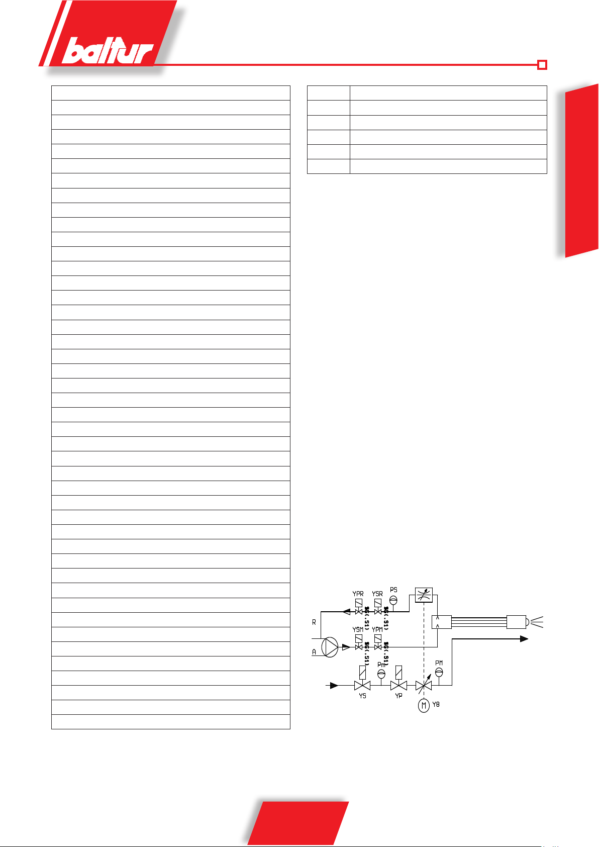
YP MAIN SOLENOID VALVE
YPM MAIN DELIVERY SOLENOID VALVE
YPR MAIN RETURN SOLENOID VALVE
YS SAFETY SOLENOID VALVE
YSM DELIVERY SAFETY SOLENOID VALVE
YSR RETURN SAFETY SOLENOID VALVE
DIN / IEC
GNYE GREEN/YELLOW
BU BLUE
BN BRUNO
BK* BLACK
BK* BLACK CONDUCTOR WITH OVERPRINT
ENGLISH
SPRAY NOZZLE UNIT
GAS TRAIN
27 / 28
0006081557_201310

ENGLISH
28 / 28
0006081557_201310
 Loading...