

Page 1

BRUCIATORE MISTO GAS / GASOLIO
MIXED GAS/DIESEL BURNER
ITALIANO
Manuale istruzioni per l'installazione,
l'uso e la manutenzione
Installation, use and maintenance
instruction manual
IT
EN
TBML 50MC
ISTRUZIONI ORIGINALI (IT)
ORIGINAL INSTRUCTIONS (IT)
0006160003_201510
Page 2

Page 3

ITALIANO
SOMMARIO
ITALIANO
Avvertenze per l'uso in condizioni di sicurezza ................................................................................................................................pag 4
Caratteristiche tecniche .................................................................................................................................................................... pag 7
Materiale a corredo ....................................................................................................................................................................pag 8
Targa identicazione bruciatore..................................................................................................................................................pag 8
Dati registrazione prima accensione .......................................................................................................................................... pag 8
Campo di lavoro ......................................................................................................................................................................... pag 9
Dimensioni di ingombro ............................................................................................................................................................ pag 10
Descrizione componenti ........................................................................................................................................................... pag 11
Quadro elettrico ........................................................................................................................................................................ pag 11
Applicazione del bruciatore alla caldaia .........................................................................................................................................pag 12
Linea di alimentazione gas ....................................................................................................................................................... pag 13
Schema di principio bruciatori a gas ........................................................................................................................................pag 13
Schemi dimensionamento tubazione .......................................................................................................................................pag 14
Collegamenti elettrici ...................................................................................................................................................................... pag 15
Linea di alimentazione gasolio ................................................................................................................................................. pag 17
Pompa ausiliaria ....................................................................................................................................................................... pag 17
Descrizione del funzionamento con combustibile liquido ............................................................................................................... pag 19
Primo riempimento tubazione ......................................................................................................................................................... pag 20
Accensione e regolazione combustibile liquido .............................................................................................................................. pag 21
Particolari pompa ............................................................................................................................................................................pag 23
Descrizione del funzionamento con combustibile gassoso ............................................................................................................ pag 24
Descrizione del funzionamento della modulazione .................................................................................................................. pag 24
Accensione e regolazione gas metano ...........................................................................................................................................pag 25
Fotocellula UV .......................................................................................................................................................................... pag 26
Controlli .................................................................................................................................................................................... pag 27
Regolazione aria sulla testa di combustione ............................................................................................................................ pag 27
Schema di regolazione distanza disco elettrodi ....................................................................................................................... pag 28
Apparecchiatura di comando e controllo LME 73... ........................................................................................................................ pag 29
Apparecchiatura di comando e controllo LME... ............................................................................................................................. pag 31
Regolazione camme servomotore SQN72.6E5A20BT ...................................................................................................................pag 33
Precisazioni sull'uso del propano ...................................................................................................................................................pag 34
Schema di principio per riduzione pressione G.P.L. a due stadi per bruciatore oppure caldaia ..............................................pag 35
Manutenzione ................................................................................................................................................................................. pag 36
tempi di manutenzione ............................................................................................................................................................. pag 37
tabella portata ugelli .......................................................................................................................................................................pag 38
Istruzioni per l'accertamento delle cause di irregolarità nel funzionamento e la loro eliminazione.................................................pag 39
Schemi elettrici ............................................................................................................................................................................... pag 42
1 / 44
0006160003_201510
Page 4

DICHIARAZIONE DI CONFORMITÀ
CE0085:
DVGW CERT GmbH, Josef-Wirmer Strasse 1-3-53123 Bonn (D)
Dichiariamo che i nostri bruciatori ad aria sofata di combustibili gassosi e misti, serie:
BPM...; BGN…; BTG…; TBML...; Comist…; GI…; GI…Mist; Minicomist…; Sparkgas...; TBG..; IB..; TBR...
(Variante: … LX, per basse emissioni NOx; -V per inverter, FGR per ricircolazione esterna fumi)
rispettano i requisiti minimi imposti dalle Direttive e Regolamenti europei:
• 2009/142/CE - (UE) 2016/426 (D.A.G.) (R.A.G.)
• 2014/30/CE (C.E.M.)
• 2014/35/CE (D.B.T.)
• 2006/42/CE (D.M.)
e sono conformi alle Norme Europee:
• prEN 676:2008 (gas e misti, lato gas)
• prEN 267:2008 (misti, lato gasolio)
• EN 60335-1 (2012-01) + EC (2014-01).
• EN 60335-2-102
• EN 60204-1
Cento, 15 Marzo 2018
Inizio validità: 21/04/2018
Scadenza: 21/04/2019
Amministratore Delegato
Dr. Riccardo Fava
Direttore Ricerca & Sviluppo
Ing. Paolo Bolognin
1 / 1
Page 5

ITALIANO
AVVERTENZE PER L'USO IN CONDIZIONI
DI SICUREZZA
SCOPO DEL MANUALE
Il manuale si propone di contribuire all'utilizzo sicuro del prodotto
a cui fa riferimento, mediante l'indicazione di quei comportamenti
necessari prevedendo di evitare alterazioni delle caratteristiche
di sicurezza derivanti da eventuali installazioni non corrette, usi
erronei, impropri o irragionevoli.
E’ esclusa qualsiasi responsabilità contrattuale ed extracontrat-
tuale del costruttore per i danni causati da errori nell’installazione
e nell’uso, e comunque da inosservanza delle istruzioni date dal
costruttore stesso.
• Le macchine prodotte hanno una vita minima di 10 anni, se
vengono rispettate le normali condizioni di lavoro ed effettuate
le manutenzioni periodiche indicate dal fabbricante.
• ll libretto di istruzioni costituisce parte integrante ed essenziale
del prodotto e dovrà essere consegnato all’utente.
• L'utente dovrà conservare con cura il libretto per ogni ulteriore
consultazione.
• Prima di iniziare a usare l’apparecchio, leggere attentamente le “Istruzioni per l’uso” riportate nel manuale e quelle
applicate direttamente sul prodotto, al ne di minimizzare i
rischi ed evitare incidenti.
• Prestare attenzione alle AVVERTENZE DI SICUREZZA, non
adottare USI IMPROPRI.
• L'installatore deve valutare i RISCHI RESIDUI che potrebbero
sussistere.
• Per evidenziare alcune parti di testo o per indicare alcune speciche di rilevante importanza, sono stati adottati alcuni simboli
di cui viene descritto il signicato.
PERICOLO / ATTENZIONE
Il simbolo indica situazione di grave pericolo che, se trascurate, possono mettere seriamente a rischio la salute e la
sicurezza delle persone.
CAUTELA / AVVERTENZE
Il simbolo indica che è necessario adottare comportamenti
adeguati per non mettere a rischio la salute e la sicurezza
delle persone e non provocare danni economici.
IMPORTANTE
Il simbolo indica informazioni tecniche ed operative di parti-
colare importanza da non trascurare.
CONDIZIONI E DURATA DELLO STOCCAGGIO
Gli apparecchi vengono spediti con l'imballaggio del costruttore
e trasportati su gomma, via mare e via ferrovia in conformità con
le norme per il trasporto di merci in vigore per l'effettivo mezzo di
trasporto utilizzato.
Per apparecchi non utilizzati, è necessario conservarli in loca-
li chiusi con la dovuta circolazione d'aria a condizioni standard
(temperatura compresa fra -10° C e + 40° C).
Il preriodo di stoccaggio è di 3 anni.
(bambini compresi) le cui capacità siche, sensoriali o mentali
siano ridotte, oppure con mancanza di esperienza o di cono-
scenza.
• l'uso dell'apparecchio è consentito a tali persone solo nel caso
in cui possano beneciare, attraverso l'intermediazione di una
persona responsabile, di informazioni relative alla loro sicurezza, di una sorveglianza, di istruzioni riguardanti l'uso dell'appa-
recchio.
• I bambini devono essere sorvegliati per sincerarsi che non gio-
chino con l'apparecchio.
• Questo apparecchio dovrà essere destinato solo all’uso per il
quale é stato espressamente previsto. Ogni altro uso é da considerarsi improprio e quindi pericoloso.
• L’installazione dell’apparecchio deve essere effettuata in ottemperanza alle norme vigenti, secondo le istruzioni del costruttore
a da personale professionalmente qualicato.
• Per personale professionalmente qualicato si intende quello
avente specica e dimostrata competenza tecnica nel settore,
in accordo con la legislazione locale vigente.
• Un’errata installazione può causare danni a persone, animali o
cose, per i quali il costruttore non é responsabile.
• Dopo aver tolto ogni imballaggio assicurarsi dell’integrità del
contenuto. In caso di dubbio non utilizzare l’apparecchio e rivolgersi al fornitore. Gli elementi dell’imballaggio non devono
essere lasciati alla portata dei bambini in quanto potenziali fonti
di pericolo.
• La maggior parte dei componenti dell'apparecchio si compone di materiali che possono essere riutilizzati. L'imballaggio e
l'apparecchio non possono essere smaltiti insieme ai normali
riuti domestici, ma sono soggetti a smaltimento conforme alle
normative vigenti.
• Prima di effettuare qualsiasi operazione di pulizia o manutenzione, disinserire l’apparecchio dalla rete di alimentazione
agendo sull’interruttore dell’impianto e/o attraverso gli appositi
organi di intercettazione.
• Se l’apparecchio dovesse essere venduto o trasferito ad un altro
proprietario o se si dovesse traslocare e lasciare l’apparecchio,
assicurarsi sempre che il libretto accompagni l’apparecchio in
modo che possa essere consultato dal nuovo proprietario e/o
dall’installatore.
• Con apparecchio in funzione non toccare le parti calde normalmente situate in vicinanza della amma e dell’eventuale sistema di preriscaldamento del combustibile. Possono rimanere
calde anche dopo un arresto non prolungato dell'apparecchio.
• Per tutti gli apparecchi con optionals o kit (compresi quelli elettrici) si dovranno utilizzare solo accessori originali.
AVVERTENZE GENERALI
• La data di produzione dell'apparecchio (mese, anno) sono indicati sulla targa identicazione bruciatore presente sull'apparecchio.L'apparecchio non è adatto a essere usato da persone
0006160003_201510
3 / 44
Page 6

ITALIANO
• In caso di guasto e/o di cattivo funzionamento dell’apparecchio,
disattivarlo, astenendosi da qualsiasi tentativo di riparazione o
di intervento diretto. Rivolgersi esclusivamente a personale professionalmente qualicato.
• L’eventuale riparazione dei prodotti dovrà essere effettuata so-
lamente da un centro di assistenza autorizzato da BALTUR o
dal suo distributore locale, utilizzando esclusivamente ricambi
originali.
• Il costruttore e/o il suo distributore locale declinano qualunque
responsabilità per incidenti o danni causati da modiche non
autorizzate sul prodotto o dalla inosservanza delle prescrizioni
contenute nel manuale.
AVVERTENZE DI SICUREZZA PER L’INSTALLAZIONE
• L'apparecchio deve essere installato in un locale idoneo con
una adeguata ventilazione secondo le leggi e norme vigenti.
• La sezione delle griglie di aspirazione dell’aria e le aperture di
aerazione del locale di installazione non devono essere ostruite
o ridotte.
• Il locale di installazione NON deve presentare il rischio di esplosione e/o incendio.
• Prima dell’installazione si consiglia di effettuare una accurata
pulizia interna di tutte le tubazioni dell’impianto di alimentazione
del combustibile.
• Prima di collegare l'apparecchio accertarsi che i dati di targa siano corrispondenti a quelli della rete di alimentazione (elettrica,
gas, gasolio o altro combustibile).
• Accertarsi che il bruciatore sia ssato saldamente al generatore
di calore secondo le indicazioni del costruttore.
• Effettuare gli allacciamenti alle fonti di energia a regola d’arte
come indicato negli schemi esplicativi secondo i requisiti nor-
mativi e legislativi in vigore al momento dell’installazione.
• Vericare che l’impianto di smaltimento fumi NON sia ostruito.
• Se si decide di non utilizzare, in via denitiva il bruciatore, si
dovranno far effettuare da personale professionalmente quali-
cato le seguenti operazioni:
- Disinserire l’alimentazione elettrica staccando il cavo di
alimentazione dell’interruttore generale.
- Chiudere l’alimentazione del combustibile attraverso la
valvola manuale di intercettazione e asportare i volantini di
comando dalla loro sede.
- Rendere innocue quelle parti che potrebbero essere poten-
ziali fonti di pericolo.
• L’impianto di alimentazione del combustibile sia dimensionato
per la portata necessaria al bruciatore e che sia dotato di tutti i
dispositivi di sicurezza e controllo prescritti dalle norme vigenti.
• Prima di avviare il bruciatore e almeno una volta all’anno, far effettuare da personale professionalmente qualicato le seguenti
operazioni:
- Tarare la portata di combustibile del bruciatore secondo la
potenza richiesta dal generatore di calore.
- Eseguire il controllo della combustione regolando la portata
d’aria comburente e/o del combustibile, per ottimizzare il
rendimento di combustione e le emissioni in osservanza alla
legislazione vigente.
- Vericare la funzionalità dei dispositivi di regolazione e di
sicurezza.
- Vericare la corretta funzionalità del condotto di evacuazio-
ne dei prodotti della combustione.
- Controllare la tenuta nel tratto interno ed esterno dei tubi di
alimentazione del combustibile.
- Controllare al termine delle regolazioni che tutti i sistemi di
bloccaggio meccanico dei dispositivi di regolazione siano
ben serrati.
- Accertarsi che siano disponibili le istruzioni relative all’uso e
manutenzione del bruciatore.
• In caso di ripetuti arresti in blocco del bruciatore non insistere
con le procedure di riarmo manuale, ma rivolgersi a personale
professionalmente qualicato.
• Allorché si decida di non utilizzare il bruciatore per un certo
periodo, chiudere il rubinetto o i rubinetti di alimentazione del
combustibile.
AVVERTENZE PER L'AVVIAMENTO IL COLLAUDO L'USO E
LA MANUTENZIONE
• L'avviamento, il collaudo e la manutenzione devono essere effettuati esclusivamente da personale professionalmente qualicato, in ottemperanza alle disposizioni vigenti.
• Fissato il bruciatore al generatore di calore, accertarsi durante
il collaudo che la amma generata non fuoriesca da eventuali
fessure.
• Controllare la tenuta dei tubi di alimentazione del combustibile
all'apparecchio.Vericare la portata del combustibile che coincida con la potenza richiesta al bruciatore.
• Tarare la portata di combustibile del bruciatore secondo la po-
tenza richiesta dal generatore di calore.
• La pressione di alimentazione del combustibile deve essere
compresa nei valori riportati nella targhetta, presente sul bru-
ciatore e/o sul manuale
0006160003_201510
4 / 44
Page 7

ITALIANO
Avvertenze particolari per l’uso del gas.
• Vericare che la linea di adduzione e la rampa siano conformi
alle norme e prescrizioni vigenti.
• Vericare che tutte le connessioni gas siano a tenuta.
• Non lasciare l’apparecchio inutilmente inserito quando non è
utilizzato e chiudere sempre il rubinetto del gas.
• In caso di assenza prolungata dell’utente dell’apparecchio chiudere il rubinetto principale di adduzione del gas al bruciatore.
• Avvertendo odore di gas:
- non azionare interruttori elettrici, il telefono e qualsiasi altro
oggetto che possa provocare scintille;
- aprire immediatamente porte e nestre per creare una
corrente d’aria che purichi il locale;
- chiudere i rubinetti del gas;
- richiedere l’intervento di personale professionalmente
qualicato.
• Non ostruire le aperture di aerazione del locale dove é installato
un apparecchio a gas, per evitare situazioni pericolose quali la
formazione di miscele tossiche ed esplosive.
RISCHI RESIDUI
• Nonostante l'accurata progettazione del prodotto, nel rispetto
delle norme cogenti e delle buone regole nell'impiego corretto
possono permanere dei rischi residui. Questi vengono segnalati
sul bruciatore con opportuni Pittogrammi.
ATTENZIONE
Organi meccanici in movimento.
che il lo possa venire a contatto con parti metalliche.
• L’alimentazione elettrica del bruciatore deve prevedere il neutro
a terra. In caso di controllo della corrente di ionizzazione con
neutro non a terra è indispensabile collegare tra il morsetto 2
(neutro) e la terra il circuito RC.
• In caso di assenza prolungata dell’utente dell’apparecchio chiudere il rubinetto principale di adduzione del gas al bruciatore.
• L’uso di un qualsiasi componente che utilizza energia elettrica
comporta l’osservanza di alcune regole fondamentali quali:
- non toccare l’apparecchio con parti del corpo bagnate o
umide e/o a piedi umidi;
- non tirare i cavi elettrici;
- non lasciare esposto l’apparecchio ad agenti atmosferici
(pioggia, sole, ecc.) a meno che non sia espressamente
previsto;
- non permettere che l’apparecchio sia usato da bambini o da
persone inesperte;
- ll cavo di alimentazione dell’apparecchio non deve essere
sostituito dall’utente. In caso di danneggiamento del cavo,
spegnere l’apparecchio. Per la sua sostituzione,rivolgersi
esclusivamente a personale professionalmente qualicato;
- Allorché si decida di non utilizzare l’apparecchio per un
certo periodo é opportuno spegnere l’interruttore elettrico di
alimentazione a tutti i componenti dell’impianto che utilizzano energia elettrica (pompe, bruciatore, ecc.).
ATTENZIONE
Materiali a temperature elevate.
ATTENZIONE
Quadro elettrico sotto tensione.
AVVERTENZE SICUREZZA ELETTRICA
• Vericare che l’apparecchio abbia un idoneo impianto di messa
a terra, eseguito secondo le vigenti norme di sicurezza.
• Non utilizzare i tubi del gas come messa a terra di apparecchi
elettrici.
• In caso di dubbi richiedere un controllo accurato dell’impianto
elettrico da parte di personale qualicato, in quanto il costruttore non é responsabile per eventuali danni causati dalla mancanza di messa a terra dell’impianto.Far vericare da personale
professionalmente qualicato che l’impianto elettrico sia adeguato alla potenza massima assorbita dall’apparecchio indicata
in targa.
• Accertarsi che la sezione dei cavi dell’impianto sia idonea alla
potenza assorbita dall’apparecchio.
• Non é consentito l’uso di adattatori, prese multiple e/o prolun-
ghe per l’alimentazione generale dell’apparecchio alla rete elettrica.
• Prevedere un interruttore onnipolare con distanza d’apertura
dei contatti uguale o superiore a 3 mm per l’allacciamento alla
rete elettrica, come previsto dalle normative di sicurezza vigenti
(condizione della categoria di sovratensione III).
• Per l'alimentazione elettrica del bruciatore utilizzare esclusivamente cavi a doppio isolamento, con isolamento esterno di
almeno 1 mm di spessore.
• Sguainare l’isolante esterno del cavo di alimentazione nella
misura strettamente necessaria al collegamento, evitando così
5 / 44
0006160003_201510
Page 8

ITALIANO
CARATTERISTICHE TECNICHE
MODELLO TBML 50MC
POTENZA TERMICA MAX METANO
POTENZA TERMICA MIN METANO
¹)EMISSIONI METANO
FUNZIONAMENTO METANO Bistadio progressivo / modulante
PORTATA TERMICA MAX METANO
PORTATA TERMICA MIN METANO
PRESSIONE MIN METANO
PRESSIONE MAX METANO
POTENZA TERMICA MAX PROPANO
POTENZA TERMICA MIN PROPANO
PORTATA TERMICA MAX PROPANO
PORTATA TERMICA MIN PROPANO
PRESSIONE MIN PROPANO
PRESSIONE MAX PROPANO
²) EMISSIONI PROPANO
PORTATA TERMICA MAX GASOLIO
PORTATA TERMICA MIN GASOLIO
POTENZA TERMICA MAX GASOLIO
POTENZA TERMICA MIN GASOLIO
³) EMISSIONI GASOLIO
VISCOSITA GASOLIO 5,5 cst / 20°C - 1,5°E / 20°C
FUNZIONAMENTO GASOLIO Bistadio
MOTORE VENTOLA 50Hz
GIRI MOTORE VENTOLA 50Hz
MOTORE VENTOLA 60Hz
TRASFORMATORE ACCENSIONE 50 Hz 26 kV - 48 mA - 230 V
TRASFORMATORE ACCENSIONE 60 Hz 26 kV - 48 mA - 230 V
TENSIONE 50Hz 3N ~ 400 V ± 10%
TENSIONE 60Hz 3N ~ 380 V ± 10%
POTENZA ELETTRICA 50Hz*
POTENZA ELETTRICA 60Hz*
GRADO DI PROTEZIONE IP 40
APPARECCHIATURA LME 73
PRESSIONE SONORA**
kW
kW
mg/kWh
Stm³/h
Stm³/h
mbar
mbar
kW
kW
Stm³/h
Stm³/h
mbar
mbar
mg/kWh
kg/h
kg/h
kW
kW
mg/kWh
kW
r.p.m.
kW
kW
kW
dBA
500
100
Classe III
52.9
10.6
22.5
360
500
120
20.45
4.9
19.5
360
Classe III
42.15
16.9
500
200
Classe II
0.65
2830
0.65
1.1
1.1
75
Emissioni CO metano / propano ≤ 100 mg/kWh
* Assorbimento totale, in fase di partenza, con trasformatore d'accensione inserito.
Le misure sono state effettuate in conformità alla norma EN 15036 - 1, nel laboratorio Baltur.
** La pressione sonora rilevata a un metro dietro l'apparecchio, con bruciatore funzionante alla portata termica nominale massima è
riferita alle condizioni ambiente del laboratorio Baltur e non è confrontabile con misure effettuate in siti diversi.
*** La potenza sonora è stata ottenuta caratterizzando il laboratorio Baltur con un sorgente campione; tale misura ha un'accuratez-
za di categoria 2 (engineering class) con deviazione standard pari a 1.5 dB(A).
Potere calorico inferiore alle condizioni di riferimento 15° C, 1013 mbar:
Gasolio: Hi = 11,86 kWh/kg = 42,70 Mj/kg
Gas metano: Hi = 9,45 kWh/Stm³ = 34,02 Mj/Stm³
Potere calorico inferiore:
Propano: Hi = 24,44 kWh/Stm³ = 88,00 Mj/Stm³
Per tipi di gas e pressioni diverse, consultare i nostri ufci commerciali.
6 / 44
0006160003_201510
Page 9
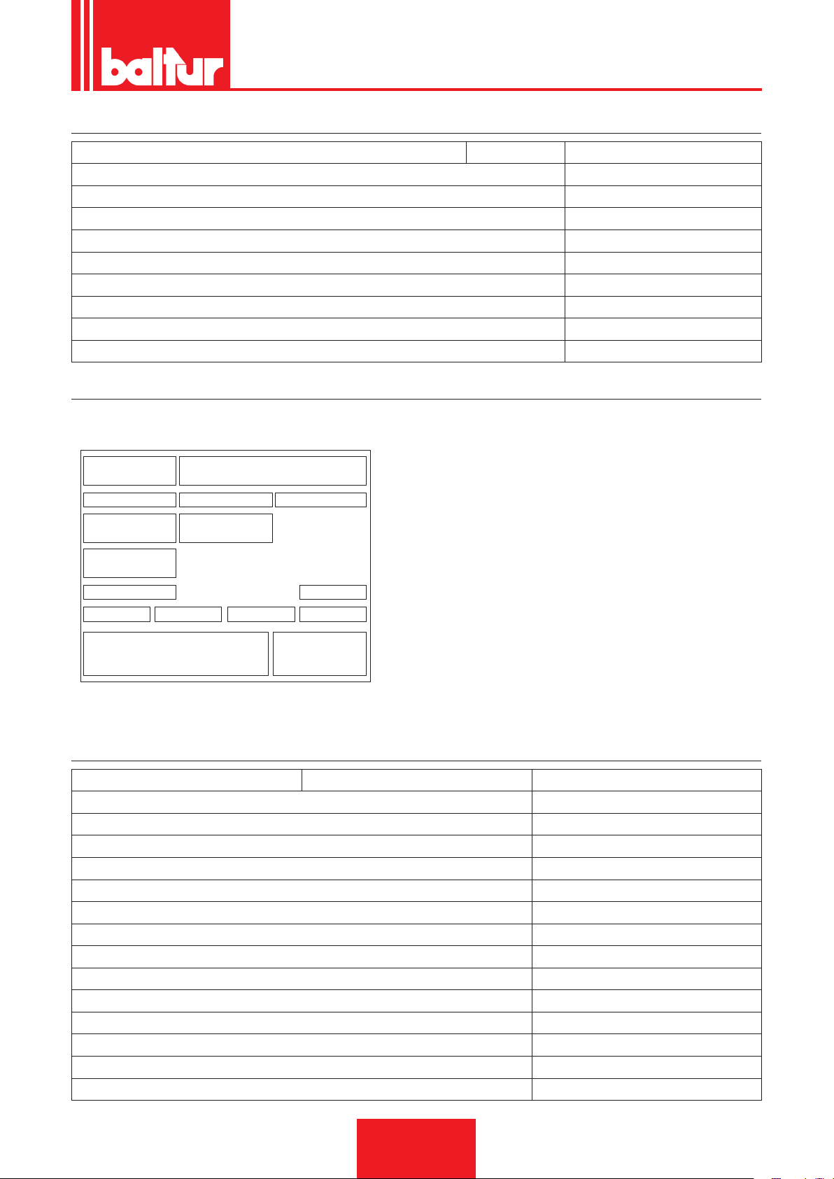
MATERIALE A CORREDO
Targa_descr_bru
MODELLO TBML 50MC
FLANGIA ATTACCO BRUCIATORE 1
GUARNIZIONE ISOLANTE 1
PRIGIONIERI N°4 - M12
DADI ESAGONALI N°4 - M12
RONDELLE PIANE N°4 - Ø12
CORDONE ISOLANTE 1
TUBI FLESSIBILI N°2 - 1/2"x1/2"
FILTRO 3/8"
NIPPLO/I N°2 - 1/2"x3/8"
TARGA IDENTIFICAZIONE BRUCIATORE
1 Logo aziendale
2 Ragione sociale azienda
3 Codice prodotto
1 2
3 4 5
6 7
8
9
10 13
11
12
14
1615
4 Modello bruciatore
5 Matricola
6 Potenza combustibili liquidi
7 Potenza combustibili gassosi
8 Pressione combustibili gassosi
9 Viscosità combustibili liquidi
10 Potenza motore ventilatore
11 Tensione di alimentazione
12 Grado di protezione
13 Paese di costruzione e numeri di certicato di omologazione
14 Anno di costruzione
15 16 Codice a barre matricola bruciatore
ITALIANO
DATI REGISTRAZIONE PRIMA ACCENSIONE
Modello: Data: ora:
Tipo di gas
Indice di Wobbe inferiore
Potere calorico inferiore
Portata gas
Portata min gas
Portata max gas
Potenza min gas
potenza max gas
Pressione gas di rete
Pressione gas a valle dello stabilizzatore
CO
CO2
temperatura fumi
temperatura aria
7 / 44
0006160003_201510
Stm3/h
Stm³/h
Stm³/h
kW
kW
mbar
mbar
Page 10
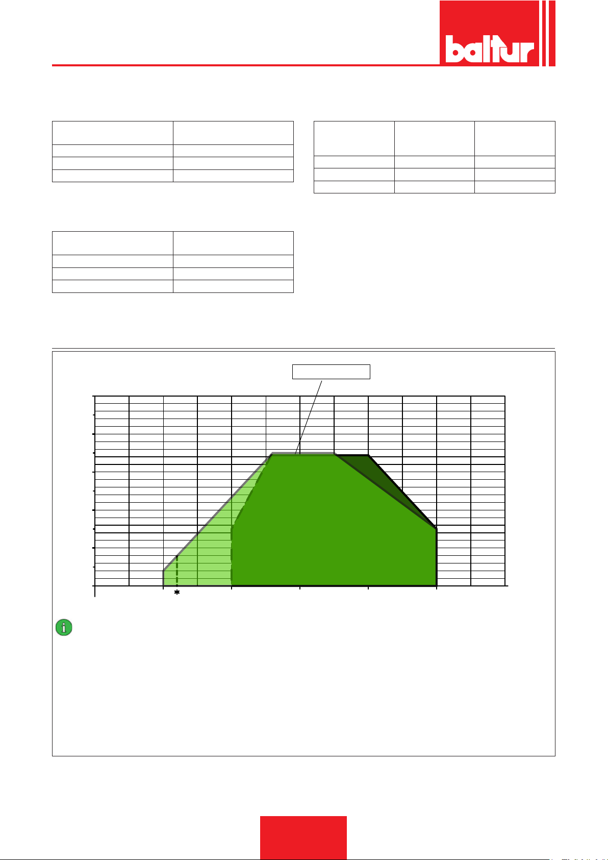
ITALIANO
¹) EMISSIONI GAS METANO
Classi denite secondo la normativa EN 676.
Classe
1 ≤ 170
2 ≤ 120
3 ≤ 80
Emissioni NOx in mg/kWh gas
²) EMISSIONI GAS PROPANO
Emissioni CO metano / propano ≤ 100 mg/kWh
Classe
1 ≤ 230
2 ≤ 180
3 ≤ 140
Emissioni NOx in mg/kWh gas
propano
CAMPO DI LAVORO
mbar
10
metano
³) EMISSIONI GASOLIO
Classi denite secondo la normativa EN 267.
Emissioni NOx in mg/
Classe
1 ≤ 250 ≤ 110
2 ≤ 185 ≤ 110
3 ≤ 120 ≤ 60
kWh combustibile
gasolio
TBML 50 ME / MC
Emissioni CO in mg/
kWh combustibile
gasolio
8
6
4
2
0
100 200 300 400
IMPORTANTE
I campi di lavoro sono ottenuti su caldaie di prova rispondenti alla norma EN267 per i combustibili liquidi e EN676 per i combustibili gassosi,
sono da considerarsi orientativi per gli accoppiamenti bruciatore-caldaia. Per il corretto funzionamento del bruciatore le dimensioni della camera di combustione devono essere rispondenti alla normativa vigente;
in caso contrario vanno consultati i costruttori.
Il bruciatore non deve operare al di fuori del campo di lavoro dato.
500
Potenza termica min TBML 50 gpl = 120kW
600
0002922890
kW
8 / 44
0006160003_201510
Page 11
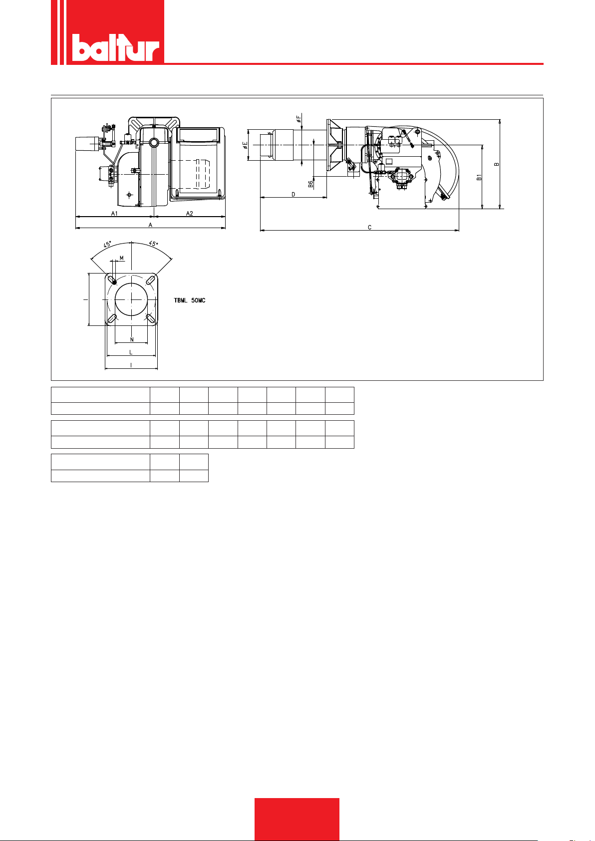
DIMENSIONI DI INGOMBRO
ITALIANO
0002471370N2
Modello A A1 A2 B B1 B6 C
TBML 50MC 770 400 370 455 325 160 1020
Modello D min D max E Ø F Ø I L min L max
TBML 50MC 170 340 156 152 260 225 300
Modello M N Ø
TBML 50MC M12 160
9 / 44
0006160003_201510
Page 12
ITALIANO
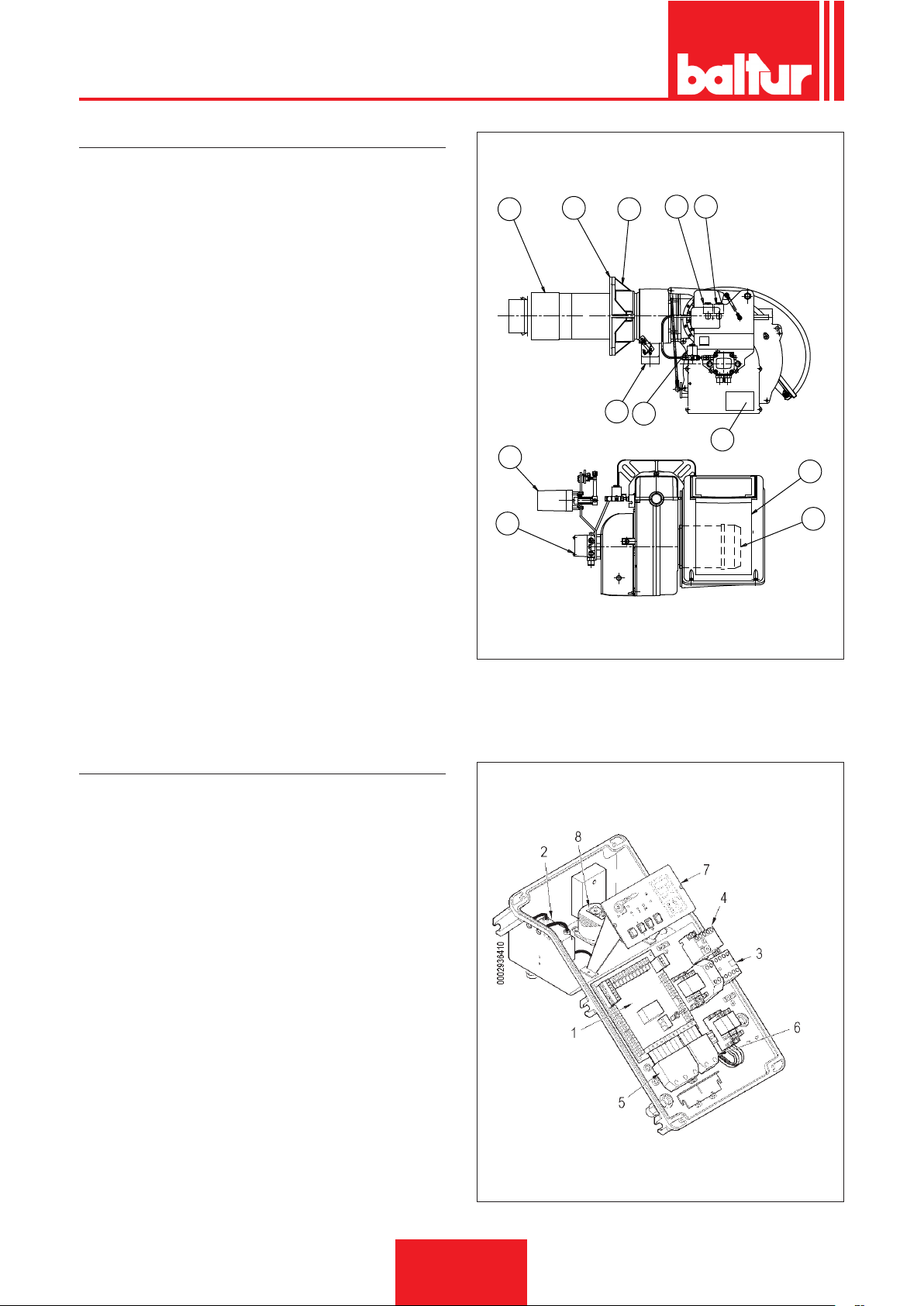
DESCRIZIONE COMPONENTI
1 Testa di combustione
2 Guarnizione
3 Flangia attacco bruciatore
4 Flangia attacco rampa gas
5 Elettrovalvola 1° stadio
6 Elettrovalvola di sicurezza
7 Elettrovalvola 2° stadio
8 Servomotore regolazione aria/gas
9 Pompa bruciatore
10 Quadro elettrico
11 Motore
12 Targa identicazione bruciatore
10
1
2
3
4
8 6
0002471370N1
7
14
12
QUADRO ELETTRICO
1 Apparecchiatura
2 Trasformatore d'accensione
3 Contattore motore
4 Relè termico
5 Connettore 7 poli
6 Connettore 4 poli
7 Pannello sinottico
8 Pressostato aria
11
13
10 / 44
0006160003_201510
Page 13
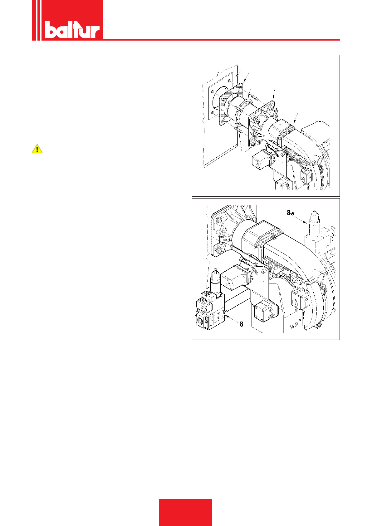
APPLICAZIONE DEL BRUCIATORE ALLA
0002937450
CALDAIA
ITALIANO
1
13
MONTAGGIO GRUPPO TESTATA
• Posizionare sul canotto la guarnizione isolante (13) interponen-
do la corda (2) tra la angia e guarnizione.
• Adeguare la posizione della angia di attacco (19) allentando le
viti (6), la testa del bruciatore dovrà penetrare nel focolare della
misura consigliata dal costruttore del generatore.
• Fissare il bruciatore (18) alla caldaia (1) tramite i prigionieri, le
rondelle e i relativi dadi in dotazione (7).
PERICOLO / ATTENZIONE
Sigillare completamente con materiale idoneo lo spazio tra
il cannotto del bruciatore e il foro sul refrattario all’interno
del portellone caldaia.
MONTAGGIO RAMPA GAS
La rampa gas è omologata secondo normativa EN 676 e viene
fornita separatamente.
Sono possibili diverse soluzioni di montaggio (8), (8a), della ram-
pa gas.
2
25
18
6
7
11 / 44
0006160003_201510
Page 14
ITALIANO
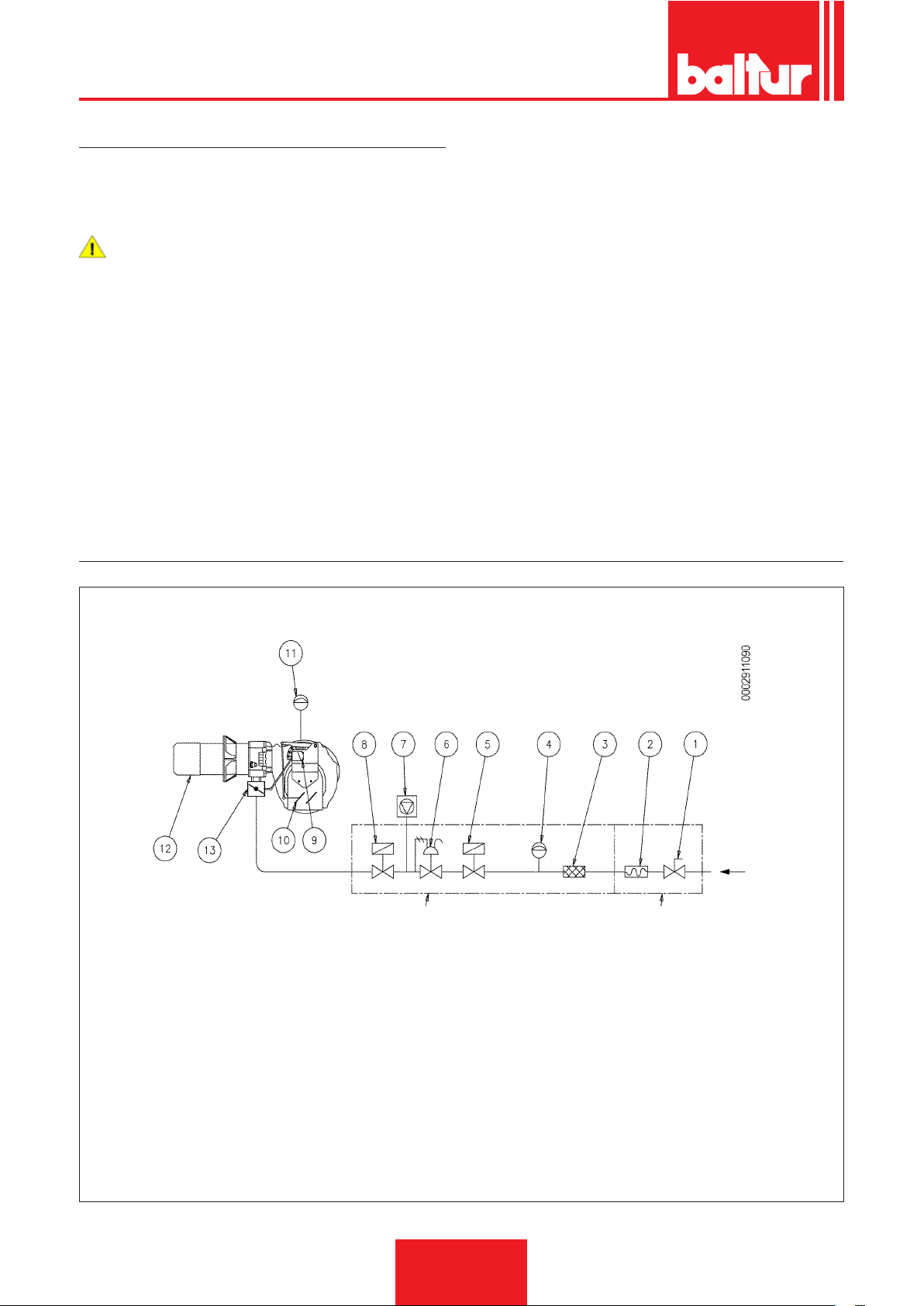
LINEA DI ALIMENTAZIONE GAS
Lo schema di principio della linea di alimentazione gas è riportato
nella gura sotto.
La rampa gas è omologata secondo normativa EN 676 e viene
fornita separatamente dal bruciatore.
PERICOLO / ATTENZIONE
Occorre installare, a monte della valvola gas, una valvola
di intercettazione manuale e un giunto antivibrante, disposti
secondo quanto indicato nello schema di principio.
SCHEMA DI PRINCIPIO BRUCIATORI A GAS
RAMPA GAS FORNITA DAL COSTRUTTORE A CURA DELL’INSTALLATORE
1 Valvola di intercettazione manuale
2 Giunto antivibrante
3 Filtro gas
4 Pressostato di minima pressione gas
5 Valvola di sicurezza
6 Regolatore di pressione
7 Dispositivo di controllo tenuta valvole (obbligatorio per bruciatore
con portata termica nominale massima superiore a 1200kW)
8 Valvola di lavoro ad apertura lenta
9 Servomotore regolazione aria/gas
10 Serranda regolazione aria
11 Pressostato aria
12 Testa di combustione
13 Valvola farfalla regolazione gas
12 / 44
0006160003_201510
Page 15
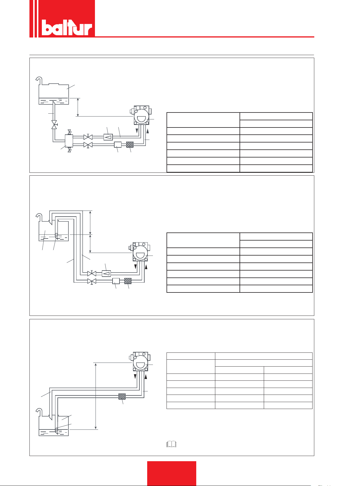
SCHEMI DIMENSIONAMENTO TUBAZIONE
0002900740N1
8
3
0002900740N2
ITALIANO
IMPIANTO DI ALIMENTAZIONE PER GRAVITA'
1
H
2
9
7
5
8 3
IMPIANTO A CADUTA CON ALIMENTAZIONE DALLA
SOMMITA' DEL SERBATOIO
1 Serbatoio
2 Tubazione di alimentazio-
ne
3 Filtro a rete
4 Pompa
5 Degasicatore
H L. Complessiva
4
Metri Øi 14 mm
6
1 30
1,5 35
2 35
2,5 40
3 40
1 Serbatoio
3 Filtro a rete
4 Pompa
6 Tubo di aspirazione
6 Tubo di aspirazione
7 Tubo di ritorno bruciatore
8 Dispositivo automatico in-
tercettazione a bruciatore
fermo
9 Valvola unidirezionale
Metri
7 Tubo di ritorno
8 Dispositivo automatico in-
tercettazione a bruciatore
fermo
9 Valvola unidirezzionale
10 Valvola di fondo
H P
10
1
7
6
IMPIANTO DI ALIMENTAZIONE IN ASPIRAZIONE
7
9
H
3
1
10
4
4
6
0002900740N3
H L. Complessiva
Metri
Metri Øi 14 mm
1 30
1,5 35
2 35
2,5 40
3 40
Quota P = 3,5 m. (Max)
1 Serbatoio
3 Filtro a rete
4 Pompa
H L.Complessiva
Metri
0,5 26 45
1 22 38
1,5 19 31
2 14 25
2,5 11 19
H - Dislivello fra min, livello in serbatoio e asse pompa
L - Lunghezza totale di ogni tubazione compreso il tratto verticale. Per
ogni gomito o saracinesca detrarre 0.25 .
CAUTELA / AVVERTENZE
Per eventuali organi mancanti nelle tubazioni attenersi alle nor-
me vigenti
6 Tubo di aspirazione
7 Tubo di ritorno
10 Valvola di fondo
Metri
Øi 14 mm Øi 16 mm
13 / 44
0006160003_201510
Page 16

ITALIANO
COLLEGAMENTI ELETTRICI
• Le linee elettriche devono essere distanziate dalle parti calde.
• L’installazione del bruciatore è consentita solo in ambienti con
grado di inquinamento 2 come indicato nell’allegato M della norma EN 60335-1:2008-07.
• Assicurarsi che la linea elettrica a cui si vuol collegare l’apparecchio sia alimentata con valori di tensione e frequenza adatti
al bruciatore.
• La linea di alimentazione trifase o monofase deve essere provvista di interruttore con fusibili. E’ inoltre richiesto, dalle Norme,
un interruttore sulla linea di alimentazione del bruciatore, posto
all’esterno del locale caldaia in posizione facilmente raggiungibile.
• La linea principale, il relativo interruttore con fusibili e l’eventuale limitatore, devono essere adatti a sopportare la corrente
massima assorbita dal bruciatore.
• Prevedere un interruttore onnipolare con distanza d’apertura
dei contatti uguale o superiore a 3 mm per l’allacciamento alla
rete elettrica, come previsto dalle normative di sicurezza vigenti.
• Per i collegamenti elettrici (linea e termostati) vedere il relativo
schema elettrico.
• Sguainare l’isolante esterno del cavo di alimentazione nella
misura strettamente necessaria al collegamento, evitando così
che il lo possa venire a contatto con parti metalliche.
Per eseguire il collegamento del bruciatore alla linea di alimenta-
zione procedere come segue:
• Rimuovere il coperchio svitando le viti (1), senza togliere lo
sportellino trasparente. In questo modo è possibile accedere al
quadro elettrico del bruciatore.
• Allentare le viti (2) e, dopo aver rimosso la piastrina stringicavi
(3), far passare attraverso il foro la spina a sette poli, l'eventuale a quattro poli e il cavo comando modulazione se previsto.
Collegare i cavi di alimentazione (4) al teleruttore, ssare il cavo
di terra (5) e serrare il relativo pressacavo.
• Riposizionare la piastrina stringicavi. Ruotare l’eccentrico (6) in
modo che la piastrina eserciti una adeguata pressione sui cavi,
quindi stringere le viti che ssano la piastrina. Collegare inne
le relative spine e il cavo comando modulazione se previsto.
1
0002934780a
1
4
5
3
2
0002934780b
14 / 44
0006160003_201510
0002934780c
6
Page 17
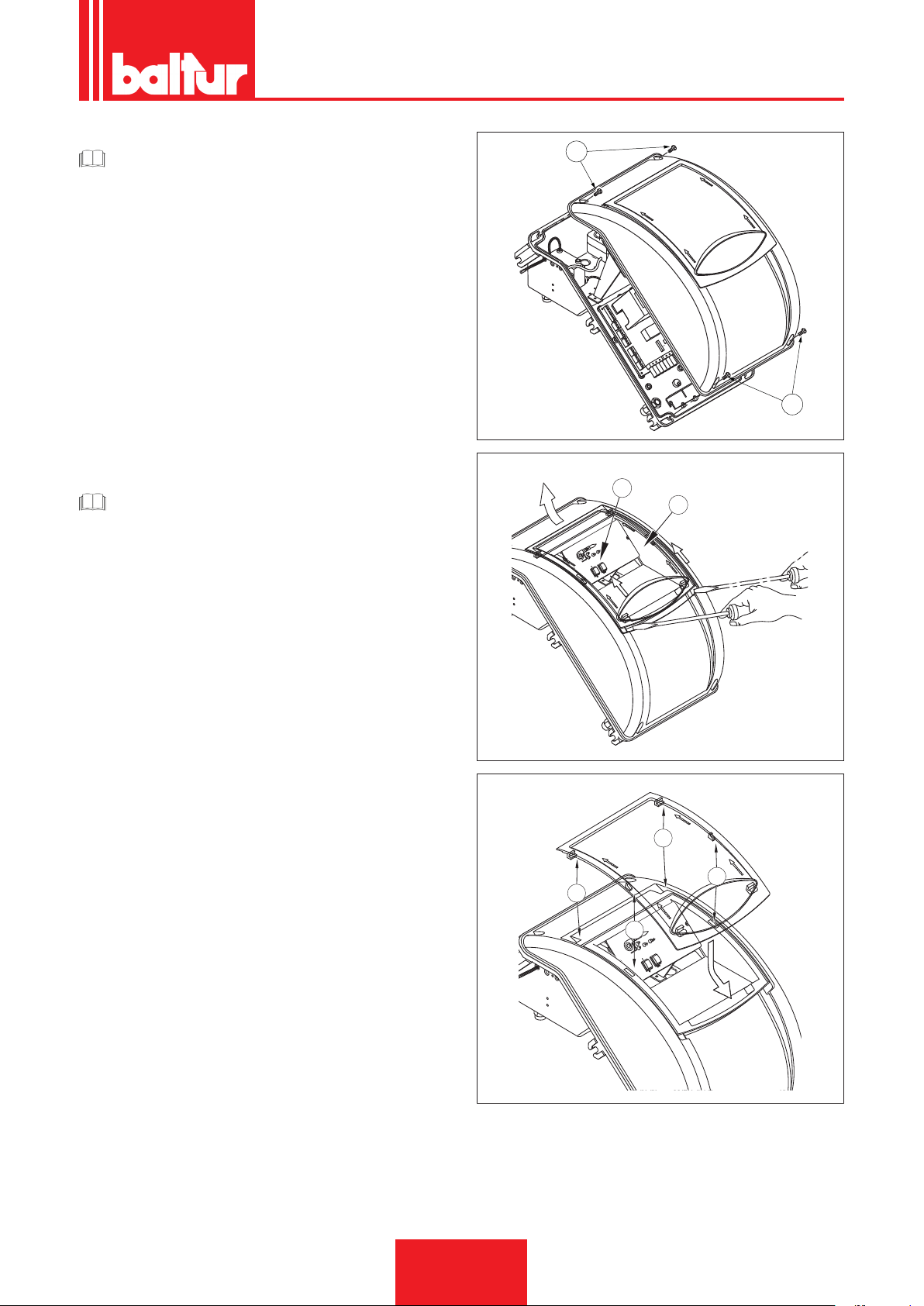
CAUTELA / AVVERTENZE
1
Gli alloggiamenti dei cavi per le spine sono previsti rispettivamente per cavo Ø 9,5÷10 mm e Ø 8,5÷9 mm, questo
per assicurare il grado di protezione IP 54 (Norma CEI
EN60529) relativamente al quadro elettrico.
• Per richiudere il coperchio del quadro elettrico, avvitare le viti
(1) esercitando una coppia di serraggio di circa 5 Nm per assi-
curare la corretta tenuta.
Per accedere al pannello comandi (8), fare scorrere lo sportellino
trasparente (7) per un breve tratto nella direzione della freccia indicata in gura esercitando una leggera pressione con un utensile
(esempio cacciavite) nella direzione delle freccce, farlo scorrere
per un breve tratto e separarlo dal coperchio.
• Per una corretta risistemazione dello sportellino trasparente sul
quadro procedere posizionando i ganci in corrispondenza delle
rispettive sedi (9), far scorrere lo sportellino nella direzione indicata dalla freccia no ad avvertire un leggero scatto così da
garantire la tenuta.
CAUTELA / AVVERTENZE
L’apertura del quadro elettrico del bruciatore è consentita
esclusivamente a personale professionalmente qualicato.
ITALIANO
0002934780a
1
8
7
0002934780d1
9
9
9
9
0002934780e
15 / 44
0006160003_201510
Page 18

ITALIANO
LINEA DI ALIMENTAZIONE GASOLIO
L'esposizione che segue tiene esclusivamente conto di quanto
necessario per assicurare un buon funzionamento.
L'apparecchio è dotato di pompa auto-aspirante capace quindi
di aspirare direttamente l'olio dalla cisterna anche per il primo
riempimento.Questa affermazione è valida purchè sussistano i
presupposti necessari, vedi schemi dimensionamento tubazioni.
Per assicurare un buon funzionamento è preferibile che le tubazioni, di aspirazione e ritorno, siano eseguite con raccordi saldati
evitando le giunzioni a letto che spesso consentono inltrazioni
di aria che disturbano il funzionamento della pompa e quindi del
bruciatore.
Dove sia indispensabile eseguire un raccordo smontabile, si impieghi il sistema a ange saldate con interposta guarnizione resistente al combustibile, che assicura un'ottima tenuta.Per impianti
dove la tubazione necessiti di un diametro relativamente modesto,
consigliamo l'impiego del tubo in rame.
Nelle inevitabili giunzioni, consigliamo l'impiego di raccordi a "bicono".
Di seguito sono riportati gli schemi di principio per diversi tipi di
impianti in funzione della posizione della cisterna rispetto al bruciatore.La tubazione di aspirazione dovrà essere disposta in salita
verso il bruciatore, per evitare accumulo di eventuali bolle di gas.
Nel caso in cui vengano installati più bruciatori in un unica sala
caldaie, è indispensabile che ogni bruciatore abbia un suo tubo
di aspirazione.
Solo i tubi di ritorno possono conuire in un unico tubo di sezione
adatta per raggiungere la cisterna. Evitare in ogni caso il collegamento diretto del tubo di ritorno sul tubo di aspirazione.
E' consigliabile coibentare convenientemente le tubazioni di aspi-
razione e di ritorno per evitare raffreddamenti funzionalmente
dannosi.I diametri delle tubazioni (da rispettare rigorosamente)
sono riportati nelle seguenti tabelle.
La depressione massima che la pompa può sopportare funzionando regolarmente e silenziosamente è di 0,47 bar; se tale valore viene superato, il regolare funzionamento della pompa non è
più garantito.
Pressione massima su aspirazione e ritorno = 1 bar.
POMPA AUSILIARIA
In alcuni casi (eccessiva distanza o dislivello) è necessario effettuare l'impianto con un circuito di alimentazione ad "anello",
con pompa ausiliaria, evitando quindi il collegamento diretto della
pompa del bruciatore alla cisterna.
In questo caso la pompa ausiliaria può essere messa in funzione
alla partenza del bruciatore e fermata all'arresto dello stesso.
Il collegamento elettrico della pompa ausiliaria si realizza collegando la bobina (230V) che comanda il teleruttore della pompa
stessa, ai morsetti 2 (N) e 17 del circuito stampato.
Si raccomanda di seguire sempre le prescrizioni sotto riportate:
• La pompa ausiliaria deve essere installata il più vicino possibile
al liquido da aspirare.
• La prevalenza deve essere adeguata all'impianto in questione.
• Consigliamo una portata almeno pari alla portata della pompa
del bruciatore.
• Le tubazioni di collegamento devono essere dimensionate in
funzione della portata della pompa ausiliaria.
• Evitare assolutamente il collegamento elettrico della pompa ausiliaria direttamente al teleruttore del bruciatore.
• Regolare la pressione a circa 0,5 bar ÷ 1 bar, se il circuito è
provvisto di regolatore di pressione.
16 / 44
0006160003_201510
Page 19
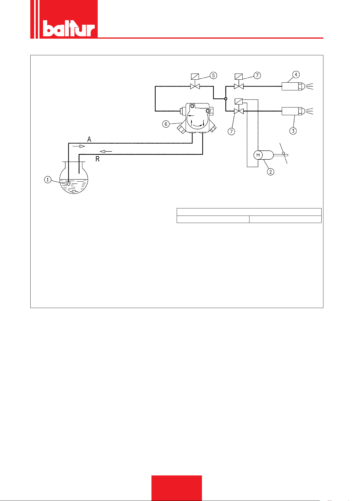
SCHEMA DI PRINCIPIO CIRCUITO IDRAULICO
ITALIANO
1 Valvola di fondo
2 Servomotore regolazione aria
3 Ugello 2° stadio
4 Ugello 1° stadio
5 Valvola di sicurezza normalmente chiusa
6 Pompa 12 bar
7 Valvola normalmente chiusa
A Aspirazione
R Ritorno
Perdita di carico circuito idraulico
TBML 50MC 1 bar
17 / 44
0006160003_201510
Page 20

ITALIANO
DESCRIZIONE DEL FUNZIONAMENTO
CON COMBUSTIBILE LIQUIDO
PRECISAZIONE PER L'ACCENSIONE DEL BRUCIATORE
MISTO
Si consiglia di effettuare prima l'accensione con combustibile liquido (selettore 2 in posizione OIL, accensione led OIL) perchè
l'erogazione è, in questo caso, condizionata dall'ugello utilizzato,
mentre l'erogazione del gas metano può essere variata a piacere
agendo sul relativo regolatore di portata.
E' sconsigliabile sovradimensionare il bruciatore alla caldaia per
riscaldamento e produzione di acqua calda sanitaria, in quanto
il bruciatore può lavorare anche per lunghi periodi ad una sola
amma, facendo lavorare la caldaia ad una potenzialità inferiore a
quella richiesta; di conseguenza, i prodotti di combustione (fumi)
escono ad una temperatura eccessivamente bassa (circa 180° C
per olio combustibile e 130°C per gasolio), dando luogo a presenza di fuliggine allo sbocco del camino.
Inoltre quando la caldaia lavora a potenzialità inferiori a quelle
indicate dai tecnici, è molto probabile la formazione di condensa
acida e di fuliggine in caldaia con conseguente rapido intasamento e corrosione della stessa.
Quando il bruciatore a due amme è installato su una caldaia per
produzione acqua ad uso riscaldamento, deve essere collegato
in modo da lavorare a regime normale con entrambe le amme,
arrestandosi completamente, senza passaggio alla prima amma,
quando la temperatura prestabilita viene raggiunta.
Per ottenere questo particolare funzionamento, non si installa il
termostato della seconda amma, e fra i rispettivi morsetti della
spina a quattro poli, si realizza di collegamento diretto (ponte).
In tal modo si utilizza solo la capacità del bruciatore di accendersi
a portata ridotta per realizzare una accensione dolce, condizione
indispensabile pe le caldaie con camera di combustione in pressione (pressurizzata), ma molto utile anche nelle caldaie normali
(camera di combustione in depressione). Il comando (inserzione
o arresto) del bruciatore è subordinato ai soliti termostati di eser-
cizio o sicurezza.
Chiudendo l'interruttore (1), se i termostati sono chiusi, la tensione
raggiunge l'apparecchiatura di comando e controllo (accensione
led 2) che inizia il suo ciclo di funzionamento. Vengono così inseriti il motore del ventilatore (led 3) e il trasformatore di accensione
(led 5).
Il motore mette in rotazione la ventola che effettua un lavaggio con
aria della camera di combustione e contemporaneamente la pompa del combustibile che determinano una circolazione nei condotti
espellendo, attraverso il ritorno, eventuali bolle di gas. Questa
fase di prelavaggio ha termine con l'apertura dell'elettrovalvole
di sicurezza e di 1° stadio (led 6) ciò consente al combustibile,
alla pressione di 12 bar, di raggiungere l'ugello del 1° stadio e da
questo, uscire in camera di combustione nemente polverizzato.
Appena il combustibile polverizzato esce dall'ugello viene incen-
diato dalla scarica presente tra gli elettrodi sin dalla partenza del
motore.
Durante l'accensione del primo stadio la serranda dell'aria è man-
tenuta nella posizione registrata sull'apposita camma del servomotore regolazione aria/gas.
Se compare regolarmente la amma, superato il tempo di sicurezza previsto dall'apparecchiatura, questa inserisce il servomotore
regolazione aria/gas che si porta in posizione di secondo stadio.
Nella fase di passaggio dal primo al secondo stadio il servomotore
inserisce l'elettrovalvola (normalmente chiusa) del secondo stadio
(led 4).
L'apertura della valvola del secondo stadio consente al gasolio,
alla pressione di 12 bar, di raggiungere il secondo ugello; portando il bruciatore al funzionamento a pieno regime.
Dal momento della comparsa della amma in camera di combustione il bruciatore è controllato e comandato dal dispositivo controllo amma e dai termostati.
L'apparecchiatura di comando prosegue il programma e stacca il
trasformatore d'accensione. Quando la temperatura o pressione
in caldaia raggiunge il valore a cui è tarato il termostato o pressostato, lo stesso interviene determinando l'arresto del bruciatore.
Successivamente, per l'abbassarsi della temperatura o pressione
al di sotto del valore di richiusura del termostato o pressostato, il
bruciatore viene nuovamente acceso.
Se per qualsiasi motivo, durante il funzionamento viene a mancare la amma, interviene immediatamente (tempo un secondo)
il dispositivo controllo amma che interrompendo l'alimentazione
del relè, provocando la disinserzione delle elettrovalvole che intercettano il usso di combustibile agli ugelli.
Si ripete così la fase di accensione e, se la amma si riaccende normalmente, il funzionamento del bruciatore riprende regolarmente, in caso contrario (amma irregolare o completamente
assente) l'apparecchio si porta automaticamente in blocco (accensione led 5).
18 / 44
0006160003_201510
Page 21
ITALIANO
Display_TBML_80pn
Se il programma viene interrotto (mancanza di tensione, intervento manuale, intervento di termostato, ecc.) durante la fase di
prelavaggio il programmatore ritornerebbe nella sua posizione
iniziale e ripeterebbe automaticamente tutta la fase di accensione
del bruciatore.
CAUTELA / AVVERTENZE
La scelta degli ugelli in funzione della portata totale desiderata (2 ugelli in funzione), deve essere effettuata tenendo
conto dei valori di portata corrispondenti alla pressione di
lavoro di 12 bar del gasolio. Sostituendo gli ugelli è possibi-
le variare notevolmente il rapporto tra il primo e il secondo
stadio.
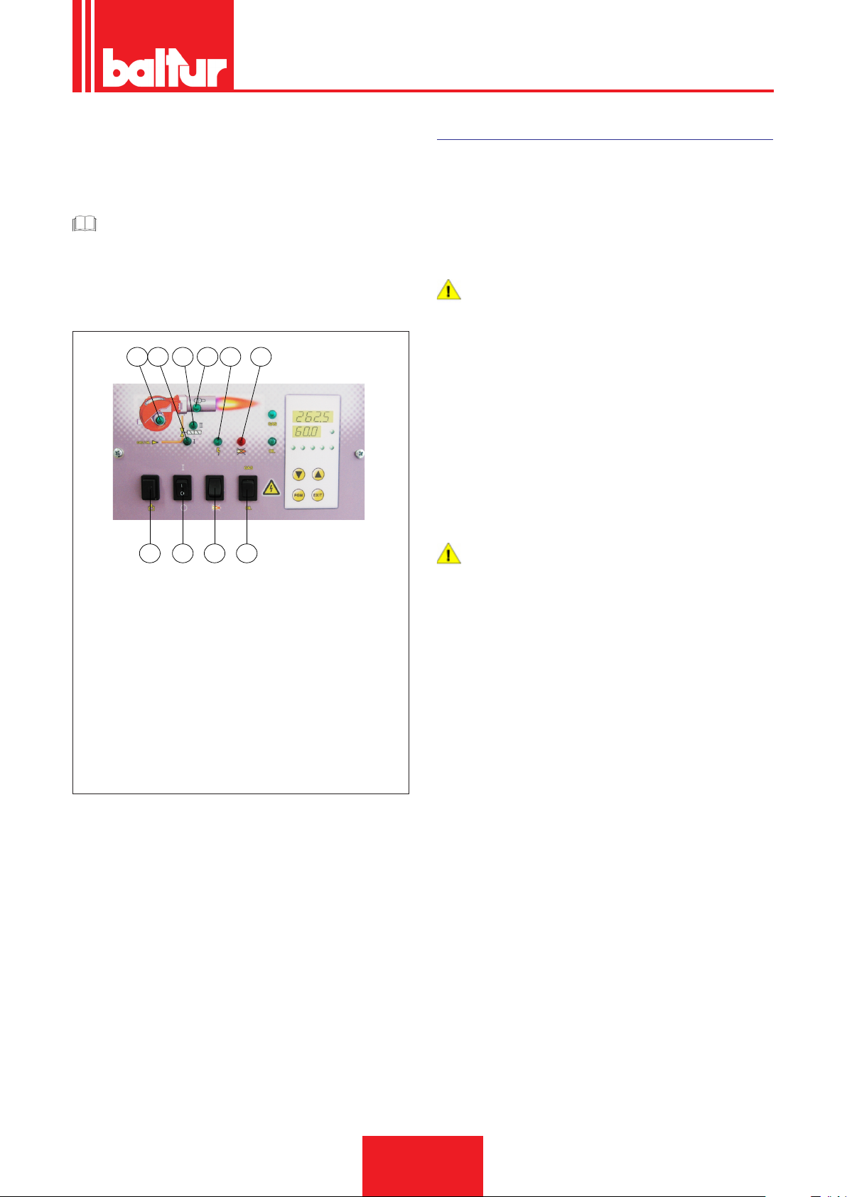
3 6 4 5 2 7
PRIMO RIEMPIMENTO TUBAZIONE
Dopo aver controllato che i tappi di protezione in plastica posti
sugli attacchi della pompa siano stati asportati, si procede come
segue:
• Portare nella posizione "O" l'interruttore posto sul bruciatore in
modo da evitare l'inserzione automatica del bruciatore.
• Assicurarsi che la tensione di linea sia la stessa indicata in targa identicazione del bruciatore.
PERICOLO / ATTENZIONE
Attendere, per stabilire con sicurezza il senso di rotazione,
che la ventola giri molto lentamente poichè è possibile una
interpretazione errata del senso di rotazione.
• Staccare se già sono stati collegati, i tubi essibili dalla tubazione di aspirazione e da quella di ritorno.
• Immergere l'estremità del tubo essibile di aspirazione in un
recipiente contenente olio lubricante o gasolio(non impiegare
prodotti con bassa viscosità come petrolio, kerosene, ecc.).
• Premere ora sul pulsante (9) del quadro di comando per mettere in funzione il motore stesso e quindi la pompa. Attendere
che la pompa abbia aspirato una quantità di lubricante pari a
1 o 2 bicchieri, quindi fermare. Questa operazione ha lo scopo
di evitare il funzionamento della pompa a secco e di aumentare
il potere aspirante.
9 1 8 10
1 Interruttore generale ACCESO / SPENTO
2 Selettore combustibile.
3 Spia funzionamento combustibile liquido.
5 Spia funzionamento combustibile gassoso.
4 Spia blocco apparecchia-
tura.
6 Spia funzionamento 1°
stadio
7 Spia blocco apparecchia-
tura
8 Pulsante sblocco appa-
recchiatura
9 Pulsante caricamento
combustibile
10 Selettore combustibile
PERICOLO / ATTENZIONE
Le pompe che lavorano a 2800 giri non devono assolutamente lavorare a secco, perchè si bloccherebbero (grippaggio) in brevissimo tempo.
• Collegare ora il essibile al tubo di aspirazione ed aprire tutte le
eventuali saracinesche poste su questo tubo, nonchè ogni altro
eventuale organo di intercettazione del combustibile.
• Premere nuovamente il pulsante (9) per mettere in funzione la
pompa che aspira il combustibile dalla cisterna.
• Quando si vede uscire il combustibile dal tubo di ritorno (non
ancora collegato) fermare.
19 / 44
0006160003_201510
Page 22

ITALIANO
PERICOLO / ATTENZIONE
Se la tubazione è lunga, può essere necessario sfogare
l'aria dall'apposito tappo, se la pompa non ne è provvista,
asportare il tappo dell'attacco manometro.
• Collegare il tubo essibile di ritorno alla tubazione ed aprire le
saracinesche poste su questo tubo. Il bruciatore è così pronto
per essere acceso.
ACCENSIONE E REGOLAZIONE COMBUSTIBILE LIQUIDO
Prima dell'accensione è necessario assicurarsi che:
• Sia selezionato il tipo di combustibile corretto.
• I collegamenti con la linea di alimentazione, con i termostati
o pressostati, siano eseguiti esattamente secondo lo schema
elettrico dell'apparecchiatura.
• Ci sia combustibile in cisterna e acqua nella caldaia.
• Tutte le saracinesche poste sulla tubazione di aspirazione e ritorno dell'olio combustibile siano aperte e così pure ogni altro
organo di intercettazione del combustibile.
• Lo scarico dei prodotti di combustione possa avvenire liberamente (serranda della caldaia e del camino aperte).
• Accertarsi che la testa di combustione penetri nel focolare nella
misura richiesta dal costruttore della caldaia. Vericare che il
dispositivo di chiusura aria sulla testa di combustione sia nella
posizione adatta a garantire una corretta combustione, il passaggio dell'aria tra disco e testa deve essere sensibilmente
ridotto nel caso di erogazione combustibile ridotta. Con un'erogazione di combustibile elevata anche il passaggio aria dovrà
aumentare di conseguenza, vedere capitolo "REGOLAZIONE
DELLA TESTA DI COMBUSTIONE".
• Gli ugelli applicati sul bruciatore siano adatti alla potenzialità
della caldaia e, se necessario, sostituirli con altri. In nessun
caso la quantità di combustibile erogata deve essere superiore
a quella massima richiesta dalla caldaia e a quella massima
ammessa per il bruciatore.
Per l'accensione si procede come segue:
PERICOLO / ATTENZIONE
Impedire il funzionamento della seconda amma evitando
di collegare il connettore 4 poli (2°stadio).
• Regolare l'aria della quantità che si presume necessaria per
l'accensione al 1° stadio attraverso la camma specica del ser-
vomotore regolazione aria/gas .
• Inserire l'interruttore generale e quello del quadro comando.
• Si inserisce il programmatore che incomincia a svolgere il programma prestabilito, inserendo i dispositivi del bruciatore.L'apparecchio si accende come descritto nel capitolo "DESCRIZIONE DEL FUNZIONAMENTO".
20 / 44
0006160003_201510
Page 23
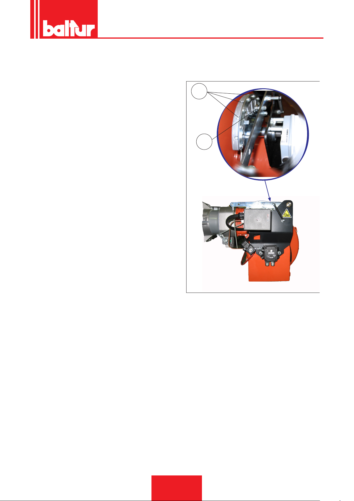
• Quando il bruciatore è in funzione al 1° stadio, si provvede a
img 010.jpg
regolare l'aria nella quantità necessaria per assicurare una buona combustione, vedi "REGOLAZIONE ARIA SULLA TESTA DI
COMBUSTIONE" e 0002937920 per la regolazione camma 1°
stadio gasolio.
• Dopo aver regolato l'aria per il 1° stadio si ferma il bruciatore,
togliendo corrente dall'interruttore generale, si chiude il circuito
elettrico che comanda l'inserzione del secondo stadio collegando il connettore 4 poli come da schema elettrico.
• Regolare l'aria della quantità che si presume necessaria per la
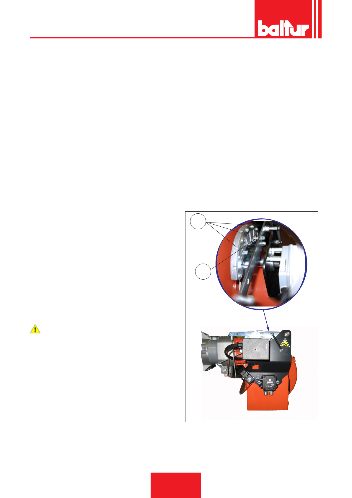
portata massima (2° stadio) agendo sulla vite/i in corrispondenza del cuscinetto (12).
- rotazione oraria la portata d'aria aumenta
- rotazione antioraria la portata diminuisce
• Si inserisce ora nuovamente l’apparecchio che si avvia e passa
automaticamente, secondo il programma stabilito dal programmatore, al secondo stadio.
ITALIANO
12
acc_reg001.psd
13
21 / 44
0006160003_201510
Page 24

ITALIANO
AN 47 - 57 - 67 - 77 - 97
PARTICOLARI POMPA
2 Attacco manometro e sfogo aria (1/8"G)
3 Vite regolazione pressione AN77... 10 - 20bars
4.1 Ritorno con grano di by-pass interno
5 Aspirazione
6 Mandata all'ugello
7 Attacco vuotometro (1/8"G)
7.1 Attacco vuotometro e grano di BY-PASS interno
CAUTELA / AVVERTENZE
La pompa viene pre regolata ad una pressione di 12 bar
4.1 5
2
2
3
6
67
0002900331
22 / 44
0006160003_201510
Page 25
ITALIANO
Display_TBML_80pn
DESCRIZIONE DEL FUNZIONAMENTO
CON COMBUSTIBILE GASSOSO
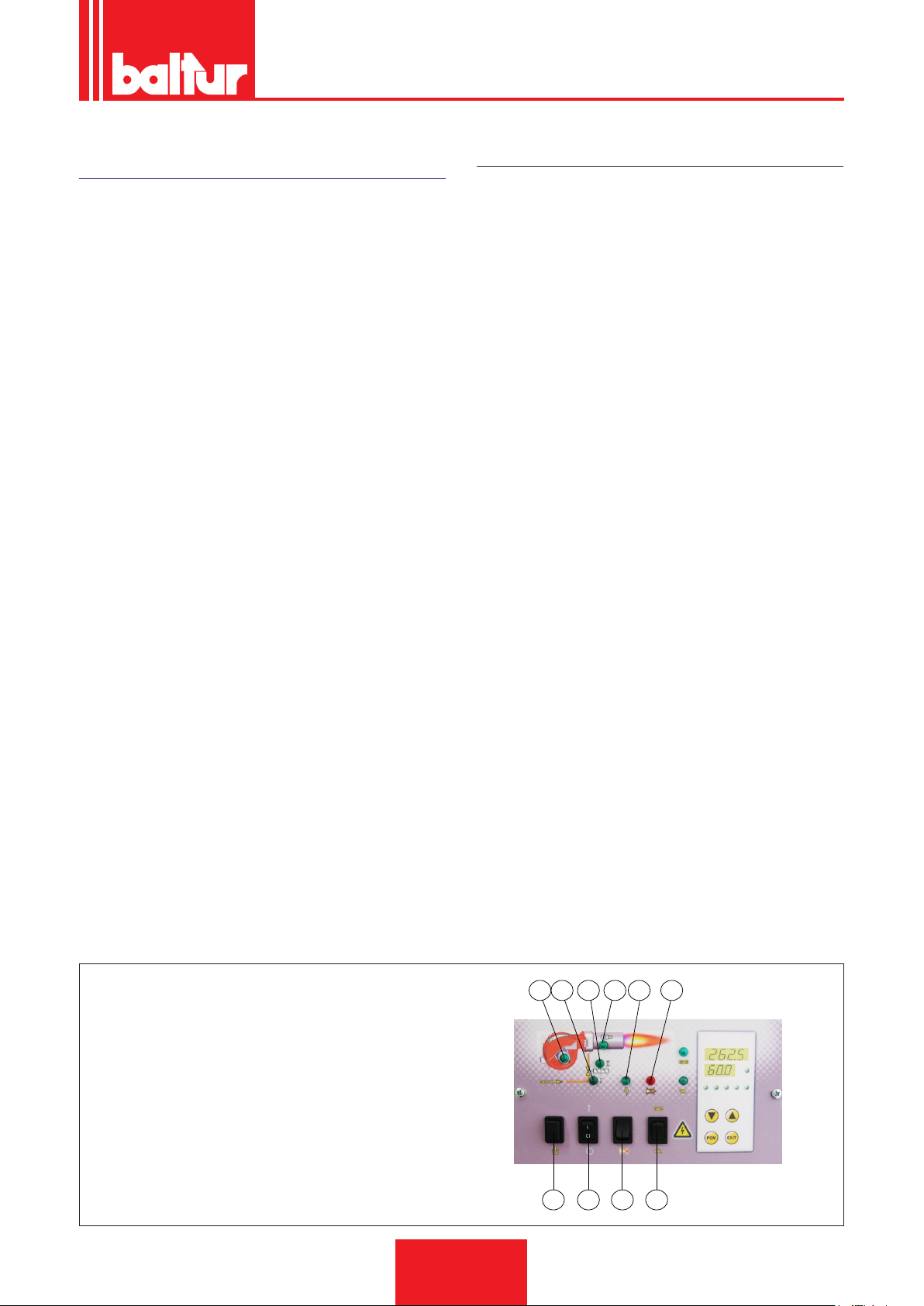
Chiudendo l'interruttore "1", se i termostati sono chiusi, la tensione
raggiunge l'apparecchiatura di comando e controllo (accensione
led 2) che inizia il suo funzionamento.
Viene così inserito il motore del ventilatore (led 3) per effettuare
la preventilazione della camera di combustione, contemporanea-
mente il servomotore di comando della serranda dell'aria si porta
nella posizione di apertura corrispondente alla massima potenza
regolata.
Al termine della fase di preventilazione la serranda dell'aria viene
riportata nella posizione di 1°amma. Se il pressostato di controllo
della pressione dell'aria di ventilazione rileva pressione sufciente, si inserisce il trasformatore d'accensione (led 5) e, dopo due
secondi, si aprono le valvole del gas principali e di sicurezza.
Precisiamo che:
• La valvola principale è di tipo monostadio ad apertura lenta
• La valvola di sicurezza è in versione ON/OFF
• La serranda dell'aria è azionata da un apposito servomotore
elettrico, tenere presente che all'arresto del bruciatore per intervento del termostato, la serranda viene riportata dal servomoto-
re nella posizione di chiusura.
La presenza della amma, rilevata dal dispositivo di controllo della
stessa, consente il proseguimento e il completamento della fase di
accensione con la disinserzione del trasformatore di accensione.
Nel caso di assenza amma, l'apparecchiatura si arresta in "blocco di sicurezza" (spia blocco 7) entro tre secondi dall'apertura della valvola principale. In caso di blocco di sicurezza le valvole vengono immediatamente richiuse. Per sbloccare l'apparecchiatura
dalla posizione di sicurezza premere il pulsante "8" sul pannello
comandi.
DESCRIZIONE DEL FUNZIONAMENTO DELLA MODULAZIONE
Quando il bruciatore è acceso alla portata minima, se la sonda di
modulazione lo consente (regolata ad un valore di temperatura o
pressione superiore a quella esistente in caldaia) il servomotore
di regolazione aria / gas inizia a girare;
• rotazione oraria la portata d’aria aumenta,
• rotazione antioraria la portata d’aria diminuisce.
determinando un aumento graduale dell’erogazione di aria di
combustione e, di conseguenza del gas, no a raggiungere l’erogazione massima cui il bruciatore è stato regolato.
Il bruciatore resta nella posizione di massima erogazione no a
quando la temperatura o pressione raggiunge un valore sufcien-
te a determinare l’intervento della sonda di modulazione che fa
ruotare il servomotore di regolazione aria in senso inverso a quel-
lo precedente.
La rotazione all’indietro e quindi la riduzione dell’erogazione aria e
gas, avviene a brevi intervalli di tempo.
Con questa manovra il sistema di modulazione cerca di equilibrare la quantità di calore fornito alla caldaia con quello che la stessa
cede all’utilizzo.
La sonda di modulazione applicata alla caldaia rileva le variazioni
di richiesta ed automaticamente provvede a adeguare l’erogazio-
ne di combustibile e di aria comburente inserendo il servomotore
di regolazione aria / gas con rotazione in aumento oppure in diminuzione.
Se anche con erogazione al minimo si raggiunge il valore limite
(temperatura o pressione) cui è regolato il dispositivo di arresto
completo (termostato o pressostato) il bruciatore viene arrestato
dall’intervento dello stesso.
Riabbassandosi la temperatura o pressione al di sotto del valore di
intervento del dispositivo di arresto il bruciatore viene nuovamente
inserito secondo il programma descritto nel paragrafo precedente.
1 Interruttore generale ACCESO / SPENTO
2 Selettore combustibile.
3 Spia funzionamento combustibile liquido.
5 Spia funzionamento combustibile gassoso.
4 Spia blocco apparecchiatura.
6 Spia funzionamento 1° stadio
7 Spia blocco apparecchiatura
8 Pulsante sblocco apparecchiatura
9 Pulsante caricamento combustibile
10 Selettore combustibile
3 6 4 5 2 7
9 1 8 10
23 / 44
0006160003_201510
Page 26
ITALIANO
img 010.jpg
ACCENSIONE E REGOLAZIONE GAS
METANO
• Posizionare la camma regolazione portata gas di prima amma
sul servomotore elettrico ad un angolo di apertura indicativamente tra i 15° - 20°.
• Inserire ora l’interruttore Interruttore MARCIA / ARRESTO del
quadro bruciatore; l’apparecchiatura di comando riceve così
tensione ed il programmatore determina l’inserzione del bru-
ciatore come descritto nel capitolo “descrizione del funzionamento”. Durante la fase di preventilazione occorre accertarsi
che il pressostato di controllo della pressione dell’aria effettui lo
scambio (da posizione di chiuso senza rilevamento di pressione, deve passare nella posizione di chiuso con rilevamento di
pressione dell’aria). Se il pressostato aria non rileva la pressione sufciente non viene inserito il trasformatore di accensione
e nemmeno le valvole del gas, pertanto l’apparecchiatura si
arresta in “blocco”.
• Alla prima accensione possono vericarsi “blocchi” successivi
dovuti a:
• Lo sfogo dell’aria dalla tubazione del gas non è stato eseguito
correttamente e quindi la quantità di gas è insufciente per consentire una amma stabile.
• Il “blocco” con presenza di amma può essere causato da instabilità della stessa, per un rapporto aria/gas non corretto. Si
rimedia variando la quantità di aria e/o di gas erogati in modo da
trovare il corretto rapporto. Lo stesso inconveniente può essere
causato da una non corretta distribuzione aria/gas nella testa di
combustione; agendo sul dispositivo di regolazione della testa
di combustione chiudere o aprire il passaggio dell’aria tra testa
e diffusore gas.
• Correggere la portata d'aria erogata in primo stadio, agendo
sulla vite/i (12) in corrispondenza del cuscinetto (13).
- Rotazione oraria la portata d'aria aumenta
- Rotazione antioraria la portata d'aria diminuisce
• Dopo aver completato la regolazione per la prima accensione,
spegnere il bruciatore e chiudere il circuito elettrico che coman-
da l'inserzione del secondo stadio.
• Regolare la portata di gas agendo sul regolatore di pressione
della valvola, no ad ottenere valori corretti di combustione,
senza modicare la precedente regolazione aria fatta per il ga-
solio. Consultare le istruzioni relative al modello di valvola gas
a singolo stadio installata. Evitare di mantenere in funzione il
bruciatore se la portata termica bruciata è superiore a quella
massima ammessa per la caldaia, onde evitare possibili danni
alla stessa.
• Vericare con gli appositi strumenti i parametri di combustione
(CO2 MAX= 10% O2 MIN= 3% CO MAX=0,1%)
Terminata la regolazione del bruciatore in secondo stadio, aprire
il circuito elettrico che comanda l'inserzione del 2° stadio senza
variare la regolazione della valvola gas già effettuata al punto precedente.
• Regolare la portata di gas di 1° stadio al valore desiderato
agendo, sul servomotore elettrico.
• Correggere se necessario l'erogazione di aria comburente operando sulle vite/viti (12) come descritto precedentemente.
• Vericare con gli appositi strumenti i parametri di combustione
in primo stadio (CO2 MAX=10% O2 MIN= 3% CO MAX=0,1%)
12
acc_reg001.psd
13
PERICOLO / ATTENZIONE
Vericare che la camma di regolazione portata gas di se-
condo stadio del servomotore elettrico sia posizionata a
130°.
• Inserire nuovamente il bruciatore chiudendo l'interruttore generale (1) sul pannello sinottico. Il bruciatore si accende e automa-
ticamente si porta in secondo stadio. Con l'ausilio degli appositi
strumenti, provvedere alla regolazione dell'erogazione di aria e
gas secondo la procedura di seguito descritta:
0006160003_201510
24 / 44
Page 27

ITALIANO
• Il pressostato aria ha lo scopo di impedire l’apertura delle valvole gas se la pressione dell’aria non è quella prevista. Il pressostato deve quindi essere regolato per intervenire chiudendo il
contatto quando la pressione dell’aria nel bruciatore raggiunge
il valore sufciente. Qualora il pressostato aria non rilevi una
pressione superiore a quella di taratura, l’apparecchiatura ese-
gue il suo ciclo ma non si inserisce il trasformatore d’accensione
e non si aprono le valvole del gas e di conseguenza il bruciatore
si arresta in “blocco”. Per accertare il corretto funzionamento
del pressostato aria occorre, con bruciatore acceso, in prima
amma, aumentarne il valore di regolazione no a vericarne
l’intervento a cui deve conseguire l’immediato arresto in “blocco” del bruciatore. Sbloccare il bruciatore, premendo l’apposito
pulsante e riportare la regolazione del pressostato ad un valore
sufciente per rilevare la pressione di aria esistente durante la
fase di funzionamento relativa al 1° stadio.
• Il pressostato di controllo della pressione del gas (minima) ha
lo scopo di impedire il funzionamento del bruciatore quando la
pressione del gas non risulta quella prevista. Dalla funzione
specica del pressostato risulta evidente che il pressostato di
controllo della pressione minima deve utilizzare il contatto che
si trova chiuso quando il pressostato rileva una pressione superiore a quella a cui è regolato.
PERICOLO / ATTENZIONE
Ultimate le regolazioni, accertarsi visivamente che la lamina su cui agisce il cuscinetto abbia un prolo progressivo.
Vericarne inoltre, con gli appositi strumenti che durante i
passaggi da 1° a 2° stadio i parametri di combustione non
si discostino eccessivamente dai valori ottimali.
FOTOCELLULA UV
Una leggera untuosità compromette fortemente il passaggio
dei raggi ultravioletti attraverso il bulbo della fotocellula UV impedendo che, l'elemento sensibile interno, riceva la quantità di
radiazione necessaria per un corretto funzionamento. Nel caso
di imbrattamento del bulbo con gasolio, olio combustibile ecc.., è
indispensabile pulire adeguatamente.
CAUTELA / AVVERTENZE
Il semplice contatto con le dita può lasciare una leggera untuosità, sufciente a compromettere il funzionamento della
fotocellula UV.
La cellula UV non rileva la luce del giorno o di una comune lam-
pada. L'eventuale verica di sensibilità può essere fatta con la
amma (accendino, candela) oppure con la scarica elettrica che
si manifesta tra gli elettrodi di un comune trasformatore d'accensione. Per assicurare un buon funzionamento il valore della
corrente di cellula UV deve essere sufcientemente stabile e non
scendere al di sotto del valore minimo richiesto dall'apparecchiatura specica, detto valore è riportato nello schema elettrico. Può
essere necessario ricercare sperimentalmente la miglior posizione facendo scorrere (spostamento assiale o di rotazione) il corpo che contiene la fotocellula rispetto alla fascetta di ssaggio.
La verica si effettua inserendo un micro-amperometro, con una
scala adeguata, in serie ad uno dei due cavi di collegamento della fotocellula UV, ovviamente occorre rispettare la polarità + e -.
L'apparecchiatura ...necessità di una corrente di cellula compresa
tra 200 e 500microA.
25 / 44
0006160003_201510
Page 28
ITALIANO
0002937500
CONTROLLI
• Acceso il bruciatore occorre controllare i dispositivi di sicurezza
(rilevatore amma, blocco, termostati)
• Il dispositivo di controllo amma, deve essere in grado di intervenire durante il funzionamento, nel caso che la amma si
spenga (questo controllo deve essere effettuato dopo almeno 1
minuto dall'avvenuta accensione)
• Il bruciatore deve essere in grado di portarsi in blocco e restarci quando, in fase di accensione e nel tempo prestabilito
dall'apparecchiatura di comando, non compare regolarmente la
amma. Il blocco comporta l'arresto immediato del motore e
quindi del bruciatore, e l'accensione della corrispondente segnalazione luminosa di blocco. Per controllare l'efcienza del
rilevatore amma e del blocco, operare come segue:
- Mettere in funzione il bruciatore.
- Dopo almeno un minuto dall'avvenuta accensione estrarre
il rilevatore amma slandolo dalla sua sede, oscurarlo
simulando così la mancanza di amma (chiudere con uno
straccio l'apertura dedicata al rilevatore amma). La amma
del bruciatore deve così spegnersi. L'apparecchiatura
nel tempo determinato dal programma, si porta in blocco.
Sbloccare l'apparecchiatura solo con un intervento manuale
pigiando sull'apposito pulsante.
- Per controllare l'efcienza dei termostati, si fa funzionare il
bruciatore no a quando l'acqua in caldaia raggiunge la temperatura di almeno 50°C, e quindi, si agisce sulla manopola
di comando del termostato nel senso di abbassare la temperatura no ad avvertire lo scatto di apertura e contemporaneamente l'arresto del bruciatore. Lo scatto del termostato
deve avvenire con uno scarto massimo di 5 ¸ 10°C rispetto
al termometro di controllo (termometro di caldaia) in caso
contrario modicare la taratura della scala del termostato
facendola corrispondere a quella del termometro.
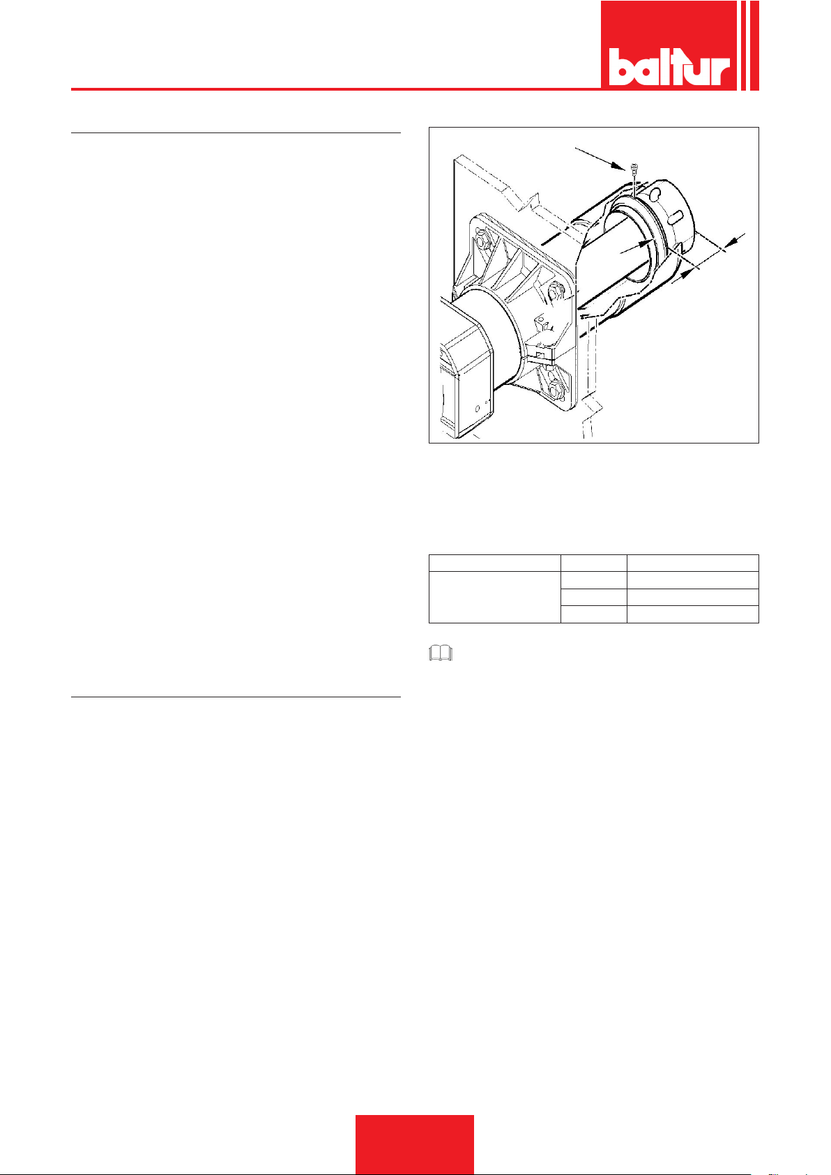
REGOLAZIONE ARIA SULLA TESTA DI COMBUSTIONE
La testa di combustione è dotata di un dispositivo di regolazione
che permette di aprire o chiudere il passaggio dell’aria tra il disco
e la testa.
Chiudendo il passaggio aria si riesce così ad ottenere un’elevata
pressione a monte del disco anche con basse portate.
L’elevata velocità e turbolenza dell’aria consente una migliore miscelazione con il combustibile e quindi, un’ottima stabilità di amma.Può essere indispensabile avere un’elevata pressione d’aria
a monte del disco per evitare pulsazioni di amma, condizione
indispensabile quando il bruciatore lavora su focolare pressuriz-
zato e/o ad alto carico termico.
Pertanto, il dispositivo di regolazione aria sulla testa di combustione, deve essere portato in una posizione tale da ottenere sempre
dietro al disco, un valore decisamente elevato di pressione.
Correggere la posizione del dispositivo chiusura aria della testa
di combustione, spostandolo in avanti o indietro, in modo da avere un usso d’aria adeguato all’erogazione, con serranda aria in
aspirazione sensibilmente aperta.
Per ottenere questo è necessario ssare il dispositivo in una posizione intermedia sulla chiusura aria sulla testa, ed agire sul dispositivo serranda aria aumentando il usso all’aspirazione della
ventola; ovviamente questa condizione si deve vericare quando
il bruciatore lavora alla massima potenza richiesta dall'impianto.
1
2
X
X = Distanza testa-disco; regolare la distanza X seguendo le in-
dicazioni:
• Regolare la distanza X dell'anello regolazione aria (2) secondo
le indicazioni della tabella.
• Serrare la vite (1).
BRUCIATORE X POTENZA kW
65 ÷ 66 260 ÷ 350
TBML 50 MC / ME
CAUTELA / AVVERTENZE
Le regolazione sopra esposte sono indicative; posizionare
la testa di combustione in funzione delle caratteristiche del
focolare.
70 ÷ 71 350 ÷ 430
78 ÷ 79 430 ÷ 500
26 / 44
0006160003_201510
Page 29
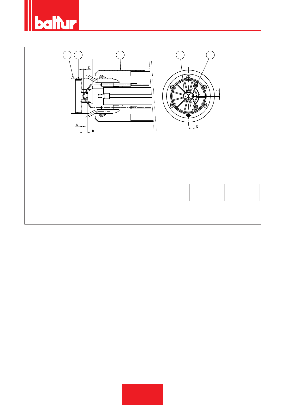
SCHEMA DI REGOLAZIONE DISTANZA DISCO ELETTRODI
12 3 5 4
ITALIANO
0002937420
1 - Diffusore
2 - Diffusore interno
3 - Disco amma
4 - Elettrodo accensione
5 - Ugelli
6 - Canotto porta ugelli
UGELLI CONSIGLIATI = MONARCH tipo 30° HV°
Dopo aver montato gli ugelli, vericare il corretto posizionamento di
elettrodi e disco, secondo le quote indicate in mm.
E’ opportuno eseguire una verica delle quote dopo ogni intervento
sulla testa.
A B C D E
TBML 50 MC
/ ME
1 ÷ 2 17 3 ÷ 4 3 ÷ 4 4 ÷ 5
27 / 44
0006160003_201510
Page 30
ITALIANO
↵
Info
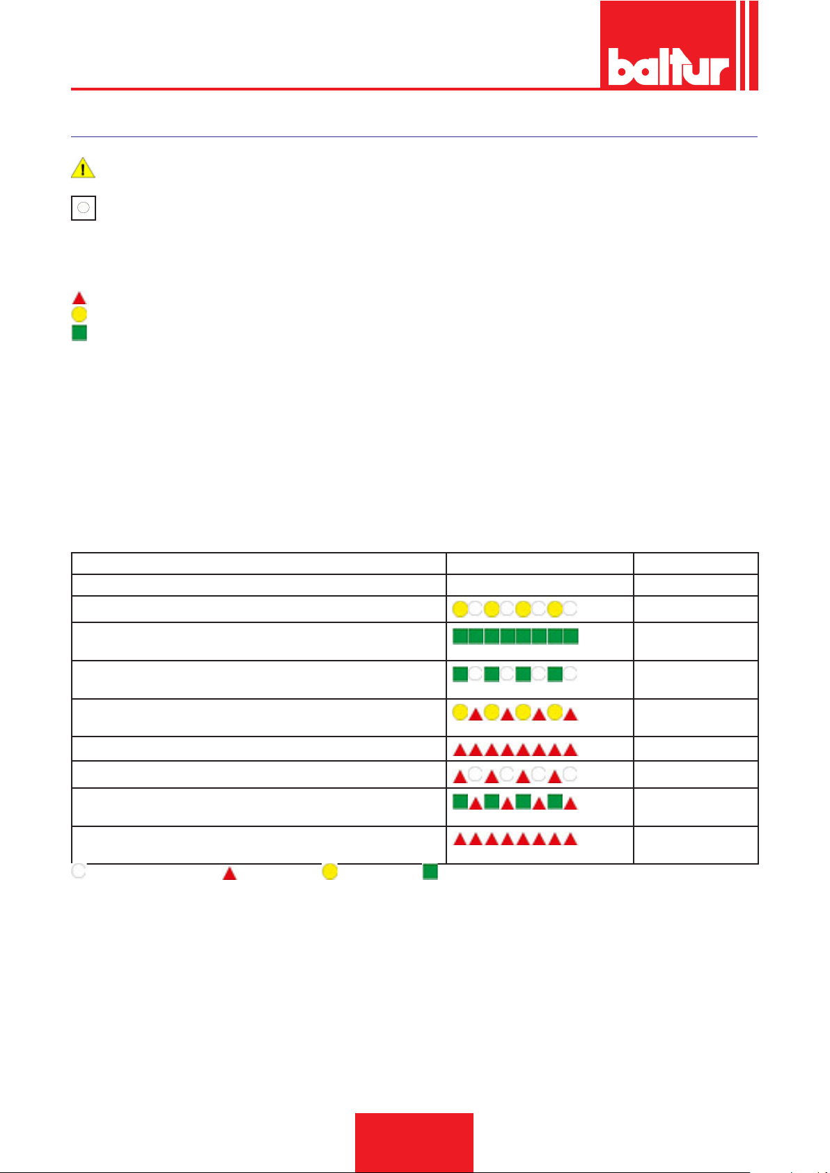
APPARECCHIATURA DI COMANDO E CONTROLLO LME 73...
per ulteriori informazioni consultare la Guida rapida dell'apparecchiatura fornita a corredo con il manuale.
Il pulsanate reset di blocco ') (pulsante info) (EK) è l'elemento operativo chiave per resettare il controllo del
bruciatore e per attivare / disattivare le funzioni diagnostiche.
La spia (LED) è l'elemento chiave indicativo per le diagnostiche visuali.
ROSSO
GIALLO
VERDE
Entrambi i pulsanti reset di blocco (EK) e la spia multicolore (LED) sono collocate nel pannello di controllo
Possibilità di due funzioni di diagnostica:
1. Diagnostica visuale: indicazione dello stato operativo oppure diagnostica della causa del blocco.
2. Diagnostica: visualizzazione e unità operativa attraverso BCI no a AZL2 ...
') diagnostica visiva: in operatività normale, i differenti stati operativi sono indicati sotto forma di codice colore, secodno la tabella dei
colori qui sotto.
INDICAZIONI DI STATO OPERATIVE
Durante l'accensione, si hanno indicazioni di stato secondo la seguente tabella:
Tabella codici colori per la spia (LED).
Condizione Sequenza colori Colori
Condizioni di attesa TW, altri stati intermedi . . . . . . . . Nessuna luce
Fase di accensione
Funzionamento corretto, intensità di corrente rilevatore amma superio-
Giallo intermittente
Verde
re al minimo ammesso
Funzionamento non corretto, intesità di corrente rilevatore amma
Verde intermittente
inferiori al minimo ammesso
Diminuzione tensione di alimentazione
Giallo e Rosso
alternati
Condizione di blocco bruciatore
Segnalazione guasto (vedere legenda colori)
Luce parassita durante l’accensione del bruciatore
Rosso
Rosso intermittente
Verde Rosso alternati
Lampeggìo veloce per diagnostica
Rosso lampeggiante
rapido
NESSUNA LUCE. ROSSO. GIALLO. VERDE.
28 / 44
0006160003_201510
Page 31
ITALIANO
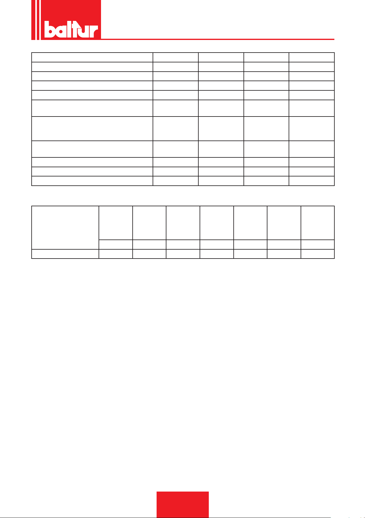
Riferimento tipologia PME73.810A2 PME73.820A2 PME73.830A2 PME73.840A2
Per utilizzo con LME73.000A • • • •
Programma gas per bruciatore con ventola • • • •
Monostadio / bistadio o modulante monostadio • • • •
Bruciatore pilota simultaneo/alternante - - • •
Modulazione mediante attuatore (controllo
• • • •
pneumatico o meccanico del rapporto gas-aria)
Comando dell’attuatore con segnale analogico
• - • -
/ segnale a 3 punti per attuatori con potenziometro
Segnale a 3 punti per attuatori senza potenzio-
- • - •
metro
Tempo programmabile in sequenza di comando • • • •
POC • • • •
Controllo di tenuta • • • •
Apparecchiatura o pro-
grammazione
Tempo di
sicurezza
Tempo di
preventila-
zione
Pre-accen-
sione
Post-accen-
sione
Tempo tra
apertura
valvola 1°
stadio e
Tempo
di corsa
apertura
serranda
Tempo
di corsa
chiusura
serranda
valvola 2°
stadio
s s s s s s s
LME73... 3 30 2 2 11 30 30
29 / 44
0006160003_201510
Page 32
ITALIANO
7101z03e0305
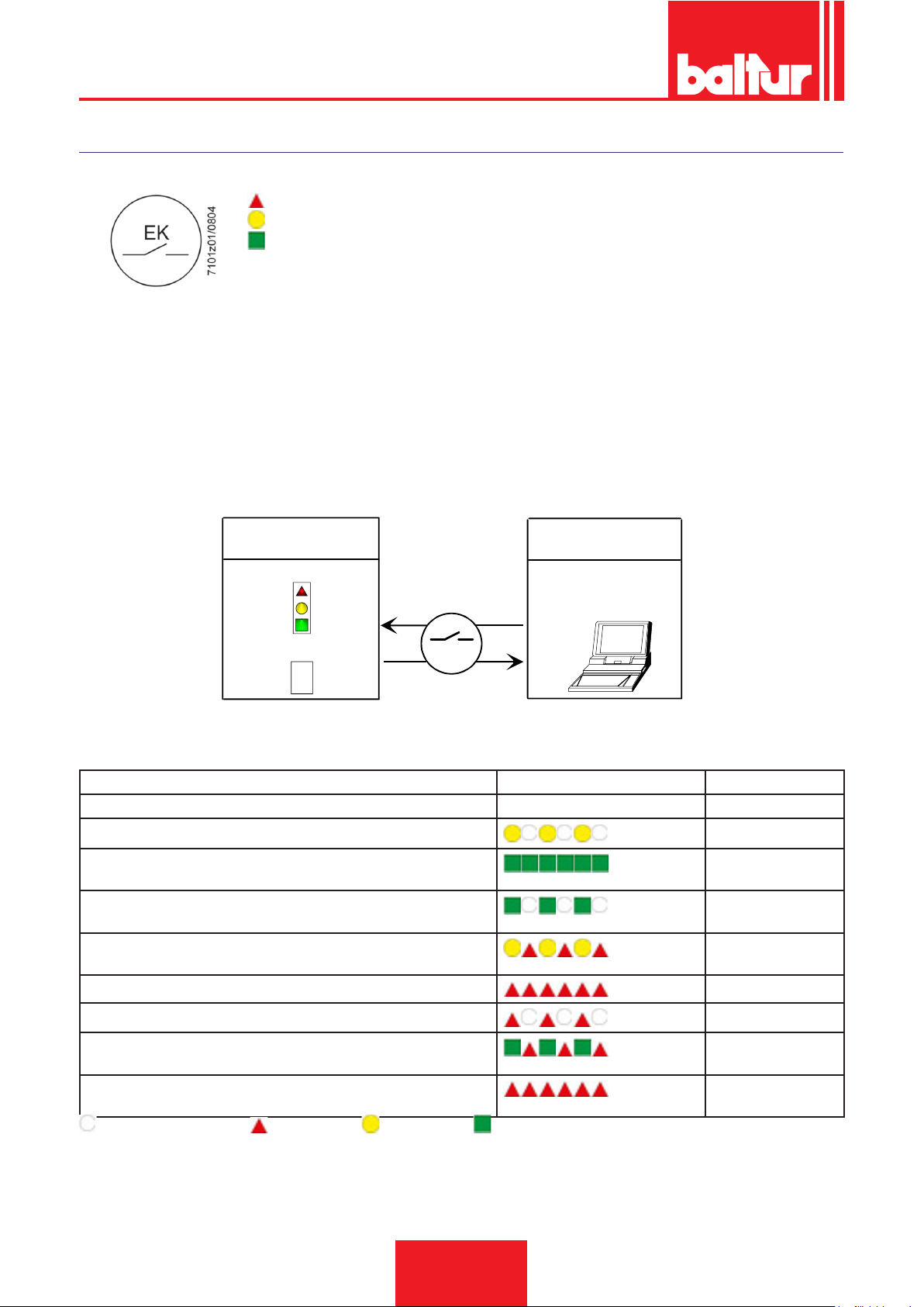
APPARECCHIATURA DI COMANDO E CONTROLLO LME...
FUNZIONAMENTO.
ROSSO
GIALLO
VERDE
Sia «LED» che «EK...» sono posizionati sotto il pulsante trasparente, premendolo si procede allo sblocco del dispositivo di comando e
controllo.
Possibilità di due funzioni di diagnostica:
1. Indicazione visiva direttamente sul pulsante di sblocco, funzionamento e diagnosi dello stato del dispositivo.
2. Diagnostica con interfaccia, in questo caso è necessario il cavo di collegamento OCI400 che può essere collegato ad un PC con
software ACS400, o ad analizzatori gas di differenti costruttori.
Indicazione visiva.
Durante il funzionamento, sul pulsante di sblocco è indicata la fase in cui il dispositivo di comando e controllo si trova, nella tabella sono
riepilogate le sequenze dei colori ed il loro signicato. Per attivare la funzione di diagnosi premere per almeno 3 secondi il pulsante di
sblocco, un lampeggio veloce di colore rosso indicherà che la funzione è attiva; analogamente per disattivare la funzione basterà premere
per almeno 3 secondi il pulsante di sblocco, (la commutazione verrà indicata con luce gialla lampeggiante).
Il pulsante di sblocco «EK...» è l’elemento principale per poter accedere a
tutte le funzioni di diagnostica (attivazione e disattivazione), oltre a sbloc-
care il dispositivo di comando e controllo.
Posizione di funzionamento
Diagnostica
Tabella codici colore
xxxxxxxx
xxxxxxxx
xxxxxxxx
xxxxxxxx
xxxxxxxx
xxxxxxxx
> 3 s
EK
Posizione di funzionamento
interfaccia PC / analizzatore
diagnostica
INDICAZIONI DELLO STATO DEL DISPOSITIVO DI COMANDO E CONTROLLO.
Condizione Sequenza colori Colori
Condizioni di attesa TW, altri stati intermedi . . . . . . . . Nessuna luce
Fase di accensione
Funzionamento corretto, intensità di corrente rilevatore amma superio-
Giallo intermittente
Verde
re al minimo ammesso
Funzionamento non corretto, intesità di corrente rilevatore amma
Verde intermittente
inferiori al minimo ammesso
Diminuzione tensione di alimentazione
Giallo e Rosso
alternati
Condizione di blocco bruciatore
Rosso
Segnalazione guasto (vedere legenda colori)
Luce parassita durante l’accensione del bruciatore
Rosso intermittente
Verde Rosso alternati
Lampeggìo veloce per diagnostica
Rosso lampeggiante
rapido
NESSUNA LUCE. ROSSO. GIALLO. VERDE.
30 / 44
0006160003_201510
Page 33
ITALIANO
E K
> 3 s
xxxxxxxx
xxxxxxxx
xxxxxxxx
xxxxxxxx
xxxxxxxx
xxxxxxxx
E K
OCI400
E K
< 3 s
7101z04e0305
R e s e t
O n
> 3 s
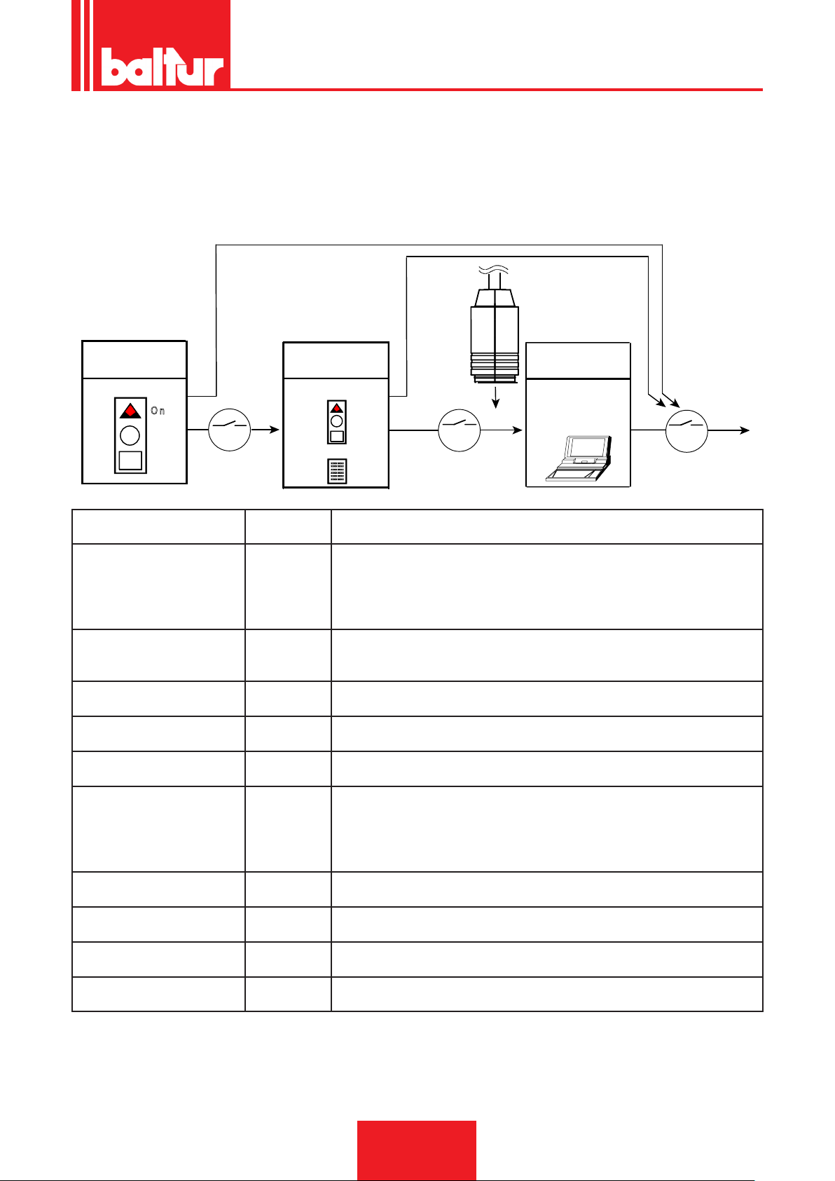
DIAGNOSI DELLE CAUSE DI MALFUNZIONAMENTO E BLOCCO.
In caso di blocco bruciatore nel pulsante di sblocco sarà ssa la luce rossa.
Premendo per più di 3 sec. la fase di diagnosi verrà attivata (luce rossa con lampeggio rapido), nella tabella sottostante viene riportato il
signicato della causa di blocco o malfunzionamento in funzione del numero di lampeggi (sempre colore rosso).
Premendo il pulsante di sblocco per almeno 3 sec. si interromperà la funzione di diagnosi.
Lo schema sotto riportato indica le operazioni da eseguire per attivare le funzioni di diagnostica anche con interfaccia di comunicazione
attraverso il cavo di collegamento "OCI400".
Posizione di
funzionamento
Posizione di
funzionamento
Indicazione visiva
Tabella codici colore
Indicazione ottica "AL" al morset-
to 10
2 lampeggi
On Assenza del segnale di amma alla ne del tempo di sicurezza <TSA>
●●
3 lampeggi
On - Malfunzionalità pressostato aria LP
●●●
4 lampeggi
On Luce estranea durante la fase di accensione
●●●●
5 lampeggi
On - Assenza segnale pressostato aria LP
●●●●●
6 lampeggi
On Non utilizzata
●●●●●●
7 lampeggi
On Assenza del segnale di amma durante funzionamento normale, ripetizione accen-
●●●●●●●
8 lampeggi
On Non utilizzata
●●●●●●●●
9 lampeggi
On Non utilizzata
●●●●●●●●●
10 lampeggi
On Problemi di cablaggio elettrico o danneggiamenti interni al dispositivo
●●●●●●●●●●
14 lampeggi
On CPI contatto non chiuso
●●●●●●●●●●●●●●
Posizione di
funzionamento
Interfaccia PC /
analizzatore
diagnostica
Possibili cause
- Malfunzionamento valvole combustibile
- Malfunzionamento rilevatore amma
- Difettosità nella taratura del bruciatore, assenza di combustibile
- Mancata accensione difettosità trasformatore di accensione
- Mancanza segnale pressostato dopo T10
- Contatto del pressostato LP incollato in posizione di riposo
- Contatto del pressostato LP incollato in posizione di lavoro
sione (limitazione nel numero delle ripetizioni dell’accensione)
- Anomalia delle valvole combustibile
- Anomalie del rilevatore amma
- Difettosità nella taratura del bruciatore
• In condizioni di diagnosi di anomalia il dispositivo rimane disattivato.
• - Il bruciatore è spento.
• - La segnalazione di allarme «AL» è sul morsetto 10 che è sotto tensione.
• Per riattivare il dispositivo e iniziare un nuovo ciclo procedere premendo per 1 sec. (< 3 sec) il pulsante di sblocco.
31 / 44
0006160003_201510
Page 34
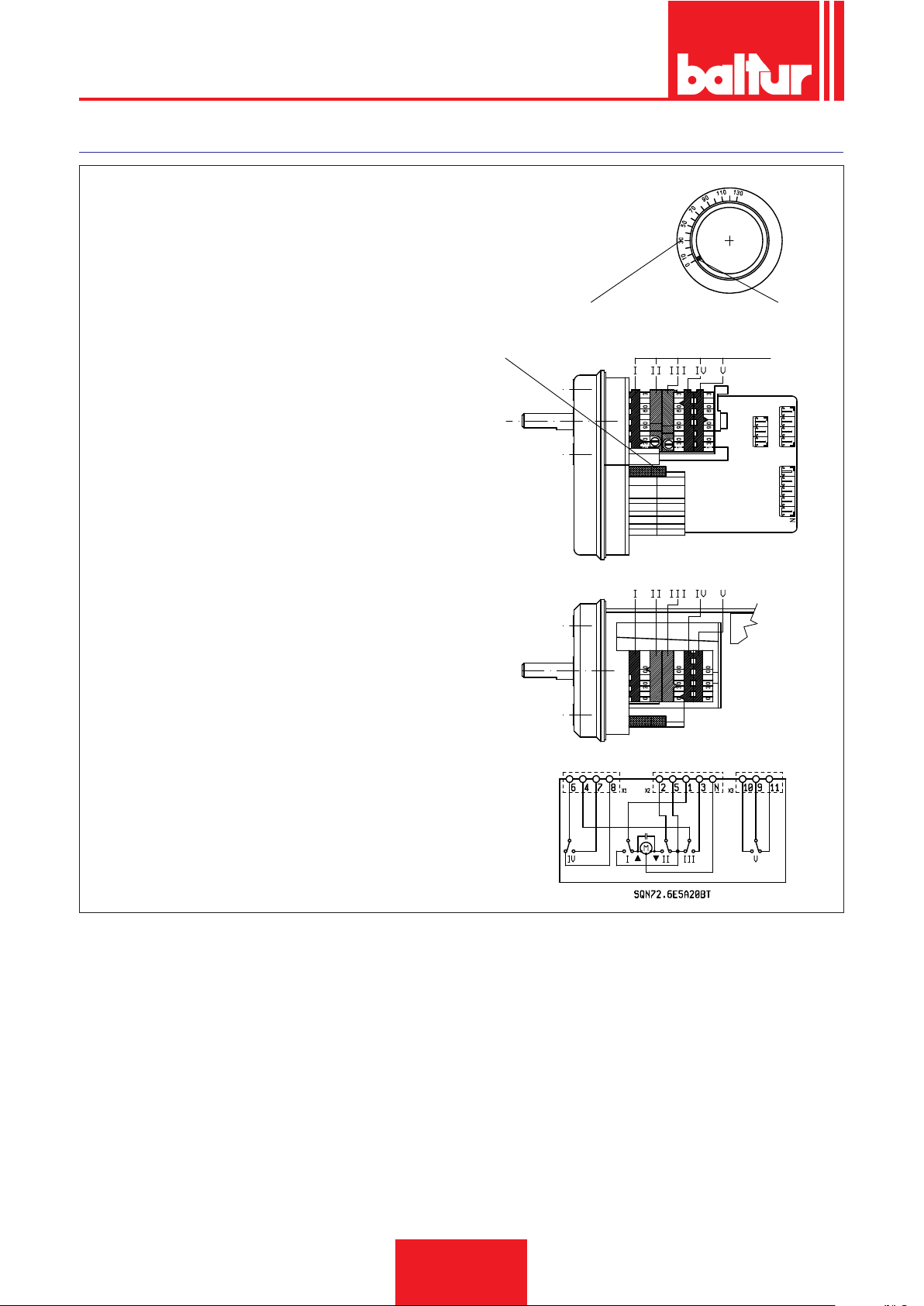
ITALIANO
REGOLAZIONE CAMME SERVOMOTORE SQN72.6E5A20BT
Per modicare la regolazione delle camme utilizzate, si agisce
sui rispettivi anelli (I - II - III....).L’indice dell’anello indica sulla
rispettiva scala di riferimento l’angolo di rotazione impostato per
ogni camma.
0002937920
A B
A Scala di riferimento.
B Indicatore di posizione .
C Perno di inserzione ed esclusione accoppiamento motore albero camme.
I Camma regolazione apertura massima aria (130°)
II Chiusura totale aria (bruciatore fermo) (0°)
III Camma regolazione aria per minima gas (30°)
IV Camma regolazione aria 1° amma gasolio (50°)
V Camma inserzione valvola 2° amma gasolio (maggiore di
camma IV) (80°)
C
D
32 / 44
0006160003_201510
Page 35

PRECISAZIONI SULL'USO DEL PROPANO
• Valutazione, indicativa, del costo di esercizio;
- 1 m3 di gas liquido in fase gassosa ha un potere calorico
inferiore, di circa 25,6 kWh
- Per ottenere 1 m3 di gas occorrono circa 2 Kg di gas liquido
che corrispondono a circa 4 litri di gas liquido.
• Disposizione di sicurezza
• Il gas propano liquido (G.P.L.) ha, in fase gassosa, un peso specico superiore a quello dell’aria (peso specico relativo all’aria
= 1,56 per il propano) e quindi non si disperde come il metano che ha un peso specico inferiore (peso specico relativo
all’aria = 0,60 per il metano), ma precipita e si spande al suolo
(come fosse un liquido). Riassumiamo di seguito i concetti che
riteniamo più importanti nell’impiego del gas propano liquido.
• L’utilizzo del gas propano liquido (G.P.L.) bruciatore e/o caldaia
può avvenire solo in locali fuori terra e attestati verso spazi liberi. Non sono ammesse installazioni che utilizzano il G.P.L. in
locali seminterrati o interrati.
• I locali dove si utilizza gas propano liquido devono avere aper-
ture di ventilazione prive di dispositivo di chiusura ricavate su
pareti esterne, rispettare le normative locali vigenti.
• Esecuzione impianto del gas propano liquido per assicura-
re un corretto funzionamento in sicurezza.
La gassicazione naturale, da batteria di bombole o serbatoio, è utilizzabile solo per impianti di piccola potenza. La capacità di erogazione in fase di gas, in funzione delle dimensioni del serbatoio e della temperatura minima esterna sono esposte, solo a titolo indicativo, nella seguente tabella.
ITALIANO
PERICOLO / ATTENZIONE
La potenza massima e minima (kW) del bruciatore, è considerata con combustibile metano che coincide approssimativamente con quella del propano.
• Controllo combustione
Per Contenere i consumi e principalmente per evitare gravi
inconvenienti, regolare la combustione impiegando gli appositi
strumenti. E’ assolutamente indispensabile accertare che la percentuale di ossido di carbonio (CO) non superi il valore massimo
ammesso dalla normativa locale vigente (impiegare l’analizzatore di combustione).
PERICOLO / ATTENZIONE
Sono esclusi dalla garanzia i bruciatori fonzionanti a gas
propano liquido (G.P.L.) in impianti dove non siano state
adottate le disposizioni sopra esposte.
Temperatu-
ra minima
Serbatoio
990 l.
Serbatoio
3000 l.
Serbatoio
5000 l.
- 15 °C - 10 °C - 5 °C - 0 °C + 5 °C
1,6 Kg/h 2,5 Kg/h 3,5 Kg/h 8 Kg/h 10 Kg/h
2,5 Kg/h 4,5 Kg/h 6,5 Kg/h 9 Kg/h 12 Kg/h
4 Kg/h 6,5 Kg/h
11,5
Kg/h
16 Kg/h 21 Kg/h
33 / 44
0006160003_201510
Page 36
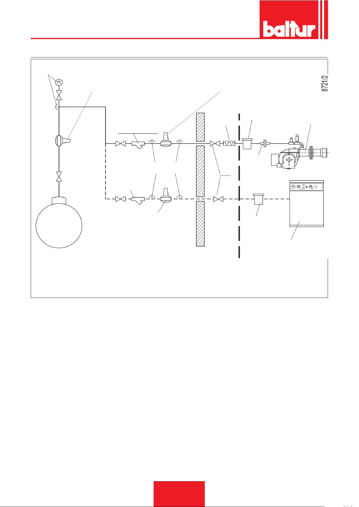
ITALIANO
SCHEMA DI PRINCIPIO PER RIDUZIONE PRESSIONE G.P.L. A DUE STADI PER BRUCIATORE OPPURE CALDAIA
Manometro e presa di
pressione
Riduttore di 1° salto
Uscita ~ 1,5 bar
Portata ~ il doppio del massimo richiesto
dall’utilizzatore
Riduttore di 2° salto
Uscita ~ 30 mbar
Portata ~ il doppio del massimo richiesto
dall’utilizzatore
Serbatoio G.P.L.
Filtro a Y
Presa di pressione
Filtro a Y
Riduttore di 2° salto
Uscita ~ 30 mbar
Portata ~ il doppio del massimo richiesto
dall’utilizzatore
A CURA DELL’INSTALLATORE
Giunto
antivibrante
Filtro
Raccordo
Rubinetto a sfera
Filtro
Caldaia a pavimento o murale
FORNITO DAL COSTRUTTORE
Bruciatore
34 / 44
0006160003_201510
Page 37
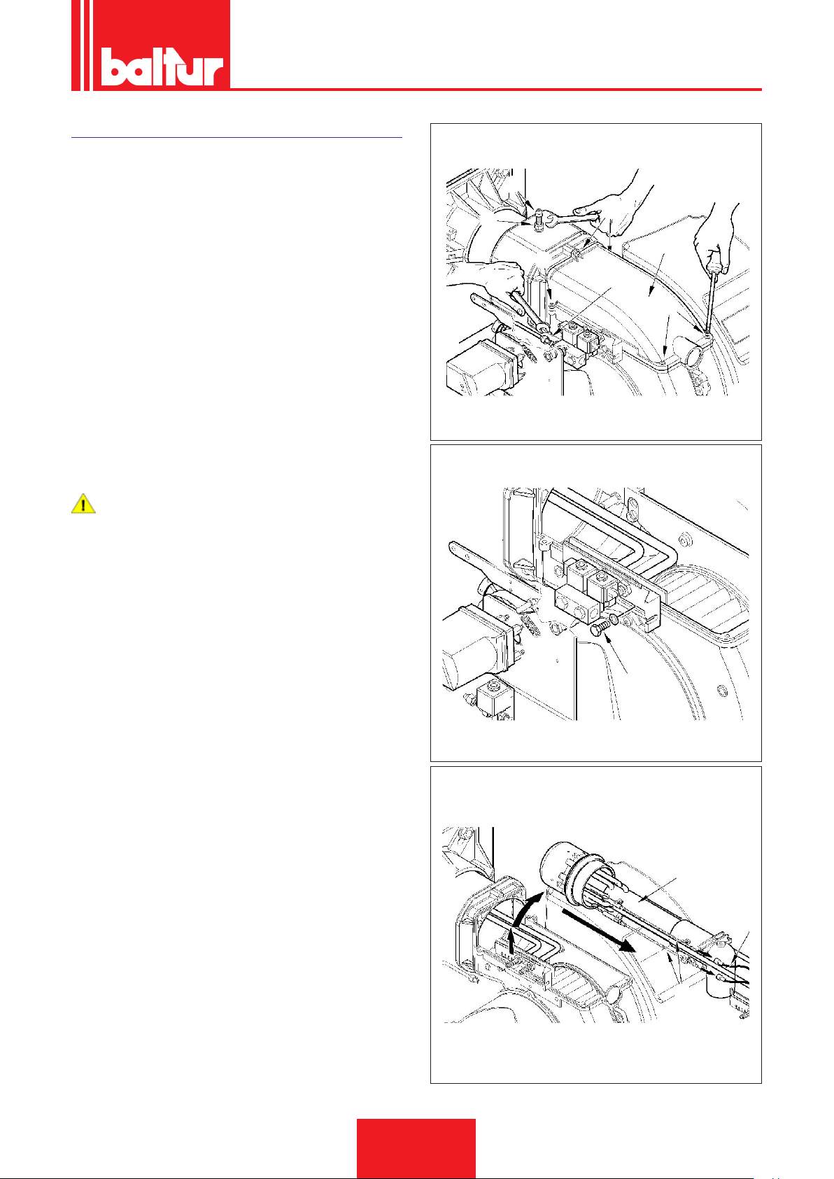
MANUTENZIONE
0002937470
Effettuare almeno una volta all’anno e comunque in conformità
alle norme vigenti, l’analisi dei gas di scarico della combustione
vericando la correttezza dei valori di emissioni.
Al termine della stagione di riscaldamento, eseguire le seguenti
operazioni:
• Pulire le serrande aria, il pressostato aria con presa di pressione ed il relativo tubo se presenti.
• Vericare lo stato degli elettrodi. Se necessario sostituirli.
• Pulire la fotocellula. Se necessario sostituirla.
• Far pulire la caldaia ed il camino da personale specializzato in
fumisteria, una caldaia pulita ha maggior rendimento, durata e
silenziosità.
• Controllare che il ltro del combustibile sia pulito. Se necessario
sostituirlo.
• Vericare che tutti i componenti della testa di combustione siano in buono stato, non deformati e privi di impurità o depositi
derivanti dall'ambiente di installazione e/o da una cattiva combustione.
• Effettuare l’analisi dei gas di scarico della combustione veri-
cando la correttezza dei valori di emissioni.
PERICOLO / ATTENZIONE
All'atto della chiusura del bruciatore, tirare delicatamente
verso il quadro elettrico, mettendoli in leggera tensione,
i due cavi di accensione, quindi sistemarli nelle apposite
sedi sulla chiocciola. Questo eviterà che i due cavi vengano danneggiati dalla ventola durante il funzionamento del
bruciatore.
Nel caso si renda necessaria la pulizia della testa di combustione
occorre smontarla procedendo nel seguente modo:
• Scollegare dal coperchio superiore del bruciatore la fotocellula
e il tubino pressostato aria.
• Scollegare il tubino gasolio (24) dal relativo raccordo (attenzione al goccilamento).
• Svitare le viti 5 (6) e rimuovere il coperchio (11) .
• Dopo aver allentato il dado (9) rimuovere la vite di bloccaggio
(32) del gruppo miscelatore.
• Togliere la vite (16) e la relativa rondella posta all’esterno della
chiocciola del bruciatore.
• Sollevare leggermente il gruppo di miscelazione (17), quindi
estrarre completamente il gruppo stesso nella direzione indicata dalla freccia, dopo aver slato i cavi di accensione (10) dai
rispettivi elettrodi.
• Completate le operazioni di manutenzione procedere con il
montaggio del gruppo di miscelazione seguendo a ritroso il per-
corso sopra descritto e dopo aver vericato la corretta posizione degli elettrodi di accensione e del disco amma.
9
0002937480
ITALIANO
32
6
11
6
24
6
16
17
35 / 44
0006160003_201510
Page 38
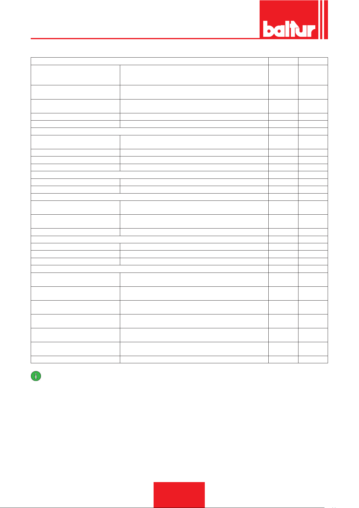
ITALIANO
TEMPI DI MANUTENZIONE
TESTA DI COMBUSTIONE GAS GASOLIO
CONTROLLO VISIVO, INTERGITA CERAMICHE. SMERIGLIATURA
ELETTRODI
DISCO FIAMMA
COMPONENTI TESTA COMBUSTIONE
UGELLI COMBUSTIBILE LIQUIDO SOSTITUZIONE N.A. ANNUO
GUARNIZIONE ISOLANTE CONTROLLO VISIVO TENUTA ED EVENTUALE SOSTITUZIONE ANNUO ANNUO
CUSCINETTI SERRANDA ARIA
VENTOLA ARIA PULIZIA ANNO ANNO
PRESSOSTATO ARIA PULIZIA ANNO ANNO
PRESA E CONDOTTI PRESSIONE ARIA PULIZIA ANNO ANNO
SENSORE FIAMMA PULIZIA ANNO ANNO
PRESSOSTATO GAS VERIFICA FUNZIONALE ANNO ANNO
MOTORI ELETTRICI (CUSCINETTI/VEN-
TOLA RAFFREDDAMENTO)
LEVE/TIRANTI/SNODI SFERICI (GIOCHI/
LUBRIFICAZIONE)
TUBI FLESSIBILI SOSTITUZIONE N.A. 5 ANNI
FILTRO POMPA PULIZIA ANNO ANNO
FILTRO DI LINEA PULIZIA / SOSTITUZIONE (CARTUCCIA RICAMBIO?) ANNO ANNO
FILTRO GAS SOSTITUIRE ELEMENTO FILTRANTE ANNO ANNO
CONTROLLO CO
CONTROLLO CO2
CONTROLLO INDICE DI FUMO BACHA-
RACH
CONTROLLO NOX
CONTROLLO CORRENTE DI IONIZZA-
ZIONE
CONTROLLO TEMPERATURA FUMI
REGOLATORE PRESSIONE GAS RILIEVO PRESSIONE ALL'AVVIAMENTO ANNO N.A.
ESTREMITA, VERIFICARE DISTANZA, VERIFICARE CONNESSIONE
ELETTRICA.
CONTROLLO VISIVO INTEGRITA EVENTUALI DEFORMAZIONI,
PULIZIA,
CONTROLLO VISIVO INTEGRITA EVENTUALI DEFORMAZIONI,
PULIZIA,
LINEA ARIA GAS GASOLIO
INGRASSAGGIO, (N.B. mettere solo su bruciatori con cuscinetti da
ingrassare)
COMPONENTI DI SICUREZZA GAS GASOLIO
COMPONENTI VARI GAS GASOLIO
PULIZIA, (vedere se esistono indicazioni del fornitore) ANNO ANNO
CONTROLLO EVENTUALI GIOCHI ANNO ANNO
LINEA COMBUSTIBILE GAS GASOLIO
PARAMETRI DI COMBUSTIONE GAS GASOLIO
CONFRONTO CON VALORI REGISTRATI ALL'AVVIAMENTO DEL'IM-
PIANTO
CONFRONTO CON VALORI REGISTRATI ALL'AVVIAMENTO DEL'IM-
PIANTO
CONFRONTO CON VALORI REGISTRATI ALL'AVVIAMENTO DEL'IM-
PIANTO
CONFRONTO CON VALORI REGISTRATI ALL'AVVIAMENTO DEL'IM-
PIANTO
CONFRONTO CON VALORI REGISTRATI ALL'AVVIAMENTO DEL'IM-
PIANTO
CONFRONTO CON VALORI REGISTRATI ALL'AVVIAMENTO DEL'IM-
PIANTO
ANNUO ANNUO
ANNUO ANNUO
ANNUO ANNUO
6 MESI 6 MESI
ANNO ANNO
ANNO ANNO
ANNO ANNO
ANNO ANNO
ANNO ANNO
ANNO ANNO
IMPORTANTE
Per utilizzi gravosi o con combustibili particolari, gli intervalli tra una manutenzione e la successiva, dovranno essere ridotti ade-
guandoli alle effettive condizioni di impiego secondo le indicazioni del manutentore.
36 / 44
0006160003_201510
Page 39

ITALIANO
TABELLA PORTATA UGELLI
Ugello Pressione pompa Ugello
7 8 9 10 11 12 13 14 15 16 17 18 19 20 21
G.P.H. Portata all'uscita dell'ugello G.P.H.
0,40 1,27 1,36 1,44 1,52 1,59 1,67 1,73 1,80 1,86 1,92 1,98 2,04 2,10 2,15 2 0,40
0,50 1,59 1,70 1,80 1,90 1,99 2,08 2,17 2,25 2,33 2,40 2,48 2,55 2,62 2,69 2,75 0,50
0,60 1,91 2,04 2,16 2,28 2,39 2,50 2,60 2,70 2,79 2,88 2,97 3,06 3,14 3,22 3,30 0,60
0,65 2,07 2,21 2,34 2,47 2,59 2,71 2,82 2,92 3,03 3,12 3,22 3,31 3,41 3,49 3,58 0,65
0,75 2,38 2,55 2,70 2,85 2,99 3,12 3,25 3,37 3,49 3,61 3,72 3,82 3,93 4,03 4,13 0,75
0,85 2,70 2,89 3,06 3,23 3,39 3,54 3,68 3,82 3,96 4,09 4,21 4,33 4,45 4,57 4,68 0,85
1,00 3,18 3,40 3,61 3,80 3,99 4,16 4,33 4,50 4,65 4,81 4,96 5,10 5,24 5,37 5,51 1,00
1,10 3,50 3,74 3,97 4,18 4,38 4,58 4,77 4,95 5,12 5,29 5,45 5,61 5,76 5,91 6,06 1,10
1,20 3,82 4,08 4,33 4,56 4,78 5,00 5,20 5,40 5,59 5,77 5,95 6,12 6,29 6,45 6,61 1,20
1,25 3,97 4,25 4,50 4,75 5,00 5,20 5,40 5,60 5,80 6,00 6,20 6,35 6,55 6,70 6,85 1,25
1,35 4,29 4,59 4,87 5,13 5,38 5,62 5,85 6,07 6,28 6,49 6,69 6,88 7,07 7,26 7,44 1,35
1,50 4,77 5,10 5,41 5,70 5,90 6,24 6,50 6,75 6,98 7,21 7,43 7,65 7,86 8,06 8,26 1,50
1,65 5,25 5,61 5,95 6,27 6,58 6,87 7,15 7,42 7,68 7,93 8,18 8,41 8,64 8,87 9,09 1,65
1,75 5,56 5,95 6,31 6,65 6,98 7,29 7,58 7,87 8,15 8,41 8,67 8,92 9,17 9,41 9,64 1,75
2,00 6,30 6,80 7,21 7,60 7,97 8,33 8,67 8,99 9,31 9,61 9,91 10,20 10,48 10,75 11,01 2,00
2,25 7,15 7,65 8,15 8,55 8,97 9,37 9,75 10,12 10,47, 10,85 11,15 11,47 11,79 12,09 12,39 2,25
2,50 7,95 8,50 9,01 9,50 9,97 10,41 10,83 11,24 11,64 12,02 12,39 12,75 13,10 13,44 13,77 2,50
3,00 9,54 10,20 10,82 11,40 11,96 12,49 13,00 13,49 13,96 14,02 14,87 15,30 15,72 16,12 16,52 3,00
3,50 11,13 11,90 12,62 13,30 13,95 14,57 15,17 15,74 16,29 16,83 17,34 17,85 18,34 18,81 19,28 3,50
4,00 12,72 13,60 14,42 15,20 15,94 16,65 17,33 17,99 18,62 19,23 19,82 20,40 20,95 21,50 22,03 4,00
4,50 14,31 15,30 16,22 17,10 17,94 18,73 19,50 20,24 20,95 21,63 22,30 22,95 23,57 24,19 24,78 4,50
5,00 15,90 17,00 18,03 19,00 19,93 20,82 21,67 22,48 23,27 24,04 24,78 25,49 26,19 26,87 27,54 5,00
5,5 17,49 18,70 19,83 20,90
6,00 19,00 20,40 21,63 22,80 23,92 24,98 26,00 26,98 27,93 28,84 29,73 30,59 31,43 32,25 33,04 6,00
6,50 20,67 22,10 23,44 23,70 25,91 27,06 28,17 29,23 30,26 31,25 32,21 33,14 34,05 34,94 35,80 6,50
7,00 22,26 23,79 25,24 26,60 27,60 29,14 30,33 31,48 32,58 33,65 34,69 35,69 36,67 37,62 38,55 7,00
7,50 23,85 25,49 27,04 28,50 29,90 31,22 32,50 33,73 3491 36,05 37,16 38,24 39,29 40,31 41,31 7,50
8,30 26,39 28,21 29,93 31,54 33,08 34,55 35,97 37,32 38,63 39,90 41,13 42,32 43,48 44,61 45,71 8,30
9,50 30,21 32,29 34,25 36,10 37,87 39,55 41,17 42,72 44,22 45,67 47,07 48,44 48,77 51,06 52,32 9,5
10,50 33,39 35,69 37,86 40,06 41,73 43,74 45,41 47,20 48,90 50,50 52,00 53,50 55,00 56,40 57,80 10,50
12,00 38,20 40,80 43,30 45,60 47,80 50,00 52,00 54,00 55,90 57,70 59,50 61,20 62,90 64,50 66,10 12,00
13,80 43,90 46,90 49,80 52,40 55,00 57,50 59,80 62,10 64,20 66,30 68,40 70,40 72,30 74,30 76,00 13,80
15,30 48,60 52,00 55,20 58,10 61,00 63,70 66,30 68,80 71,10 73,60 75,80 78,00 80,20 82,20 84,30 15,30
17,50 55,60 59,50 63,10 66,50 69,80 72,90 75,80 78,70 81,50 84,10 86,70 89,20 91,70 94,10 96,40 17,50
19,50 62,00 66,30 70,30 74,10 77,70 81,20 84,50 87,70 90,80 93,70 96,60 99,40
21,50 68,40 73,10 77,50 81,70 85,70 89,50 93,20 96,70
24,00 76,30 81,60 86,50 91,20 95,70 99,90
28,00 89,00 95,20
30,00 95,40
101,00 106,40
102,00 108,20
21,92 22,90 23,83 24,73 25,6 26,44 27,25 28,04 28,81 29,56 30,29 5,5
102,20 104,80 107,40
111,60
114,00 119,60
100,10 103,40 106,50 109,60
104,00 107,90
116,60
121,30 125,90 130,30 134,60 138,70
124,90 130,00 134,90 139,90 144,20 148,70 153,00 157,20
11,70
115,40 118,90
122,40
142,80
112,60
115,60
125,70
129,00 132,20
146,70 150,50
161,20
118,40
154,20
165,20
19,50
21,50
24,00
28,00
30,00
1 mbar = 10 mmCA = 100 Pa
1 kW = 860 kcal
Densità gasolio =0,820 / 0,830 PCI = 10150
Densità olio combustibile (3,5° E) = 0,940 PCI = 9700
Densità olio combustibile denso (7,9° E) = 0,970/0,980 PCI = 9650
PCI Potere Calorico Inferiore
37 / 44
0006160003_201510
Page 40

ITALIANO
ISTRUZIONI PER L'ACCERTAMENTO DELLE CAUSE DI IRREGOLARITÀ NEL FUNZIONA-
MENTO E LA LORO ELIMINAZIONE
IRREGOLARITÁ
Bruciatore che non si avvia.(L'apparecchiatura non
effettua il programma di accensione).
Fiamma difettosa con presenza
di faville.
POSSIBILE CAUSA
1 Termostati (caldaia o ambiente) o
pressostati, aperti.
2 Fotoresistenza in corto circuito.
3 Mancanza di tensione in linea, inter-
ruttore generale aperto, interruttore
del contatore scattato o mancanza di
tensione in linea.
4 La linea dei termostati non è stata
eseguita secondo schema o qualche
termostato è rimasto aperto.
5 Guasto interno all’apparecchiatura.
1 Pressione di polverizzazione troppo
bassa.
2 Eccesso di aria comburente.
3 Ugello inefciente perché sporco o
logoro.
4 Presenza di acqua nel combustibile.
RIMEDIO
1 Alzare il valore dei termostati oppure
attendere che si chiudano i contatti per
diminuzione naturale della temperatura
o pressione.
2 Sostituirla.
3 Chiudere gli interruttori o attendere il
ritorno della tensione.
4 Controllare i collegamenti e i termosta-
ti.
5 Sostituirla.
1 Ripristinarla al valore previsto.
2 Diminuire l’aria comburente
3 Pulire o sostituire.
4 Scaricare l'acqua dalla cisterna serven-
dosi di una pompa adatta. Non usare
mai per questo lavoro la pompa del
bruciatore.
Fiamma non ben conformata
con fumo e fuliggine.
Fiamma difettosa, pulsante, o
sfuggente dalla bocca di combustione.
1 Insufcienza di aria comburente.
2 Ugello inefciente perché sporco o
logoro.
3 Ugello di portata insufciente rispetto
al volume della camera di combu-
stione.
4 Camera di combustione di forma non
adatta o troppo piccola.
5 Rivestimento refrattario non adatto
(riduce eccessivamente lo spazio
della amma).
6 Condotti della caldaia o camino
ostruiti.
7 Pressione di polverizzazione bassa.
1 Tiraggio eccessivo, solo in caso di
un aspiratore al camino.
2 Ugello inefciente perché sporco o
logoro.
3 Presenza di acqua nel combustibile.
4 Disco amma sporco.
5 Eccesso di aria comburente.
6 Passaggio d’aria tra disco amma e
diffusore eccessivamente chiuso.
1 Aumentare l’aria comburente.
2 Pulire oppure sostituire.
3 Diminuire la portata di gasolio in rappor-
to alla camera (ovviamentela potenza
termica esagerata risulterà inferiore a
quella necessaria) o sostituire la calda-
ia.
4 Aumentare la portata dell’ugello sosti-
tuendolo.
5 Modicarlo attenendosi alle istruzioni
del costruttore della caldaia.
6 Provvedere alla loro pulizia.
7 Riportarla al valore prescritto.
1 Adeguare la velocità di aspirazione
modicando i diametri delle pulegge.
2 Pulire oppure sostituire.
3 Scaricare l'acqua dalla cisterna serven-
dosi di una pompa adatta. Non usare
mai per questo lavoro la pompa del
bruciatore.
4 Pulire.
5 Ridurre l'aria comburente.
6 Correggere la posizione del dispositivo
di regolazione della testa di combustio-
ne.
38 / 44
0006160003_201510
Page 41

ITALIANO
IRREGOLARITÁ
Corrosioni interne nella caldaia.
Fuliggine allo sbocco del camino.
POSSIBILE CAUSA
1 Temperatura di esercizio della
caldaia troppo bassa (inferiore al
punto di rugiada).
2 Temperatura dei fumi troppo bassa,
indicativamente al di sotto dei 130°
C per gasolio.
1 Eccessivo raffreddamento dei fumi
(indicativamente al di sotto dei 130°
C) in canna fumaria, per camino
esterno non sufcientemente
coibentato, oppure per inltrazioni
di aria fredda.
RIMEDIO
1 Aumentare la temperatura di esercizio.
2 Aumentare la portata di gasolio se la
caldaia lo consente.
1 Migliorare l’isolamento ed eliminare
ogni apertura che possa consentire
l’ingresso di aria fredda al camino.
L’apparecchio va in blocco (lampada rossa accesa) il guasto è cir-
coscritto al dispositivo di controllo
amma.
L’apparecchio va in blocco spruzzando combustibile liquido senza
il vericarsi della amma (lampada
rossa accesa).
Il guasto è circoscritto al dispositivo di accensione, ammesso che il
combustibile sia non inquinato da
acqua o altro e sufcientemente
polverizzato.
L’apparecchio va in blocco, il gas
esce, ma la amma non è presente (lampada rossa accesa). Guasto
circoscritto al circuito di accensione.
1 Fotoresistenza interrotta o sporca
di fumo.
2 Tiraggio insufciente.
3 Circuito del rilevatore amma inter-
rotto nell’apparecchiatura.
4 Disco amma o diffusore sporchi.
1 Interruzione nel circuito di accen-
sione.
2 I cavetti del trasformatore di accen-
sione scaricano a massa.
3 I cavetti del trasformatore di accen-
sione non sono ben collegati.
4 Trasformatore d’accensione guasto.
5 Le punte degli elettrodi non sono
alla giusta distanza.
6 Gli elettrodi scaricano a massa per-
ché sporchi o per isolante incrinato;
controllare anche i morsetti di s-
saggio degli isolantori di porcellana.
1 Pulire o sostituire.
2 Controllare tutti i passaggi dei fumi
nella caldaia e nel camino.
3 Sostituire l’apparecchiatura.
4 Pulire.
1 Vericare tutto il circuito.
2 Sostituire.
3 Ripristinare il collegamento.
4 Sostituire.
5 Riportare nella posizione prescritta.
6 Pulire, se necessario, sostituirli.
39 / 44
0006160003_201510
Page 42

ITALIANO
IRREGOLARITÁ
L’apparecchio va in blocco spruzzando combustibile liquido senza il
vericarsi della amma. (Lampada
rossa accesa).
POSSIBILE CAUSA
1 La pressione della pompa non è
regolare.
2 Presenza di acqua nel combustibi-
le.
3 Eccesso di aria comburente.
4 Passaggio d'aria tra disco amma e
diffusore eccessivamente chiuso.
5 Ugello logoro o sporco.
RIMEDIO
1 Regolare.
2 Scaricare l'acqua dalla cisterna
servendosi di una pompa adatta. Non
usare mai per questo lavoro la pompa
del bruciatore.
3 Diminuire l’aria comburente.
4 Correggere la posizione di regolazione
della testa di combustione.
5 Pulire o sostituire.
L’apparecchio và in blocco, il gas
esce, ma la amma non è presente
(lampada rossa accesa).
Pompa del bruciatore rumorosa.
1 Rapporto aria - gas non corretto.
2 La tubazione del gas non è stata
adeguatamento sfogata dell’aria
alla prima accensione.
3 La pressione del gas è insufciente
o eccessiva.
4 Passaggio aria tra disco amma e
diffusore troppo chiuso.
1 Tubazione di diametro troppo picco-
lo.
2 Inltrazioni d’aria nei tubi.
3 Filtro combustibile sporco.
4 Distanza e/o dislivello negativo o
eccessivo fra cisterna e bruciatore,
oppure molte perdite accidentali
(curve, gomiti, strozzature ecc..)
5 Tubi essibili deteriorati.
1 Correggere il rapporto aria - gas.
2 Sfogare ulteriormente con le dovute
cautele, la tubazione del gas.
3 Vericare il valore della pressione gas
al momento dell’accensione (usare
possibilmente un manometro ad
acqua).
4 Adeguare l’apertura disco amma -
diffusore.
1 Sostituirla attenendosi alle relative
istruzioni.
2 Vericare ed eliminare tali inltrazioni.
3 Smontare e lavare.
4 Retticare l’intero sviluppo del tubo di
aspirazione riducendo così la distan-
za.
5 Sostituire.
40 / 44
0006160003_201510
Page 43
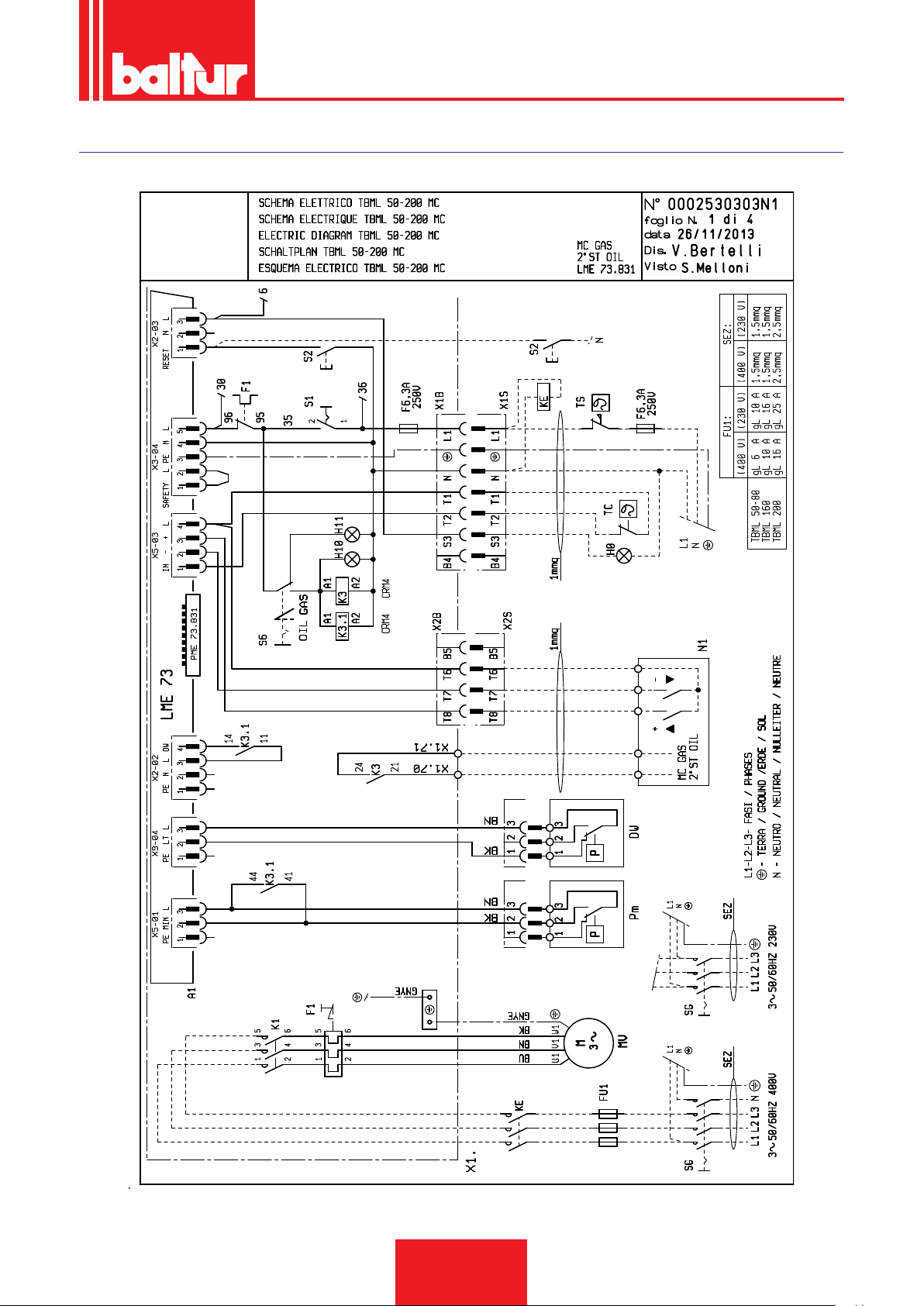
SCHEMI ELETTRICI
ITALIANO
41 / 44
0006160003_201510
Page 44
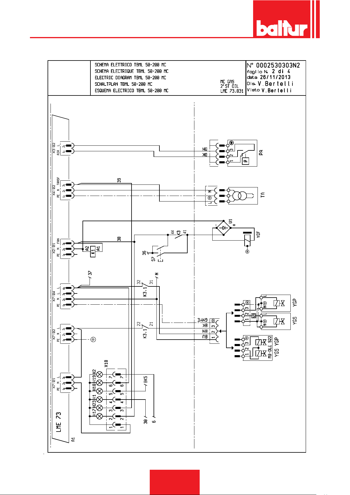
ITALIANO
42 / 44
0006160003_201510
Page 45
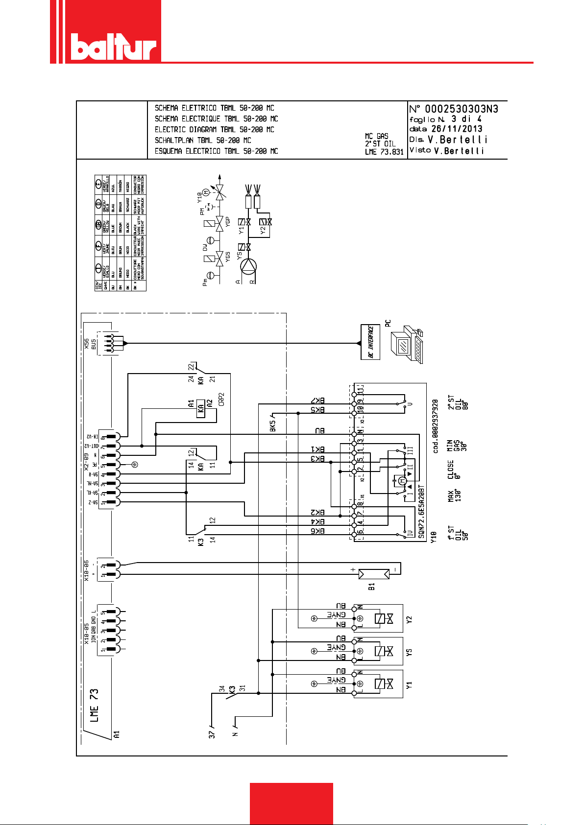
ITALIANO
43 / 44
0006160003_201510
Page 46

ITALIANO
A1 APPARECCHIATURA
B1 FOTORESISTENZA / ELETTRODO DI IONIZZAZIONE /
FOTOCELLULA UV
DW PRESSOSTATO CONTROLLO TENUTA VALVOLE
F1 RELE’ TERMICO
FU1÷4 FUSIBILI
H0 SPIA BLOCCO ESTERNA / LAMPADA FUNZIONAMEN-
TO RESISTENZE AUSILIARIE
H1 SPIA DI FUNZIONAMENTO
H2 “SPIA DI BLOCCO“
H10 “SPIA FUNZIONAMENTO OLIO“
H11 “SPIA FUNZIONAMENTO GAS”
H17 SPIA FUNZIONAMENTO VENTILATORE
H18 “SPIA FUNZIONAMENTO 2° STADIO“
H19 SPIA FUNZIONAMENTO VALVOLE PRINCIPALI
H23 SPIA FUNZIONAMENTO TRASFORMATORE
K1 CONTATTORE MOTORE VENTOLA
K3 “RELÉ AUSILIARIO MOTORINO CICLICO“
K7.1 KA / KB RELE’ AUSILIARIO
KE CONTATTORE ESTERNO
MV MOTORE VENTOLA
N1 “REGOLATORE ELETTRONICO“
PA PRESSOSTATO ARIA
Pm “PRESSOSTATO DI MINIMA“
S1 INTERRUTTORE MARCIA ARRESTO
S2 PULSANTE SBLOCCO
S6 SELETTORE COMBUSTIBILE
S7 PULSANTE CARICAMENTO SERBATOIO / IMPIANTO
SG INTERRUTTORE GENERALE
TA TRASFORMATORE D’ACCENSIONE
TC TERMOSTATO CALDAIA
TS TERMOSTATO DI SICUREZZA
U1 PONTE RADDRIZZATORE
X1B/S CONNETTORE ALIMENTAZIONE
X2B/S CONNETTORE 2° STADIO
X18 CONNETTORE SINOTTICO
Y1/Y2 ELETTROVALVOLE 1° / 2° STADIO
YS ELETTROVALVOLA DI SICUREZZA
Y10 SERVOMOTORE ARIA
YEF ELETTROFRIZIONE
YGP ELETTROVALVOLA GAS PRINCIPALE
YGS ELETTROVALVOLA GAS SICUREZZA
44 / 44
0006160003_201510
Page 47

ENGLISH
ENGLISH
INDEX
Instructions for use in safe conditions ..............................................................................................................................................pag 4
Technical specications .................................................................................................................................................................... pag 7
Supplied material........................................................................................................................................................................pag 8
Burner identication plate ........................................................................................................................................................... pag 8
First start up recording data .......................................................................................................................................................pag 8
Operating range .........................................................................................................................................................................pag 9
Overall dimensions ................................................................................................................................................................... pag 10
Component description ............................................................................................................................................................ pag 11
Electrical panel ......................................................................................................................................................................... pag 11
Burner connection to the boiler .......................................................................................................................................................pag 12
Gas supply line ......................................................................................................................................................................... pag 13
Gas burner schematic diagram ................................................................................................................................................ pag 13
Pipeline dimension diagrams ...................................................................................................................................................pag 14
Electrical connections ..................................................................................................................................................................... pag 15
Diesel supply line .....................................................................................................................................................................pag 17
Auxiliary pump .......................................................................................................................................................................... pag 17
Description of operation with liquid fuel .......................................................................................................................................... pag 19
First pipeline lling up ..................................................................................................................................................................... pag 20
Ignition and adjustment with liquid fuel ........................................................................................................................................... pag 21
Pump parts ..................................................................................................................................................................................... pag 23
Operation description with gaseous fuel .........................................................................................................................................pag 24
Modulation operation description .............................................................................................................................................pag 24
Natural gas ignition and regulation ................................................................................................................................................. pag 25
UV photocell ............................................................................................................................................................................. pag 26
Controls .................................................................................................................................................................................... pag 27
Air regulation on the combustion head ..................................................................................................................................... pag 27
Diagram for the regulation of the electrode disk distance ........................................................................................................ pag 28
LME 73...Control box ...................................................................................................................................................................... pag 29
Control and command equipment LME... ....................................................................................................................................... pag 31
Servomotor cams adjustment SQN72.6E5A20BT ..........................................................................................................................pag 33
Specications for propane use ....................................................................................................................................................... pag 34
Diagram illustrating the principle of L.P.G. pressure reduction in two stages for burner or boiler ............................................pag 35
Maintenance ................................................................................................................................................................................... pag 36
Maintenance time ..................................................................................................................................................................... pag 37
nozzle ow rate table ...................................................................................................................................................................... pag 38
Troubleshooting instructions ...........................................................................................................................................................pag 39
Wiring diagrams ..............................................................................................................................................................................pag 42
1 / 44
0006160003_201510
Page 48

DECLARATION OF CONFORMITY
CE0085:
DVGW CERT GmbH, Josef-Wirmer Strasse 1-3-53123 Bonn (D)
We hereby declare under our own responsibility, that our blown air burners red by gas and dual fuel, series:
BPM...; BGN…; BTG…; TBML...; Comist…; GI…; GI…Mist; Minicomist…; Sparkgas...; TBG..; IB..; TBR...
(Variant: … LX, for low NOx emissions; -V for inverter, FGR for fume external recirculation)
respect the minimal regulations of the European Directives and Regulations:
• 2009/142/CE - (UE) 2016/426 (D.A.G.) (R.A.G.)
• 2014/30/CE (C.E.M.)
• 2014/35/CE (D.B.T.)
• 2006/42/CE (D.M.)
and have been designed and tested in accordance with the European Standards:
• prEN 676 2008 (gas and dual fuel, gas side)
• prEN 267:2008 (dual fuel, diesel side)
• EN 60335-1 (2012-01) + EC (2014-01).
• EN 60335-2-102
• EN 60204-1
Cento, 15 Marzo 2018
Valid from: 21/04/2018
to: 21/04/2019
Managing Director
Dr. Riccardo Fava
Director of Research & Development
Ing. Paolo Bolognin
1 / 1
Page 49

ENGLISH
INSTRUCTIONS FOR USE IN SAFE CONDITIONS
PURPOSE OF THE MANUAL
The manual purpose is to contribute to the safe use of the product,
indicating the conduct and behaviour required to prevent alterations to the safety features of the apparatus which could derive
from incorrect installation or incorrect, unauthorised or unreasonable uses.
The manufacturer is not liable contractually or extra contractually
for any damage caused by errors in installation and in use, or
where there has been any failure to follow the manufacturer’s instructions.
• The machines produced have a minimum life of 10 years, if the
normal working conditions are respected and if periodic mainte-
nance specied by the manufacturer is made.
• The instruction booklet is an integral and essential part of the
product and must be given to the user.
• The user must keep the booklet with care for any future con-
sultation.
• Carefully read the “Instruction for use” in this manual and
the instructions indicated on the product before using the
equipment in order to minimise risks and avoid accidents.
• Follow the SAFETY INSTRUCTIONS carefully. Avoid IMPRO-
PER USES.
• The installer must assess RESIDUAL RISKS that might remain.
• Symbols are used to draw your attention to some parts of the
text or to indicate some important precautions. Their meaning
is described below.
DANGER / CAUTION
This symbol indicates a serious danger, that if ignored, can
seriously put at risk the health and safety of the operator.
CAUTION / WARNING
This symbol indicates that a proper conduct must be adopted in order not to put at risk the health and safety of people
and cause economic damage.
IMPORTANT
This symbol indicates particularly important technical and
operational information.
gh the intermediation of a responsible person, of information
regarding their safety, of surveillance, of instructions concerning
its use.
• Children should be supervised to ensure that they do not play
with the device.
• This appliance should only be used for the purpose it has been
designed for. Any other use is to be considered improper and
therefore dangerous.
• The equipment must be installed in accordance with current
regulations, following the manufacturer’s instructions and by
qualied technicians.
• The term ‘qualied personnel’ refers to personnel specically
trained and with proven skills in the eld of heating according to
the local legislation in force.
• An incorrect installation can cause injury or damage to persons,
animals and objects, for which the manufacturer cannot be held
responsible.
• After removing all the packaging make sure the contents are
complete and intact. If in doubt do not use the equipment and
return it to the supplier. The packing is potentially dangerous
and must be kept away from children.
• The majority of the equipment components is made of reusable
material. The package and the equipment cannot be disposed
of with the standard waste but according to the regulations in
force.
• Before carrying out any cleaning or maintenance, disconnect
the equipment at the mains supply, using the system’s switch
and/or shut-off systems.
• If the equipment is sold or transferred to another owner or if the
owner moves and leaves the equipment, make sure that the
booklet always goes with the equipment so it can be consulted
by the new owner and/or installer.
• With the equipment operating do not touch the hot parts usually
located near the ame or the fuel pre-heating system, if present.
These parts can remain hot even after a non prolonged stop of
the equipment.
• For all equipment with optionals or kits (including electrical
ones), only original accessories must be used.
CONDITIONS AND DURATION OF STORAGE
The equipment is shipped with the manufacturer package and
transported on road, by boat or by train in compliance with the
standards on goods transport in force for the actual mean of transport used.
The unused equipment must be placed in closed rooms with
enough air circulation in standard conditions (temperature between -10° C and + 40° C).
The storage time is 3 years.
GENERAL INSTRUCTIONS
• The equipment production date (month, year) is written on the
burner identication plate located on the equipment.The device
is not suitable to be used by persons (including children) with
reduced physical, sensory or mental capacities, or lack of experience or knowledge.
• such persons can use the device only if they can benet, throu-
0006160003_201510
3 / 44
Page 50

ENGLISH
• If there is any fault and/or if the equipment is not working properly, de-activate the equipment and do not attempt to repair it
or tamper with it directly. Contact only qualied personnel.
• Any product repairs must only be carried out by BALTUR autho-
rised assistance centres or its local retailer using only original
spare parts.
• The manufacturer and/or its local retailer decline any liability
for injuries or damage caused by unauthorised modications of
the product or non-observance of the instructions contained in
the manual.
SAFETY INSTRUCTIONS FOR INSTALLATION
• The equipment must be installed in a suitable area with adequate ventilation according to the standards and regulations in
force.
• The slots of the air extraction grilles and installation room ventilation openings must not be obstructed even partially.
• In the installation site there must NOT be any risk of explosion
and/or re.
• Thoroughly clean the inside of all pipes of the fuel supply sy-
stem before installation.
• Before connecting the burner check that the details on the plate
correspond to those of the utility supplies (electricity, gas, diesel
or other fuel).
• Make sure that the burner is rmly fastened to the heat generator according to the manufacturer's instructions.
• Make the connections to the power sources properly as indicated in the explanatory diagrams and following the standards
and regulations in force at the moment of installation.
• Check that the fume exhaust system is NOT obstructed.
• If you decide not to use the burner any more, the following pro-
cedures must be performed by qualied technicians:
- Switch off the electrical supply by disconnecting the power
cable from the main switch.
- Cut off the fuel supply using the shut-off valve and remove
the control wheels from their position.
- Render harmless any potentially dangerous parts.
- Check the combustion adjusting the comburent and/or fuel
air ow to optimise the combustion performance and emissions according to the regulations in force.
- Check the regulation and safety devices are working
properly.
- Check for the correct operation of the combustion products
exhaust duct.
- Check for the seal of fuel supply pipes in their internal and
external parts.
- At the end of the adjustment procedures, check that all
the mechanical locking devices of regulation systems are
properly tightened.
- Make sure that the burner use and maintenance manual are
available and within your reach.
• If the burner repeatedly shuts down in lock-out, do not keep
trying to manually reset it but call a qualied technician to solve
the unexpected problem.
• If you decide not to use the burner for a while, close the valve or
valves that supply the fuel.
INSTRUCTIONS FOR START-UP, INSPECTION, USE AND
MAINTENANCE
• Start-up, inspection and maintenance of the equipment must
only be carried out by qualied technicians, in compliance with
current regulations.
• Once you have fastened the burner to the power generator,
make sure that during testing the ame produced does not
come out of any slots.
• Check for the seal of fuel supply pipes connected to the equip-
ment.Check that the fuel ow rate matches the power required
by the burner.
• Set the burner fuel capacity to the power required by the heat
generator.
• The fuel supply pressure must lie between the values indicated
on the data plate located on the burner and/or in the manual
• The fuel supply system is suitably sized for the ow required
by the thermal module and that it has all the safety and control
devices required by current standards.
• Before starting up the burner, and at least once a year, have
qualied technicians perform the following procedures:
- Set the burner fuel capacity to the power required by the
heat generator.
0006160003_201510
4 / 44
Page 51

ENGLISH
Special instructions for using gas.
• Check that the feed line and the train comply with current stan-
dards and regulations.
• Check that all the gas connections are properly sealed.
• Do not leave the equipment on when it is not in use and always
close the gas cock.
• If the user is away for some time, close the main gas feed valve
to the burner.
• If you smell gas:
- do not operate electrical switches, the phone or any other
object that can cause sparks;
- immediately open doors and windows to create a draught to
clear the air in the room;
- close the gas cocks;
- have professionally qualied personnel correct the fault.
• Do not block ventilation openings in the room where there is gas
equipment or dangerous situations may arise with the build up
of toxic and explosive mixtures.
RESIDUAL RISKS
• In spite of the accurate product planning according to the regu-
lations in force, residual risks may still be present during correct
use. They are indicated on the burner by means of specic Pictograms.
CAUTION
Mechanical parts in motion.
to the burner.
• The use of any components that use electricity means that cer-
tain fundamental rules have to followed, including the following:
- do not touch the equipment with parts of the body that are
wet or damp and/or with damp feet
- do not pull on electrical cables;
- do not leave the equipment exposed to atmospheric agents
(such as rain or sun etc.) unless there is express provision
for this.
- do not allow the equipment to be used by children or inexperienced persons.
- The power supply cable for the equipment not must be
replaced by the user. If the cable is damaged, turn off the
equipment. To replace the cable, contact exclusively quali-
ed personnel.
- If you decide not to use the equipment for a while it is advisable to switch off the electrical power supply to all components in the system that use electricity (pumps, burner, etc.).
CAUTION
Materials at high temperatures.
CAUTION
Energised electrical switchboard
INSTRUCTIONS ON ELECTRICAL SAFETY
• Check that the equipment is properly grounded according to the
safety standards in force.
• Do not use the gas pipes to ground electrical equipment.
• If in doubt, call for a careful electrical check by a qualied tech-
nician, since the manufacturer will not be liable for any damage caused by a poor ground connection.A professional check
should be carried out to ensure that the electrical installation is
adequate for the maximum output absorbed by the system. This
is indicated on the data plate.
• Make sure that the system cable cross-section is suitable for
the power absorbed by the equipment.
• The use of adaptors, multiple plugs and/or extension leads to
supply power from the mains to the appliance is not allowed.
• For the connection to the mains, t an omnipolar switch with a
contact opening gap equal to or greater than 3 mm in accordance with current safety regulations (Overvoltage category III).
• Use only double insulated cables with external thickness of at
least 1mm for the power supply of the burner.
• Unsheathe the external insulating cover of the power cable to
the necessary extent for the connection, thus avoiding the wire
from coming into contact with metal parts.
• The electrical supply to the burner must have neutral to ground
connection. In the case of a ionisation current check with neutral not to ground, it is essential to make a connection between
terminal 2 (neutral) and the ground for the RC circuit.
• If the user is away for some time, close the main gas feed valve
5 / 44
0006160003_201510
Page 52

ENGLISH
TECHNICAL SPECIFICATIONS
MODEL TBML 50MC
NATURAL GAS MAX. THERMAL POWER
NATURAL GAS MIN. THERMAL POWER
¹) NATURAL GAS EMISSIONS
NATURAL GAS OPERATION Two-stage progressive / modulating
NATURAL GAS MAX. HEATING CAPACITY
NATURAL GAS MIN. HEATING CAPACITY
NATURAL GAS MIN. PRESSURE
NATURAL GAS MAX PRESSURE
PROPANE GAS MAX. THERMAL POWER
PROPANE GAS MIN. THERMAL POWER
PROPANE GAS MAX. HEAT CAPACITY
PROPANE GAS MIN. HEAT CAPACITY
PROPANE GAS MIN PRESSURE
PROPANE GAS MAX PRESSURE
2
) PROPANE EMISSIONS
DIESEL OIL MAX. HEATING CAPACITY
DIESEL OIL MIN. HEATING CAPACITY
DIESEL OIL MAX THERMAL POWER
DIESEL OIL MIN. THERMAL POWER
³) DIESEL EMISSIONS
DIESEL VISCOSITY 5.5 cst/20°C - 1.5° E / 20°C
DIESEL OPERATION Two-stage
50 Hz FAN MOTOR
50Hz FAN MOTOR RPM
60Hz FAN MOTOR
50 Hz IGNITION TRANSFORMER 26 kV - 48 mA - 230 V
60 Hz IGNITION TRANSFORMER 26 kV - 48 mA - 230 V
VOLTAGE 50Hz 3N ~ 400 V ± 10%
VOLTAGE 60Hz 3N ~ 380 V ± 10%
50Hz* ELECTRICAL POWER
60Hz* ELECTRICAL POWER
DEGREE OF PROTECTION IP 40
EQUIPMENT LME 73
SOUND PRESSURE**
kW
kW
mg/kWh
Stm³/h
Stm³/h
mbar
mbar
kW
kW
Stm³/h
Stm³/h
mbar
mbar
mg/kWh
kg/h
kg/h
kW
kW
mg/kWh
kW
r.p.m.
kW
kW
kW
dBA
500
100
Class III
52.9
10.6
22.5
360
500
120
20.45
4.9
19.5
360
Classe III
42.15
16.9
500
200
Class II
0.65
2830
0.65
1.1
1.1
75
CO emissions, natural gas/propane ≤ 100 mg/kWh
* Total absorption at start with ignition transformer on.
The measurement has been carried out in Baltur's laboratory, in accordance with EN 150361 standard.
** Acoustic pressure measured one meter behind the equipment, with burner operating at maximum rated heat input, it refers to
Baltur's laboratory environment conditions and cannot be compared to measurements carried out in different locations.
*** Acoustic pressure was obtained characterizing Baltur's laboratory with a sample source, this measurement has an accuracy
of class 2 (engineering class) with a standard deviation f 1.5 dB(A).
Caloric power lower than reference conditions 15° C, 1013 mbar:
Diesel oil: Hi = 11.86 kWh/kg = 42.70 Mj/kg
Natural gas: Hi = 9.45 kWh/Stm³ = 34.02 Mj/Stm³
Lower caloric power:
Propane gas: Hi = 24.44 kWh/Stm³ = 88.00 Mj/Stm³
For different types of gas and pressure values, please contact our sales department.
6 / 44
0006160003_201510
Page 53
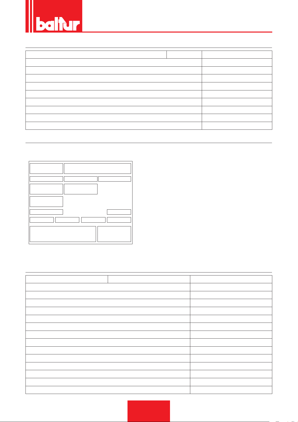
SUPPLIED MATERIAL
Targa_descr_bru
MODEL TBML 50MC
BURNER CONNECTION FLANGE 1
INSULATING SEAL 1
STUD BOLTS No. 4 - M12
HEXAGONAL NUTS No. 4 - M12
FLAT WASHERS No. 4 - Ø12
INSULATING ROPE 1
HOSES No. 2 - 1/2"x1/2"
FILTER 3/8"
NIPPLE(S) No. 2 - 1/2"x3/8"
BURNER IDENTIFICATION PLATE
1 Company logo
2 Company name
3 Product code
1 2
3 4 5
6 7
8
9
10 13
11
12
14
1615
4 Model
5 Serial number
6 Liquid fuel power
7 Gas fuel power
8 Gas fuel pressure
9 Liquid fuel viscosity
10 Fan motor power
11 Power supply voltage
12 Protection rating
13 Country of manufacture and homologation certicate numbers
14 Year of manufacture
15 -
16 Burner serial number bar code
ENGLISH
FIRST START UP RECORDING DATA
Model: Date: Now:
Type of gas
Lower Wobbe number
Lower caloric power
Gas ow
Min. gas ow rate
Max. gas ow rate
Min. gas power
Max. gas power
Network gas pressure
Gas pressure downstream of the stabiliser
CO
CO2
fume temperature
air temperature
7 / 44
0006160003_201510
Stm3/h
Stm³/h
Stm³/h
kW
kW
mbar
mbar
Page 54
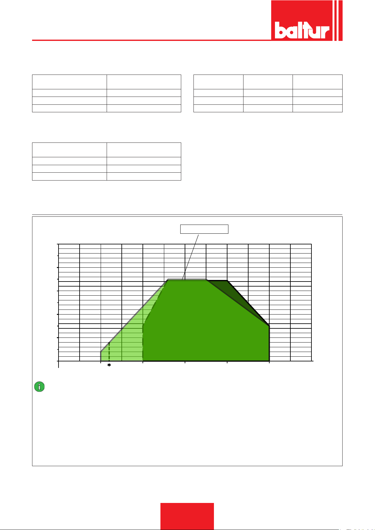
ENGLISH
¹) NATURAL GAS EMISSIONS
Classes dened according to Standard EN 676.
Class
1 ≤ 170
2 ≤ 120
3 ≤ 80
NOx emissions in mg/kWh -
natural gas
²) PROPANE EMISSIONS
CO emissions, natural gas/propane ≤ 100 mg/kWh
Class
1 ≤ 230
2 ≤ 180
3 ≤ 140
NOx emissions in mg/kWh -
propane gas
OPERATING RANGE
mbar
10
³) DIESEL EMISSIONS
Classes dened according to Standard EN 267.
Class
1 ≤ 250 ≤ 110
2 ≤ 185 ≤ 110
3 ≤ 120 ≤ 60
NOx emissions in mg/
kWh - diesel fuel
TBML 50 ME / MC
CO emissions in mg/
kWh - diesel fuel
8
6
4
2
0
100 200 300 400
IMPORTANT
The working elds are obtained from test boilers corresponding to the
standard EN267 for liquid fuels and EN676 for gas fuels and are indicative for the combination burner-boiler. For correct working of the
burner, the size of the combustion chamber must correspond to current
regulations; if not the manufacturers must be consulted.
The burner should not work outside the indicated work range.
500
Min thermal power TBML 50 LPG = 120kW
600
0002922890
kW
8 / 44
0006160003_201510
Page 55
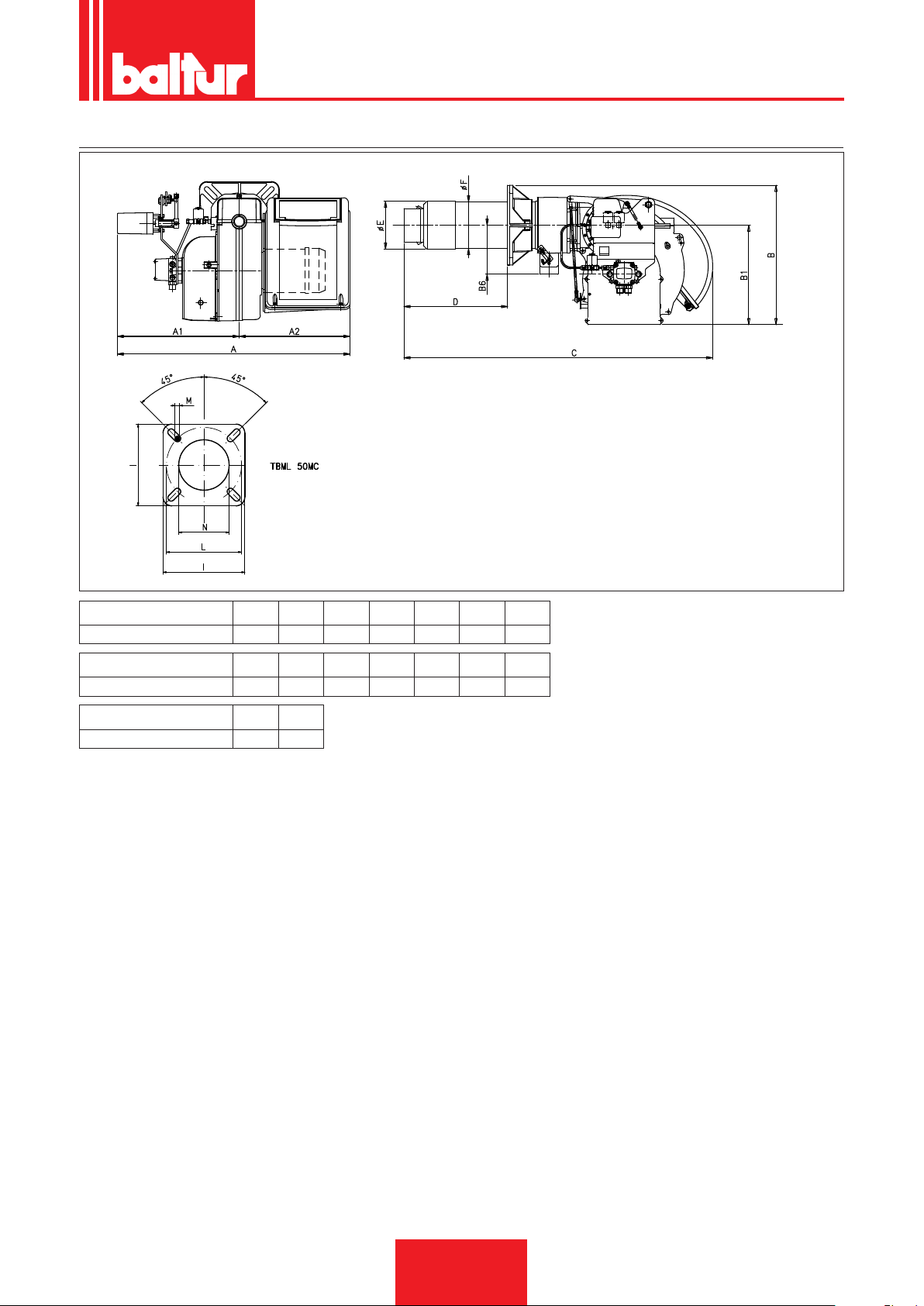
OVERALL DIMENSIONS
ENGLISH
0002471370N2
Model A A1 A2 B B1 B6 C
TBML 50MC 770 400 370 455 325 160 1020
Model D min D max E Ø F Ø I L min L max
TBML 50MC 170 340 156 152 260 225 300
Model M N Ø
TBML 50MC M12 160
9 / 44
0006160003_201510
Page 56
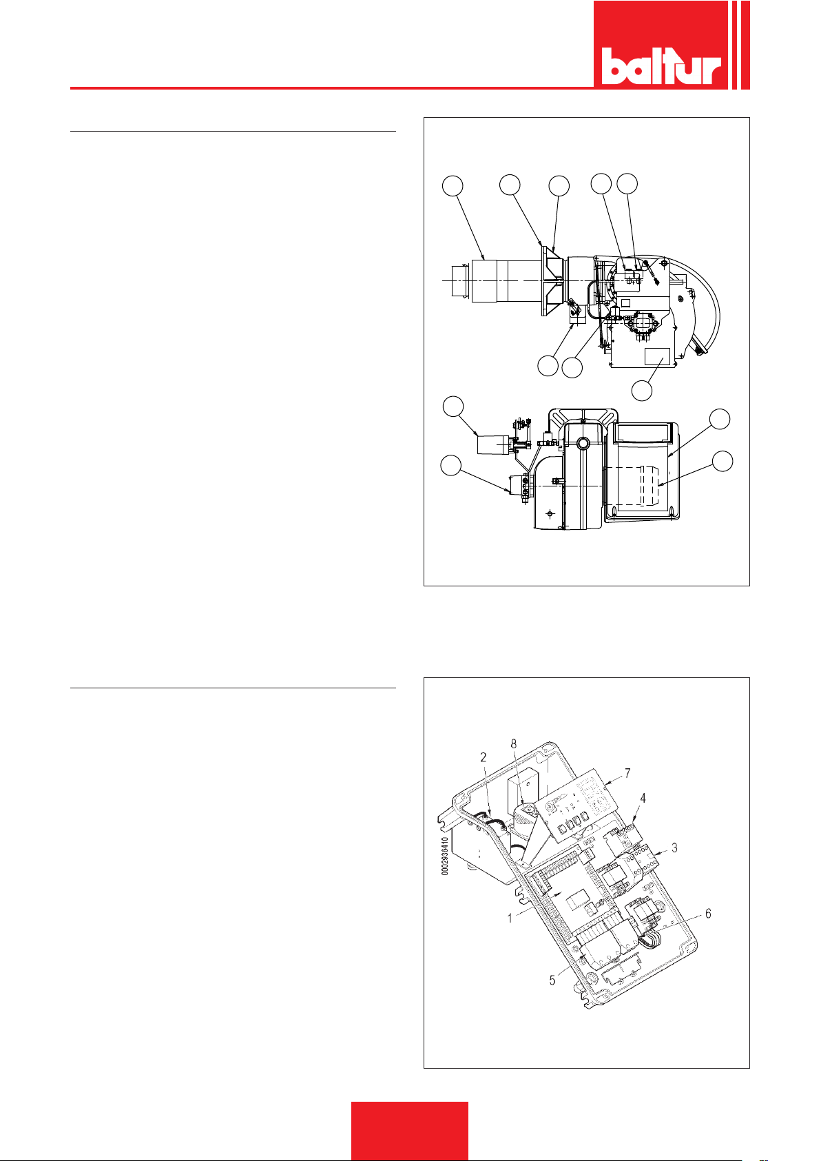
ENGLISH
COMPONENT DESCRIPTION
1 Combustion head
2 Seal
3 Burner connection ange
4 Gas train connector ange
5 1st Stage solenoid valve
6 Safety solenoid valve
7 2nd Stage solenoid valve
8 Air / gas regulation servomotor
9 Burner pump
10 Electrical panel
11 Motor
12 Burner identication plate
10
1
2
3
4
8 6
0002471370N1
7
14
12
ELECTRICAL PANEL
1 Control box
2 Ignition transformer
3 Motor contactor
4 Thermal Relay
5 7-pole connector
6 4-pole connector
7 Synoptic panel
8 Air pressure switch
11
13
10 / 44
0006160003_201510
Page 57
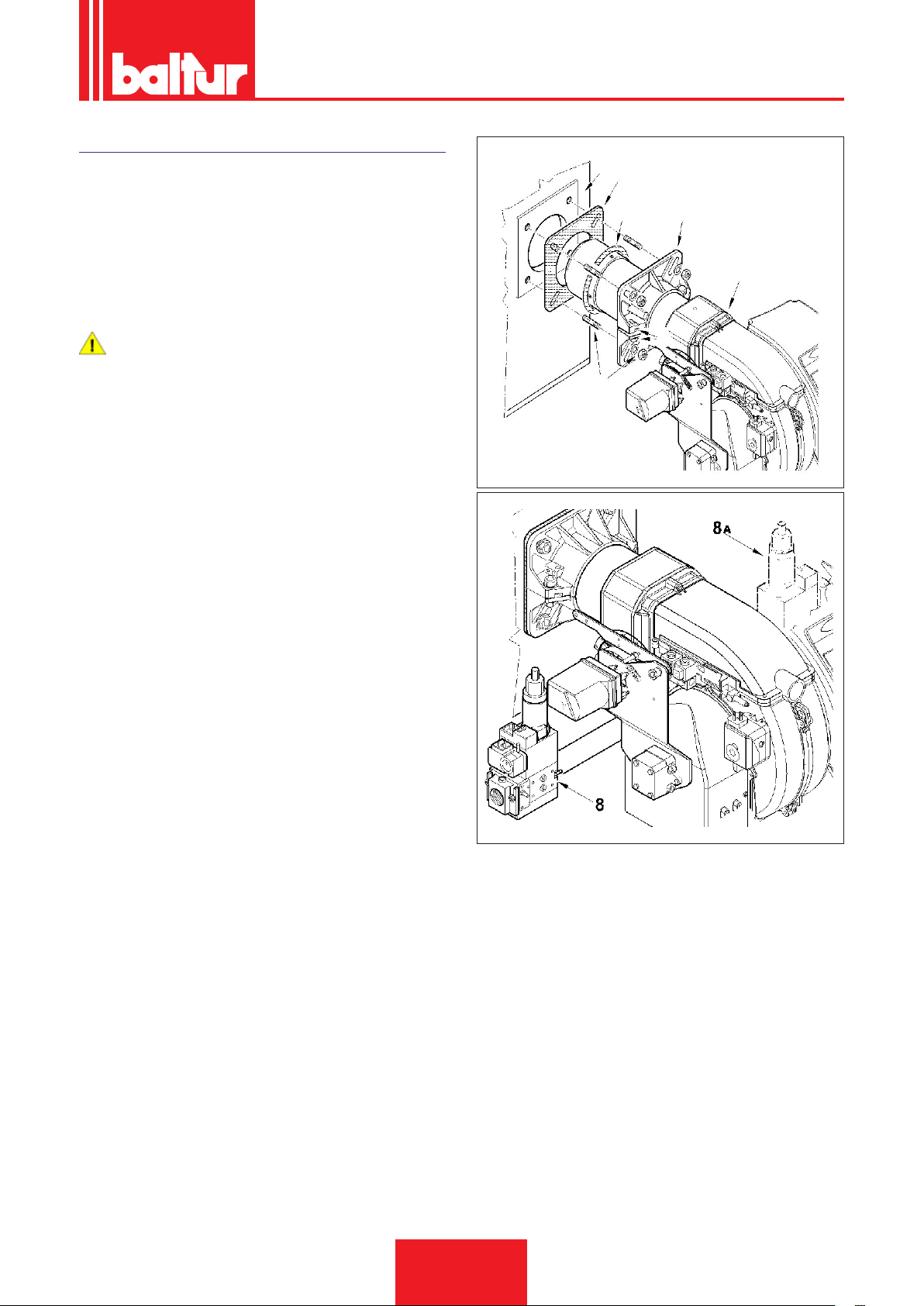
BURNER CONNECTION TO THE BOILER
0002937450
ASSEMBLING THE HEAD UNIT
• Position insulating seal -13 on the sleeve, placing rope -2
between the ange and the seal.
• Adjust the connection ange -19 position loosening the screws
-6. The burner head must penetrate to the extent requested by
the generator manufacturer.
• Fasten the burner -18 to the boiler -1 with the stud bolts, washers and nuts provided -7.
DANGER / CAUTION
Completely seal the gap between the burner sleeve and
the hole in the refractory material inside the boiler door with
suitable material.
ASSEMBLING THE GAS TRAIN
The EN 676 approved gas train is sold separately from the burner.
The gas train can be assembled in different ways: -8 and (8a).
ENGLISH
1
13
2
25
18
6
7
11 / 44
0006160003_201510
Page 58
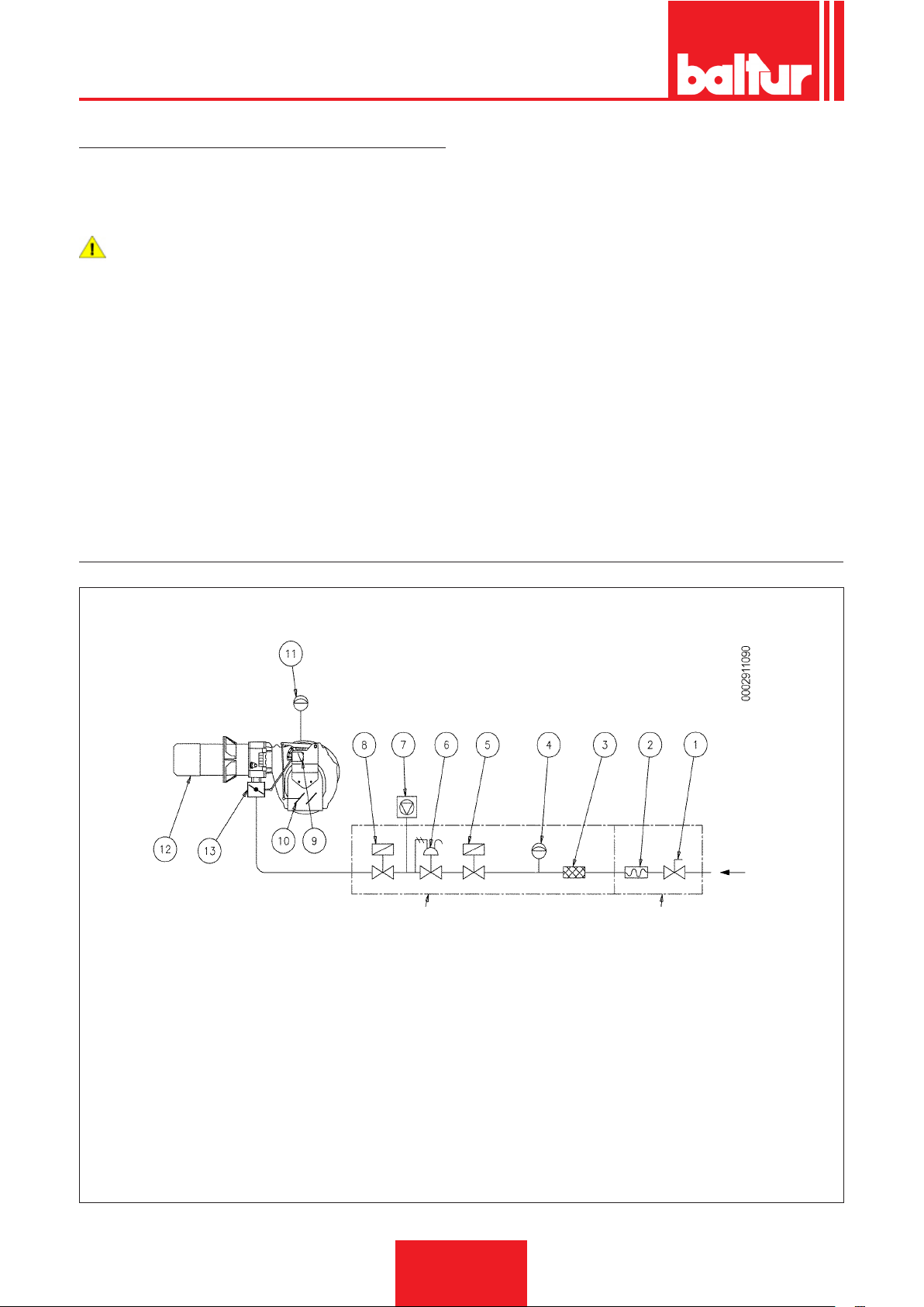
ENGLISH
GAS SUPPLY LINE
The basic diagram of the gas supply line is shown in the gure
below.
The gas train is certied in accordance with Standard EN 676 and
is supplied separately from the burner.
DANGER / CAUTION
Install a manual on/off valve upstream of the gas valve according to the layout shown in the diagram illustrating the
gas train principle.
GAS BURNER SCHEMATIC DIAGRAM
GAS TRAIN SUPPLIED BY THE MANUFACTURER RESPONSIBILITY OF THE INSTALLER
1 Manual shut-off valve
2 Vibration-proof joint
3 Gas lter
4 Minimum gas pressure switch
5 Safety valve
6 Pressure regulator.
7 Valve seal control device (mandatory for burners with maximum
rated heating capacity higher than 1200kW)
8 Slow opening operating valve
9 Air / gas regulation servomotor
10 Air regulation shutter
11 Air pressure switch
12 Combustion head
13 Gas regulation throttle valve
12 / 44
0006160003_201510
Page 59
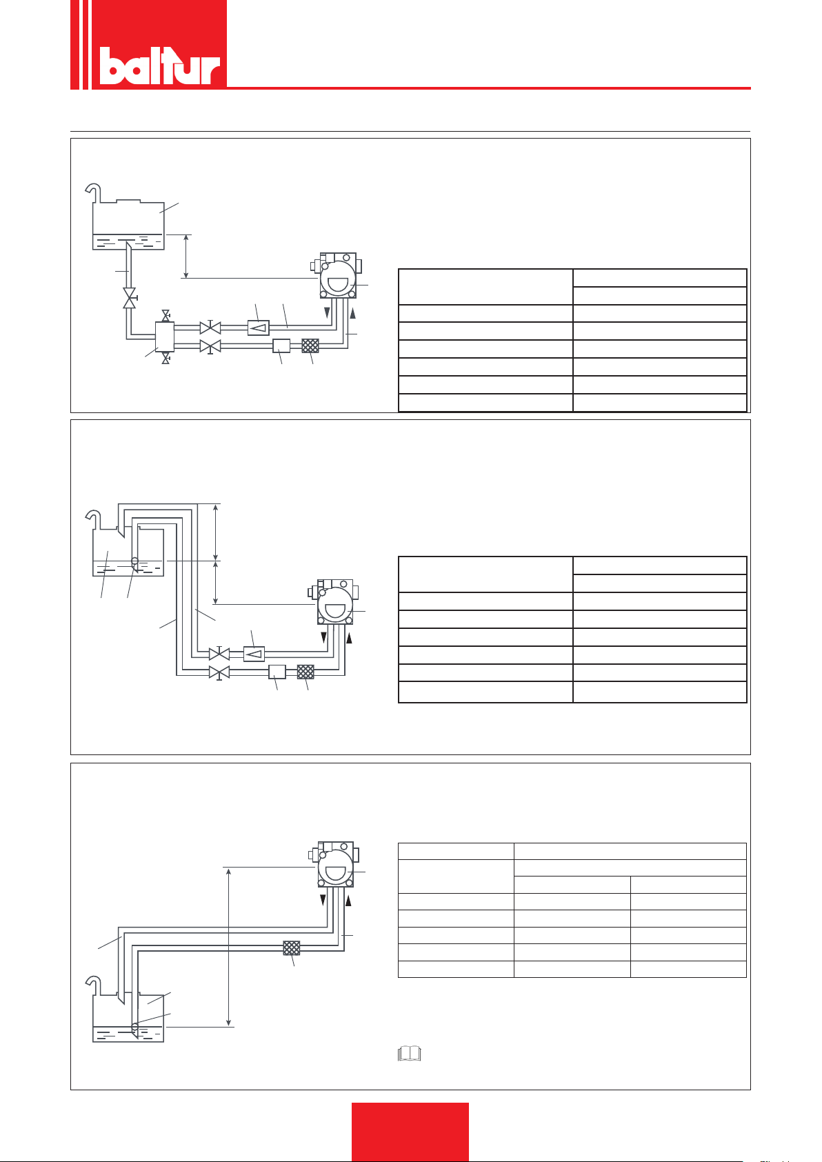
PIPELINE DIMENSION DIAGRAMS
0002900740N1
8
3
0002900740N2
ENGLISH
GRAVITY SUPPLY SYSTEM
1
H
2
4
9
7
6
5
8 3
SIPHON FEED SYSTEM WITH FEED FROM THE TOP OF
THE TANK
1 Tank
2 Feeding pipe
3 Mesh lter
4 Pump
5 Degasier
H Total L.
Meters Øi 14 mm
1 30
1,5 35
2 35
2,5 40
3 40
1 Tank
3 Mesh lter
4 Pump
6 Suction pipe
6 Suction pipe
7 Burner return pipe
8 Automatic shut-off device
9 Unidirectional valve
Meters
7 Return pipe
8 Automatic shut-off device
9 Unidirectional valve
10 Foot valve
with burner off
with burner off
10
1
6
INTAKE SUPPLY SYSTEM
7
1
10
H Total L.
H P
Meters Øi 14 mm
4
7
9
6
H
3
1 30
1,5 35
2 35
2,5 40
3 40
Value P = 3.5 m (Max)
1 Tank
3 Mesh lter
4 Pump
H Total L.
4
H - Height difference between minimum tank level and pump axis.
L - Total length of pipeline, including vertical length. Deduct 0.25 for each elbow or gate.
Meters
0,5 26 45
1 22 38
1,5 19 31
2 14 25
2,5 11 19
Meters
6 Suction pipe
7 Return pipe
10 Foot valve
Meters
Øi 14 mm Øi 16 mm
0002900740N3
0006160003_201510
CAUTION / WARNING
For any components missing in the pipes, comply with current regulations.
13 / 44
Page 60
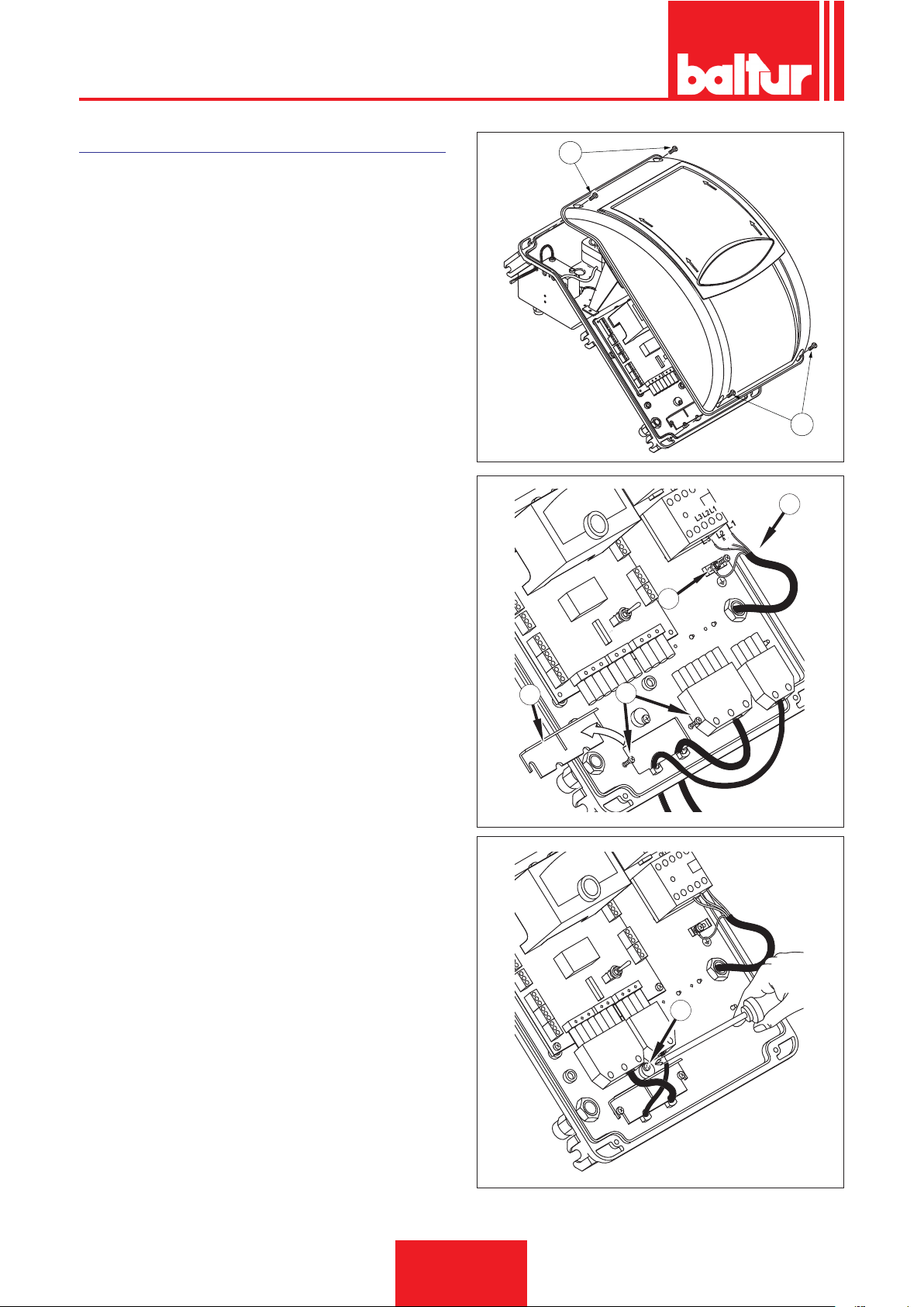
ENGLISH
ELECTRICAL CONNECTIONS
• Electrical lines must be kept away from hot parts.
• The burner installation is allowed only in environments with
pollution degree 2 as indicated in annex M of the EN 603351:2008-07 regulation.
• Make sure that the electric line to which the unit will be connected has frequency and voltage ratings suitable for the burner.
• The three-phase or single-phase power supply line must have
a switch with fuses. The standards also require a switch on the
burner's power line located outside the boiler room where it can
be accessed easily.
• The main line, the relevant switch with fuses and the possible
limiter must be suitable to support the maximum current absorbed by the burner.
• The mains supply connection requires an omnipolar switch with
a contact opening gap equal to or greater than 3 mm in accordance with current safety regulations.
• Refer to the wiring diagram for electrical connections (line and
thermostats).
• Unsheathe the external insulating cover of the power cable to
the necessary extent for the connection, thus avoiding the wire
from coming into contact with metal parts.
To carry out the connection of the burner to the power supply line
proceed as follows:
• Remove the cover by unscrewing the screws (1), without removing the transparent door. In this way the burner’s electrical
panel can be accessed.
• Loosen the screws (2) and after removing the cable clamp plate
(3), make the 7 pole plug, the 4 pole plug and the modulation
control cable come through the hole. Connect the power supply
cables (4) to the contactor, connect the cable to ground (5) and
close the cable holder.
• Reposition the cable clamp plate. Turn the cam (6) so that the
plate exerts sufcient pressure on the cables, then tighten the
screws that fasten the plate. Finally, connect the related plugs
and modulation command cable, if installed.
1
0002934780a
1
4
5
3
2
0002934780b
14 / 44
0006160003_201510
0002934780c
6
Page 61
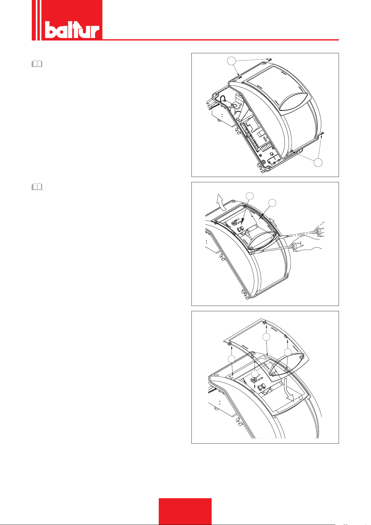
CAUTION / WARNING
1
The housings for the cables for the plugs are provided respectively for cable Ø 9.5÷10 mm and Ø 8.5÷9 mm, this ensures the protection rating is IP 54 (Standard IEC EN60529)
for the electrical panel.
• To reclose the electrical panel lid, x the screws (1) with a torque of about 5 Nm to ensure the correct seal.
To gain access to the control panel (8), slide the transparent door
(7) for a short distance following the direction on the arrow in-
dicated in the gure exerting slight pressure with a tool (e.g. a
screwdriver) following the arrows' direction and slide it for a short
distance to separate it from the cover.
• To secure the transparent door on the panel properly, position
the hooks at their hooking points (9), slide the door in the direction indicated by the arrow until you hear a click that ensures
its seal.
CAUTION / WARNING
Only professionally qualied personnel is allowed to open
the burner electrical panel.
ENGLISH
0002934780a
1
8
7
0002934780d1
9
9
9
9
0002934780e
15 / 44
0006160003_201510
Page 62

ENGLISH
DIESEL SUPPLY LINE
The following description covers the basic requirements to ensure
efcient operation.
The unit is equipped with a self-priming pump capable of sucking
oil directly from the tank also for the rst ll-up.This statement is
valid only if the necessary conditions exist, see the pipe dimensioning diagrams.
To ensure an efcient operation, it is better to make suction and
return pipes with welded ttings and to avoid the use of threaded
connections which often cause air inltration’s interfering with the
pump operation and consequently with the burner.
Where a removable tting is required, use the welded ange
method with a fuel resistant gasket inserted to ensure a perfect
sealing.For systems requiring pipes with a relatively small diameter, we recommend using copper pipes.
For unavoidable connections we recommend using "biconic" ttings.
These are the diagrams of the different types of systems depending on the position of the tank with respect to the burner.The
suction pipe should run up-slope towards the burner to avoid possible formation of gas bubbles.Where more than one burner is
installed in one boiler room, it is essential that each burner has its
own intake pipe.
Only return pipes can lead to a single manifold pipe with an adequate cross section leading to the tank. Never connect the return
pipe directly to the intake pipe.
It is advisable to properly insulate the intake and return pipes to
prevent cooling which would affect the unit’s efciency.Pipe diameters (to be strictly complied with are listed in the following table.
The maximum amount of vacuum that the pump can withstand
noiselessly under normal operating conditions is 0.47 bar; if these
limit is exceeded normal pump operation will no longer be guaranteed.
Maximum pressure at intake and return = 1 bar.
AUXILIARY PUMP
In some cases (excessive distance or differences in level) the system must be implemented with a "loop" supply circuit with an
auxiliary pump, avoiding to connect the burner pump directly to
the tank.
In this case, the auxiliary pump can be started when the burner
starts and stopped when it stops.
The electric connection of the auxiliary pump is made by connecting the coil (230V) that controls the pump's remote control
switch to terminals 2 (N) and 17 on the printed circuit.
It is important to comply strictly with the previsions set forth here
below:
• The auxiliary pump must be installed as close as possible to the
liquid to be sucked.
• The head must be suitable for the relative plant.
• We recommend a ow rate that is at least equal to the ow rate
of the burner pump.
• Connection pipes should be sized to cope with the delivery rate
of the auxiliary pump.
• Absolutely avoid electrically connecting the auxiliary pump di-
rectly to the contactor of the burner.
• Set the pressure to about 0.5 bar ÷ 1 bar if the circuit is tted
with pressure regulator.
16 / 44
0006160003_201510
Page 63
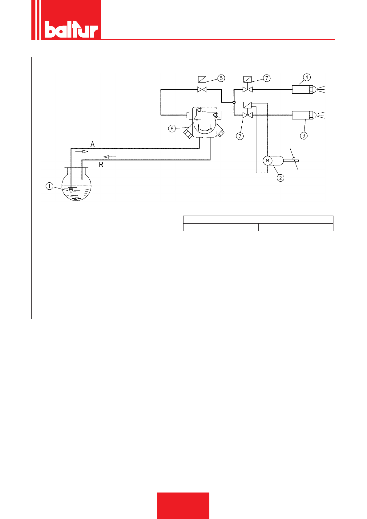
GENERAL OUTLINE DIAGRAM OF HYDRAULIC CIRCUIT
ENGLISH
1 Foot valve
2 Air regulation servomotor
3 2nd stage nozzle
4 1st stage nozzle
5 Safety valve normally closed
6 Pump 12 bar
7 Valve normally closed
A Intake
R Return
Hydraulic circuit loss of head
TBML 50MC 1 bar
17 / 44
0006160003_201510
Page 64

ENGLISH
DESCRIPTION OF OPERATION WITH
LIQUID FUEL
FURTHER INSTRUCTIONS TO START A MIXED BURNER
It is advisable to perform the rst ignition with liquid fuel (switch
2 in ON position, Oil led comes on) because in this case delivery is conditioned by the available nozzle, whereas the delivery
of methane can be varied as you like by adjusting its ow-rate
regulator.
It is not advisable to have too large a burner for the boiler for
heating and for hot water as the burner may work for long periods
with a single ame, making the boiler work at lower than required
output; as a result of this the combustion products (fumes) emerge
at too low a temperature (at about 180°C in the case of heavy
oil and 130°C with diesel fuel), causing soot to build up at the
chimney outlet.
In addition, when the boiler is working at lower output than that
indicated by the technicians, it is likely that acidic condensate and
soot will form in the boiler with the result that it will quickly corrode
and get clogged up.
When the two-ame burner is installed on a water boiler for heating use, it must be connected so that it works normally with both
ames, completely stopping without passing to the rst ame
when the preset temperature is reached.
To obtain this operating condition, do not install the second ame
thermostat and make a direct connection (bridge) between the respective four pole plug terminals.
In this way only the burner’s capacity to switch on at low rate is
used for a gentle ignition, which is essential for boilers with a pressurised combustion chamber and also very useful for normal boilers with depression combustion chamber. The burner (start/stop)
command is subject to the usual operating or safety thermostats.
Closing the switch (1), if the thermostats are closed, the voltage
reaches the command and control equipment (LED 2 start-up)
which starts the operation cycle. The fan motor (LED 3) and the
ignition transformer (LED 5) are then switched on.
The motor turns the fan that carries out an air wash of the combustion chamber and, at the same time, the fuel pump that causes
circulation in the ducts, expelling any gas bubbles through the
return valve. This pre-wash stage ends with the opening of the
safety and rst stage solenoid valves (LED 6), which allows the
fuel at a pressure of 12 bar to get to the rst stage nozzle and from
this to enter the combustion chamber nely atomised.
As soon as the atomized fuel exits the nozzle, it is set on re by
the spark present between the electrodes since the start of the
motor.
During rst stage ignition, the air gate is held in the adjusted position on the special air/gas adjustment servomotor cam.
If the ame appears regularly, after the safety time foreseen by
the device, it starts the air/gas regulation servomotor that moves
to the second stage position. During the transition from the rst
to the second stage, the servomotor activates the solenoid valve
(normally closed) of the second stage (LED 4).
The opening of the second ame valve allows the diesel oil, at a
pressure of 12 bar, to reach the second nozzle and the burner to
operate at full capacity.
Once the ame appears in the combustion chamber, the burner
is controlled and commanded by the ame control equipment and
by the thermostats.
The control equipment follows the program and switches the ignition transformer off. When the temperature or the pressure in the
boiler reaches that set by the thermostat or pressure switch, the
latter stops the burner.
Subsequently, if the temperature of pressure decreases below the
lower thermostat or pressure switch threshold value, the burner
will switch on again.
If, for any reason, the ame fails during operation, after just one
second the ame control device cuts off the power supply to the
relay, causing the deactivation of the solenoid valves which inter-
cept the fuel ow to the nozzles.
The switch on stage is thus repeated and, if the ame ignites
again normally, the burner starts working again normally, if not
(if the ame is irregular or fails to light completely) the equipment
goes automatically into lock-out (LED 5 comes on).
18 / 44
0006160003_201510
Page 65
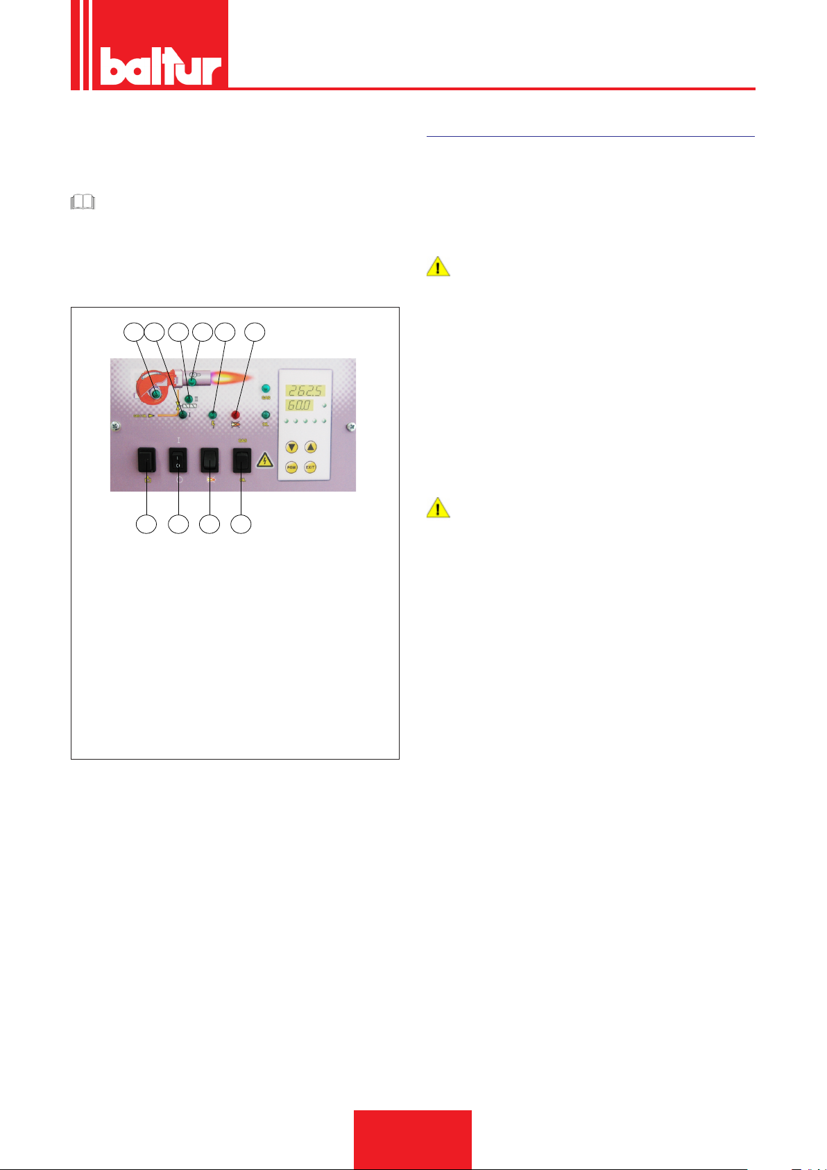
ENGLISH
Display_TBML_80pn
If the program is interrupted (power failure, manual intervention,
thermostat intervention, etc...) during the prewashing phase the
programmer will return to its initial position and will automatically
repeat the entire burner ignition phase.
CAUTION / WARNING
The selection of the nozzles in relation to the desired total
ow rate (2 nozzles in operation) must be made taking into
consideration the ow rate values that correspond to the
diesel operating pressure of 12 bar. Replacing the nozzles it
is possible to vary greatly the relationship between the rst
and the second stage.
3 6 4 5 2 7
9 1 8 10
1 ON / OFF main switch.
2 Fuel switch.
3 Liquid fuel operation warning light.
5 Gaseous fuel operation
warning light.
4 Equipment shut-down
6 1st stage operation indicator light
7 Control box lock-out indicator light
8 Control box reset button
9 Fuel ll button
10 Fuel selector switch
warning light.
FIRST PIPELINE FILLING UP
After checking that the protective plastic caps on the pump ttings
have been removed, proceed as follows:
• Turn the switch on the burner to the “O” position to avoid the
burner automatic activation.
• Make sure the line voltage is the same as indicated in the iden-
tication plate of the burner.
DANGER / CAUTION
To positively determine the direction of rotation, wait until
the fan turns very slowly because it is quite easy to misinterpret the direction of rotation.
• Detach, if already attached, the exible hoses from the intake
and return pipes.
• Dip the end of the suction hose into a vessel containing either
lubrication oil or diesel (do not use low viscosity products such
as petrol, kerosene, etc.).
• Now press key (9) on the control panel to start the motor and
the pump. Wait until the pump has sucked an amount of lubricant equal to 1 or 2 glasses, then stop. This operation will prevent the pump from operating dry and will increase the suction
power.
DANGER / CAUTION
Pump operating at 2800 r.p.m. must not work dry otherwise
they will jam (seizure) within a very short time.
• Attach the exible hose to the intake pipe and open any gate
valves tted on this pipe and any other shut-off element on the
fuel pipes.
• Press button (9) again to start up the pump that extracts the fuel
from the tank.
• When you see the fuel coming out of the return line (not yet
connected), stop.
19 / 44
0006160003_201510
Page 66

ENGLISH
DANGER / CAUTION
If the pipe is long, it may be necessary to bleed the air out
through the cap; if the pump is not tted with a cap, remove
the pressure gauge connector cap.
• Connect the return exible hose to the return pipe and open the
gates tted on this pipe. Now the burner is ready for lighting up.
IGNITION AND ADJUSTMENT WITH LIQUID FUEL
Before starting up, make sure that:
• The correct type of fuel has been selected.
• Connections to the supply line, to thermostats or pressure swi-
tches, have been made according to the electrical diagram of
the equipment.
• Check if there is fuel in the tank and water in the boiler.
• All the gate valves tted on the fuel oil intake and return pipes
are open, as well as any other shut-off element on the fuel pipes.
• Make sure that discharge of combustion products takes place
freely (boiler and ue shutter open).
• Check that combustion head penetrates the combustion cham-
ber by the measure requested by the manufacturer of the boiler.
Check that the air closure device on the combustion head is
in the right position to guarantee a correct combustion, the air
passage between disk and head must be slightly reduced if a
relatively small amount of fuel is supplied. When the fuel supply
is abundant the air passage must be increased, see chapter
"COMBUSTION HEAD ADJUSTMENT”.
• The nozzles tted on the burner should match the boiler capacity but, if necessary, replace them with others. In no case should
the quantity of fuel delivered exceed the maximum amount required by the boiler and the maximum amount allowed for the
burner.
To start the burner proceed as follows:
DANGER / CAUTION
Prevent operation of the second ame avoiding to connect
the 4-pin connector (2nd stage).
• Adjust the quantity of air considered necessary for 1st stage
ignition through the relevant air/gas regulation servomotor cam.
• Turn on the main switch and the one on the control panel.
• The programmer is activated and it starts carrying out the pre-
dened program activating the burner devices.The equipment
will start operation as described in the Chapter “DESCRIPTION
OF OPERATION”.
20 / 44
0006160003_201510
Page 67
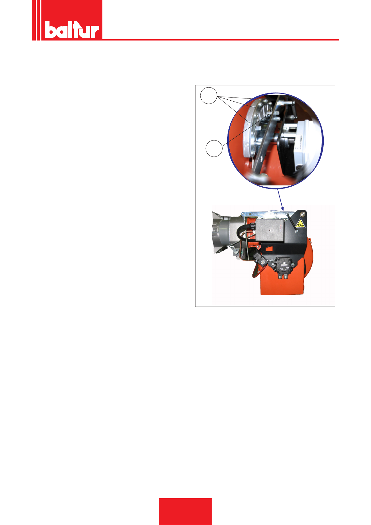
• When the burner is operating in the 1st stage, adjust the amount
img 010.jpg
of air necessary to ensure an efcient combustion, see “AIR
ADJUSTMENT ON THE BURNER HEAD” and 0002937920 for
the diesel 1st stage cam adjustment.
• After adjusting the 1st stage air the burner stops disconnecting
the current from the main switch, the electric circuit commanding the second stage activation closes connecting the 4-pole
connector according to the wiring diagram.
• Adjust the quantity of air necessary for the maximum ow rate
(2nd stage) through the screw/s at the bearing -12.
- clockwise rotation: the air ow increases
- in an anti-clockwise direction the air ow decreases
• Now the equipment is activated again and moves to the second
stage automatically, according to the program set by the programmer.
ENGLISH
12
acc_reg001.psd
13
21 / 44
0006160003_201510
Page 68
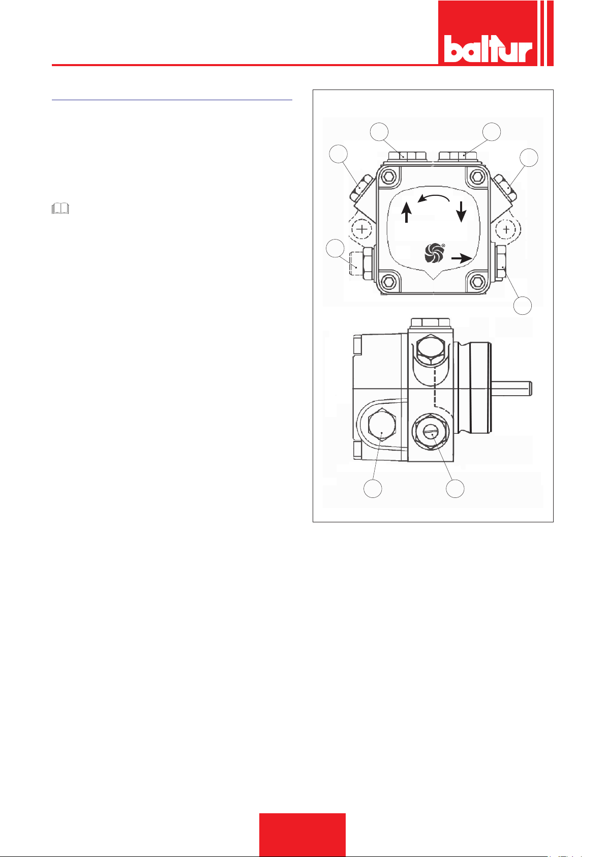
ENGLISH
AN 47 - 57 - 67 - 77 - 97
PUMP PARTS
2 Pressure gauge connector and air vent (1/8” G)
3 Pressure adjustment screw AN77... 10 - 20bars
4.1 Return with internal BY-PASS dowel
5 Suction
6 Delivery to nozzle
7 Vacuum gauge connector (1/8” G)
7.1 Vacuum gauge connector and internal BY-PASS dowel
CAUTION / WARNING
The pump is preset at a pressure of 12 bar
4.1 5
2
2
3
6
67
0002900331
22 / 44
0006160003_201510
Page 69
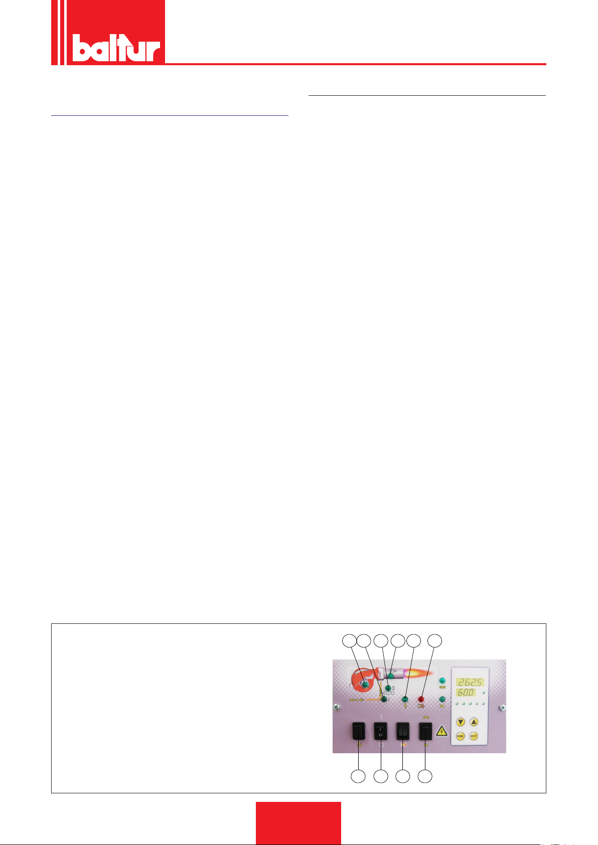
ENGLISH
Display_TBML_80pn
OPERATION DESCRIPTION WITH GASEOUS FUEL
Switching on the switch "1", if the thermostats are on, voltage reaches the control box (LED 2 switches on) which starts operating.
Then the fan motor is activated (LED 3) in order to carry out the
pre-ventilation of the combustion chamber, at the same time the
servomotor commanding the air damper is moved to the opening
position corresponding to the set maximum power.
At the end of the preventilation stage the air damper goes back to
the 1st ame position. If the air ventilation control pressure switch
has found that there is sufcient pressure, the ignition transformer
(LED 5) will come on, and two seconds later the safety and main
gas valves will open.
In particular:
• The main valve is a slow opening single-stage valve
• The safety valve is an ON/OFF valve
• The air damper is activated by a dedicated electric servomotor,
keep in mind that when the burner is locked out because the
thermostat is tripped, the servomotor returns the air damper to
the closed position.
The presence of the ame, detected by the control device, permits continuation and completion of ignition, turning off the ignition
transformer.
If there is no ame, the apparatus shut down in “safety lock-out”
mode (lock warning light 7) within three seconds of the opening
of the main valve. In safety lock-out mode the valves are closed
again immediately. To release the equipment from this safety position, press button "8" on the control panel.
MODULATION OPERATION DESCRIPTION
When the burner is on at minimum ow rate, if the modulation
probe allows it (set to a temperature or pressure value higher than
that in the boiler) the air/gas regulation servomotor starts turning;
• in a clockwise direction the air ow increases;
• anticlockwise rotation: the air ow decreases.
thus gradually increasing gas supply and combustion air until the
maximum supply level set for the burner is reached.
The burner remains in the maximum ow position until the temperature or pressure is high enough to trip the modulation probe,
which reverses the rotation of the air adjustment servomotor.
The inverse rotation and therefore the air and gas supply reduction
occurs shortly thereafter.
With this procedure, the modulation system attempts to balance the amount of heat supplied to the boiler with respect to the
amount the boiler releases for use.
The modulation probe installed on the boiler measures any variation requests and automatically adjusts fuel and combustion air
supply, by starting the air/gas regulation servomotor and increasing or reducing rotation as necessary.
If the limit value (temperature or pressure) at which the stop device is set (thermostat or pressure switch) is reached even with gas
supply at minimum level, the burner is shut down by the device.
When temperature or pressure returns below the shut-down device tripping value, the burner is activated once again according to
the program described in the previous section.
1 ON / OFF main switch.
2 Fuel switch.
3 Liquid fuel operation warning light.
5 Gaseous fuel operation warning light.
4 Equipment shut-down warning light.
6 1st stage operation indicator light
7 Control box lock-out indicator light
8 Control box reset button
9 Fuel ll button
10 Fuel selector switch
3 6 4 5 2 7
9 1 8 10
23 / 44
0006160003_201510
Page 70
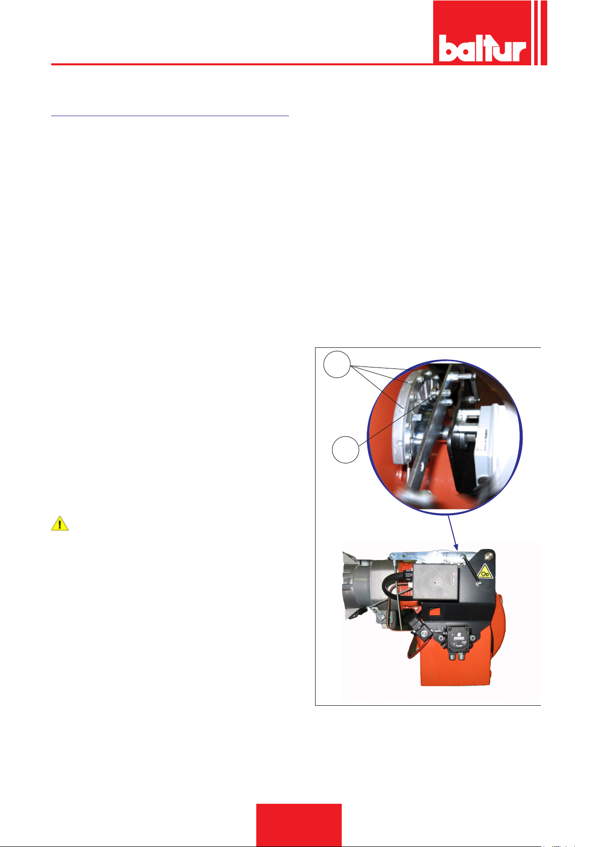
ENGLISH
img 010.jpg
NATURAL GAS IGNITION AND REGULATION
• Position the rst ame gas ow rate regulation cam on the
electric servomotor to an opening angle approximately between
15° and 20°.
• Now switch on the switch START/STOP switch of the burner
panel. The control equipment thus receives voltage and the
programmer causes the burner to switch on as described in the
chapter “operation description”. During pre-ventilation, make
sure that the air pressure control switch changes its status (from
the closed position without pressure measurement to the closed
position with pressure measurement). If the air pressure switch
does not detect sufcient pressure, the ignition transformer is
not switched on, nor are the gas valves, and so the equipment
is stopped in “lock-out” mode.
• On rst switching on repeated “lock outs” may occur due to the
following reasons:
• The gas piping is not being freed of air correctly and so there is
not enough gas to provide a stable ame.
• A “lock out” with ame presence could be caused by ame in-
stability due to an incorrect air/gas ratio. This can be solved by
changing the amount of air and/or gas supplied, so as to nd
the right ratio. The same problem may be caused by incorrect
air/gas distribution in the combustion head. This can be solved
through the combustion head regulation device, by closing or
opening further the air passage between combustion head and
gas diffuser.
• Correct the rst stage air supply ow rate through the screw/s
(12) at the bearing (13).
- In clockwise rotation the air ow increases
- In anticlockwise rotation the air ow decreases
• After adjusting the regulation for the rst ignition, turn off the
burner and close the electrical circuit commanding inclusion of
the second stage.
• Adjust the gas ow using the valve pressure regulator, until you
obtain optimal combustion values, without modifying the initial
air setting for diesel oil. Consult the instructions related to the
single stage gas valve model installed. Avoid keeping the burner running if the heating capacity is greater than the maximum
amount allowed for the boiler, to avoid damaging it.
• Check the combustion parameters with appropriate instruments
(CO2 MAX=10% O2 MIN= 3% CO MAX=0.1%)
At the end of burner adjustment in the second stage, open the
electric circuit controlling the 2nd stage activation without varying
the regulation of the gas valve already undertaken in the previous
point.
• Set the rst stage gas ow rate to the needed value through the
electric servomotor.
• If necessary, correct the combustion air supply adjusting the
screw/s (12) as described previously.
• Check the combustion parameters in the 1st stage with ap-
propriate instruments (CO2 MAX=10% O2 MIN= 3% CO
MAX=0.1%)
12
acc_reg001.psd
13
DANGER / CAUTION
Check that the electric servomotor second stage gas ow
rate regulation cam is positioned at 130°.
• Switch the burner on again activating the main switch -1 on the
synoptic panel. The burner will switch on automatically and activate the second stage. With the aid of appropriate instruments,
attend to the regulation of the air and gas ow according to the
procedures subsequently described:
0006160003_201510
24 / 44
Page 71

ENGLISH
• The air pressure switch prevents the opening of the gas valves
if the air pressure is not the foreseen one. The pressure switch must therefore be adjusted to intervene closing the contact
when the air pressure in the burner reaches a sufcient value.
If the air pressure switch does not detect pressure greater than
that calibrated, the equipment runs through its cycle but does
not switch on the ignition transformer and does not open the
gas valves and so the burner “locks-out”. To ensure correct working of the air pressure switch, you must, with burner on and
with rst ame only, increase the regulation until it is triggered
and immediately locks-out the burner. Release the burner by
pushing the appropriate button and readjust the pressure switch
to a sufcient value to detect the existing air pressure during the
operation phase of the 1st stage.
• The gas control pressure switch (minimum) prevents burner
operation when gas pressure is not the foreseen one. It is cle-
ar from the specic function of the pressure switches that the
control pressure switch for minimum pressure must make use
of the contact that is closed when the pressure switch detects
pressure greater than that for which it is regulated.
DANGER / CAUTION
Once the adjusting operations are completed, visually
check that the thin plate on which the bearing acts has a
progressive prole. Also check trough the dedicated tools
that during the passage between 1st and 2nd stage the
combustion parameters do not excessively vary from the
optimal values.
UV PHOTOCELL
Even the slightest greasiness will compromise the passage of the
ultraviolet rays through the UV photocell bulb, thus preventing the
sensitive internal element from receiving the quantity of radiation
necessary for it to work properly. If the bulb is fouled with diesel,
fuel oil, etc... it must be properly cleaned.
CAUTION / WARNING
Even by simply touching the bulb with ngers, it is possible
to leave a slight greasiness which could compromise UV
photocell operation.
The UV cell does not detect daylight or the light from a common
lamp. Sensitivity can be checked with a ame (cigarette lighter,
candle) or with the electric discharge between the electrodes of
a common ignition transformer. To ensure proper operation, the
UV cell current value should be sufciently stable and should not
drop below the minimum value required by the specic equipment;
this value is indicated in the wiring diagram. It may be necessary
to search for the best position by sliding (axial or rotational movement) the casing that contains the photocell with respect to
the fastening clamp. This can be checked by connecting a micro-ammeter, with a suitable scale, in series to one of the two UV
photocell connection cables. Obviously the + and - polarity must
be respected. The ...equipment needs a cell current between 200
and 500 microA.
25 / 44
0006160003_201510
Page 72
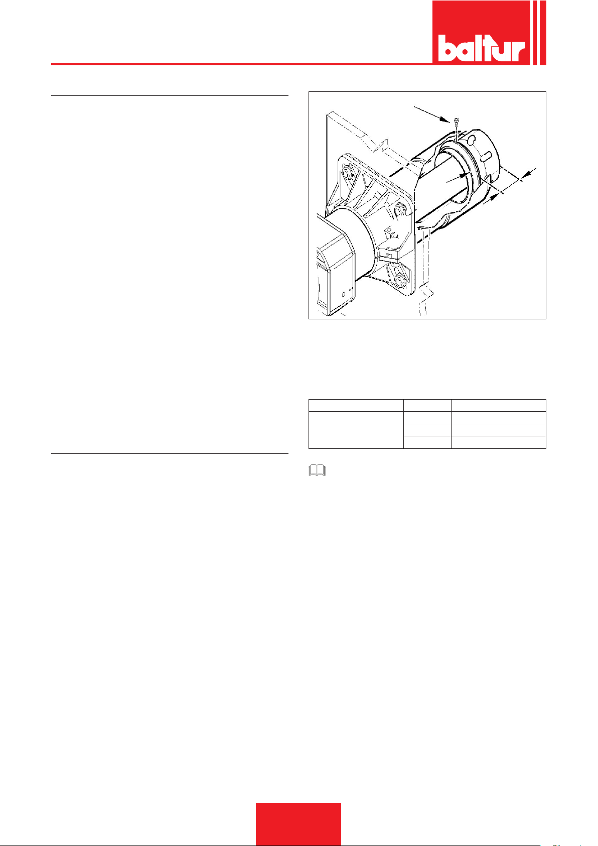
ENGLISH
0002937500
CONTROLS
• After starting up the burner, check the safety devices (ame
detector, lock-out system, thermostats)
• The ame control device should trip if the ame extinguishes
during operation (this check should be made after at least 1
minute after ignition)
• The burner should be able to lock out and remain locked when,
during the ignition sequence in the time pre-set by the control
box, the ame does not regularly appear. The lock-out causes
the immediate stop of the motor and burner and the switching
on of the corresponding lock-out light indication. To check the
efciency of the ame detector and lock-out system, proceed
as follows:
- Start the burner.
- After at least one minute from ignition, remove the ame
detector by sliding it out of its housing, cover it to simulate
ame failure (use a rag to cover the opening on the ame
detector). The burner ame must go out. The control box
locks out within the time set by the program. Reset the control box only by manually pressing the appropriate button.
- To check for the thermostats' efciency, make the burner
work until the water inside the boiler reaches a temperature
of at least 50°C. Then, use the thermostat control knob to
reduce the temperature until you perceive an opening click
and the burner stopping at the same time. The thermostat
should trip within a maximum tolerance of 5 to 10 °C in
respect to the control thermometer (boiler thermometer); if
not, change the setting on the thermostat scale to match
that of the thermometer.
AIR REGULATION ON THE COMBUSTION HEAD
The combustion head has a regulation device that allows the air
passage between the disc and the combustion head to be opened
or closed.
You are thus able to obtain, closing the passage, high pressure
upstream of the disk even at low ow rates.
The high speed and turbulence of the air provides for its greater
penetration into the fuel and therefore an excellent mixture and
ame stability.High air pressure upstream of the disk may be necessary to prevent ame uctuations, this is particularly essential
when the burner works on the furnace that is pressurised and/or
at a high thermal load.
Therefore, the air regulation device on the combustion head
should be put in such a position as to always obtain a decidedly
high air pressure value behind the disk.
Correct the position of the device that closes the air of the combustion head, moving it forward or backward, in order to obtain an air
ow suitable for the supply with the air damper considerably open.
In order to achieve this, you need to secure the device in an intermediate position on the head air closure and use the air damper
device to increase the ow to the fan intake. Obviously, this condition must occur when the burner is working at the maximum power
required by the system.
1
2
X
X= Combustion head-disk distance; adjust the distance X following the indications below:
• Adjust distance X of the air regulation ring (2) according to the
indications in the table.
• Tighten screw (1).
BURNER X POWER kW
65 ÷ 66 260 ÷ 350
TBML 50 MC / ME
CAUTION / WARNING
The above adjustments are indicative only; position the
combustion head according to the characteristics of the
combustion chamber.
70 ÷ 71 350 ÷ 430
78 ÷ 79 430 ÷ 500
26 / 44
0006160003_201510
Page 73
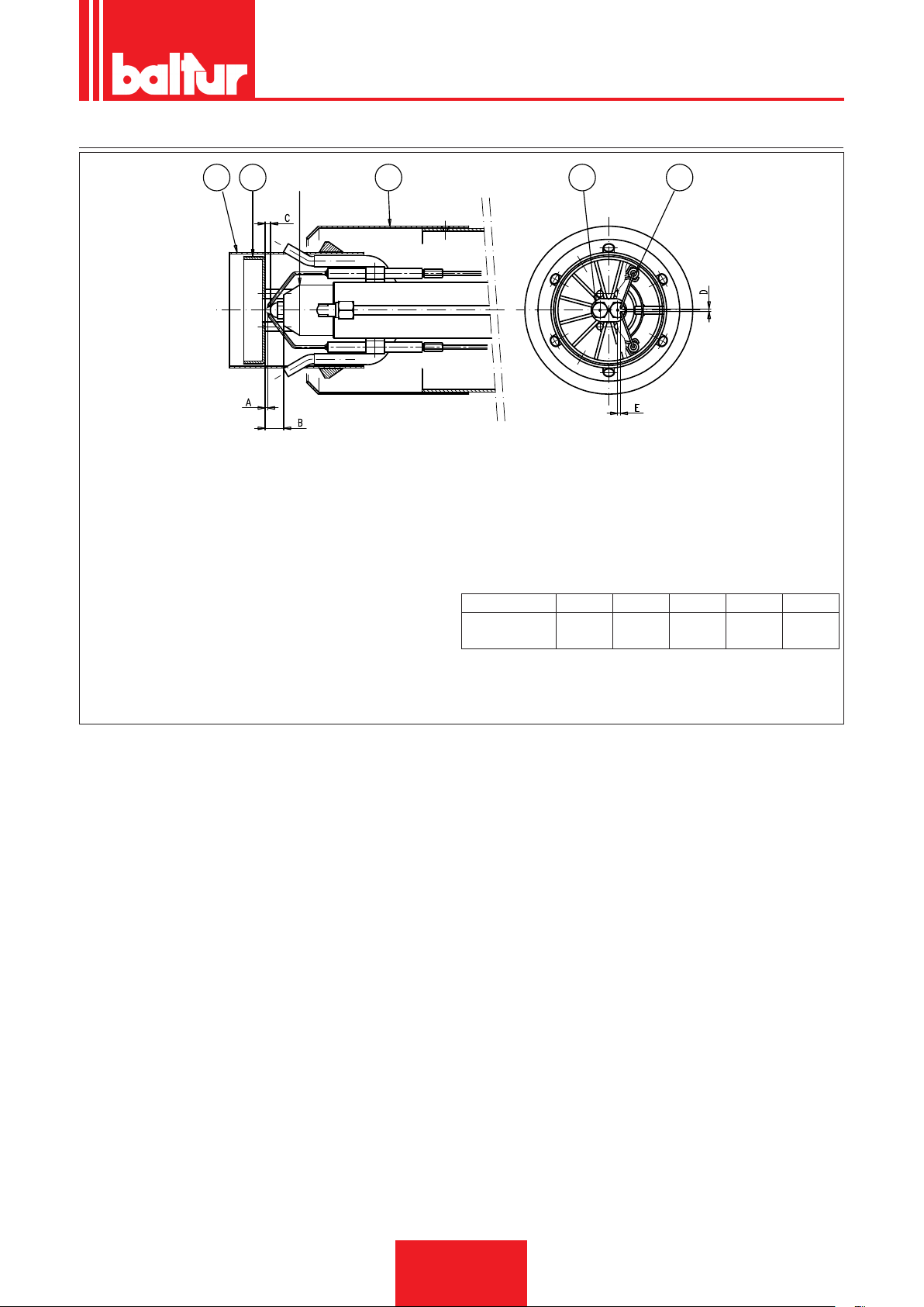
DIAGRAM FOR THE REGULATION OF THE ELECTRODE DISK DISTANCE
12 3 5 4
ENGLISH
0002937420
1 - Diffuser
2 - Internal diffuser
3 - Flame disk
4 - Ignition electrode
5 - Nozzles
6 - Nozzle holder
RECOMMENDED NOZZLES = MONARCH 30° HV° type
After installing the nozzles, make sure that the electrodes and disk
are correctly positioned according to the values indicated in mm.
It’s advisable to check values after every intervention on head.
A B C D E
TBML 50 MC
/ ME
1 ÷ 2 17 3 ÷ 4 3 ÷ 4 4 ÷ 5
27 / 44
0006160003_201510
Page 74
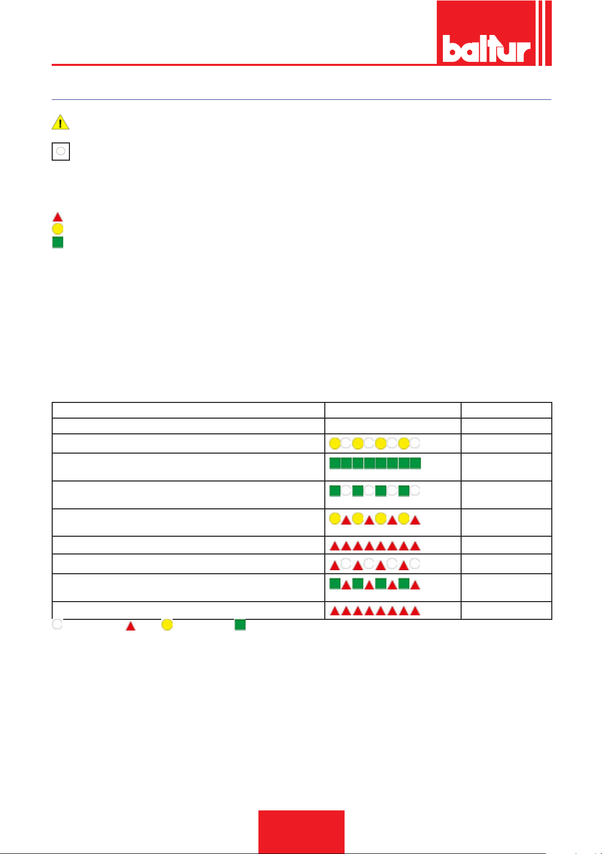
ENGLISH
↵
Info
LME 73...CONTROL BOX
for further information please refer to the Equipment Quick Guide supplied with the manual.
The lock-out reset button ') (info button) (EK) is the key element to reset the burner control and activate/deactivate diagnostics functions.
The indicator light (LED) is the indicative key element for visual diagnostics.
RED
YELLOW
GREEN
The lock-out reset button (EK) and the multicolour indicator light (LED) are both located on the control panel
Possibility of two diagnostic functions:
1. Visual diagnostics: indication of the operating status or diagnostics of the lock-out cause.
2. Diagnostics: display and operating unit through BCI up to AZL2 ...
visual diagnostics: during normal operation, the various operating statuses are indicated by colour codes according to the colour table
below.
OPERATING STATUS INDICATIONS
During ignition, there are the following status indications as per the table below:
Colour code table for the indicator light (LED).
Condition Colour sequence Colours
Waiting conditions TW, other intermediate statuses . . . . . . . . No light
Ignition phase
Correct operation, current strength of ame detector above the mini-
Intermittent yellow
Green
mum allowed
Incorrect operation, current strength of ame detector below the mini-
Intermittent green
mum allowed
Decrease in power supply voltage
Alternating Yellow
and Red
Burner in lock condition
Fault indication (see colour legend)
Extraneous light upon burner start-up
Red
Intermittent red
Alternating Green
and Red
Quick ashing for diagnostics
Quick ashing red
NO LIGHT. RED. YELLOW. GREEN.
28 / 44
0006160003_201510
Page 75
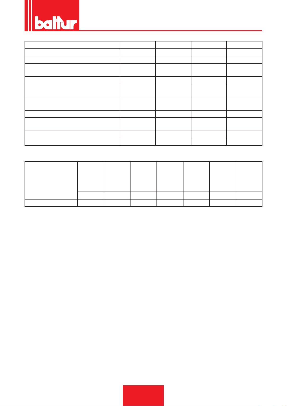
Type reference PME73.810A2 PME73.820A2 PME73.830A2 PME73.840A2
To be used with LME73.000A • • • •
Gas program for burner with fan • • • •
Single-stage / two-stage or modulating sin-
• • • •
gle-stage
Simultaneous/alternating pilot burner - - • •
Modulation by means of actuator (pneumatic or
• • • •
mechanical control of the gas/air ratio)
Actuator control with analogue signal/3-point
• - • -
signal for actuators with potentiometer
3-point signal for actuators with potentiometer - • - •
Time that can be programmed during the control
• • • •
sequence
POC • • • •
Seal control • • • •
ENGLISH
Equipment or program-
mer
Safety time Pre-ventila-
tion time
Pre-ignition Post-igni-
tion
Time
between
the opening
Air damper
opening
stroke time
Air damper
closure
stroke time
of the 1st
and 2nd
stage
valves
s s s s s s s
LME73... 3 30 2 2 11 30 30
29 / 44
0006160003_201510
Page 76
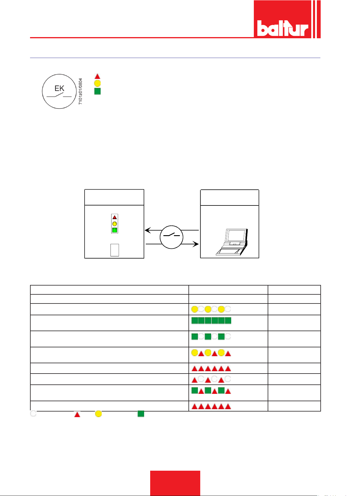
ENGLISH
7101z03e0305
CONTROL AND COMMAND EQUIPMENT LME...
OPERATION.
RED
YELLOW
GREEN
Both «LED» and «EK...» are positioned under the transparent button. Pressing this button, you can reset the control box.
Possibility of two diagnostic functions:
1. Visual indication directly on the reset button: operation and diagnostics of device status.
2. Diagnostics with interface: in this case the OCI400 connecting cable is necessary and it can be connected to a PC with ACS400 software, or to gas analysers of different manufacturers
Visual indication.
During operation, the command and control equipment phase is indicated on the reset button. The table lists all colour sequences and
their meaning. To activate the diagnostics function, hold the reset button down for at least 3 seconds. A quick red ashing indicates that
the function is active. Likewise, hold the reset button down for at least 3 seconds to deactivate the function (the switching will be indicated
with a ashing yellow light).
The reset button «EK...» is the main element to access all diagnostic functions (activation and deactivation), and serves to unlock the command
and control device.
Operating position
Diagnostics
Colour code table
xxxxxxxx
xxxxxxxx
xxxxxxxx
xxxxxxxx
xxxxxxxx
xxxxxxxx
> 3 s
EK
Operating position
PC interface/diagnostic
analyser
COMMAND AND CONTROL DEVICE STATUS INDICATION.
Condition Colour sequence Colours
Waiting conditions TW, other intermediate statuses . . . . . . . . No light
Ignition phase
Correct operation, current strength of ame detector above the mini-
Intermittent yellow
Green
mum allowed
Incorrect operation, current strength of ame detector below the mini-
Intermittent green
mum allowed
Decrease in power supply voltage
Alternating Yellow
and Red
Burner in lock condition
Red
Fault indication (see colour legend)
Extraneous light upon burner start-up
Intermittent red
Alternating Green
and Red
Quick ashing for diagnostics
Quick ashing red
NO LIGHT. RED. YELLOW. GREEN.
30 / 44
0006160003_201510
Page 77
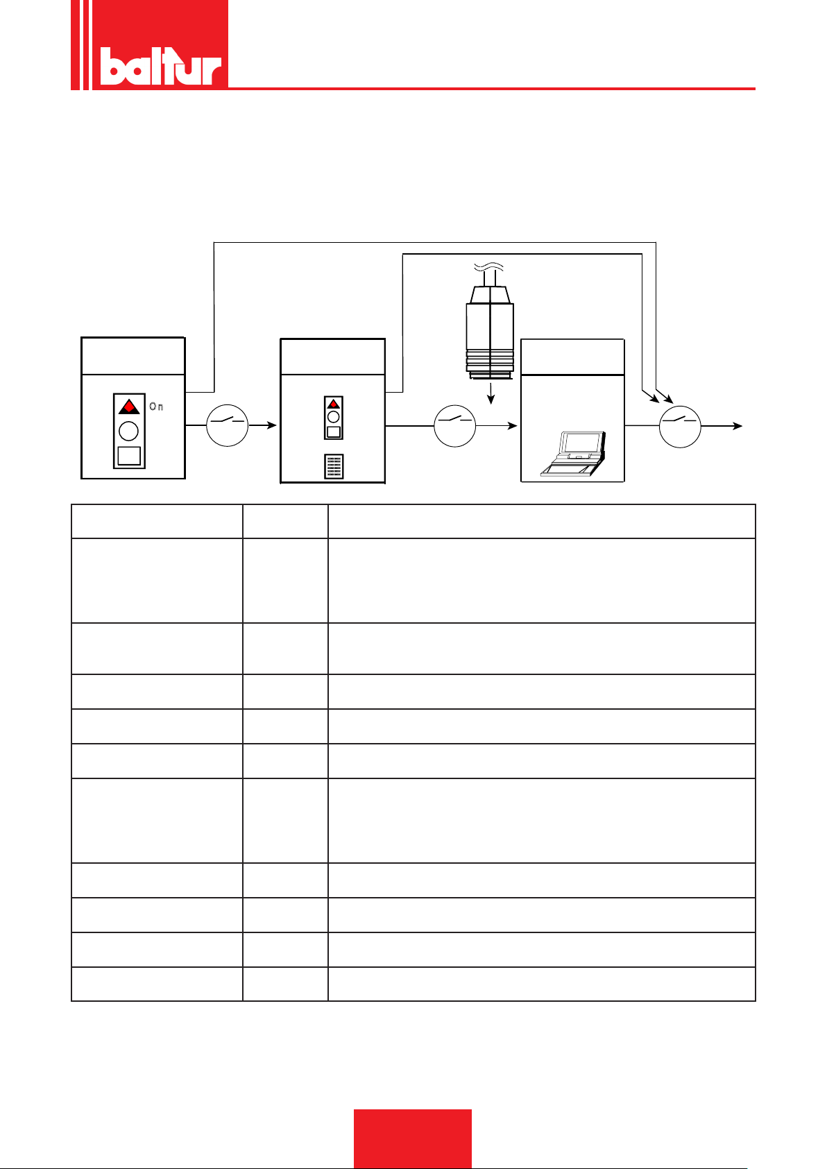
ENGLISH
E K
> 3 s
xxxxxxxx
xxxxxxxx
xxxxxxxx
xxxxxxxx
xxxxxxxx
xxxxxxxx
E K
OCI400
E K
< 3 s
7101z04e0305
R e s e t
O n
> 3 s
MALFUNCTION AND LOCK CAUSE DIAGNOSTICS.
In the event of a burner lock-out, the red light on the reset button will be xed.
Keeping it pressed in for more than 3 seconds, the diagnostics procedure is activated (red light with quick ashes). The table below indicates the meaning of the lock-out or failure according to the number of red ashes.
Holding the reset button down for at least 3 seconds, the diagnostics function will be interrupted.
The diagram below shows the operations to be carried out to activate the diagnostic functions even with communication interface through
the "OCI400" connection cable.
Operating position
Operating position
Visual indication
Colour code table
Visual indication AL to terminal 10Possible causes
2 blinks
●●
On No ame at the end of the safe ignition time<TSA>
- Faulty or soiled fuel valves
- Faulty or soiled ame detector
- Poor adjustment of burner, no fuel
- No ignition Faulty ignition transformer
3 blinks
●●●
On - Defective LP air pressure switch
- No or faulty air pressure signal after completion "t10"
- LP pressure switch contact welded in standby position
4 blinks
On Extraneous light during the ignition phase
●●●●
5 blinks
●●●●●
6 blinks
On - No air pressure switch signal
- LP pressure switch contact welded in work position
On Not used
●●●●●●
7 blinks
●●●●●●●
On No ame signal during normal operation, ignition repetition (limitation of ignition
repetitions)
- Malfunction of the fuel valves
Faulty or soiled ame detector
- Poor adjustment of burner
8 blinks
On Not used
●●●●●●●●
9 blinks
On Not used
●●●●●●●●●
10 blinks
On Wiring problems or damage inside the device
●●●●●●●●●●
14 blinks
On CPI contact not closed
●●●●●●●●●●●●●●
Operating position
PC / analyser
interface
diagnostics
• During the time the cause of fault is diagnosed, the control outputs are deactivated.
• - Is the burner shut down?
• - The alarm signal AL “is on terminal 10 which is under voltage.
• Press the lockout reset button for about 1 second (< 3 seconds) to reactivate the device and start a new cycle.
31 / 44
0006160003_201510
Page 78
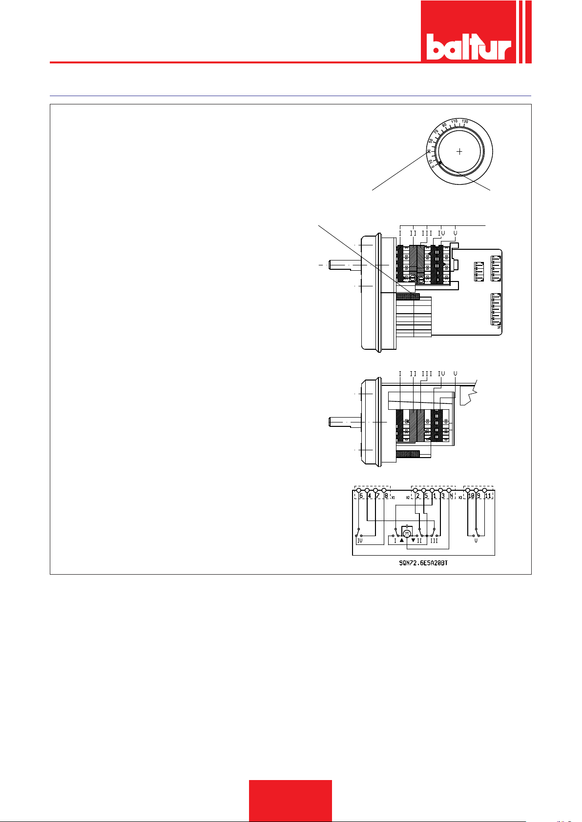
ENGLISH
SERVOMOTOR CAMS ADJUSTMENT SQN72.6E5A20BT
Use the corresponding rings to modify the adjustment of the uti-
lized cams (I - II - III....).The index of the ring indicate on the
respective reference scale the rotation angle taken up for each
cam.
0002937920
A B
A Reference scale.
B Position indicator.
C Camshaft-motor coupling enabling/disabling pin.
I Maximum air opening regulation cam (130°)
II Total air closure (burner stopped) (0°)
III Air regulation cam for minimum gas setting (30°)
IV 1st diesel ame air regulation cam (50°)
V Cam for the activation of 2nd ame diesel oil valve (greater
than cam IV) (80°)
C
D
32 / 44
0006160003_201510
Page 79

SPECIFICATIONS FOR PROPANE USE
• Operating costs approximate assessment;
- 1 m3 of liquid gas in gaseous stage has a lower heating
capacity, of nearly 25.6 kWh.
- To obtain 1 cu.m of gas, about 2 kg of liquid gas are needed,
i.e. about 4 litres of liquid gas.
• Safety provisions
• Liquid propane gas (L.P.G.) in the gaseous form has a greater
specic weight than air (specic weight relative to air = 1.56 for
propane), which means it does not disperse in air like natural
gas, which has a lower specic weight than air (specic weight
of natural gas relative to air = 0.60), but precipitates and spreads out at ground level (as if it were a liquid). Summing up the
concepts we deem most relevant for the use of LPG
• Liqueed petroleum gas (L.P.G.) burners and/or boilers may be
used only in premises located above ground level and certi-
ed toward free spaces. Installations using liquid gas are not
allowed in underground or semi-underground premises.
• The rooms in which LPG is used must be tted with adequate
ventilation slots on external walls without closing devices in accordance with the regulations in force.
• Performance of the LPG system to ensure correct and safe
operation.
Natural gasication, from a cylinder bank or tank, can be used only for systems having low power. The following table gives an approximate indication of the gas output capacity according to the tank size and minimum outdoor temperature.
ENGLISH
DANGER / CAUTION
The burner's minimum and maximum output (kW) is rated
based on its use with methane gas which more or less corresponds to the power values obtained with propane gas.
• Combustion testing
To limit consumption and avoid serious trouble, adjust combustion by using the appropriate instruments. It is absolutely essential to check that the percentage of carbon monoxide (CO) does
not exceed the maximum value permitted by the regulations in
force (use a combustion analyser).
DANGER / CAUTION
The warranty does not cover burners burning liquid gas
(L.P.G.) in installations in which these measures have not
been taken.
Minimum
tempera-
ture
990 l tank
3000 l tank
5000 l tank
- 15 °C - 10 °C - 5 °C - 0 °C + 5 °C
1.6 Kg/h 2.5 Kg/h 3.5 Kg/h 8 Kg/h 10 Kg/h
2.5 Kg/h 4.5 Kg/h 6.5 Kg/h 9 Kg/h 12 Kg/h
4 Kg/h 6.5 Kg/h
11.5
Kg/h
16 Kg/h 21 Kg/h
33 / 44
0006160003_201510
Page 80
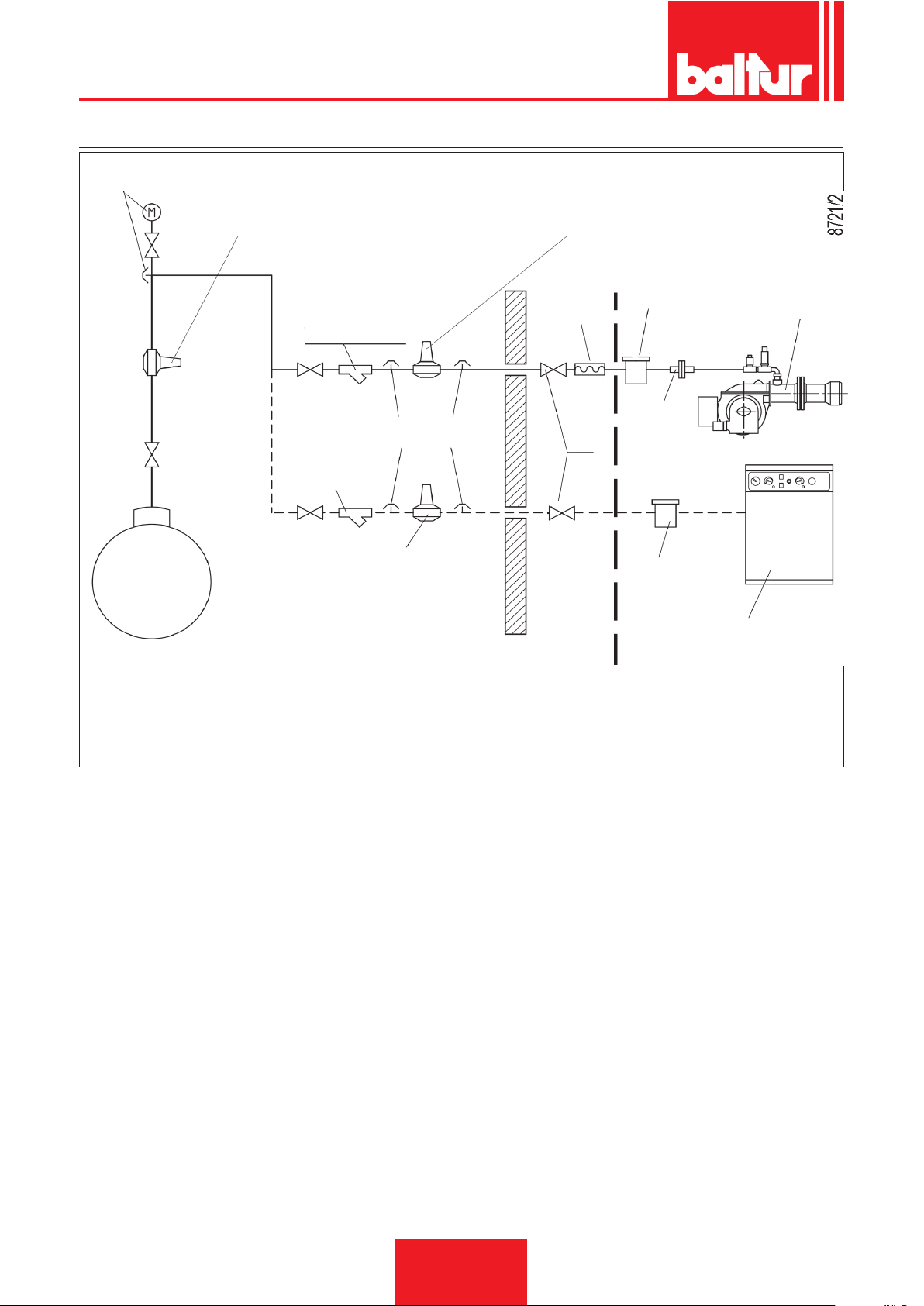
ENGLISH
DIAGRAM ILLUSTRATING THE PRINCIPLE OF L.P.G. PRESSURE REDUCTION IN TWO STAGES FOR BURNER OR BOILER
Pressure gauge and pressure
intake
1st step reducer
Output ~ 1.5 bar
Flow rate ~ double the maximum required by the
user
2nd step reducer
Output ~ 30 mbar
Flow rate ~ double the maximum required by
the user
LPG tank
Y lter
Pressure intake
Y lter
2nd step reducer
Output ~ 30 mbar
Flow rate ~ double the maximum required by
the user
RESPONSIBILITY OF THE INSTALLER
Vibration-proof
joint
Filter
Fitting
Ball cock
Filter
Free-standing or wall-mounted
boiler
SUPPLIED BY THE CUSTOMER
Burner
34 / 44
0006160003_201510
Page 81
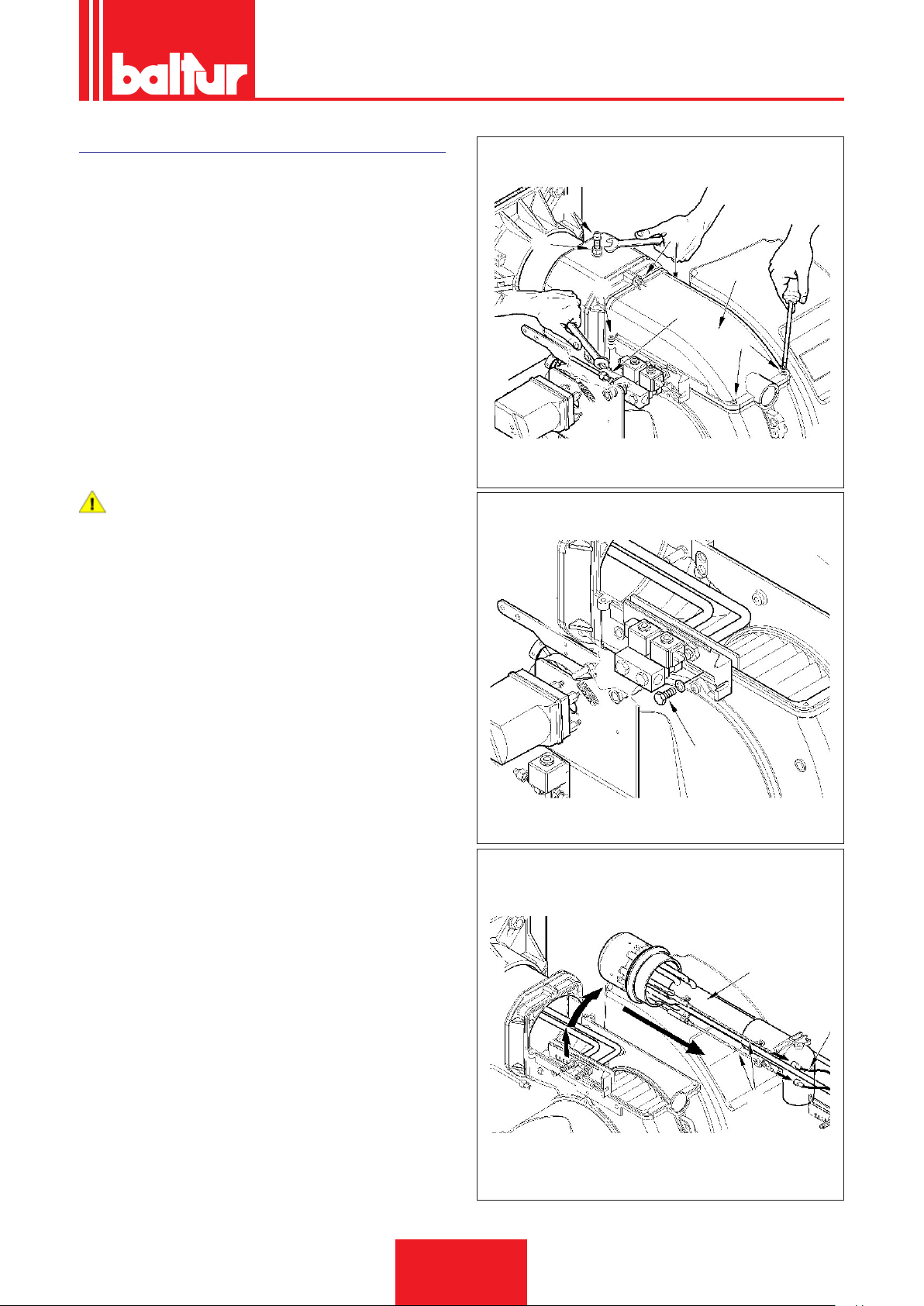
MAINTENANCE
0002937470
Analyse combustion gases and check that the emission values
are correct at least once a year, in compliance with current law.
Carry out the following operations at the end of the heating season:
• Clean air dampers, the air pressure switch with pressure port
and the relevant pipe (if tted).
• Check the electrode condition. Replace them, if necessary.
• Clean the photocell. Replace it, if necessary.
• Have the burner and the chimney cleaned by specialised per-
sonnel (stove repairer); a clean burner is more efcient, lasts
longer and is quieter.
• Check that the fuel lter is clean. Replace it, if necessary.
• Check that all components of the combustion head are in good
condition, have not been deformed and are free from deposits deriving from the installation environment and/or from poor
combustion.
• Analyse combustion gases and check emissions values.
DANGER / CAUTION
When closing the burner, gently pull the two ignition cables
towards the electrical panel, putting them slightly in tension,
then arrange them in their housing on the scroll. This will
ensure that the two cables do not get damaged by the fan
during burner operation.
If it is necessary to clean the outside of the combustion head, take
out its components according to the procedure described:
• Disconnect the photocell and the air pressure switch pipe from
the upper lid of the burner.
• Disconnect diesel fuel pipe -24 from its connector (be careful
of drips).
• Loosen screws 5 -6 and remove the cover -11 .
• After having loosened the nut -9 remove the locking screw (32)
of the mixer unit.
• Remove the screw -16 and its washer placed on the outside of
the burner scroll.
• Slightly lift the mixing unit -17, and then completely pull out the
unit in the direction indicated by the arrow, after removing the
ignition cables -10 from the respective electrodes.
• After completing the maintenance operations proceed with the
assembly of the mixing unit by carrying out the above operations in reverse order, after checking that the ignition electrodes
and the deector disk are correctly positioned.
9
0002937480
ENGLISH
32
6
11
6
24
6
16
17
35 / 44
0006160003_201510
Page 82
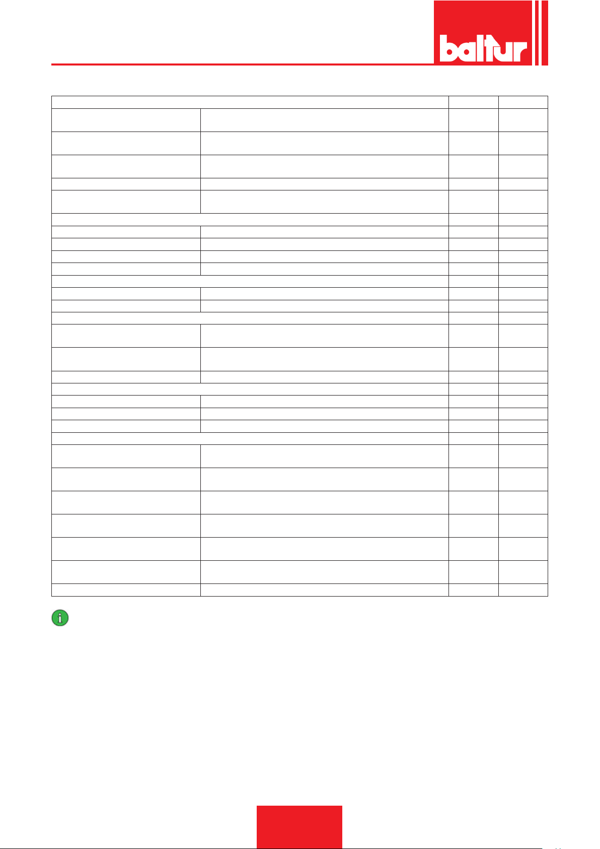
ENGLISH
MAINTENANCE TIME
COMBUSTION HEAD GAS DIESEL
ELECTRODES
FLAME DISK
COMBUSTION HEAD COMPONENTS
LIQUID FUEL NOZZLES REPLACEMENT N.A. YEARLY
INSULATING SEAL
AIR SHUTTER BEARINGS GREASING, (NOTE: apply only to burners with bearings to be greased) 6 MONTHS 6 MONTHS
AIR FAN CLEANING YEAR YEAR
AIR PRESSURE SWITCH CLEANING YEAR YEAR
AIR PRESSURE PIPES AND OUTLET CLEANING YEAR YEAR
FLAME SENSOR CLEANING YEAR YEAR
GAS PRESSURE SWITCH OPERATIONAL TEST YEAR YEAR
ELECTRIC MOTORS (BEARINGS/COO-
LING FAN)
LEVERS/STRAP SYSTEM/BALL JOINTS
(BACKLASH/LUBRICATION)
HOSES REPLACEMENT N.A. 5 YEARS
PUMP FILTER CLEANING YEAR YEAR
LINE FILTER CLEANING/REPLACEMENT (SPARE CARTRIDGE?) YEAR YEAR
GAS FILTER REPLACE THE FILTER YEAR YEAR
CO TEST
CO2 TEST
TEST OF FUMES ACCORDING TO
BACHARACH INDEXES
NOX TEST
IONISATION CURRENT TEST
FUME TEMPERATURE TESTING
GAS PRESSURE REGULATOR PRESSURE MEASUREMENT UPON START-UP YEAR N.A.
VISUAL INSPECTION OF THE INTEGRITY OF CERAMICS. TIP GRIN-
DING, CHECK DISTANCE, CHECK ELECTRICAL CONNECTION.
INTEGRITY VISUAL INSPECTION FOR POSSIBLE WARPING, CLEA-
NING
INTEGRITY VISUAL INSPECTION FOR POSSIBLE WARPING, CLEA-
NING
VISUAL INSPECTION OF LEAK TIGHTNESS AND POSSIBLE REPLA-
CEMENT
AIR LINE GAS DIESEL
SAFETY COMPONENTS GAS DIESEL
VARIOUS COMPONENTS GAS DIESEL
CLEANING, (see if the supplier's indications were provided) YEAR YEAR
CHECK FOR POSSIBLE BACKLASH YEAR YEAR
FUEL LINE GAS DIESEL
COMBUSTION PARAMETERS GAS DIESEL
COMPARISON WITH THE VALUES RECORDED UPON THE EQUIP-
MENT START-UP
COMPARISON WITH THE VALUES RECORDED UPON THE EQUIP-
MENT START-UP
COMPARISON WITH THE VALUES RECORDED UPON THE EQUIP-
MENT START-UP
COMPARISON WITH THE VALUES RECORDED UPON THE EQUIP-
MENT START-UP
COMPARISON WITH THE VALUES RECORDED UPON THE EQUIP-
MENT START-UP
COMPARISON WITH THE VALUES RECORDED UPON THE EQUIP-
MENT START-UP
YEARLY YEARLY
YEARLY YEARLY
YEARLY YEARLY
YEARLY YEARLY
YEAR YEAR
YEAR YEAR
YEAR YEAR
YEAR YEAR
YEAR YEAR
YEAR YEAR
IMPORTANT
In case of heavy use or particular fuels, the maintenance frequency must be increased and adapted to the use conditions according
to the maintenance technician's indications.
36 / 44
0006160003_201510
Page 83

NOZZLE FLOW RATE TABLE
ENGLISH
Nozzle
output
ow-rate
G.P.H. Nozzle output ow-rate G.P.H.
0,40 1,27 1,36 1,44 1,52 1,59 1,67 1,73 1,80 1,86 1,92 1,98 2,04 2,10 2,15 2 0,40
0,50 1,59 1,70 1,80 1,90 1,99 2,08 2,17 2,25 2,33 2,40 2,48 2,55 2,62 2,69 2,75 0,50
0,60 1,91 2,04 2,16 2,28 2,39 2,50 2,60 2,70 2,79 2,88 2,97 3,06 3,14 3,22 3,30 0,60
0,65 2,07 2,21 2,34 2,47 2,59 2,71 2,82 2,92 3,03 3,12 3,22 3,31 3,41 3,49 3,58 0,65
0,75 2,38 2,55 2,70 2,85 2,99 3,12 3,25 3,37 3,49 3,61 3,72 3,82 3,93 4,03 4,13 0,75
0,85 2,70 2,89 3,06 3,23 3,39 3,54 3,68 3,82 3,96 4,09 4,21 4,33 4,45 4,57 4,68 0,85
1,00 3,18 3,40 3,61 3,80 3,99 4,16 4,33 4,50 4,65 4,81 4,96 5,10 5,24 5,37 5,51 1,00
1,10 3,50 3,74 3,97 4,18 4,38 4,58 4,77 4,95 5,12 5,29 5,45 5,61 5,76 5,91 6,06 1,10
1,20 3,82 4,08 4,33 4,56 4,78 5,00 5,20 5,40 5,59 5,77 5,95 6,12 6,29 6,45 6,61 1,20
1,25 3,97 4,25 4,50 4,75 5,00 5,20 5,40 5,60 5,80 6,00 6,20 6,35 6,55 6,70 6,85 1,25
1,35 4,29 4,59 4,87 5,13 5,38 5,62 5,85 6,07 6,28 6,49 6,69 6,88 7,07 7,26 7,44 1,35
1,50 4,77 5,10 5,41 5,70 5,90 6,24 6,50 6,75 6,98 7,21 7,43 7,65 7,86 8,06 8,26 1,50
1,65 5,25 5,61 5,95 6,27 6,58 6,87 7,15 7,42 7,68 7,93 8,18 8,41 8,64 8,87 9,09 1,65
1,75 5,56 5,95 6,31 6,65 6,98 7,29 7,58 7,87 8,15 8,41 8,67 8,92 9,17 9,41 9,64 1,75
2,00 6,30 6,80 7,21 7,60 7,97 8,33 8,67 8,99 9,31 9,61 9,91 10,20 10,48 10,75 11,01 2,00
2,25 7,15 7,65 8,15 8,55 8,97 9,37 9,75 10,12 10,47, 10,85 11,15 11,47 11,79 12,09 12,39 2,25
2,50 7,95 8,50 9,01 9,50 9,97 10,41 10,83 11,24 11,64 12,02 12,39 12,75 13,10 13,44 13,77 2,50
3,00 9,54 10,20 10,82 11,40 11,96 12,49 13,00 13,49 13,96 14,02 14,87 15,30 15,72 16,12 16,52 3,00
3,50 11,13 11,90 12,62 13,30 13,95 14,57 15,17 15,74 16,29 16,83 17,34 17,85 18,34 18,81 19,28 3,50
4,00 12,72 13,60 14,42 15,20 15,94 16,65 17,33 17,99 18,62 19,23 19,82 20,40 20,95 21,50 22,03 4,00
4,50 14,31 15,30 16,22 17,10 17,94 18,73 19,50 20,24 20,95 21,63 22,30 22,95 23,57 24,19 24,78 4,50
5,00 15,90 17,00 18,03 19,00 19,93 20,82 21,67 22,48 23,27 24,04 24,78 25,49 26,19 26,87 27,54 5,00
5,5
6,00 19,00 20,40 21,63 22,80 23,92 24,98 26,00 26,98 27,93 28,84 29,73 30,59 31,43 32,25 33,04 6,00
6,50 20,67 22,10 23,44 23,70 25,91 27,06 28,17 29,23 30,26 31,25 32,21 33,14 34,05 34,94 35,80 6,50
7,00 22,26 23,79 25,24 26,60 27,60 29,14 30,33 31,48 32,58 33,65 34,69 35,69 36,67 37,62 38,55 7,00
7,50 23,85 25,49 27,04 28,50 29,90 31,22 32,50 33,73 3491 36,05 37,16 38,24 39,29 40,31 41,31 7,50
8,30 26,39 28,21 29,93 31,54 33,08 34,55 35,97 37,32 38,63 39,90 41,13 42,32 43,48 44,61 45,71 8,30
9,50 30,21 32,29 34,25 36,10 37,87 39,55 41,17 42,72 44,22 45,67 47,07 48,44 48,77 51,06 52,32 9,5
10,50 33,39 35,69 37,86 40,06 41,73 43,74 45,41 47,20 48,90 50,50 52,00 53,50 55,00 56,40 57,80 10,50
12,00 38,20 40,80 43,30 45,60 47,80 50,00 52,00 54,00 55,90 57,70 59,50 61,20 62,90 64,50 66,10 12,00
13,80 43,90 46,90 49,80 52,40 55,00 57,50 59,80 62,10 64,20 66,30 68,40 70,40 72,30 74,30 76,00 13,80
15,30 48,60 52,00 55,20 58,10 61,00 63,70 66,30 68,80 71,10 73,60 75,80 78,00 80,20 82,20 84,30 15,30
17,50 55,60 59,50 63,10 66,50 69,80 72,90 75,80 78,70 81,50 84,10 86,70 89,20 91,70 94,10 96,40 17,50
19,50 62,00 66,30 70,30 74,10 77,70 81,20 84,50 87,70 90,80 93,70 96,60 99,40
21,50 68,40 73,10 77,50 81,70 85,70 89,50 93,20 96,70
24,00 76,30 81,60 86,50 91,20 95,70 99,90
28,00 89,00 95,20
30,00 95,40
7 8 9 10 11 12 13 14 15 16 17 18 19 20 21
17,49 18,70 19,83 20,90 21,92 22,90 23,83 24,73 25,6 26,44 27,25 28,04 28,81 29,56 30,29 5,5
101,00 106,40
102,00 108,20
111,60
114,00 119,60
116,60
124,90 130,00 134,90 139,90 144,20 148,70 153,00 157,20 161,20 165,20
Pump Nozzle
102,20 104,80 107,40
100,10 103,40 106,50 109,60
104,00 107,90
121,30 125,90 130,30 134,60 138,70 142,80 146,70 150,50 154,20
11,70
115,40 118,90
112,60 115,60 118,40
122,40 125,70 129,00
132,20
output
ow-rate
19,50
21,50
24,00
28,00
30,00
1 mbar = 10 mmCA = 100 Pa
1 kW = 860 kcal
Diesel density =0.820 / 0.830 PCI = 10150
Fuel oil density (3.5° E) = 0.940 PCI = 9700
Heavy fuel oil density (7,9° E) = 0.970/0.980 PCI = 9650
PCI Lower Caloric Value
37 / 44
0006160003_201510
Page 84

ENGLISH
TROUBLESHOOTING INSTRUCTIONS
ANOMALY
The burner does not start
up.(The equipment does not
perform the start up program).
Poor ame, with sparks.
POSSIBLE CAUSE
1 Thermostats (boiler or room) or
pressure switches are open.
2 Photoresistant-cell in short circuit.
3 Absence of line voltage, main switch
open, meter switch tripped or absen-
ce of line voltage.
4 Thermostat line not wired according
to diagram or open thermostats.
5 Equipment internal fault.
1 Spraying pressure is too low.
2 Too much combustion air.
3 Nozzle inefcient because dirty or
worn.
4 Water in the fuel.
REMEDY
1 Raise the thermostats settings, or
wait that the contacts close for natural
decrease of temperature or pressure.
2 Replace it.
3 Activate switches or wait for power to
return.
4 Check the connections and thermosta-
ts.
5 Replace it.
1 Restore it at the required value.
2 Reduce combustion air
3 Clean or replace.
4 Drain water from the tank using a sui-
table pump. Never use the burner pump
for this purpose.
Poorly shaped ame with
smoke and soot.
Defective ame, ickering or
protruding from combustion
head.
1 Insufcient combustion air ow.
2 Nozzle inefcient because dirty or
worn.
3 Nozzle capacity too low with respect
to combustion chamber volume.
4 Combustion chamber unsuitably
designed or too small.
5 Unsuitable refractory coating (it
reduces excessively the space of the
ame).
6 Boiler or chimney ducts blocked.
7 Spraying pressure is low.
1 Excessive draught, only when there
is an extractor in the chimney.
2 Nozzle inefcient because dirty or
worn.
3 Water in the fuel.
4 Dirty deector disk.
5 Too much combustion air.
6 Air passage between deector disk
and diffuser excessively closed.
1 Increase combustion air.
2 Clean or replace.
3 Decrease diesel ow rate to suit the
chamber (thermal power will obviously
be lower than necessary) or replace the
boiler.
4 Increase nozzle ow by replacing it.
5 Modify it, carefully abiding by the in-
structions given by boiler manufacturer.
6 Arrange for cleaning.
7 Restore it at the required value.
1 Adjust the suction fan speed by chan-
ging the pulley diameter.
2 Clean or replace.
3 Drain water from the tank using a sui-
table pump. Never use the burner pump
for this purpose.
4 Clean.
5 Reduce combustion air.
6 Correct the position of the combustion
head regulating device.
38 / 44
0006160003_201510
Page 85

ENGLISH
ANOMALY
Corrosion inside the boiler.
Soot at the mouth of the chimney.
POSSIBLE CAUSE
1 Boiler operating temperature too
low (below the dew point).
2 Smoke temperature too low,
approximately below 130 °C for
diesel.
1 Excessive cooling of smoke
(approximately below 130°C) in the
chimney, for an outside chimney not
adequately heat insulated or cold
air inltration.
REMEDY
1 Increase the operating temperature.
2 Increase diesel ow rate is the boiler
allows it.
1 Improve insulation and close any ope-
ning letting cold air into the chimney.
The burner goes into lock-out (red
light on). The fault is in the ame
control device.
The burner goes to shut down
spraying liquid fuel but without ame presence (red light on).
The trouble is in the ignition device, providing the fuel is not polluted
with water or other impurities and
sufciently atomised.
The equipment goes into “lock-
out”, gas ows out, but there is no
ame (red light on). Fault in ignition
circuit.
1 Photoresistance severed or fouled
with smoke.
2 Insufcient draught.
3 Flame detector circuit interrupted in
the equipment.
4 Dirty deector disk and diffuser.
1 Ignition circuit severed.
2 The ignition transformer cables are
discharging to ground.
3 The ignition transformer cables are
not well connected.
4 Ignition transformer is faulty.
5 The electrode faces are not at the
right distance.
6 Electrodes discharge to earth
because they are dirty or their
insulation is cracked: check also
the porcelain insulator terminals.
1 Clean or replace.
2 Check all the smoke ducts in the boiler
and in the chimney.
3 Replace the equipment.
4 Clean.
1 Check the entire circuit.
2 Replace.
3 Restore the connection.
4 Replace.
5 Return to the required position.
6 Clean and if necessary replace them.
39 / 44
0006160003_201510
Page 86

ENGLISH
ANOMALY
The burner goes to shut down
spraying liquid fuel but without ame presence. (Red light on).
POSSIBLE CAUSE
1 Pump pressure is not regular.
2 Water in the fuel.
3 Too much combustion air.
4 Air passage between deector disk
and diffuser excessively closed.
5 Nozzle worn out or dirty.
REMEDY
1 Adjust.
2 Drain water from the tank using a
suitable pump. Never use the burner
pump for this purpose.
3 Reduce combustion air.
4 Correct the position of the combustion
head adjusting device.
5 Clean or replace.
The burner goes into “lock-out”,
gas ows, but there is no ame
(red light on).
Noisy burner pump.
1 Air - gas ratio incorrect.
2 Gas pipe has not been properly
bled of air at the rst ignition.
3 The gas pressure is insufcient or
excessive.
4 Air passage between deector disk
and diffuser too closed.
1 Pipe diameter too small.
2 Air inltration in the pipes.
3 Dirty fuel lter.
4 Excessive distance and/or differen-
ce in level between the tank and
the burner or numerous accidental
leakages (elbows, curves, bottlenecks, etc.)
5 Deteriorated exible pipes.
1 Correct the air - gas ratio.
2 Bleed the gas pipe again, with due
caution.
3 Check the maximum gas pressure va-
lue at the time of ignition (use a water
pressure gauge, if possible).
4 Adjust the deector disk - diffuser.
1 Replace it according to the in-
structions.
2 Check and eliminate inltrations.
3 Remove and wash.
4 Adjust the length of the suction pipe to
reduce the distance.
5 Replace.
40 / 44
0006160003_201510
Page 87
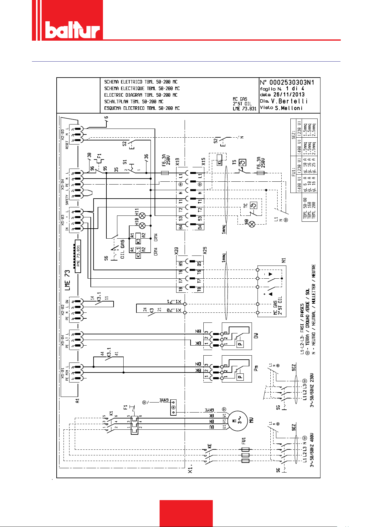
WIRING DIAGRAMS
ENGLISH
41 / 44
0006160003_201510
Page 88
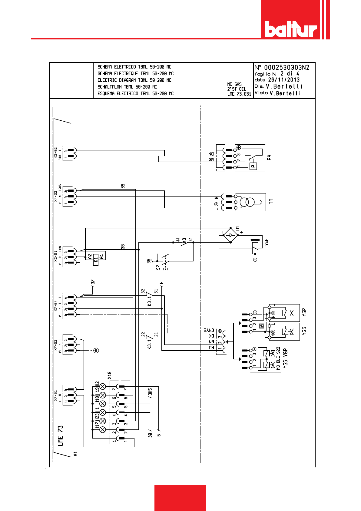
ENGLISH
42 / 44
0006160003_201510
Page 89
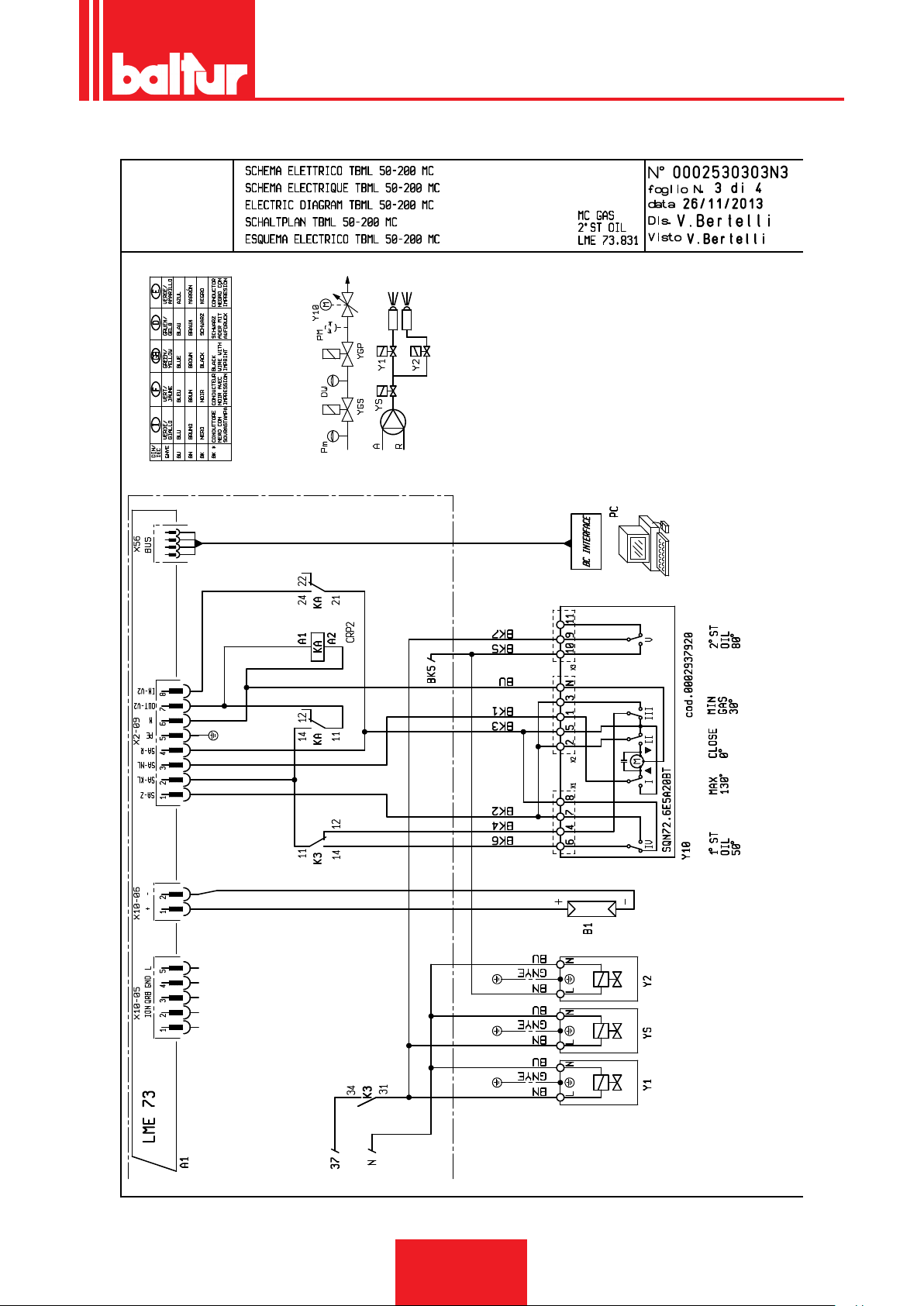
ENGLISH
43 / 44
0006160003_201510
Page 90

ENGLISH
A1 EQUIPMENT
B1 PHOTORESISTOR / IONISATION ELECTRODE / UV
PHOTOCELL
DW VALVE SEAL CONTROL PRESSURE SWITCH
F1 THERMAL RELAY
FU1÷4 FUSES
H0 EXTERNAL LOCK INDICATOR LIGHT/ AUXILIARY
HEATING ELEMENT OPERATION LAMP
H1 OPERATION INDICATOR LIGHT
H2 “LOCK-OUT INDICATOR LIGHT“
H10 “OIL WARNING LIGHT"
H11 "GAS WARNING LIGHT"
H17 FAN OPERATION INDICATOR LIGHT
H18 “2ND STAGE OPERATION INDICATOR LIGHT“
H19 MAIN VALVE OPERATION INDICATOR LIGHT
H23 TRANSFORMER OPERATION INDICATOR LIGHT
K1 FAN MOTOR CONTACTOR
K3 “CYCLIC MOTOR AUXILIARY RELAY“
K7.1 KA / KB AUXILIARY RELAY
KE EXTERNAL CONTACTOR
MV FAN MOTOR
N1 ELECTRONIC REGULATOR
PA AIR PRESSURE SWITCH
Pm “MINIMUM PRESSURE SWITCH“
S1 START/STOP SWITCH
S2 RELEASE BUTTON
S6 FUEL SWITCH
S7 TANK /SYSTEM FILLING BUTTON
SG MAIN SWITCH
TA IGNITION TRANSFORMER
TC BOILER THERMOSTAT
TS SAFETY THERMOSTAT
U1 BRIDGE RECTIFIER
X1B/S POWER SUPPLY CONNECTOR
X2B/S 2nd STAGE CONNECTOR
X18 SYNOPTIC CONNECTOR
Y1/Y2 1st / 2nd STAGE SOLENOID VALVES
YS SAFETY SOLENOID VALVE
Y10 AIR SERVOMOTOR
YEF ELECTRIC-CLUTCH
YGP MAIN GAS SOLENOID VALVE
YGS SAFETY GAS SOLENOID VALVE
44 / 44
0006160003_201510
Page 91

Page 92

BALTUR S.P.A.
Via Ferrarese, 10
44042 Cento (Fe) - Italy
Tel. +39 051-6843711
Fax. +39 051-6857527/28
www.baltur.it
Il presente catalogo riveste carattere puramente indicativo. La casa, pertanto, si riserva ogni possibilità di modica dei dati tecnici e di quant'altro in esso riportato.
Information contained in this catalogue is not binding. The manufacturer reserves the right to change the technical data and any other data it contains.
 Loading...