

Page 1

Manuale
istruzioni per l’uso
UK
Manual user instructions.
TBML 80 MC
TBML 120 MC
TBML 160 MC
TBML 200 MC
- BRUCIATORI MISTI GAS / GASOLIO A DUE STADI
PROGRESSIVI / MODULANTI
- DUAL FUEL GAS / LIGHT OIL TWO-STAGE PROGRESSIVE
/ MODULATING BURNERS
ISTRUZIONI ORIGINALI (IT)
0006081544_201408
Page 2

Page 3
• Prima di iniziare a usare il bruciatore leggere attentamente quanto esposto nell’ouscolo “AVVER TENZE PER L’UTENTE, PER L ’USO IN
Dichiariamo che i nostri bruciatori ad aria soffiata di combustibili liquidi, gassosi
e misti, domestici e industriali, serie:
BPM...; BGN…; BT…; BTG…; BTL…; TBML...; Comist…; GI…; GI…Mist;
Minicomist…; PYR…; RiNOx…; Spark...; Sparkgas...; TBG...;TBL...; TS…;
IBR...; IB...
(Variante: … LX, per basse emissioni NOx)
rispettano i requisiti minimi imposti dalle Direttive Europee:
• 2009/142/CE (D.A.G.)
• 2004/108/CE (C.E.M.)
• 2006/95/CE (D.B.T.)
• 2006/42/CE (D.M.)
e sono conformi alle Norme Europee:
• EN 676:2003+A2:2008 (gas e misti, lato gas)
• EN 267:2009 (gasolio e misti, lato gasolio)
Cento, 23 Luglio 2013
CE0085:
DVGW CERT GmbH, Josef-Wirmer Strasse 1-3 – 53123 Bonn (D)
Dichiarazione di Conformità
Amministratore Delegato
e Direttore Generale
Riccardo dr. Fava
Direttore Ricerca & Sviluppo
Paolo ing. Bolognin
SICUREZZA DEL BRUCIA TORE” presente a corredo del manuale istruzioni, che costituisce parte integrante ed essenziale del prodotto.
• Leggere attentamente le istruzioni prima di mettere in funzione il bruciatore o di eseguire la manutenzione.
• I lavori sul bruciatore e sull’impianto devono essere eseguiti solo da personale qualicato.
• L’alimentazione elettrica dell’impianto deve essere disinserita prima di iniziare i lavori. Se i lavori non sono eseguiti correttamente si
rischiano incidenti pericolosi.
ITALIANO
PERICOLO
AVVERTENZE ATTENZIONE
INFORMAZIONI
1 / 36
0006081544_201408
Page 4

ITALIANO
CARATTERISTICHE TECNICHE .....................................................................................................................................................................................5
APPLICAZIONE DEL BRUCIATORE ALLA CALDAIA
LINEA DI ALIMENTAZIONE GAS
LINEA DI ALIMENTAZIONE GASOLIO
PARTICOLARI POMPA SUNTEC
COLLEGAMENTI ELETTRICI
APPARECCHIATURA DI COMANDO E CONTROLLO PER BRUCIATORI A GAS LME 73...
DESCRIZIONE DEL FUNZIONAMENTO CON COMBUSTIBILE LIQUIDO
PRIMO RIEMPIMENTO TUBAZIONE
ACCENSIONE E REGOLAZIONE
DESCRIZIONE DEL FUNZIONAMENTO CON COMBUSTIBILE GASSOSO
DESCRIZIONE DEL FUNZIONAMENTO DELLA MODULAZIONE
ACCENSIONE E REGOLAZIONE A GAS METANO
REGOLAZIONE DELL’ ARIA SULLA TESTA DI COMBUSTIONE
SERVOMOTORI REGOLAZIONE ARIA / COMBUSTIBILE
MANUTENZIONE
ISTRUZIONI PER L’ACCERTAMENTO DELLE CAUSE DI IRREGOLARITÀ’ NEL FUNZIONAMENTO E LORO ELIMINAZIONE
SCHEMA ELETTRICO
............................................................................................................................................................................................................26
.....................................................................................................................................................................................................31
.....................................................................................................................................................................................10
............................................................................................................................................................................11
....................................................................................................................................................................................14
..........................................................................................................................................................................................15
..............................................................................................................................................................................19
..................................................................................................................................................................................19
......................................................................................................................................................8
........................................................................................16
....................................................................................................................17
.................................................................................................................21
.................................................................................................................................21
........................................................................................................................................................22
...................................................................................................................................24
.............................................................................................................................................25
...............................28
2 / 36
0006081544_201408
Page 5

PREMESSA
Queste avvertenze si propongono di contribuire alla sicurezza nella
utilizzazione dei componenti per impianti di riscaldamento ad uso civile e
produzione di acqua calda per uso sanitario, mediante l’indicazione di quei
comportamenti che é necessario od opportuno adottare al ne di evitare
che le loro originarie caratteristiche di sicurezza risultino compromesse
da eventuali installazioni non corrette, usi erronei, impropri o irragionevoli.
La diffusione delle avvertenze fornite da questa guida mira anche alla
sensibilizzazione del pubblico dei “consumatori” ai problemi della sicurezza
mediante un linguaggio necessariamente tecnico ma facilmente accessibile.
E’ esclusa qualsiasi responsabilità contrattuale ed extracontrattuale del
costruttore per i danni causati da errori nell’installazione e nell’uso, e
comunque da inosservanza delle istruzioni date dal costruttore stesso.
AVVERTENZE GENERALI
• ll libretto di istruzioni costituisce parte integrante ed essenziale del
• L’installazione dell’apparecchio deve essere effettuata in ottemperanza
• Dopo aver tolto ogni imballaggio assicurarsi dell’integrità del contenuto.
• Prima di effettuare qualsiasi operazione di pulizia o di manutenzione,
• In caso di guasto e/o di cattivo funzionamento dell’apparecchio, disattivarlo,
• Se l’apparecchio dovesse essere venduto o trasferito ad un altro
• Per tutti gli apparecchi con optionals o kit (compresi quelli elettrici) si
: applicato a caldaie, generatori di aria calda,
forni o altri focolari simili, situati in luogo riparato dagli agenti atmosferici.
• ll bruciatore deve essere installato in un locale adatto con aperture
minime di ventilazione secondo quanto prescritto dalle norme vigenti e
• Non ostruire né ridurre la sezione delle griglie di aspirazione dell’aria
del bruciatore, e le aperture di aerazione del locale dove é installato un
bruciatore o una caldaia, per evitare che si creino situazioni pericolose
• Prima di collegare il bruciatore accertarsi che i dati di targa siano
corrispondenti a quelli della rete di alimentazione (elettrica, gas, gasolio
vicinanza della amma e dell’eventuale sistema di preriscaldamento del
combustibile, diventano calde durante il funzionamento e permangono
Disinserire l’alimentazione elettrica staccando il cavo di alimentazione
Chiudere l’alimentazione del combustibile attraverso la valvola manuale
di intercettazione e asportare i volantini di comando dalla loro sede.
Rendere innocue quelle parti che potrebbero essere potenziali fonti
• Accertarsi che, chi ha eseguito l’installazione del bruciatore, lo abbia
Tarare la portata di combustibile del bruciatore secondo la potenza
Regolare la portata d’aria comburente per ottenere un valore di
rendimento combustione almeno pari al minimo imposto dalle norme
Eseguire il controllo della combustione onde evitare la formazione di
incombusti nocivi o inquinanti oltre i limiti consentiti dalle norme vigenti.
Veri care la funzionalità dei dispositivi di regolazione e di sicurezza.
Controllare al termine delle regolazioni che tutti i sistemi di bloccaggio
Accertarsi che nel locale caldaia siano presenti le istruzioni relative
• In caso di ripetuti arresti in blocco del bruciatore non insistere con le
procedure di riarmo manuale, ma rivolgersi a personale professionalmente
da personale professionalmente qualificato, in ottemperanza alle
AVVERTENZE PER L’USO IN CONDIZIONI DI SICUREZZA
BRUCIATORI
• Questo apparecchio dovrà essere destinato solo all’uso per il quale é stato
espressamente previsto
prodotto e dovrà essere consegnato all’utente. Leggere attentamente
le avvertenze contenute nel libretto in quanto forniscono importanti indicazioni riguardanti la sicurezza di installazione, d’uso e manutenzione.
Conservare con cura il libretto per ogni ulteriore consultazione.
alle norme vigenti, secondo le istruzioni del costruttore a da personale pro-
fessionalmente quali cato. Per personale professionalmente quali cato si
intende quello avente competenza tecnica nel settore dei componenti di
impianti di riscaldamento ad uso civile e produzione di acqua calda ad uso
sanitario e, in particolare, i centri assistenza autorizzati dal costruttore.
Un’errata installazione può causare danni a persone, animali o cose, per
i quali il costruttore non é responsabile.
In caso di dubbio non utilizzare l’apparecchio e rivolgersi al fornitore.
Gli elementi dell’imballaggio (gabbia di legno, chiodi, graffe, sacchetti di
plastica, polistirolo espanso, ecc.) non devono essere lasciati alla portata
dei bambini in quanto potenziali fonti di pericolo. Inoltre, onde evitare
inquinamento, vanno raccolti e depositati in luoghi predisposti allo scopo.
disinserire l’apparecchio dalla rete di alimentazione agendo sull’interruttore
dell’impianto e/o attraverso gli appositi organi di intercettazione.
astenendosi da qualsiasi tentativo di riparazione o di intervento diretto.
Rivolgersi esclusivamente a personale professionalmente quali cato.
L’eventuale riparazione dei prodotti dovrà essere effettuata solamente
da un centro di assistenza autorizzato dalla BALTUR utilizzando
esclusivamente ricambi originali. Il mancato rispetto di quanto sopra, può
compromettere la sicurezza dell’apparecchio. Per garantire l’ef cienza
dell’ apparecchio e per il suo corretto funzionamento é indispensabile fare
effettuare da personale professionalmente quali cato la manutenzione
periodica attenendosi alle indicazioni fornite dal costruttore.
proprietario o se si dovesse traslocare e lasciare l’apparecchio,
assicurarsi sempre che il libretto accompagni l’apparecchio in modo che
possa essere consultato dal nuovo proprietario e/o dall’installatore.
dovranno utilizzare solo accessori originali.
Ogni altro uso é da considerarsi improprio e quindi pericoloso.
comunque suf cienti per ottenere una perfetta combustione
come la formazione di miscele tossiche ed esplosive.
o altro combustibile).
• Non toccare parti calde del bruciatore. Queste, normalmente situate in
tali anche dopo un arresto non prolungato del bruciatore.
• Allorché si decide di non utilizzare, in via de nitiva il bruciatore, si
dovranno far effettuare da personale professionalmente quali cato le
seguenti operazioni:
a)
dell’interruttore generale.
b)
c)
di pericolo.
Avvertenze particolari
ssato saldamente al generatore di calore in modo che la amma si
generi all’interno della camera di combustione del generatore stesso.
• Prima di avviare il bruciatore e almeno una volta all’anno, far effettuare
da personale professionalmente quali cato le seguenti operazioni:
a)
richiesta dal generatore di calore.
b)
vigenti.
c)
d)
e) Veri care la corretta funzionalità del condotto di evacuazione dei
prodotti della combustione.
f)
meccanico dei dispositivi di regolazione siano ben serrati.
g)
all’uso e manutenzione del bruciatore.
quali cato per ovviare a tale situazione anomala.
• La conduzione e la manutenzione devono essere effettuate esclusivamente
disposizioni vigenti.
ITALIANO
3 / 36
0006081544_201408
Page 6

ALIMENTAZIONE ELETTRICA
•
La sicurezza elettrica dell’apparecchio è raggiunta soltanto quando lo
•
•
•
•
•
•
•
•
ALIMENTAZIONE CON GAS, GASOLIO, O ALTRI COMBUSTIBILI
Avvertenze generali
•
•
•
b) la regolazione della portata del combustibile secondo la potenza
c) che il bruciatore sia alimentato dal tipo di combustibile per il quale
d) che la pressione di alimentazione del combustibile sia compresa
e) che l’impianto di alimentazione del combustibile sia dimensionato
per la portata necessaria al bruciatore e che sia dotato di tutti i
Allorché si decida di non utilizzare il bruciatore per un certo periodo,
a) che la linea di adduzione e la rampa siano conformi alle norme
Non utilizzare i tubi del gas come messa a terra di apparecchi elettrici.
Non lasciare l’apparecchio inutilmente inserito quando, lo stesso non
In caso di assenza prolungata dell’utente dell’apparecchio chiudere il
a) non azionare interruttori elettrici, il telefono e qualsiasi altro oggetto
b) aprire immediatamente porte e finestre per creare una corrente
d) chiedere l’intervento di personale professionalmente qualificato.
Non ostruire le aperture di aerazione del locale dove é installato un
apparecchio a gas, per evitare situazioni pericolose quali la formazione
E’ opportuno precisare che le caldaie ad alto rendimento e simili scaricano
nel camino i prodotti della combustione (fumi) a temperatura relativamente
bassa. Nella condizione sopra esposta i tradizionali camini, comunemente
dimensionati (sezione ed isolamento termico) possono non essere adatti per
funzionare correttamente perché il sensibile raffreddamento che i prodotti
della combustione subiscono nel percorrere gli stessi consente, molto
probabilmente, un abbassamento della temperatura anche al di sotto del
punto di condensazione. In un camino che lavori in regime di condensazione
si ha presenza di fuliggine allo sbocco in atmosfera quando si brucia gasolio
od olio combustibile oppure presenza di acqua di condensa lungo il camino
stesso, quando si brucia gas (metano, GPL, ecc.). Da quanto sopra esposto
si deve dedurre che i camini collegati a caldaie ad alto rendimento e simili
devono essere dimensionati (sezione ed isolamento termico) per l’uso
stesso è corretamente collegato a un’efficace impianto di messa a terra,
eseguito come previsto dalle vigenti norme di sicurezza. E’ necessario
verificare questo fondamentale requisito di sicurezza. In caso di dubbio,
ITALIANO
richiedere un controllo accurato dell’impianto elettrico da parte di
personale professionalmente qualificato, poiché il costruttore non é
responsabile per eventuali danni causati dalla mancanza di messa a
terra dell’impianto.
Far verificare da personale professionalmente qualificato che l’impianto
elettrico sia adeguato alla potenza massima assorbita dall’apparecchio,
indicata in targa, accertando in particolare che la sezione dei cavi
dell’impianto sia idonea alla potenza assorbita dall’apparecchio.
Per l’alimentazione generale dell’apparecchio della rete elettrica, non
é consentito l’uso di adattatori, prese multiple e/o prolunghe.
Per l’allacciamento alla rete occorre prevedere un interruttore
onnipolare con distanza d’apertura dei contatti uguale o superiore a 3
mm, come previsto dalle normative di sicurezza vigenti.
Sguainare l’isolante esterno del cavo di alimentazione nella misura
strettamente necessaria al collegamento, evitando così che il filo possa
venire a contatto con parti metalliche.
L’alimentazione elettrica del bruciatore deve prevedere il neutro a terra.
In caso di controllo della corrente di ionizzazione con neutro non a terra
è indispensabile collegare tra il morsetto 2 (neutro) e la terra il circuito
RC.
L’uso di un qualsiasi componente che utilizza energia elettrica comporta
l’osservanza di alcune regole fondamentali quali:
- non toccare l’apparecchio con parti del corpo bagnate o umide e/o
a piedi umidi
- non tirare i cavi elettrici
- non lasciare esposto l’apparecchio ad agenti atmosferici (pioggia,
sole, ecc.) a meno che non sia espressamente previsto.
- non permettere che l’apparecchio sia usato da bambini o da persone
inesperte.
ll cavo di alimentazione dell’apparecchio non deve essere sostituito
dall’utente. In caso di danneggiamento del cavo, spegnere
l’apparecchio, e, per la sua sostituzione,rivolgersi esclusivamente a
personale professionalmente qualificato.
Allorché si decida di non utilizzare l’apparecchio per un certo periodo
é opportuno spegnere l’interruttore elettrico di alimentazione a tutti
i componenti dell’impianto che utilizzano energia elettrica (pompe,
bruciatore, ecc.).
L’installazione del bruciatore deve essere eseguita da personale
professionalmente qualificato e in conformità alle norme e disposizioni
vigenti, poiché un’errata installazione può causare danni a persone,
animali o cose, nei confronti dei quali il costruttore non può essere
considerato responsabile.
Prima dell’installazione si consiglia di effettuare una accurata pulizia
interna di tutte le tubazioni dell’impianto di adduzione del combustibile
onde rimuovere eventuali residui che potrebbero compromettere il buon
funzionamento del bruciatore.
Per la prima messa in funzione dell’apparecchio far effettuare da
personale professionalmente qualificato le seguenti verifiche:
- a) il controllo della tenuta nel tratto interno ed esterno dei tubi di
adduzione del combustibile;
richiesta al bruciatore;
é predisposto;
nei valori riportati in targhetta del bruciatore;
dispositivi di sicurezza e controllo prescritti dalle norme vigenti.
•
chiudere il rubinetto o i rubinetti di alimentazione del combustibile.
Avvertenze particolari per l’uso del gas
• Far verificare da personale professionalmente qualificato:
e prescrizioni vigenti.
- b) che tutte le connessioni gas siano a tenuta.
•
•
è utilizzato e chiudere sempre il rubinetto del gas.
•
rubinetto principale di adduzione del gas al bruciatore.
• Avvertendo odore di gas:
che possa provocare scintille;
d’aria che purifichi il locale;
- c) chiudere i rubinetti del gas;
-
•
di miscele tossiche ed esplosive.
CAMINI PER CALDAIE AD ALTO RENDIMENTO E SIMILI
specifico per evitare l’inconveniente sopra descritto.
4 / 36
0006081544_201408
Page 7

CARATTERISTICHE TECNICHE
POTENZA TERMICA
EMISSIONI NOx
Metano
FUNZIONAMENTO
POTENZA TERMICA
GPL
PRESSIONE MAX mbar
EMISSIONI NOx
POTENZA TERMICA
EMISSIONI NOx
Gasolio
VISCOSITÀ MASSIMA COMBUSTIBILE
FUNZIONAMENTO
TRASFORMATORE D’ACCENSIONE
MOTORE VENTOLA kW
POTENZA ELETTRICA ASSORBIT A* kW
FUSIBILE DI LINEA A - 400 V
TENSIONE
GRADO DI PROTEZIONE
RILEVAZIONE FIAMMA
RUMOROSITA’ ** dBA
PESO kg
MAX kW
MIN kW
MAX kW
MIN kW
MAX kW
MIN kW
TBML 80 MC TBML 120 MC TBML 160 MC TBML 200 MC
850 1200 1600 2000
180 250 350 450
< 120 mg/kWh
< 80 mg/kWh (Classe III secondo EN 676)
(Classe II secondo
EN 676)
Bistadio progressivo / modulante
850 1200 1600 1930
190 250 350 450
360
850 1200 1600 2000
350 450 550 700
< 185 mg/kWh (Classe II secondo EN 267)
5,5 cst/20° C - 1,5° E / 20° C
Bistadio
26 kV - 48 mA - 230 V/ 50 Hz
1,1 - 2800 r.p.m. 1,5 - 2800 r.p.m. 3 - 2800 r.p.m.
1,50 1,90 3,40
6 10 16
3N ~ 400 V ±10%- 50Hz
IP 40
FOTOCELLULA UV
78 76 83
90 98 98
ITALIANO
*) Assorbimento totale, in fase di partenza, con trasformatore d’accensione inserito.
**) Pressione sonora: valore medio riferito alla supercie di misura
MA TERIALI A CORREDO
TBML 80 MC TBML 120 MC TBML 160 MC TBML 200 MC
FLANGIA FISSAGGIO BRUCIATORE / CALDAIA
GUARNIZIONE ISOLANTE
PRIGIONIERI
DADI
RONDELLE PIANE
CORDONE FIBRA DI VETRO N° 1
TUBI FLESSIBILI N° 2 - 1/2”x3/8” N° 2 - 1/2”x1/2”
FILTRO GASOLIO 3/8”
NIPPLO N° 2 - 1/2”x3/8”
1
1
N° 4 M 12
N° 4 M 12
N° 4 Ø 12
5 / 36
0006081544_201408
Page 8
N° 0002936410
N° 0002 47135 0
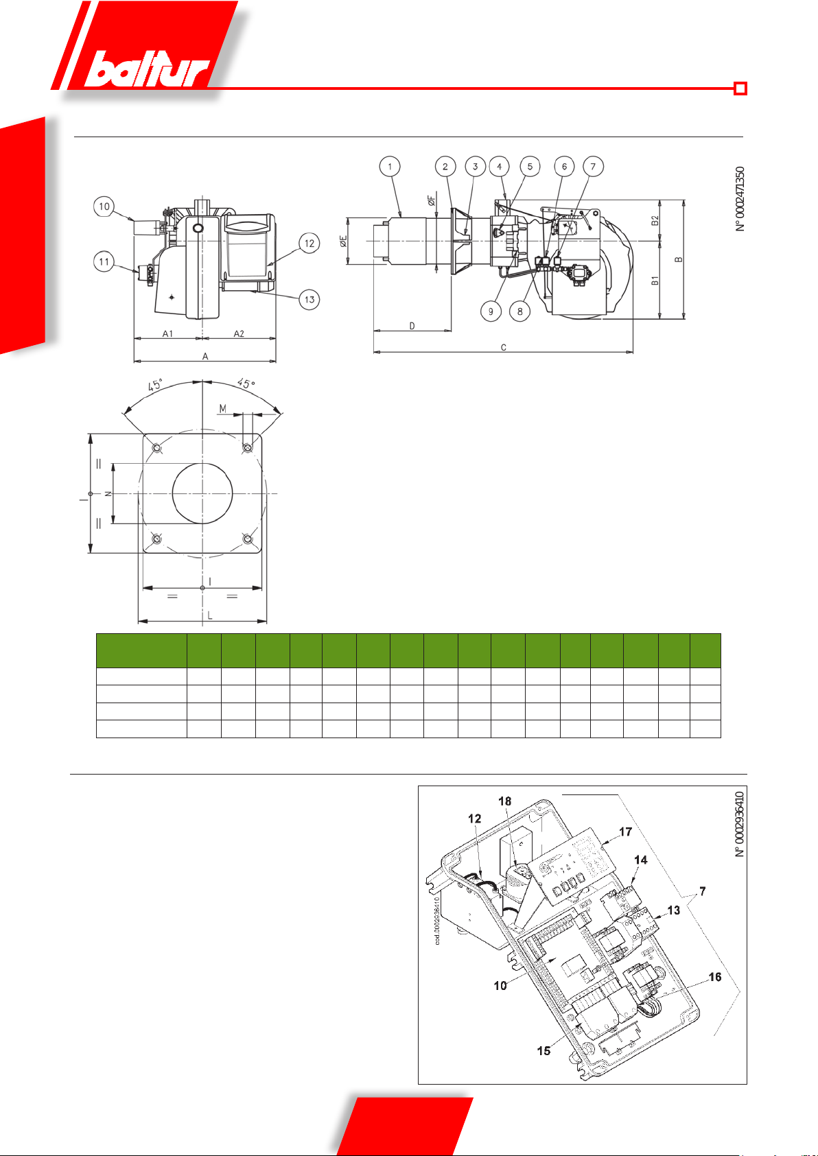
DIMENSIONI DI INGOMBRO
ITALIANO
1) Testa di combustione
2) Guarnizione
3) Flangia fissaggio bruciatore/caldaia
4) Flangia fissaggio rampa gas
5) Dispositivo regolazione testata
6) Elettrovalvola 2° fiamma
7) Elettrovalvola di sicurezza
8) Elettrovalvola 1° fiamma
9) Cerniera
10) Servomotore regolazione aria / gas
11) Pompa
12) Quadro elettrico
13) Motore
A A1 A2 B B1 B2 C D
TBML 80 MC 700 330 370 580 380 200 1230 270 440 180 178 280 250 325 M12 190
TBML 120 MC 700 330 370 580 380 200 1250 285 450 224 219 320 280 370 M12 235
TBML 160 MC 700 330 370 580 380 200 1250 285 450 224 219 320 280 370 M12 235
TBML 200 MC 700 330 370 580 380 200 1270 300 470 250 219 320 300 370 M12 255
D
mín
máxE ØFØ
I L
mín
L
máx
COMPONENTI QUADRO ELETTRICO
10) Apparecchiatura
12) Trasformatore d’accensione
13) Contattore motore
14) Relè termico
15) Spina 7 poli
16) Spina 4 poli
17) Pannello sinottico
M N
6 / 36
0006081544_201408
Page 9
2
4
6
8
0
10
12
14
mbar
0002922743A
100
200 300 400 500 600 700 800 900 1000
kW
15
1100 1200 1300 1400
2
4
6
8
0
10
12
14
mbar
0002922743B
300 400 500 600 700 800 900 1000
kW
15
1100 1200 1300 1400 1500 1600 1700 1800 1900
2000 2100
TBML 80 TBML 120
TBML 160 TBML 200
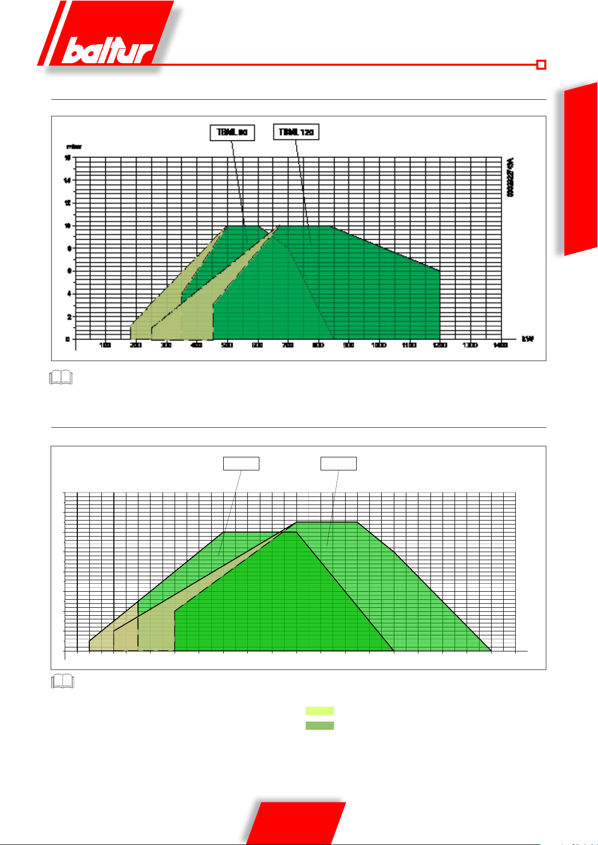
CAMPO DI LAVORO TBML 80 MC - 120 MC
Potenza termica min TBML 80 gpl = 190kW
ITALIANO
CAMPO DI LAVORO TBML 160 MC - 200 MC
Potenza termica max TBML 200 gpl = 1930kW
I campi di lavoro sono ottenuti su c aldai e di prova risp on denti alla
norma EN 267 e sono orient ativi per gli ac c oppiamenti b ruc iatore
caldaia. Per il corretto funzionamento del bruciatore le dim ens i o ni
della camera di combustione devono essere rispondenti alla
normativa vigente; in caso contrario vanno consultati i costruttori.
Potenza termica Metano
Potenza termica Gasolio
7 / 36
0006081544_201408
Page 10
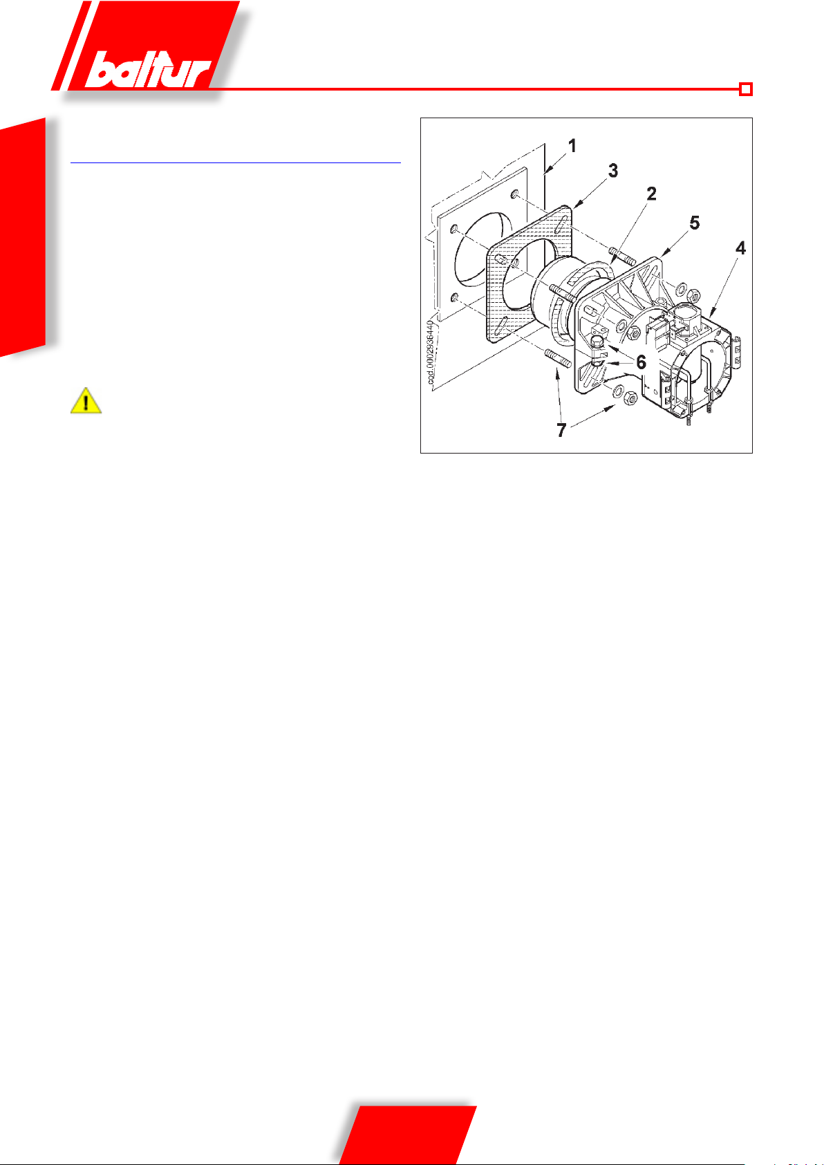
APPLICAZIONE DEL BRUCIATORE
ALLA CALDAIA
MONTAGGIO GRUPPO TESTATA
• Adeguare la posizione della angia di attacco 5 allentando le
viti 6 in modo che la testata di combustione penetri nel focolare
della quantità consigliata dal costruttore del generatore.
• Inserire il tubino rigido nell’alloggiamento ricavato sulla angia
ITALIANO
di attacco e bloccarlo con la vite. Tale tubino andrà tagliato a
lo diffusore (vedi 0002934670).
• Posizionare sul cannotto la guarnizione isolante 3 interponendo
la corda 2 tra angia e guarnizione.
• Fissare il Gruppo Testata 4 alla caldaia 1 tramite i prigionieri, le
rondelle e i relativi dadi in dotazione 7.
Sigillare completamente con materiale idoneo lo spazio tra
il canotto del bruciatore e il foro sul refrattario all’interno del
portellone caldaia.
8 / 36
0006081544_201408
Page 11
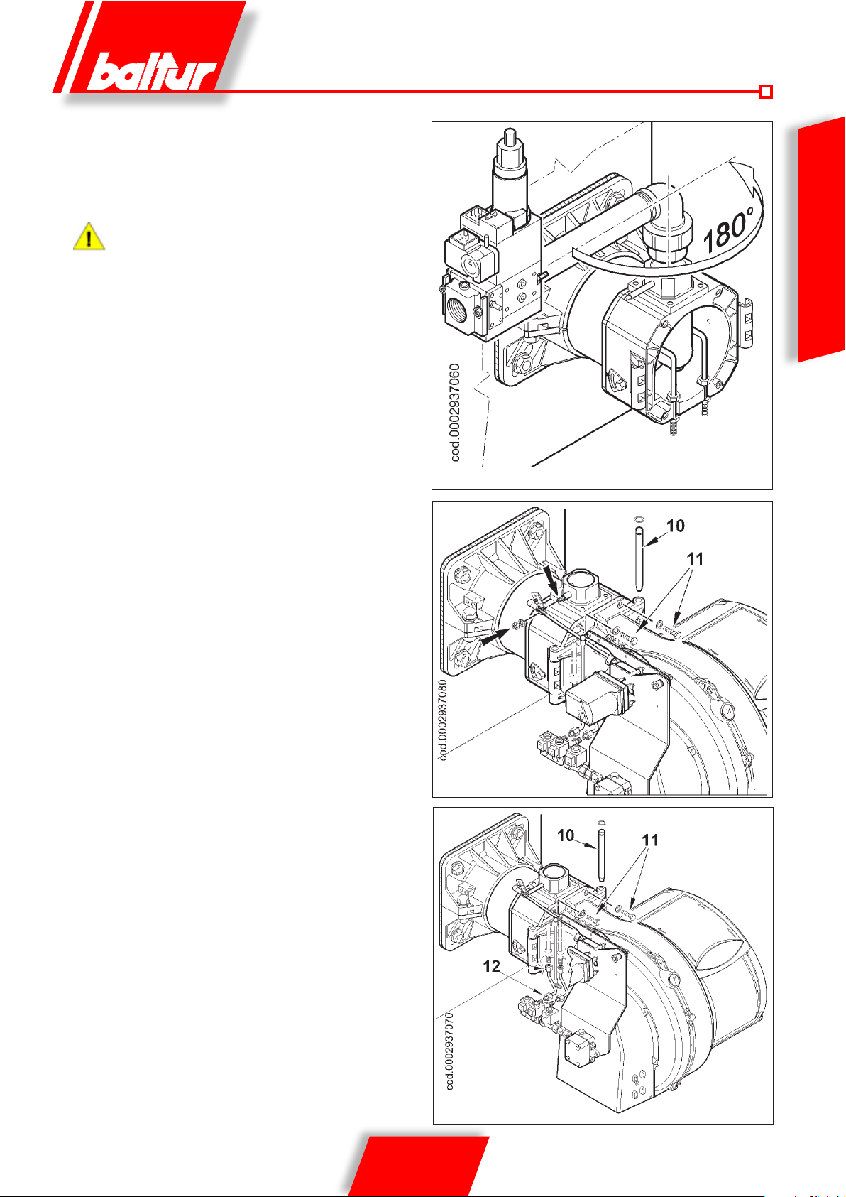
MONTAGGIO RAMPA GAS
Sono possibili diverse soluzioni di montaggio della rampa valvole come evidenziato nel disegno 0002936400.
Scegliere la posizione più razionale in base alla conformazione
del locale caldaia e alla posizione di arrivo della tubazione gas.
Con Valvole di dimensioni notevoli es. DN65 o DN80
prevedere un adeguato supporto per evitare sollecitazioni
eccessive al raccordo di attacco della rampa gas.
MONTAGGIO CORPO VENTILANTE
• Posizionare le semicerniere presenti sulla chiocciola bruciatore
in corrispondenza di quelle presenti sul gruppo testata.
• Inlare il perno cerniera 10 nella posizione ritenuta più idonea.
• Collegare i cavi di accensione ai relativi elettrodi, chiudere la
cerniera bloccando il bruciatore mediante le viti 11 (N.4) .
• Inserire la leva comando farfalla gas sull’albero bloccandola
con il relativo dado.
ITALIANO
COMPLETAMENTO BRUCIATORE
• Rimuovere i tappi di protezione in plastica (gialli) dai raccordi
posti sotto il GruppoTestata e in prossimità delle elettrovalvole.
• Collegare i tubini gasolio 12 in dotazione al bruciatore ai rispettivi
raccordi vericandone la perfetta tenuta idraulica.
9 / 36
0006081544_201408
Page 12
0002911090
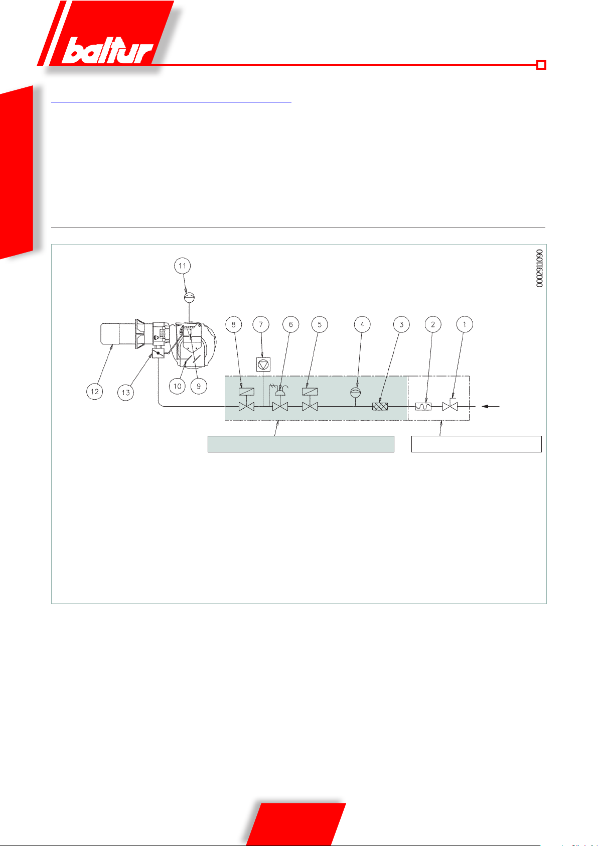
LINEA DI ALIMENTAZIONE GAS
Lo schema di principio della linea di alimentazione gas è riportato
nella figura sotto. La rampa gas è omologata secondo normativa
EN 676 e viene fornita separatamente dal bruciatore.
Occorre installare, a monte della valvola gas, una valvola di
intercettazione manuale e un giunto antivibrante, disposti
secondo quanto indicato nello schema.
ITALIANO
SCHEMA DI PRINCIPIO BRUCIATORE GAS
RAMPA GAS FORNITA DAL COSTRUTTORE A CURA DELL’INSTALLATORE
1) Valvola di intercettazione manuale
2) Giunto antivibrante
3) Filtro gas
4) Pressostato di minima pressione gas
5) Valvola di sicurezza
6) Regolatore di pressione
7) Dispositivo di controllo tenuta valvole (obbligatorio per bruciatore
con portata termica nominale massima superiore a 1200 kW)
8) Valvola di lavoro ad apertura lenta
9) Servomotore regolazione aria / gas
10) Serranda regolazione aria
11) Pressostato aria
12) Testa di combustione
13) Valvola a farfalla regolazione gas
10 / 36
0006081544_201408
Page 13
N° 0002901620
LINEA DI ALIMENTAZIONE GASOLIO
L’esposizione che segu e tiene esclusivamente conto di quanto
necessario per assicurare un buon funzionamento.
L’apparecchio è dot ato di pompa auto-aspirante capace quindi
di aspirare direttamente l’olio dalla cister na anche per il primo
riempimento. Questa af fermazione è valida purché sussistano i
presupposti necess ari, vedi schemi dimensionamento tubazioni.
Per assicurare un buon funzionamento è preferibile che le
tubazioni, di aspirazione e r itorno, siano eseguite con raccordi
saldati evitando le giunzioni a f iletto che spesso consentono
infiltrazioni di ar ia che distur bano il funzi onamento della po mpa e
quindi del bruciatore. Dove sia indispensabile eseguire un raccordo
smontabile, si impieghi il sistema a f lange saldate con inter posta
guarnizione resistente al combustibil e, che assicura un’ottima
tenuta. Per impianti dove la tubazione nece ssiti di un diametro
relativamente modesto, consigliamo l’impieg o del tubo in rame.
Nelle inevitabili giunzioni, consi gliamo l’impiego di raccordi a
“bicono”.
Di seguito sono ripor tati gli schemi di principio per diversi tipi
di impianti in funzione della posizio ne della cisterna rispetto al
bruciatore. La tubazione di aspir azione dovrà essere dispost a in
salita verso il bruci atore, per evitare accumulo di eventuali bolle
di gas. Nel caso in cui vengano installati più bruciatori in un’unica
sala caldaie, è indispensabile c he ogni bruciatore abbia un suo
tubo di aspirazione.
Solo i tubi di ritorno possono confluire in un’unico tubo di
sezione adatta per raggiun gere la cisterna. Evitare in ogni caso
il collegamento diretto del tubo di ritorno sul tubo di aspirazione.
È consigliabile coibentare convenientemente le tubazioni di
aspirazione e di ritor no p er evitar e raffreddamenti funziona lmente
dannosi. I diametri delle tubazioni (da rispettare r igorosamente)
sono riportati nelle seguenti tabelle. La depressione massima che la
pompa può sopportare funzionando regolarmente e silenziosamente
è di 0,47 .bar; se tale valore viene superato, il regolare funzionamento
della pompa non è più garantito.
Pressione massima su aspirazione e ritorno = 1 bar.
POMPA AUSILIARIA
In alcuni casi (eccessiva distanza o dislivello) è necessario effettuare
l’impianto con un circuito di alimentazione ad “anello”, con pompa
ausiliaria, evitando quindi il collegamento diretto della pompa del
bruciatore alla cisterna.
In questo caso la pompa ausiliaria può essere messa in funzione
alla partenza del bruciatore e fermata all’arresto dello stesso.
Il collegamento elettrico della pompa ausiliaria si realizza collegando
la bobina (230 V) che comanda il teleruttore della pompa stessa, ai
morsetti 2 (N) e 17 del circuito stampato.
Si raccomanda di seguire sempre le prescrizioni sotto riportate:
• La pompa ausiliaria deve essere installata il più vicino possibile
al liquido da aspirare.
• La prevalenza deve essere adeguata all’impianto in questione.
• Consigliamo una portata almeno pari alla portata della pompa
del bruciatore.
• Le tubazioni di collegamento devono essere dimensionate in
funzione della portata della pompa ausiliaria.
• Evitare assolutamente il collegamento elettrico della pompa
ausiliaria direttamente al teleruttore del motore del motore del
bruciatore.
ITALIANO
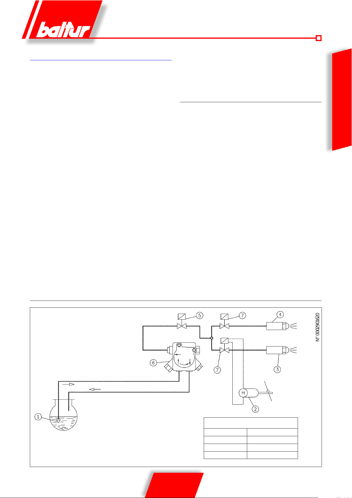
SCHEMA DI PRINCIPIO CIRCUITO IDRAULICO
ASPIRAZIONE
RITORNO
1 - Valvola di fondo
2 - Servomotore regolazione aria
3 - Ugello 2° amma
4 - Ugello 1° amma
5 - Valvola sicurezza normalmente chiusa
6 - Pompa 12 bar
7 - Valvola normalmente chiusa
Perdita di carico circuito idraulico
TBML 80 MC 1 bar
TBML 120 MC 1,5 bar
TBML 160 MC 2 bar
TBML 200 MC 2,5 bar
11 / 36
0006081544_201408
Page 14
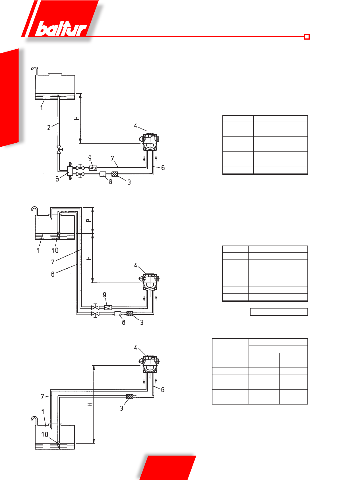
SCHEMI DIMENSIONAMENTO TUBAZIONE TBML 80 MC
IMPIANTO DI ALIMENTAZIONE PER GRAVITA’
ITALIANO
1 Serbatoio
2 Tubazione di alimentazione
3 Filtro a rete
4 Pompa
5 Degasicatore
ASSE POMPA
IMPIANTO A CADUTA CON ALIMENTAZIONE DALLA SOMMITÀ DEL SERBATOIO
1 Serbatoio
3 Filtro a rete
4 Pompa
6 Tubo di aspirazione
7 Tubo di ritorno
6 Tubo di aspirazione
7 Tubo ritorno bruciatore
8 Dispositivo automatico intercettazione
a bruciatore fermo
9 Valvola unidirezionale
H Gesamte L.
Meter Meter
Ø i. 14 mm.
1 30
1,5 35
2 35
2,5 40
3 40
8 Dispositivo automatico intercettazione a
bruciatore fermo
9 Valvola unidirezionale
10 Valvola di fondo
1 Serbatoio
3 Filtro a rete
4 Pompa
6 Tubo di aspirazione
7 Tubo di ritorno
10 Valvola di fondo
ASSE POMPA
IMPIANTO DI ALIMENTAZIONE IN ASPIRAZIONE
ASSE POMPA
N.B. Per eventuali organi mancanti nelle tubazioni attenersi alle norme vigenti.
H Gesamte L.
Meter Meter
Ø i. 14 mm.
1 30
1,5 35
2 35
2,5 40
3 40
Maßzahl T = 3,5 m. (Max.)
L. Complessiva
H
metri
0,5 26 45
1 22 38
1,5 19 31
2 14 25
2,5
metri
Ø i. 14
mm.
11 19
Ø i. 16
mm.
H = Dislivello tra minimo livello in serbatoio e asse pompa.
L = Lunghezza totale della tubazione compreso il tratto verticale.
Per ogni gomito o saracinesca detrarre 0,25 m.
12 / 36
0006081544_201408
Page 15
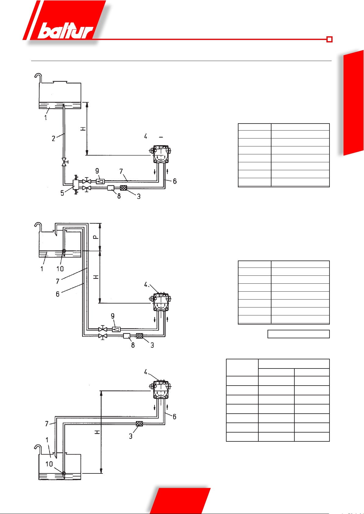
SCHEMI DIMENSIONAMENTO TUBAZIONE TBML 120 MC - 160 MC - 200 MC
IMPIANTO DI ALIMENTAZIONE PER GRAVITA’
1 Serbatoio
2 Tubazione di alimentazione
3 Filtro a rete
4 Pompa
5 Degasicatore
ASSE POMPA
IMPIANTO A CADUTA CON ALIMENTAZIONE DALLA SOMMITÀ DEL SERBATOIO
1 Serbatoio
3 Filtro a rete
4 Pompa
6 Tubo di aspirazione
7 Tubo di ritorno
ASSE POMPA
6 Tubo di aspirazione
7 Tubo ritorno bruciatore
8 Dispositivo automatico intercettazione
a bruciatore fermo
9 Valvola unidirezionale
H Gesamte L.
Meter Meter
Ø i. 16 mm.
1 40
1,5 45
2 45
2,5 50
3 50
8 Dispositivo automatico intercettazione a
bruciatore fermo
9 Valvola unidirezionale
10 Valvola di fondo
H Gesamte L.
Meter Meter
Ø i. 16 mm.
1 40
1,5 45
2 45
2,5 50
3 50
ITALIANO
1 Serbatoio
3 Filtro a rete
4 Pompa
6 Tubo di aspirazione
7 Tubo di ritorno
10 Valvola di fondo
IMPIANTO DI ALIMENTAZIONE IN ASPIRAZIONE
ASSE POMPA
N.B
. Per eventuali organi mancanti nelle tubazioni attenersi alle norme vigenti.
H = Dislivello tra minimo livello in serbatoio e asse pompa.
L = Lunghezza totale della tubazione compreso il tratto verticale.
Per ogni gomito o saracinesca detrarre 0,25 m.
13 / 36
0006081544_201408
Maßzahl T = 3,5 m. (max.)
H
metri
0,5 36 55
1 30 48
1,5 25 41
2 20 32
2,5 15 24
3 10 15
3,5 4 7,5
L. Complessiva metri
Ø i. 14 mm. Ø i. 16 mm.
Page 16
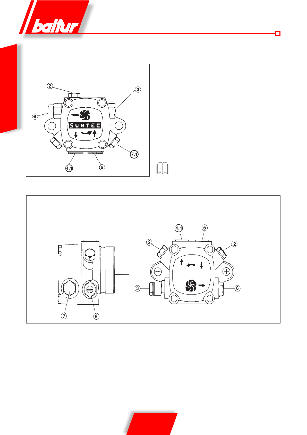
PARTICOLARI POMPA SUNTEC
ITALIANO
AJ4 - AJ6
AN 47 - 57 - 67 - 77 - 97
2 ATTACCO MANOMETRO E SFOGO ARIA (1/8” G)
3 VITE REGOLAZIONE PRESSIONE
8894-1
3.1 ASPORTARE IL DADO PER ACCEDERE ALLA VITE DI
REGOLAZIONE DELLA PRESSIONE (AN..11-14 BAR, AJ..1116 BAR)
4 RITORNO
4.1 RITORNO CON GRANO DI BY-PASS INTERNO
5 ASPIRAZIONE
6 MANDATA
7 ATTACCO VUOTOMETRO (1/8” G)
7.1 ATTACCO VACUOMETRO E GRANO DI BY-PASS INTERNO
La pompa viene pre-regolata ad una pressione di 12 bar.
0002900331
14 / 36
0006081544_201408
Page 17
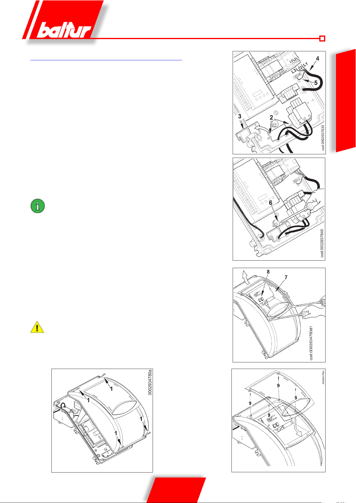
COLLEGAMENTI ELETTRICI
La linea di alimentazione trifase deve essere provvista di interruttore
con fusibili. E’ inoltre richiesto dalle Norme un interruttore sulla linea
di alimentazione del bruciatore, posto all’esterno del locale caldaia in
posizione facilmente raggiungibile. Per i collegamenti elettrici (linea e
termostati) attenersi allo schema elettrico allegato. Per eseguire il collegamento del bruciatore alla linea di alimentazione procedere come
segue:
• Rimuovere il coperchio svitando le 4 viti (1) di gura 1, senza togliere
lo sportellino trasparente In questo modo è possibile accedere al
quadro elettrico del bruciatore.
• Allentare le viti (2) e, dopo aver rimosso la piastrina stringicavi (3),far
passare attraverso il foro le due spine a 7 e a 4 poli (vedi gura 2).
Collegare i cavi di alimentazione (4) al teleruttore, ssare il cavo di
terra (5) e serrare il relativo pressacavo.
• Riposizionare la piastrina stringicavi come da gura 3.Ruotare l’ec-
centrico (6) in modo che la piastrina eserciti una adeguata pressione
sui due cavi, quindi stringere le viti che ssano la piastrina.Collegare
inne le due spine a 7 e a 4 poli.
gli alloggiamenti dei cavi per le spine a 7 e 4 poli sono previsti
rispettivamente per cavo Φ 9,5÷10 mm e Φ 8,5÷9 mm, questo
per assicurare il grado di protezione IP 54 (Norma CEI EN60529)
relativamente al quadro elettrico.
ITALIANO
Figura 2
• Per richiudere il coperchio del quadro elettrico, avvitare le4 viti (1)
esercitando una coppia di serraggio di circa 5 Nm per assicurare la
corretta tenuta. A questo punto, per accedere al pannello comandi
(8), sganciare lo sportellino trasparente (7), esercitando una leggera
pressione con un utensile (esempio cacciavite) nella direzione delle
frecce di gura 4, farlo scorrere per un breve tratto e separarlo dal
coperchio.
• Per una corretta risistemazione dello sportellino trasparente sul
quadro procedere come indicato in gura 5:posizionare i ganci in
corrispondenza delle rispettive sedi (9), far scorrere lo sportellino
nella direzione indicata dalla freccia no ad avvertire un leggero
scatto. A questo punto è garantita un’adeguata tenuta.
l’apertura del quadro elettrico del bruciatore è consentita
esclusivamente a personale professionalmente qualificato.
Figura 3
Figura 4
Figura 1 Figura 5
15 / 36
0006081544_201408
Page 18
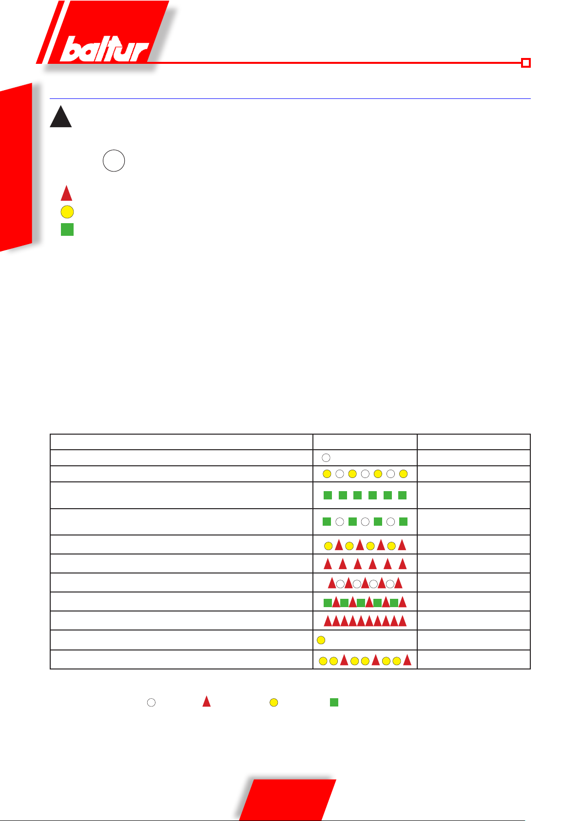
APPARECCHIATURA DI COMANDO E CONTROLLO PER BRUCIATORI A GAS LME 73...
per ulteriori informazioni consultare la Guida rapida dell’apparecchiatura fornita a corredo con il manuale.
!
Info
↵
ITALIANO
ROSSO
GIALLO
VERDE
Entrambi il pulsante reset di blocco (EK) e la spia multicolore (LED) sono collocate nel pannello di controllo.
Abbiamo 2 scelte di diagnostica:
1.Diagnostica visuale: indicazione dello stato operativo oppure diagnostica della causa del blocco
2.Diagnostica: visualizzazione e unità operativa attraverso BCI no a AZL2 …
1
)diagnostica visuale:
in operatività normale, i differenti stati operativi sono indicati sotto forma di codice colore secondo la tabella dei colori qui sotto.
Il pulsante reset di blocco
bruciatore e per attivare/disattivare le funzioni diagnostiche.
La spia multicolore (LED) è l’elemento chiave indicativo per le diagnostiche visuali.
1
) (pulsante info) (EK) è l’elemento operativo chiave per resettare il controllo del
INDICAZIONI DI STATO OPERATIVE
Durante l’accensione, si hanno indicazioni di stato secondo la seguente tabella:
Tabella codici colori per la spia (LED)
Condizione / stato Sequenza colori Colori
Tempo di attesa (TW), altri stati intermedi
Fase di accensione, accensione controllata
Funzionamento corretto, intensità di corrente rilevatore amma superio-
re al minimo ammesso
Funzionamento non corretto, intesità di corrente rilevatore amma
inferiori al minimo ammesso
Diminuzione tensione di alimentazione
Condizione di blocco bruciatore
Segnalazione guasto (vedere legenda colori)
Luce parassita durante l’accensione del bruciatore
Diagnostica interfaccia
Richiesta calore
Nuova scheda programma
Legenda
..... Acceso sso Off Rosso Giallo Verde
. . . . . . . . . . . . . . . .
. . . . . . . .. . . . . . . . . .
Giallo e Rosso alternati
Verde Rosso alternati
Rosso lampeggiante rapido
OFF
Giallo intermittente
Verde
Verde intermittente
Rosso
Rosso intermittente
Giallo
Giallo - giallo - rosso
16 / 36
0006081544_201408
Page 19
PME7... PROGRAM MODULE FOR LME7...WITH PROGRAM SEQUENCES OIL OR GAS BURNERS FOR
LME7...BASIC UNIT REFER TO BASIC DOCUMENTATION P7105
Type reference PME73.810A2 PME73.820A2 PME73.830A2 PME73.840A2
For operation with LME73.000A... x x x x
Gas program forced draft burner x x x x
1-stage / 2-stage or 1-stage modulating x x x x
Pilot burner intermittent / interrupt --- --- x x
Modulating via actuator (pneumatically, mechanical gas-air ratio
control
Actuator control via analog signal / 3-position step signal for actuator
with potentiometer
3-position step signal for actuator without potentiometer --- x --- x
Control sequence programmable time x x x x
POC x x x x
Valve proving x x x x
x x x x
x --- x ---
ITALIANO
Apparecchiatura o
programmatore
Tempo di
sicurezza
Tempo di
preventilazione
Pre-
accensione
Post-
accensione
Tempo tra apertura
valvola 1° amma e
valvola 2° amma
Tempo di corsa
apertura ser-
randa
LME 73... 3 30 2 2 11 30 30
DESCRIZIONE DEL FUNZIONAMENTO
CON COMBUSTIBILE LIQUIDO
PRECISAZIONI PER L ’ ACCENSIONE DEL BRUCIATORE MISTO
si consiglia di effettuare prima l’accensione con combustibile liquido
perchè l’erogazione è, in questo caso, condizionat a dall’ugello
utilizzato, mentre l’erogazione del gas metano p uò esser e variata
a piacere agendo sul relativo regolatore di portata.
E’ sconsigliabile sovradimensionare il bruciatore alla caldaia per
riscaldamento e produzione di acqua calda sanitaria, in quanto il
bruciatore può lavorare anche per lunghi periodi ad una sola amma,
facendo lavorare la caldaia ad una potenzialità inferiore a quella
richiesta; di conseguenza, i prodotti di combustione (fumi) escono
ad una temperatura eccessivamente bassa (circa 180° C per olio
combustibile e 130° C per il gasolio), dando luogo a presenza di
fuliggine allo sbocco del camino. Inoltre quando la caldaia lavora
a potenzialità inferiori a quelle indicate nei dati tecnici, è molto
probabile la formazione di condensa acida e di fuliggine in caldaia
con conseguente rapido intasamento e corrosione della stessa.
Quando il bruciatore a due amme è installato su una caldaia per
produzione di acqua calda ad uso riscaldamento, deve essere
collegato in modo da lavorare a regime normale con entrambe
le amme, arrestandosi completamente, senza passaggio alla
prima amma, quando la temperatura prestabilita viene raggiunta.
Per ottenere questo particolare funzionamento, non si installa il
termostato della seconda amma, e fra i rispettivi morsetti della
spina a quattro poli, si realizza un collegamento diretto (ponte).
In tal modo si utilizza solo la capacità del bruciatore di accendersi
a portata ridotta per realizzare una accensione dolce, condizione
indispensabile per le caldaie con camera di combustione in
pressione (pressurizzata), ma molto utile anche nelle caldaie normali
(camera di combustione in depressione). Il comando (inserzione o
arresto) del bruciatore è subordinato ai soliti termostati di esercizio
o sicurezza.
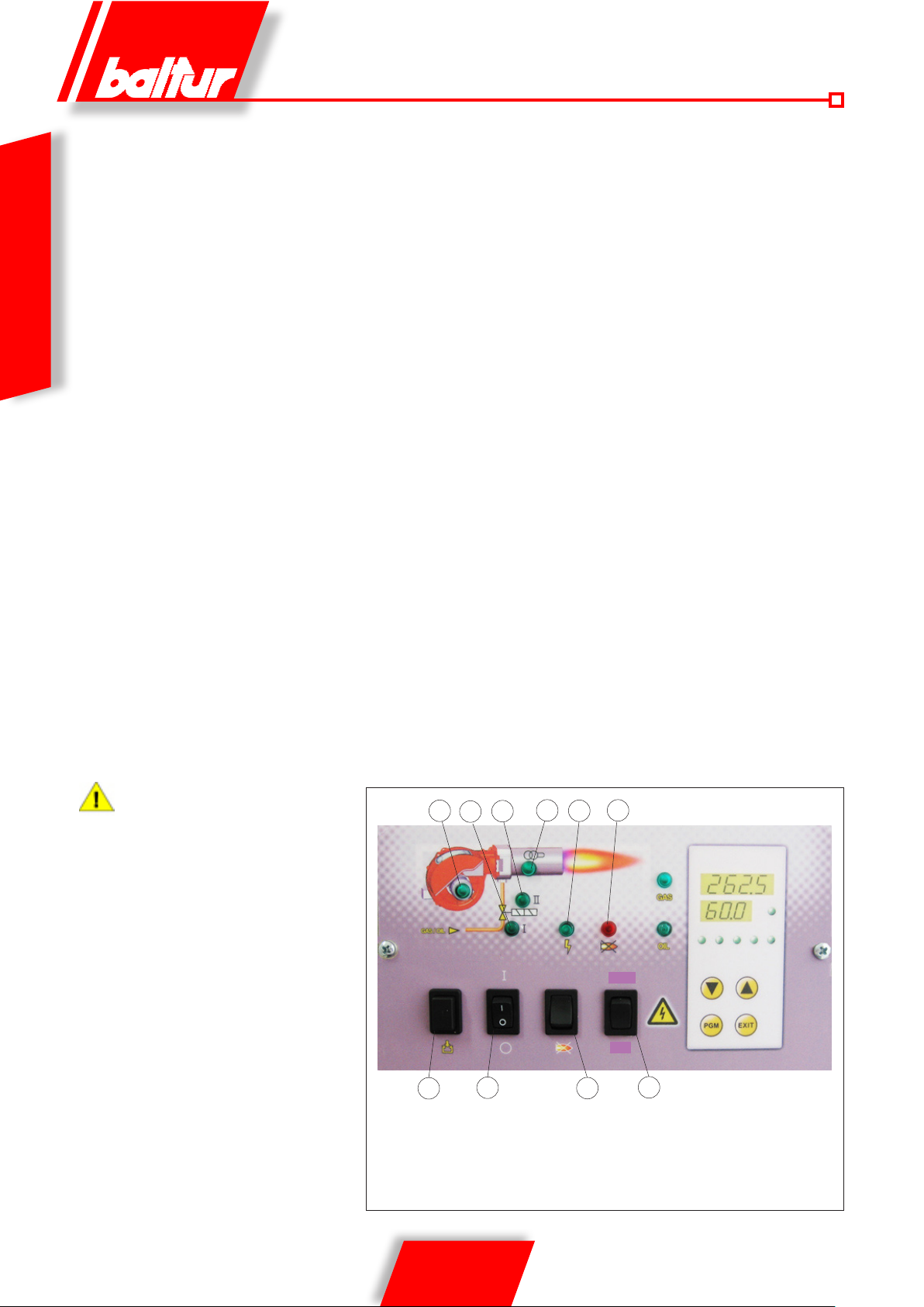
Chiudendo l’interruttore 1, se i termostati sono chiusi, la tensione
raggiunge l’apparecchiatura di comando e controllo (accensione led
2) che inizia il suo funzionamento. Vengono cosi inseriti il motore
del ventilatore (led 3) e il trasformatore di accensione (led 4).
Il motore mette in rotazione la ventola che effettua un lavaggio con
aria della camera di combustione e contemporaneamente la pompa
del combustibile che determinano una circolazione nei condotti
espellendo, attraverso il ritorno, eventuali bolle di gas. Questa
fase di prelavaggio ha termine con l’apertura dell’elettrovalvole di
sicurezza e di 1° amma (led 5) ciò consente al combustibile, alla
pressione di 12 bar, di raggiungere l’ugello della 1° amma e da
questo, uscire in camera di combustione nemente polverizzato.
Appena il combustibile polverizzato esce dall’ugello viene incendiato
dalla scarica presente tra gli elettrodi sin dalla partenza del motore.
Durante l’accensione della prima amma la serranda dell’aria
Tempo di corsa
chiusura serranda
17 / 36
0006081544_201408
Page 20
è mantenuta nella posizione registrata sull’apposita camma del
servomotore regolazione aria / gas. Se compare regolarmente la
amma, superato il tempo di sicurezza previsto dall’apparecchiatura
elettrica, questa inserisce il servomotore regolazione aria / gas che
si porta in posizione di 2° amma. Nella fase di passaggio dalla
prima alla seconda amma il servomotore inserisce l’elettrovalvola
(normalmente chiusa) della 2° amma (led 6). L’apertura della
valvola della 2° amma consente al gasolio, alla pressione di 12 bar,
di raggiungere il 2° ugello; il bruciatore è così funzionante a pieno
regime. Dal momento della comparsa della amma in camera di
ITALIANO
combustione il bruciatore è controllato e comandato dal dispositivo
controllo amma e dai termostati.
L’apparecchiatura di comando prosegue il programma e stacca il
trasformatore d’accensione. Quando la temperatura o pressione in
caldaia raggiunge il valore a cui è tarato il termostato o pressostato,
lo stesso interviene determinando l’arresto del bruciatore.
Successivamente, per l’abbassarsi della temperatura o pressione
al di sotto del valore di richiusura del termostato o pressostato,
il bruciatore viene nuovamente acceso. Se per qualsiasi motivo,
durante il funzionamento viene a mancare la amma, interviene
immediatamente (tempo un secondo) il dispositivo controllo
fiamma che interrompendo l’alimentazione del relè omonimo,
determina automaticamente la disinserzione delle elettrovalvole che
intercettano il usso degli ugelli. Si ripete così la fase di accensione
e, se la fiamma si riaccende normalmente, il funzionamento
del bruciatore riprende regolarmente, in caso contrario (amma
irregolare o completamente assente) l’apparecchio si porta
automaticamente in blocco (led 7). Se il programma viene interrotto
(mancanza di tensione, intervento manuale, intervento di termostato,
ecc.) durante la fase di prelavaggio il programmatore ritornerebbe
nella sua posizione iniziale e ripeterebbe automaticamente tutta la
fase di accensione del bruciatore.
la scelta degli ugelli, in funzione della portata
totale (2 ugelli in funzione), deve essere
effettuata tenendo conto dei valori di portata
corrispondenti alla pressione di lavoro di
12 bar del gasolio. È possibile variare,
entro ampi limiti il rapporto tra la prima e la
seconda fiamma sostituendo gli ugelli.
4
5
6
9
1 Interruttore generale ACCESO-SPENTO
2 Spia presenza tensione
3 Spia funzionamento ventilatore
4 Spia inserzione trasformatore
5 Spia funzionamento 2° stadio
1
23
8
7
display TBML 80 PN
GAS
OIL
10
6 Spia funzionamento 1° stadio
7 Spia blocco apparecciatura
8 Pulsante sblocco apparecchiatura
9 Pulsante caricamento combustibile
10 Selettore combustibile
18 / 36
0006081544_201408
Page 21

PRIMO RIEMPIMENTO TUBAZIONE
ACCENSIONE E REGOLAZIONE
Dopo aver controllato che i tappi di protezione in plastica posti dentro
gli attacchi della pompa siano stati asportati, si procede come segue:
• Portare nella posizione “O” l’interruttore posto sul bruciatore
in modo da evitare l’inserzione automatica del bruciatore.
• Assicurarsi, se il bruciatore è trifase, che il motore giri nel senso
antiorario, guardando il bruciatore dal lato pompa. Il senso di
rotazione può essere rilevato anche guardando il senso di rotazione della ventola attraverso la spia posta sulla parte posteriore
della chiocciola. Per mettere in funzione il motore, chiudere
manualmente il teleruttore (premendo sulla parte mobile) per
qualche istante, ed osservare il senso di rotazione della ventola.
Se fosse necessario cambiare il senso di rotazione, invertire le
due fasi ai morsetti del contattore motore K1.
Attendere, per stabilire con sicurezza il senso di rotazione,
che la ventola giri molto lentamente poiché è possibile una
interpretazione errata del senso di rotazione.
• Staccare se già sono stati collegati, i tubi essibili dalla tubazione
di aspirazione e da quella di ritorno.
• Immergere l’estremità del tubo essibile di aspirazione in un
recipiente contenente olio lubricante o olio combustibile (non
impiegare prodotti con bassa viscosità come gasolio, petrolio,
kerosene, ecc.).
• Premere ora sul pulsante (9) del quadro di comando per mettere
in funzione il motore stesso e quindi la pompa. Attendere che
la pompa abbia aspirato una quantità di lubricante pari a 1 o
2 bicchieri, quindi fermare. Questa operazione ha lo scopo di
evitare il funzionamento della pompa a secco e di aumentare
il potere aspirante.
Le pompe che lavorano a 2800 giri non devono assolutamente
lavorare a secco, perché si bloccherebbero (grippaggio) in
brevissimo tempo.
• Collegare ora il essibile al tubo di aspirazione ed aprire tutte le
eventuali saracinesche poste su questo tubo nonché ogni altro
eventuale organo di intercettazione del combustibile.
• Premere ora nuovamente sul pulsante “9” per mettere in funzione la pompa che aspirerà il combustibile dalla cisterna.Quando
si vedrà uscire il combustibile dal tubo di ritorno (non ancora
collegato), fermare.
Se la tubazione è lunga, può essere necessario sfogare
l’aria dall’apposito tappo, se la pompa non ne è provvista,
asportare il tappo dell’attacco manometro.
• Collegare il tubo essibile di ritorno alla tubazione ed aprire le
saracinesche poste su questo tubo. Il bruciatore è così pronto
per essere acceso.
Prima dell’accensione è necessario assicurarsi che:
• Sia selezionato il tipo di combustibile corretto.
• I collegamenti con la linea di alimentazione, con i termostati
o pressostati, siano eseguiti esattamente secondo lo schema
elettrico dell’apparecchiatura.
• Ci sia combustibile in cisterna e acqua nella caldaia.
• Tutte le saracinesche poste sulla tubazione di aspirazione e
ritorno dell’olio combustibile siano aperte e così pure ogni altro
organo di intercettazione del combustibile.
• Lo scarico dei prodotti di combustione possa avvenire liberamente (serrande della caldaia e del camino aperte).
• Accertarsi che la testa di combustione penetri nel focolare
nella misura richiesta dal costruttore della caldaia. Vericare
che il dispositivo di chiusura aria sulla testa di combustione sia
nella posizione adatta a garantire una corretta combustione, il
passaggio dell’aria tra disco e testa deve essere sensibilmente
ridotto nel caso di erogazione combustibile ridotta. Con un’erogazione di combustibile elevata anche il passaggio aria dovrà
aumentare di conseguenza, vedere capitolo “REGOLAZIONE
DELLA TESTA DI COMBUSTIONE”..
• Gli ugelli applicati sul bruciatore siano adatti alla potenzialità della caldaia e, se necessario, sostituirli con altri.
In nessun caso la quantità di combustibile erogata deve essere
superiore a quella massima richiesta dalla caldaia e a quella
massima ammessa per il bruciatore.
Per l’accensione si procede come segue:
I bruciatori sono provvisti di interruttore per passare
manualmente dal 1° al 2° stadio.
• Evitare il funzionamento della seconda amma: posizionare
l’interuttore 1° e 2° stadio situato sul circuito stampato in posizione 1° stadio.
• Regolare l’aria della quantità che si presume necessaria per
l’accensione al 1° stadio attraverso la camma specica del
servomotore regolazione aria.
• Regolare in una posizione intermedia il dispositivo di regolazione
dell’aria sulla testa di combustione vedi “REGOLAZIONE ARIA
SULLA TESTA DI COMBUSTIONE”.
• Inserire l’interruttore generale e quello del quadro di comando.
• Si inserisce il programmatore che incomincia a svolgere il
programma prestabilito, inserendo i dispositivi del bruciatore.
L’apparecchio si accende come descritto nel capitolo “DESCRIZIONE DEL FUNZIONAMENTO”.
• Quando il bruciatore è in funzione al 1° stadio, si provvede a
regolare l’aria nella quantità necessaria per assicurare una
buona combustione, vedi “REGOLAZIONE ARIA SULLA TESTA DI COMBUSTIONE” e 000293 per regolazione camma
1° stadio gsolio.
• Dopo aver regolato l’aria per il 1° stadio si ferma il bruciatore,
togliendo corrente dall’interruttore generale, si chiude il circuito
elettrico che comanda l’inserzione del secondo stadio posizionando l’interuttore 1° e 2° stadio situato sul circuito stampato
in posizione 2° stadio
ITALIANO
19 / 36
0006081544_201408
Page 22
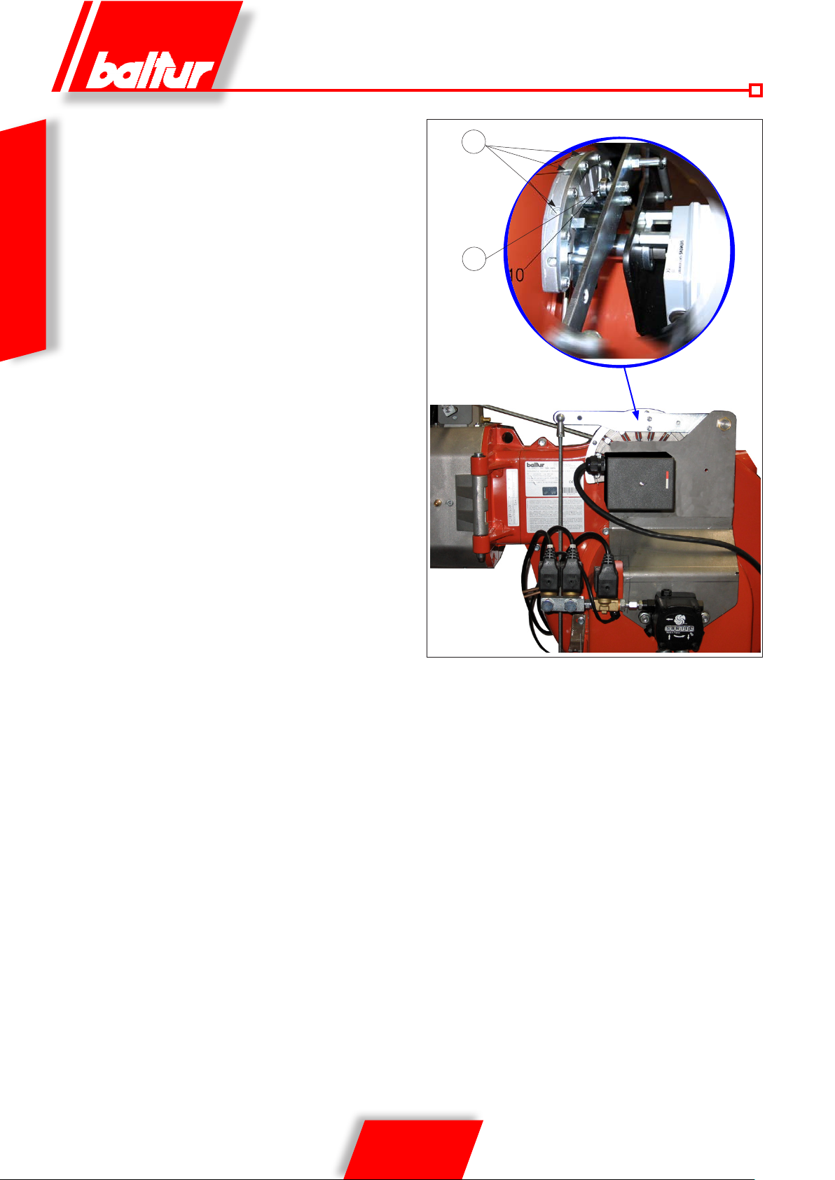
• Regolare l’aria della quantità che si presume necessaria per la portata massima (2° stadio) agendo sulla vite/i in corrispondenza del cuscinetto (13)
- rotazione oraria la portata d’aria aumenta,
- rotazione antioraria la portata d’aria diminuisce..
• Si inserisce ora nuovamente l’apparecchio che si accende e
passa automaticamente, secondo il programma stabilito dal
programmatore, al 2° stadio.
• Con l’apparecchio così in funzione al 2° stadio, si provvede a
ITALIANO
regolare, l’aria nella quantità necessaria per assicurare una
buona combustione. Il controllo della combustione dovrebbe
essere effettuato con gli appositi strumenti. Se non si dispone degli strumenti adatti ci si basa sul colore della amma.
Consigliamo di regolare la combustione in modo da ottenere una fiamma morbida, di colore arancio chiaro
evitando fiamma rossa con presenza di fumo, come
pure fiamma bianca con esagerato eccesso di aria.
Il regolatore dell’aria deve essere in posizione tale da consentire
una percentuale di anidride carbonica (CO2) nei fumi, variabile
da un minimo del 10% ad un massimo del 13% con un numero
di fumo non superiore al n° 2 (scala Bacharach)
12
acc_reg001.psd
13
TBML 80MC 003.psd
20 / 36
0006081544_201408
Page 23
DESCRIZIONE DEL FUNZIONAMENTO
CON COMBUSTIBILE GASSOSO
DESCRIZIONE DEL FUNZIONAMENTO
DELLA MODULAZIONE
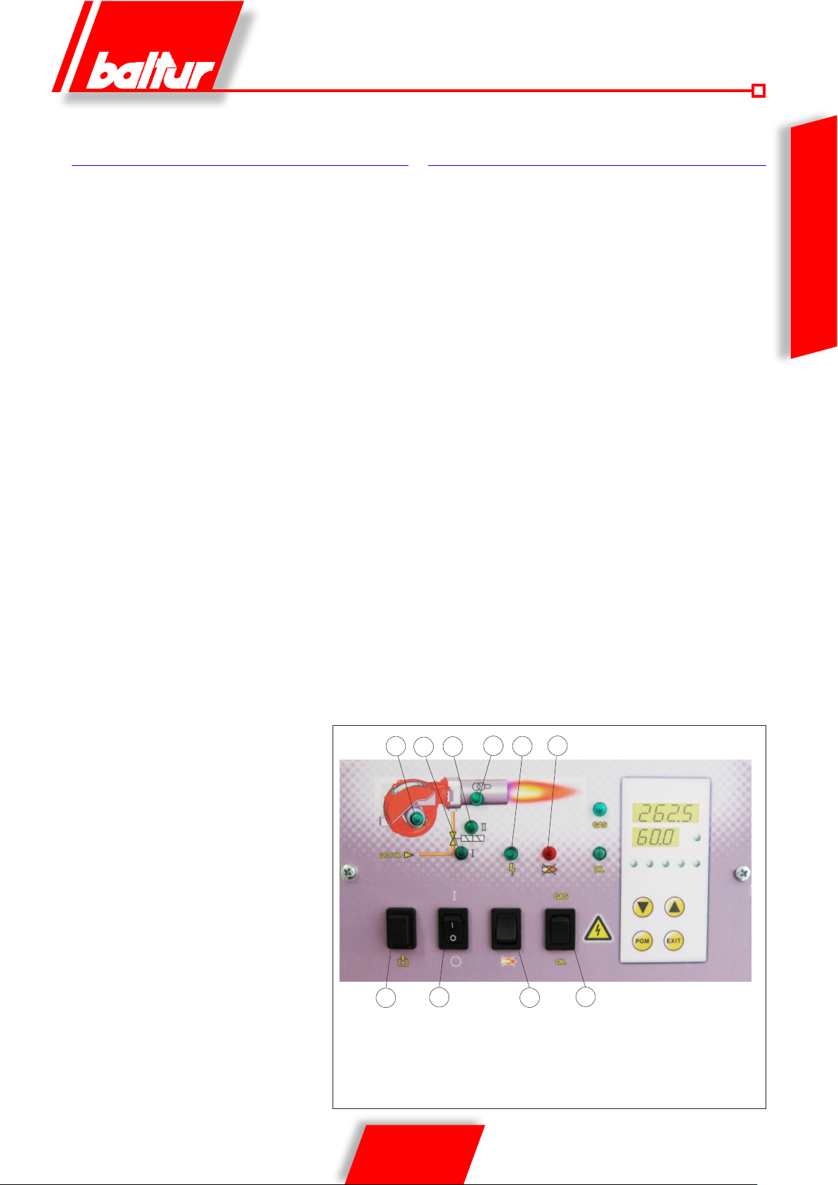
Chiudendo l’interruttore “1”, se i termostati sono chiusi, la tensione
raggiunge l’apparecchiatura di comando e controllo (accensione
led 2) che inizia il suo funzionamento. Viene così inserito il motore
del ventilatore (led 3) per effettuare la preventilazione della camera di combustione, contemporaneamente il servomotore di comando della serranda dell’aria si porta nella posizione di apertura corrispondente alla massima potenza regolata.
Al termine della fase di preventilazione la serranda dell’aria
viene riportata nella posizione di amma d’accensione.
Se il pressostato di controllo della pressione dell’aria di ventilazione rileva pressione sufciente, si inserisce il trasformatore d’accensione (led 4) e, dopo due secondi, si aprono le valvole del gas
principale e di sicurezza (led 5).
Precisiamo che:
• La valvola principale è di tipo monostadio ad apertura lenta.
• La valvola di sicurezza è in versione ON/OFF.
• La serranda dell’aria è azionata da un apposito servomotore
elettrico, tenere presente che all’arresto del bruciatore per intervento del termostato, la serranda viene riportata dal servomotore
nella posizione di chiusura.
La presenza della amma, rilevata dal dispositivo di controllo della
stessa, consente il proseguimento e il completamento della fase di
accensione con la disinserzione del trasformatore di accensione.
Successivamente il servomotore apre progressivamente la serran-
da dell’aria e contempiraneamente la valvola a farfalla del gas no
al valore massimo regolato.
Nel caso di assenza amma, l’apparecchiatura si arresta in “blocco di sicurezza” (led 7) entro tre secondi dall’apertura della valvola
principale. In caso di blocco di sicurezza le valvole vengono immediatamente richiuse. Per sbloccare l’apparecchiatura dalla posizione di sicurezza premere il pulsante “8” sul pannellino sinottico.
Quando il bruciatore è acceso alla portata minima, se la sonda di
modulazione lo consente (regolata ad un valore di temperatura o
pressione superiore a quella esistente in caldaia) il servomotore di
regolazione aria / gas inizia a girare;
- rotazione oraria la portata d’aria aumenta,
- rotazione antioraria la portata d’aria diminuisce.
determinando un aumento graduale dell’erogazione di aria di combustione e, di conseguenza del gas, no a raggiungere l’erogazione massima cui il bruciatore è stato regolato. Il bruciatore resta
nella posizione di massima erogazione no a quando la temperatura o pressione raggiunge un valore sufciente a determinare l’in-
tervento della sonda di modulazione che fa ruotare il servomotore
di regolazione aria in senso inverso a quello precedente.
La rotazione all’indietro e quindi la riduzione dell’erogazione aria
e gas, avviene a brevi intervalli di tempo. Con questa manovra
il sistema di modulazione cerca di equilibrare la quantità di calore fornito alla caldaia con quello che la stessa cede all’utilizzo.
La sonda di modulazione applicata alla caldaia rileva le variazioni
di richiesta ed automaticamente provvede a adeguare l’erogazione
di combustibile e di aria comburente inserendo il servomotore di regolazione aria / gas con rotazione in aumento oppure in diminuzione. Se anche con erogazione al minimo si raggiunge il valore limite
(temperatura o pressione) cui è regolato il dispositivo di arresto
completo (termostato o pressostato) il bruciatore viene arrestato
dall’intervento dello stesso.
Riabbassandosi la temperatura o pressione al di sotto del valore di
intervento del dispositivo di arresto il bruciatore viene nuovamente
inserito secondo il programma descritto nel paragrafo precedente.
ITALIANO
4
6
9
0006081544_201408
1
21 / 36
5
7
23
Display TBML 80 PN
GAS
ÖL
8
10
Page 24
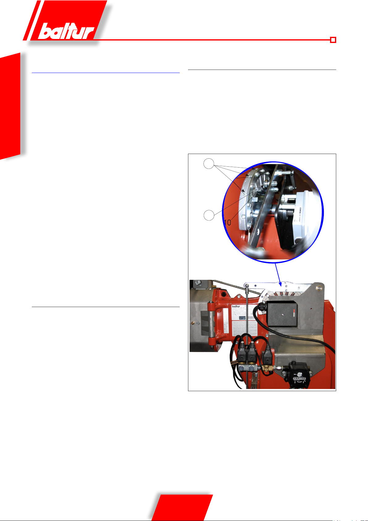
ACCENSIONE E REGOLAZIONE
A GAS METANO
Regolazione della potenza di prima accensione
• posizionare la camma regolazione portata gas di prima amma
sul servomotore elet trico ad un angolo di apertura indicativamente tra i 15° - 20° (000293). Se esiste, aprire completamente
il regolatore di portata della valvola di sicurezza.
• Inserire ora l’interruttore (1 ), l’ apparecchiatura di comando riceve
ITALIANO
così tensione ed il programmatore deter mina l’inserzione del
bruciatore come de scritto nel capitolo “ DESCRIZIONE DEL
FUNZIONAMENTO”. Durante la fase di preventilazione accertarsi che il pressostato di controllo della pressione aria effettui
lo scambio (da posizione di chiuso senz a r il evamento di pressione, deve passare nella posizione di chiuso con rilevamento di
pressione dell’aria). Se il pressostato aria non rileva la pressione
sufciente non viene inserito il trasformatore di accensione (4)
e nemmeno le valvole del gas (5), pertanto l’apparecchiatura
si arresta in “blocco” (7).
• Alla prima accensione possono vericarsi “blocchi” successivi
dovuti a:
- Lo sfogo dell’aria dalla tubazione del gas non è stato eseguito
correttamente e quindi la quantità di gas è insufciente per
consentire una amma stabile.
- Il “blocco” con presenza di amma può essere causato da
instabilità della stessa per un rapporto aria/gas non corretto.
- Correggere la portata d’aria erogata in primo stadio, agendo sulla vite/i (12) in corrispondenza del cuscinetto (13).
- rotazione oraria la portata d’aria aumenta,
- rotazione antioraria la portata d’aria diminuisce.
REGOLAZIONE DELLA POTENZA
IN SECONDO STADIO.
REGOLAZIONE DELLA POTENZA
IN PRIMO STADIO.
T erminata la regolazione del bruciatore in secondo stadio, riportare
il bruciatore in primo stadio. Posizionare l’interruttore sul circuito
stampato in 1° stadio senza variare la regolazione della valvola gas
già effettuata al punto 5a.
- Regolare la portata di gas di 1° stadio al valore desiderato
agendo, sul servomotore elettrico.
- Correggere se necessario l’erogazione di aria comburente
operando sulla vite/i (12) come descritto precedentemente.
- Vericare con gli appositi strumenti i parametri di combustione
in primo stadio (CO2 max= 10%, O2 min=3%, CO max=0,1%).
12
acc_reg001.psd
13
TBML 80MC 003.psd
• Dopo aver completato la regolazione per la prima accensione, spegnere il bruciatore e chiudere il circuito
elettrico che comanda l’inserzione del secondo stadio.
Posizionare l’interruttore sul c ircuito stampato in 2° stadio.
Vericare che la camma di regolazione portata gas di
secondo stadio del servomotore elettrico sia posizionata
a 130°.
- Inserire nuovamente il bruciatore chiudendo l’interruttore
generale (1 ) sul pannello sinottico. Il bruciatore si accende e
automaticamente si porta in secondo stadio. Con l’ausilio degli
appositi strumenti, provvedere alla regolazione dell’erogazione di aria e gas secondo la procedura di seguito descritta:
- Regolare la portata di gas agendo sul regolatore di pressione
della valvola, no ad ottenere valori corretti di combustione,
senza modicare la precedente regolazione aria fatta per il
gasolio. Consultare le istruzioni relative al modello di valvola
gas a singolo stadio installata. Evitar e di mantenere in funzione il bruciatore se la portata termica bruciata è superiore
a quella massima ammessa per la c aldaia, onde evitare
possibili danni alla stessa.
- Vericare con gli appositi strumenti i parametri di combustione
(C02 max= 10%, O2 min=3%, CO max=0,1%)
• Il pressostato aria ha lo sc opo di impedire l’apertura delle
valvole gas se la pressione dell’aria non è quella prevista.
Il pressostato deve quindi essere reg olato per intervenire
chiudendo il contatto quan do la pressione dell’aria nel bru-
ciatore raggiunge il valore sufciente. Qualora il pressostato
aria non rilevi una pression e superiore a quella di taratura,
l’apparecchiatura esegue il suo cic lo ma non si inserisce il
trasformatore d’accensione e non si aprono le valvole del
gas e di conseguenza il br uciatore si arresta in “blocco”.
Per accert are il corretto funzionamento del pres sostato aria
occorre, c on bruciatore acceso in 1° stadio, aumentarne il
22 / 36
0006081544_201408
Page 25

valore di regolazione no a vericarne l’intervento a cui deve
conseguire l’immediato arr esto in “blocco” del bruciatore.
Sbloccare il br uciatore, premendo l’apposito pulsante (8) e
riportare la regolazione del pressostato ad un valore sufciente
per rilevare la pressione di ar ia esistente durante la fase di
preventilazione relativa al 1° stadio.
• Il pressostato di contro llo della pre ssion e del gas (minima) ha
lo scopo di impedire il funzionamento del bruciatore quando la
pressione del gas non risu lta quella pr evista. Il pres sostato di
minima deve utilizzare il contat to che si trova chiuso quando
il pressostato rileva una pressione sup eriore a quella a cui
è regolato. La regolazion e del pressostato di minima deve
quindi avvenire all’atto della messa in funzione de l bruciatore
in funzione della pressione c he si riscontra di volta in volta.
Precisiamo che l’intervento (apertur a di circuito) di qualsiasi
pressostato quando il bruciatore è in funzione (amma accesa)
determina immediatamente l’arresto del bruc iatore. A ll a prima
accensione del bruciatore è indispensabile vericare il corretto
funzionamento dello stesso.
Ultimate le regolazioni accertarsi visivamente che la lamina su
cui agisce il cuscinetto abbia un profilo progressivo. Ver ificare
inoltre con gli appositi strumenti che durante i passaggi da
1° a 2° stadio i parametri di combustione non si discostino
eccessivamente dai valori ottimali.
FOTOCELLULA UV
Una leggera untuosità compromette fortemente il passaggio dei
raggi ultravioletti attraverso il bulbo della fotocellula UV impedendo
che, l’elemento sensibile interno, riceva la quantità di radiazione
necessaria per un corretto funzionamento. Nel caso di imbrattamento
del bulbo con gasolio, olio combustibile ecc., è indispensabile pulire
adeguatamente.
Il semplice contatto con le dita può lasciare una leggera
untuosità, sufficiente a compromettere il funzionamento della
fotocellula UV.
CONTROLLI
• Acceso il bruciatore occorre controllare i dispositivi di sicurezza
(rilevatore amma, blocco, termostati).
• Il dispositivo di controllo amma, deve essere in grado di in-
tervenire durante il funzionamento, nel caso che la amma si
spenga (questo controllo deve essere effettuato dopo almeno
1 minuto dall’avvenuta accensione).
• Il bruciatore deve essere in grado di portarsi in blocco e
restarci quando, in fase di accensione e nel tempo prestabilito dall’apparecchiatura di comando, non compare
regolarmente la fiamma. Il blocco comporta l’arresto immediato del motore e quindi del bruciatore, e l’accensione
della corrispondente segnalazione luminosa di blocco.
Per controllare l’efcienza del rilevatore amma e del blocco,
operare come segue:
- Mettere in funzione il bruciatore.
- Dopo almeno un minuto dall’avvenuta accensione estrarre
il rilevatore amma slandolo dalla sua sede, oscurarlo
simulando così la mancanza di amma. (chiudere con uno
straccio l’apertura dedicata al rilevatore amma. La amma
del bruciatore deve così spegnersi. L’apparecchiatura nel
tempo determinato dal programma, si porta in blocco. Sbloccare l’apparecchiatura solo con intervento manuale pigiando
sull’apposito pulsante.
• 3) Per controllare l’efcienza dei termostati, si fa funzionare
il bruciatore no a quando l’acqua in caldaia raggiunge la
temperatura di almeno 50° C, e quindi, si agisce sulla manopola di comando del termostato nel senso di
abbassare la temperatura fino ad avvertire lo scatto di
apertura e contemporaneamente l’arresto del bruciatore.
Lo scatto del termostato deve avvenire con uno scarto massimo
di 5 ÷ 10° C rispetto al termometro di controllo (termometro di
caldaia) in caso contrario modicare la taratura della scala del
termostato facendola corrispondere a quella del termometro.
ITALIANO
La cellula UV non rileva la luce del giorno o di una comune lampada.
L’eventuale verifica di sensibilità può essere fatta con la fiamma
(accendino, candela) oppure con la scarica elettrica che si manifesta
tra gli elettrodi di un comune trasformatore d’accensione.
Per assicurare un buon funzionamento il valore della corrente di
cellula UV deve essere sufficientemente stabile e non scendere al
di sotto del valore minimo richiesto dall’apparecchiatura specifica,
detto valore è riportato nello schema elettrico. Può essere necessario
ricercare sperimentalmente la miglior posizione facendo scorrere
(spostamento assiale o di rotazione) il corpo che contiene la
fotocellula rispetto alla fascetta di fissaggio. La verifica si effettua
inserendo un micro-amperometro, con scala adeguata, in serie ad
uno dei due cavi di collegamento della fotocellula UV, ovviamente
occorre rispettare la polarità + e -.
l’apparecchiatura LME 73... necessita di una corrente di cellula
compresa tra 200 e 500 microA.
23 / 36
0006081544_201408
Page 26
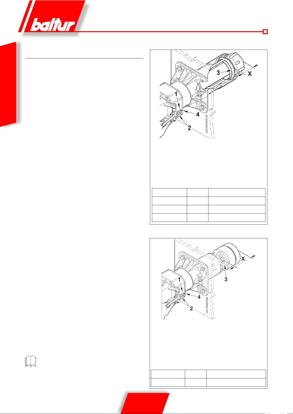
REGOLAZIONE DELL’ ARIA SULLA
TESTA DI COMBUSTIONE
La testa di combustione è dotata di dispositivo di regolazione, in
modo da aprire o chiudere il passaggio dell’aria tra il disco e la
testa. Si riesce così ad ottenere, chiudendo il passaggio , un’elevata
pressione a monte del disco anche con le basse portate. L’elevata
velocità e turbolenza dell’aria consente una migliore penetrazione
della stessa nel combustibile e quindi, un’ottima miscela e stabilità
ITALIANO
di fiamma. Può essere indispensabile avere un’elevata pressione
d’aria a monte del disco, per evitare pulsazioni di fiamma, questa
condizione è praticamente indispensabile quando il bruciatore lavora
su focolare pressurizzato e/o ad alto carico termico.
Da quanto sopra esposto risulta evidente che il dispositivo che
chiude l’aria sulla testa di combustione deve essere portato in
una posizione tale da ottenere sempre dietro al disco un valore
decisamente elevato della pressione dell’aria. Si consiglia di
regolare in modo da realizzare una chiusura dell’aria sulla testa,
tale da richiedere una sensibile apertura della serranda aria che
regola il flusso all’aspirazione del ventilatore bruciatore, ovviamente
questa condizione si deve verificare quando il bruciatore lavora
alla massima erogazione desiderata. In pratica si deve iniziare
la regolazione con il dispositivo che chiude l’aria sulla testa di
combustione in una posizione intermedia, accendendo il bruciatore
per una regolazione orientativa come esposto precedentemente.
Quando si è raggiunta l’erogazione massima desiderata si
provvede a correggere la posizione del dispositivo che chiude l’aria
sulla testa di combustione, spostandolo in avanti o indietro, in modo
da avere un flusso d’aria adeguato all’erogazione, con serranda
dell’aria in aspirazione sensibilmente aperta.
SCHEMA REGOLAZIONE TESTA TBML 80 MC ÷ 160MC
X= Distanza testa-disco; regolare la distanza X seguendo le
indicazioni sottostanti:
• allentare la vite 1
• agire sulla vite 2 per posizionare l’anello regolazione aria
3 riferendosi all’indice 4.
• regolare la distanza X tra il valore minimo e massimo
secondo quanto indicato in tabella.
X Valore indicato dall’indice 4
TBML 80 MC 87 ÷ 95 1 ÷ 1,5
TBML 120 MC 119 ÷ 155 1 ÷ 5
TBML 160 MC 119 ÷ 155 1 ÷ 5
Le regolazioni sopra esposte sono indicative; posizionare
la testa di combustione in funzione delle caratteristiche del
focolare.
SCHEMA REGOLAZIONE TESTA TBML 200 MC
X= Distanza testa-disco; regolare la distanza X seguendo le
indicazioni sottostanti:
• allentare la vite 1
• agire sulla vite 2 per posizionare la testa di combustione 3
riferendosi all’indice 4.
• regolare la distanza X tra il valore minimo e massimo secondo
quanto indicato in tabella.
X Valore indicato dall’indice 4
TBML 200 MC 110 ÷ 150 4 ÷ 1
24 / 36
0006081544_201408
Page 27
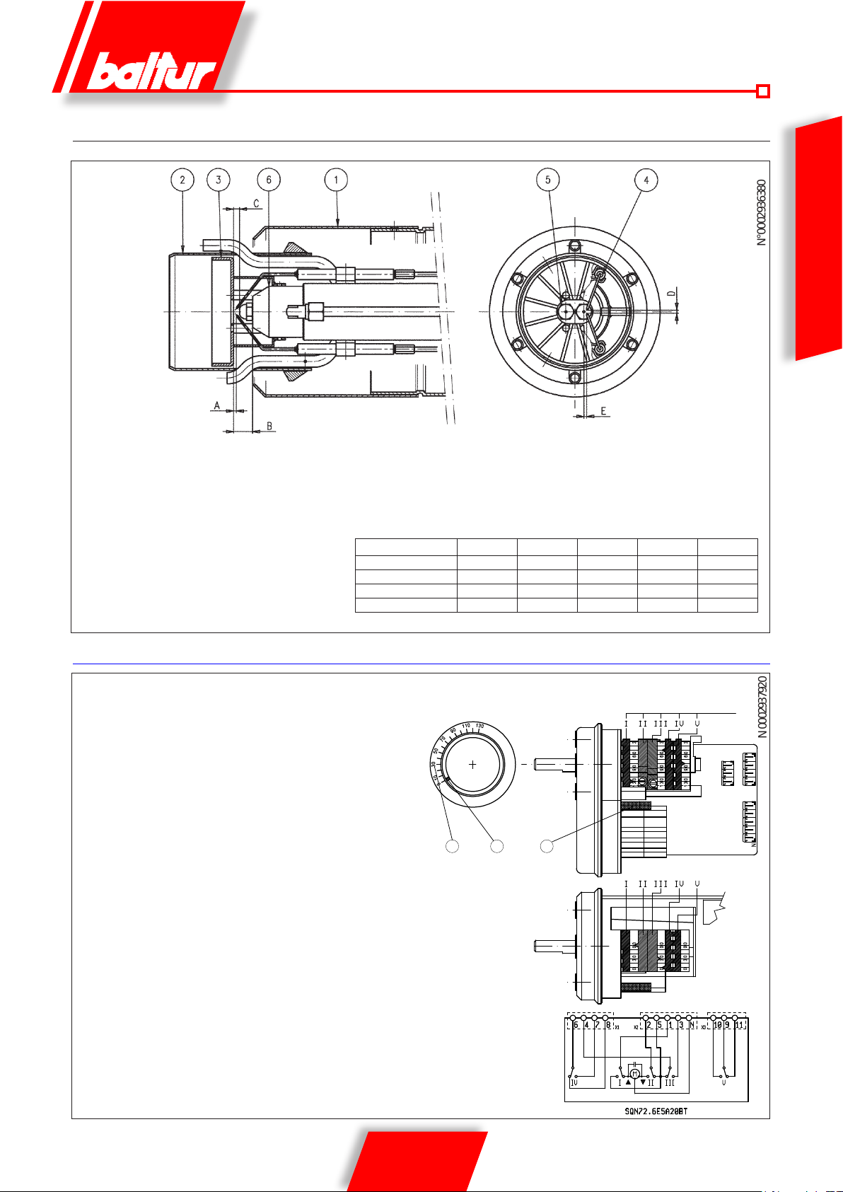
N°0002936380
N 0002937920
SCHEMA REGOLAZIONE DISCO / ELETTRODI
1- Diffusore
2- Diffusore interno
3 - Disco fiamma
4 - Elettrodi di accensione
5- Ugelli
6- Canotto porta ugelli
ITALIANO
Dopo aver montato gli ugelli, verificare il corretto posizionamento di elettrodi e
disco, secondo le quote indicate in mm.
E’ opportuno eseguire una verifica delle quote dopo ogni intervento sulla testa.
UGELLI CONSIGLIATI: STEINEN tipo SS 45° (TBML 80 MC - 120 MC - 200MC)
MONARCH tipo HV 45° (TBML 160 MC)
A B C D E
TBML 80 MC 1 ÷ 1,5 20 ÷ 21 6 ÷ 7 3 ÷ 4 5 ÷ 6
TBML 120 MC 1 ÷ 1,5 20 ÷ 21 6 ÷ 7 3 ÷ 4 8 ÷ 9
TBML 160 MC 1 ÷ 1,5 20 ÷ 21 6 ÷ 7 3 ÷ 4 8 ÷ 9
TBML 200 MC 1 ÷ 1,5 20 ÷ 21 7 ÷ 8 3 ÷ 4 8 ÷ 9
SERVOMOTORI REGOLAZIONE ARIA / COMBUSTIBILE
REGOLAZIONE CAMME SERVOMOTORE SQN72.6E5A20BT
1 Perno di inserzione ed esclusione accoppiamento
motore - albero camme.
2 Scala di riferimento
3 - Indicatore di posizione
2
I Camma regolazione apertura massima aria (130°)
II Chiusura totale aria (bruciatore fermo) (0°)
III Camma regolazione aria per minima gas (30°)
IV Camma regolazione aria 1° fiamma gasolio (50°)
V Camma inserzione valvola 2° fiamma gasolio (maggiore di camma IV) (80°)
Per modificare la regolazione delle camme utilizzate, si agisce sui rispettivi anelli
(I - II - III....). L’indice dell’anello indica sulla rispettiva scala di riferimento l’angolo
di rotazione impostato per ogni camma.
1
CAMME REGOLABILI
3
25 / 36
0006081544_201408
Page 28
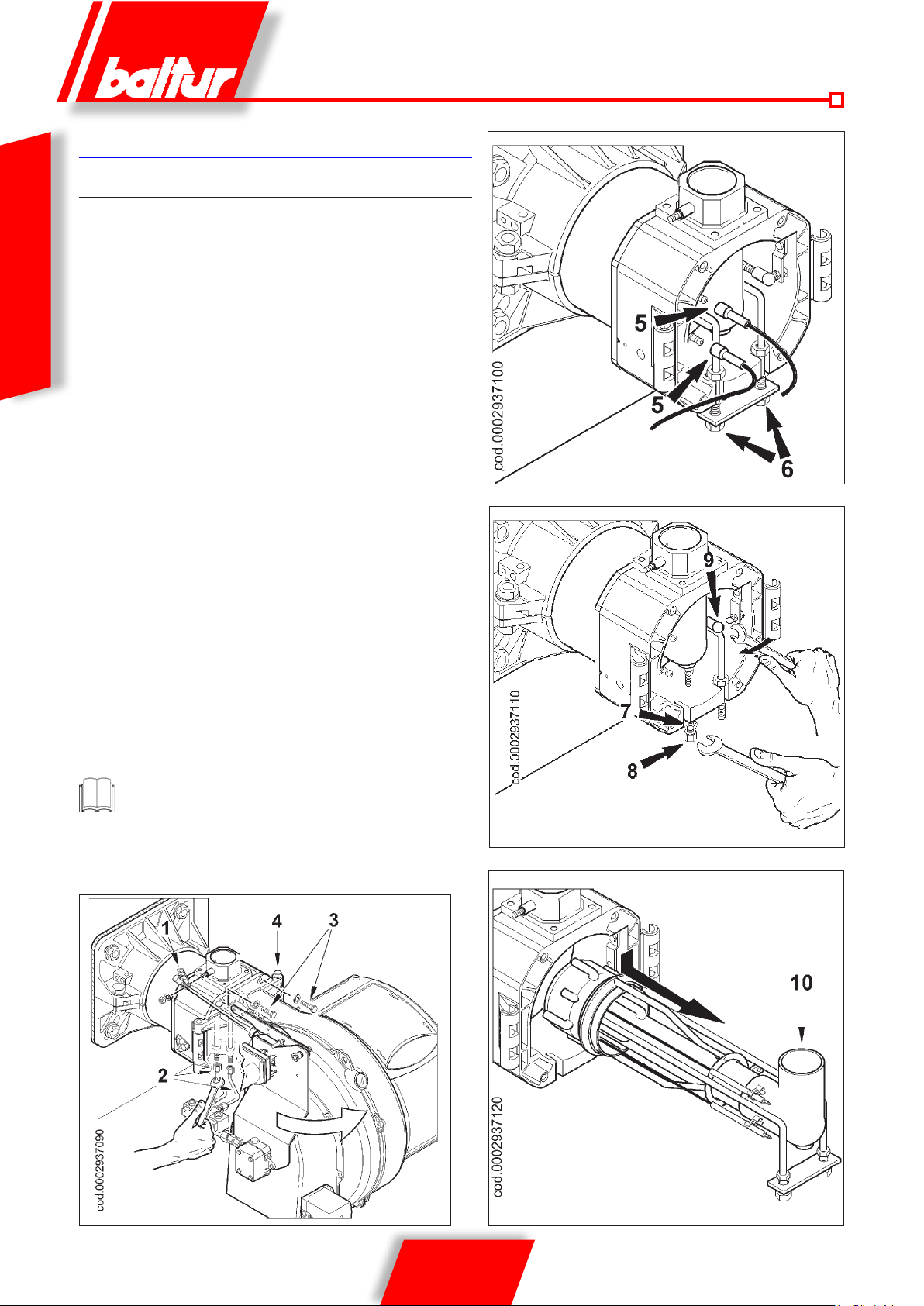
MANUTENZIONE
TBML 80 MC
Effettuare almeno una volta all’anno e comunque in conformità alle
norme vigenti, l’analisi dei gas di scarico della combustione verificando
la correttezza dei valori di emissioni.
• Controllare il ltro del combustibile, se è sporco sostituirlo.
• Vericare che tutti i componenti della testa di combustione siano
ITALIANO
in buono stato, non deformati dalla temperatura e privi di impurità
o depositi derivanti dall’ambiente di installazione o da una cattiva
combustione, controllare l’efcienza degli elettrodi.
• Nel caso si renda necessaria la pulizia della testa di combustione,
estrarne i componenti seguendo la procedura sotto indicata:
- Togliere il dado di ssaggio e sganciare la leva comando farfalla
gas (1).
- Scollegare i tubini gasolio (2) dai raccordi posti sotto il Gruppo
Testa (attenzione al gocciolamento).
- Svitare le due viti (N.3) e ruotare il bruciatore attorno al perno 4
inlato nell’apposita cerniera.
- Dopo aver slato i cavi di accensione (5) dai rispettivi elettrodi,
allentare i due dadi di bloccaggio (6) dal gruppo di miscelazione.
A questo punto allentare il dado (7) e svitare completamente la
vite ssaggio raccordo mandata (8). Utilizzando la stessa chiave
agire sullo snodo sferico (9) nella direzione indicata dalla freccia
sganciando la leva di avanzamento della testa di combustione.
- Abbassare leggermente il raccordo mandata gas (10).e slare
l’intero gruppo di miscelazione nella direzione indicata dalla
freccia di gura 4.
- Completare le operazioni di manutenzione procedendo con il
rimontaggio della testa di combustione seguendo a ritroso il per-
corso sopra descritto e dopo aver vericato la corretta posizione
degli elettrodi di accensione (Vedi 0002936380).
All’atto della chiusura del bruciatore, tirare delicatamente verso
il quadro elettrico, mettendoli in leggera tensione, i due cavi di
accensione, quindi sistemarli nelle apposite sedi sulla chiocciola.
Questo eviterà che i due cavi vengano danneggiati dalla ventola
durante il funzionamento del bruciatore.
26 / 36
0006081544_201408
Page 29
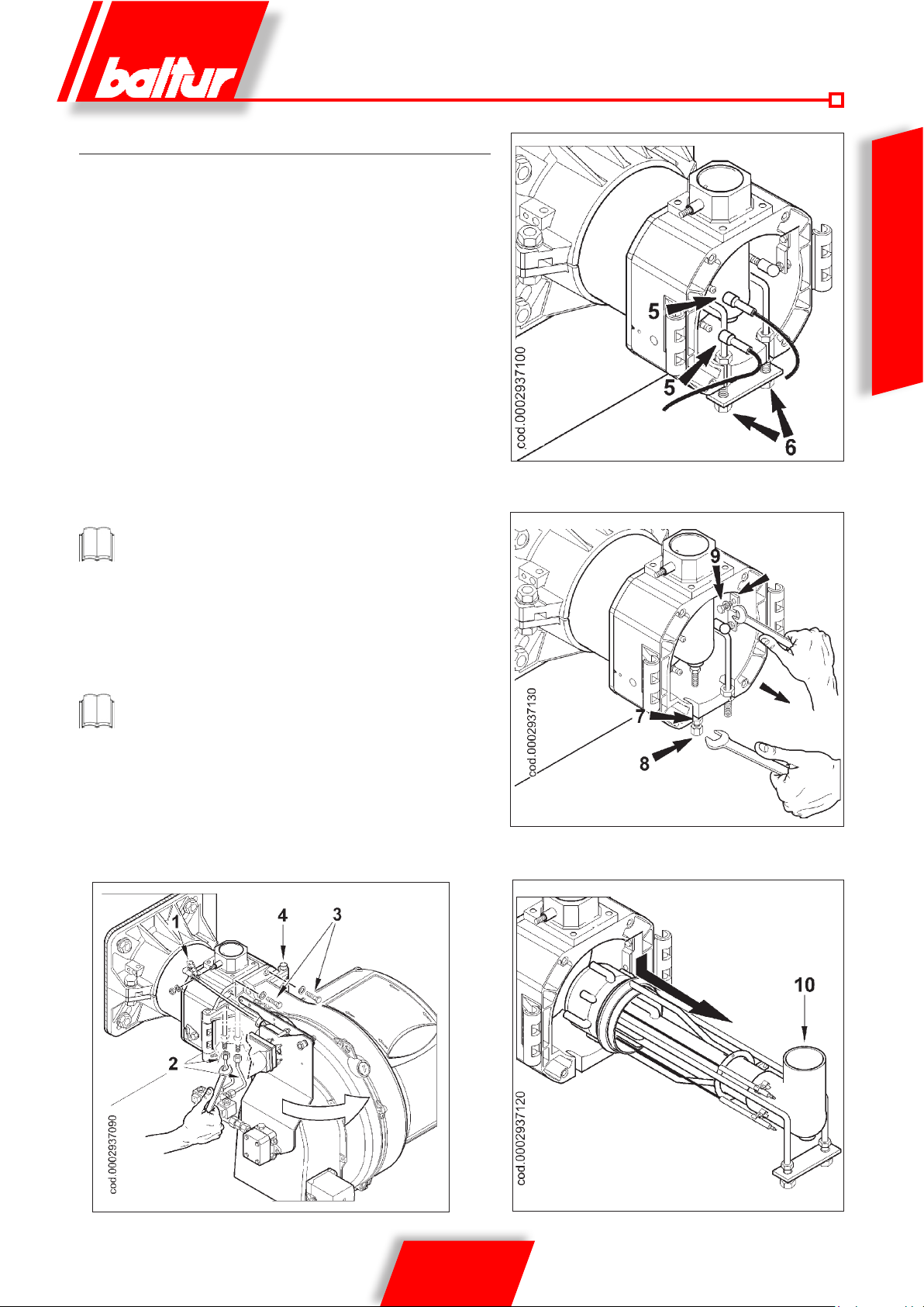
TBML 120 / 160 / 200 MC
Effettuare almeno una volta all’anno e comunque in conformità alle
norme vigenti, l’analisi dei gas di scarico della combustione verificando la
correttezza dei valori di emissioni.
Verificare che tutti i componenti della testa di combustione siano in buono
stato, non deformati dalla temperatura e privi di impurità o depositi derivanti
dall’ambiente di installazione o da una cattiva combustione, controllare
l’efficienza degli elettrodi.
Nel caso si renda necessaria la pulizia della testa di combustione, estrarne
i componenti seguendo la procedura sotto indicata:
• Togliere il dado di ssaggio e sganciare la leva comando farfalla gas (1).
• Scollegare i tubini gasolio (2) dai raccordi posti sotto il GruppoTesta
(attenzione al gocciolamento)
• Svitare le due viti (3) e ruotare il bruciatore attorno al perno (4) inlato
nell’apposita cerniera.
• Dopo aver slato i cavi di accensione (5) dai rispettivi elettrodi, allentare
i due dadi di bloccaggio (6) dal gruppo di miscelazione. A questo punto
allentare il dado (7) e svitare completamente la vite ssaggio raccordo
mandata (8). Utilizzando la chiave idonea svitare la vite (9) e sganciare
la leva di avanzamento della testa di combustione (vedi g. 3).
Nel buriciatore TBML 200 MC non è necessario sganciare la leva
regolazione testa.
• Abbassare leggermente il raccordo mandata gas (10) e slare l’intero
gruppo di miscelazione nella direzione indicata dalla freccia di gura 4.
• Completare le operazioni di manutenzione procedendo con il rimontaggio della testa di combustione seguendo a ritroso il percorso sopra
descritto e dopo aver vericato la corretta posizione degli elettrodi di
accensione (Vedi 0002936380).
All’atto della chiusura del bruciatore, tirare delicatamente verso
il quadro elettrico, mettendoli in leggera tensione, i due cavi di
accensione, quindi sistemarli nelle apposite sedi sulla chiocciola.
Questo eviterà che i due cavi vengano danneggiati dalla ventola
durante il funzionamento del bruciatore.
figura-2
ITALIANO
figura-3
gura 1
27 / 36
0006081544_201408
figura-4
Page 30

PRECISAZIONI SULL’USO DEL
PROPANO
• Valutazione, indicativa, del costo di esercizio
3
- 1 m
di gas liquido in fase gassosa ha un potere calorico
inferiore, di circa 25,6 kW.
- Per ottenere 1 m3 di gas occorrono circa 2 Kg di gas liquido
che corrispondono a circa 4 litri di gas liquido.
Da quanto sopra esposto si può dedurre che utilizzando gas liquido
ITALIANO
(G.P.L.) si ha indicativamente la seguente equivalenza: 25,6 kW= 1
m3 (in fase gassosa) = 2 kg di G.P .L. (liquido) = 4 litri G.P.L. (liquido)
da cui è possibile valutare il costo di esercizio.
• Disposizione di sicurezza
Il gas liquido (G.P.L.) ha, in fase gassosa, un peso spe-
cifico superiore a quello dell’aria (peso specifico relativo
all’aria = 1,56 per il propano) e quindi non si disperde come il metano
che ha un peso specico inferiore (peso specico relativo all’aria =
0,60 per il metano), ma precipita e si spande al suolo (come fosse
un liquido). Il Ministero Dell’Interno pertanto ha disposto limitazioni
nell’impiego del gas liquido con la circolare n° 4 12/4183 del 6 Feb-
braio 1975 di cui riassumiamo i concetti che riteniamo più importanti.
- L’utilizzo del gas liquido (G.P.L.) bruciatore e/o caldaia può
avvenire solo in locali fuori terra e attestati verso spazi liberi.
Non sono ammesse installazioni che utilizzano il gas liquido
in locali seminterrati o interrati.
- I loc ali dove si utiliz za gas li quido devono avere aper ture di
ventilazione prive di dispositivo di chiusura ricavate su pareti
esterne con supercie pari almeno ad 1/15 della supercie in
pianta del locale, con un minimo di 0,5 m2. Di dette aperture
almeno un terzo della supercie complessiva deve essere
posta nella parte inferiore di parete esterna a lo pavimento.
• Esecuzioni dell’impianto del gas liquido per assicurare corretto
funzionamento e sicurezza. La gassicazione naturale, da
batteria di bombole o serbatoio, è utilizzabile solo per impianti
di piccola potenza. L a capacità di erogazi one in fase di gas,
in funzione delle dimensioni del se r batoio e della tem peratur a
minima esterna sono esposte, sol o a titolo indicativo, nella
seguente tabella.
• Bruciatore
Il bruciatore deve essere richiesto specicatamente per l’uso
di gas liquido (G.P.L.) afnché sia dotato di valvole gas di di-
mensioni adatte per ottenere accensione corretta e regolazione
graduale. Il dimensionamento delle valvole è da noi previsto per
la pressione di alimentazione di circa 300 mm C.A. Consigliamo
di vericare la pressione del gas al bruciatore mediante manometro a colonna d’acqua.
La potenza massima e minima del bruciatore, è considerata
con combustibile metano. Il G.P.L. ha un potere calorifico
superiore a quello del metano, pertanto, per una combustione
corretta, richiede quantità di aria proporzionale alla potenza
termica sviluppata.
I bruciatori TBML...MC e ME possono funzionare a GPL senza
alcun intervento sulla testa di combustione
• Controllo combustione
Per Contenere i consumi e principalme nte per evitare gravi
inconvenienti, regolare la combustione impiegando gli appositi
strumenti. E’ assolutamente indispensabile accertare che la percentuale di ossido di carbonio (CO) non superi il valore massimo
ammesso dello 0,1 % (impiegare l’analizzatore di combustione).
Sono esclusi dalla garanzia i bruciatori fonzionanti a gas
liquido (G.P.L.) in impianti dove non siano state adottate le
disposizioni sopra esposte..
Temperatura
minima
Serbatoio 990 l. 1,6 Kg/h 2,5 Kg/h 3,5 Kg/h 8 Kg/h 10 Kg/h
Serbatoio 3000 l. 2,5 Kg/h 4,5 Kg/h 6,5 Kg/h 9 Kg/h 12 Kg/h
Serbatoio 5000 l. 4 Kg/h 6,5 Kg/h 11,5 Kg/h 16 Kg/h 21 Kg/h
- 15 °C - 10 °C - 5 °C - 0 °C + 5 °C
28 / 36
0006081544_201408
Page 31
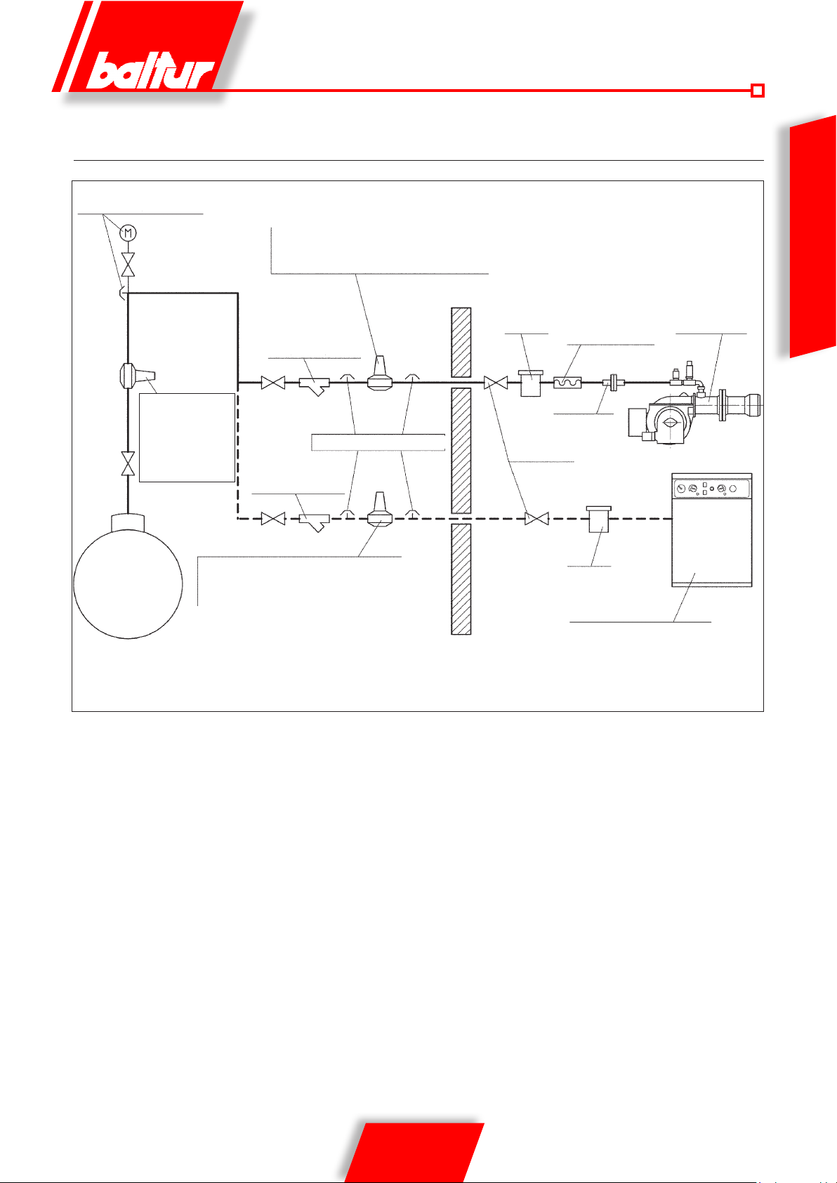
SCHEMA DI PRINCIPIO PER RIDUZIONE PRESSIONE G.P.L.
A DUE SALTI PER BRUCIATORE O CALDAIA
Manometro e presa di pressione
Riduttore di
1° salto;
Uscita = ~ 1 bar
Portata =
adeguata
Riduttore di 2° salto;
Serbatoio
Uscita = ~ 30 mbar
Portata = circa il doppio del massimo
richiesto dall’utilizzatore
Riduttore di 2° salto;
Uscita = ~ 30 mbar
Portata = circa il doppio del massimo richiesto dall’utilizzatore
Filtro
Filtro (tipo vapore)
(presa di pressione)
Filtro (tipo vapore)
8721/2
ITALIANO
Bruciatore
Giunto antivibrante
Raccordo
Rubinetto
Filtro
Caldaia (a pavimento o murale)
Nota: Non coprire con materiale isolante tubazioni e riduttori.
29 / 36
0006081544_201408
Page 32

ISTRUZIONI PER L’ACCERTAMENTO DELLE CAUSE DI IRREGOLARITÀ’
NEL FUNZIONAMENTO E LORO ELIMINAZIONE
NATURA IRREGOLARITÀ’ CAUSA POSSIBILE RIMEDIO
Bruciatore che non si avvia.
(l’apparecchiatura non effettua il programma di accensione)
ITALIANO
Fiamma difettosa con presenza di
faville.
Fiamma non ben conformata con fumo
e fuliggine.
Fiamma difettosa, pulsante, o sfuggente dalla bocca di combustione.
Corrosioni interne nella caldaia. 1) Temperatura di esercizio della caldaia troppo
1) Termostati (caldaia o ambiente) o pressostati, aperti
2) Fotoresistenza in corto circuito
3) Manca la tensione per interruttore generale
aperto o interruttore di massima del contatore
scattato o mancanza di tensione in linea
4) La linea dei termostati non è stata eseguita
secondo schema o qualche termostato è
rimasto aperto
5) Guasto interno all’apparecchiatura
1) Pressione di polverizzazione troppo bassa
2) Eccesso di aria comburente
3) Ugello inefciente perché sporco o logoro
4) Acqua nel combustibile
1) Insufcienza di aria comburente
2) Ugello inefciente perché sporco o logoro
3) Camera di combustione di forma non adatta
o troppo piccola
4) Ugello di portata insufficiente rispetto al
volume della camera di combustione
5) Rivestimento refrattario non adatto (riduce
eccessivamente lo spazio per la amma)
6) Condotti della caldaia o camino ostruiti
7) Pressione di polverizzazione bassa
1) Tiraggio eccessivo (solo in
caso di un aspiratore al camino)
2) Ugello inefciente perché sporco o logoro
3) Presenza di acqua nel combustibile
4) Disco sporco
5) Eccesso di aria di combustione
6) Passaggio dell’aria tra disco e bocca eccessivamente chiuso
bassa (inferiore al punto di rugiada)
2) Temperatura dei fumi troppo bassa, indicativamente al di sotto dei 130 °C per gasolio.
1) Alzarne il valore o attendere che si chiudano
per diminuzione naturale della temperatura
o pressione
2) Sostituirla
3) Chiudere gli interruttori o attendere il ritorno
della tensione
4) Controllare collegamenti e termostati
5) Sostituirla
1) Ripristinarla al valore previsto
2) Diminuire l’aria di combustione
3) Pulirlo o sostituirlo
4) Scaricarla dalla cisterna servendosi di una
pompa adatta. (Non usare mai per questo
lavoro la pompa del bruciatore)
1) Aumentare l’aria di combustione
2) Pulirlo o sostituirlo
3) Diminuire la portata di gasolio in rapporto
alla camera di combustione (ovviamente la
potenza termica esagerata risulterà inferiore
a quella necessaria) o sostituire la caldaia
4) Aumentare la portata dell’ugello sostituendolo
5) Modificarlo attenendosi alle istruzioni del
costruttore della caldaia
6) Provvedere alla loro pulizia
7) Provvedere a riportarla al valore prescritto
1) Adeguare la velocità dell’aspirazione modicando i diametri delle pulegge
2) Pulirlo o sostituirlo
3) Eliminarla dalla cisterna con l’aiuto di una
pompa adatta (non usare mai per questa
operazione la pompa del bruciatore)
4) Pulirlo
5) Ridurre l’aria di combustione
6) Correggere la posizione del dispositivo di
regolazione della testa di combustione.
1) Aumentare la temperatura di esercizio
2) Aumentare la portata di gasolio se la caldaia
lo consente.
Fuliggine allo sbocco del camino. 1) Eccessivo raffreddamento (indicativamente
al di sotto dei 130°C) dei fumi prima dello
sbocco, per camino esterno, non sufcien-
temente coibentato oppure per inltrazioni
di aria fredda
30 / 36
0006081544_201408
1) Migliorare l’isolamento ed eliminare ogni
apertura che possa consentire l’ingresso di
aria fredda al camino.
Page 33

ISTRUZIONI PER L’ACCERTAMENTO DELLE CAUSE DI IRREGOLARITÀ’ NEL
FUNZIONAMENTO DEI BRUCIATORI E LORO ELIMINAZIONE
NATURA IRREGOLARITÀ’ CAUSA POSSIBILE RIMEDIO
L’apparecchio va in blocco con la amma
(lampada rossa accesa) il guasto è circo-
scritto al dispositivo di controllo amma.
1)Fotoresistenza interrotta o sporca di fumo
2) Tiraggio insufciente
3) Circuito del rilevatore amma interrotto
nell’apparecchiatura
4) Disco o bocca sporchi
1) Pulirla o sostituirla
2) Controllare tutti i passaggi dei fumi nella
caldaia e nel camino
3) Sostituire l’apparecchiatura
4) Pulire
ITALIANO
L’apparecchio va in blocco spruzzando
combustibile liquido senza il vericarsi
della fiamma (lampada rossa accesa).
Il guasto è circoscritto al dispositivo di
accensione, ammesso che il combustibile
sia in buone condizioni (non inquinato da
acqua o altro) e sufcientemente polverizzato.
L’apparecchio và in “blocco”, il gas esce,
ma la amma non è presente (lampada
rossa accesa). Guasto circoscritto al circuito di accensione.
L’apparecchio va in blocco spruzzando
combustibile liquido senza il vericarsi
della amma. (Lampada rossa accesa).
L’apparecchio và in “blocco”, il gas esce,
ma la amma non è presente (lampada
rossa accesa).
1) Interruzione nel circuito di accensione.
2) I cavetti del trasformatore di accensione
scaricano a massa.
3) I cavetti del trasformatore di accensione
non sono ben collegati.
4) Trasformatore d’accensione guasto.
5) Le punte degli elettrodi non sono alla giusta
distanza.
6) Gli elettrodi scaricano a massa perché
sporchi o per isolante incrinato; controllare
anche sotto i morsetti di ssaggio degli
isolantori di porcellana.
1) La pressione della pompa non è regolare
2) Presenza di acqua nel combustibile
3) Eccesso di aria di combustione
4) Passaggio dell’aria tra disco e bocca eccessivamente chiuso
5) Ugello logoro o sporco
1) Rapporto aria / gas non corretto.
2) La tubazione del gas non è stata adeguatamento sfogat a dell’aria (caso di prima
accensione).
3) La pressione de l gas è insufficiente o
eccessiva.
4) Passaggio aria tra di sco e testa troppo
chiuso.
1) Vericare tutto il circuito
2) Sostituirli
3) Collegarli
4) Sostituirlo
5) Riportare nella posizione prescritta
6) Pulirli o, se necessario, sostituirli
1) Regolarla
2) Eliminarla dalla cisterna con l’aiuto di una
pompa adatta (non usare mai per questa
operazione la pompa del bruciatore)
3) Ridurre l’aria di combustione
4) Correggere la posizione di regolazione della
testa di combustione
5) Sostituirlo o pulirlo
1) Correggere il rapporto aria / gas.
2) Sfogare ulteri or mente c on le dov ute ca utele, la tubazione del gas.
3) Vericare il valore della pressione gas
al momento dell’accensione (us are un
manometro ad acqua possibilmente)
4) Adeguare l’apertura disco / testa.
Pompa del bruciatore rumorosa. 1) Tubazione di diametro troppo piccolo
2) Inltrazioni d’aria nei tubi
3) Filtro sgrossatore sporco
4) Distanza e/o dislivello negativo eccessivi fra
cisterna e bruciatore oppure molte perdite
accidentali (curve, gomiti, strozzature ecc.)
5) Tubi essibili deteriorati
31 / 36
0006081544_201408
1) Sostituirla attenendosi alle relative istruzioni
2) Vericare ed eliminare tali inltrazioni
3) Smontarlo e lavarlo
4) Retticare l’intero sviluppo del tubo di aspirazione riducendo così la distanza
5) Sostituirli
Page 34

TABELLA PORTATA UGELLI
Ugello
G.P.H.
0,40 1,27 1,36 1,44 1,52 1,59 1,67 1,73 1,80 1,86 1,92 1,98 2,04 2,10 2,15 2,20 0,40
0,50 1,59 1,70 1,80 1,90 1,99 2,08 2,17 2,25 2,33 2,40 2,48 2,55 2,62 2,69 2,75 0,50
0,60 1,91 2,04 2,16 2,28 2,39 2,50 2,60 2,70 2,79 2,88 2,97 3,06 3,14 3,22 3,30 0,60
ITALIANO
0,65 2,07 2,21 2,34 2,47 2,59 2,71 2,82 2,92 3,03 3,12 3,22 3,31 3,41 3,49 3,58 0,65
0,75 2,38 2,55 2,70 2,85 2,99 3,12 3,25 3,37 3,49 3,61 3,72 3,82 3,93 4,03 4,13 0,75
0,85 2,70 2,89 3,06 3,23 3,39 3,54 3,68 3,82 3,96 4,09 4,21 4,33 4,45 4,57 4,68 0,85
1,00 3,18 3,40 3,61 3,80 3,99 4,16 4,33 4,50 4,65 4,81
1,10 3,50 3,74 3,97 4,18 4,38 4,58 4,77 4,95 5,12 5,29 5,45 5,61 5,76 5,91 6,06 1,10
1,20 3,82 4,08 4,33 4,56 4,78 5,00 5,20 5,40 5,59 5,77 5,95 6,12 6,29 6,45 6,61 1,20
1,25 3,97 4,25 4,50 4,75 5,00 5,20 5,40 5,60 5,80 6,00 6,20 6,35 6,55 6,70 6,85 1,25
1,35 4,29 4,59 4,87 5,13 5,38 5,62 5,85 6,07 6,28 6,49 6,69 6,88 7,07 7,26 7,44 1,35
1,50 4,77 5,10 5,41 5,70 5,90 6,24 6,50 6,75 6,98 7,21 7,43 7,65 7,86 8,06 8,26 1,50
1,65 5,25 5,61 5,95 6,27 6,58 6,87 7,15 7,42 7,68 7,93 8,18 8,41 8,64 8,87 9,09 1,65
1,75 5,56 5,95 6,31 6,65 6,98 7,29 7,58 7,87 8,15 8,41 8,67 8,92 9,17 9,41 9,64 1,75
2,00 6,30 6,80 7,21 7,60 7,97 8,33 8,67 8,99
2,25 7,15 7,65 8,15 8,55 8,97 9,37 9,75 10,12 10,47 10,85 11,15 11,47 11,79 12,09 12,39 2,25
2,50 7,95 8,50 9,01 9,50 9,97 10,41 10,83 11,24 11,64 12,02 12,39 12,75 13,10 13,44 13,77 2,50
3,00 9,54 10,20 10,82 11,40 11,96 12,49 13,00 13,49 13,96 14,02 14,87 15,30 15,72 16,12 16,52 3,00
3,50 11,13 11,90 12,62 13,30 13,95 14,57 15,17 15,74 16,29 16,83 17,34 17,85 18,34 18,81 19,28 3,50
4,00 12,72 13,60 14,42 15,20 15,94 16,65 17,33 17,99 18,62 19,23 19,82 20,40 20,95 21,50 22,03 4,00
4,50 14,31 15,30 16,22 17,10 17,94 18,73 19,50 20,24 20,95 21,63 22,30 22,95 23,57 24,19 24,78 4,50
5,00 15,90 17,00 18,03 19,00 19,93 20,82 21,67 22,48 23,27 24,04 24,78 25,49 26,19 26,87 27,54 5,00
5,50 17,49 18,70 19,83 20,90 21,92 22,90
6,00 19,00 20,40 21,63 22,80 23,92 24,98 26,00 26,98 27,93 28,84 29,73 30,59 31,43 32,25 33,04 6,00
6,50 20,67 22,10 23,44 23,70 25,91 27,06 28,17 29,23 30,26 31,25 32,21 33,14 34,05 34,94 35,80 6,50
7,00 22,26 23,79 25,24 26,60 27,90 29,14 30,33 31,48 32,58 33,65 34,69 35,69 36,67 37,62 38,55 7,00
7,50 23,85 25,49 27,04 28,50 29,90 31,22 32,50 33,73 34,91 36,05 37,16 38,24 39,29 40,31 41,31 7,50
8,30 26,39 28,21 29,93 31,54 33,08 34,55 35,97 37,32 38,63 39,90 41,13 42,32 43,48 44,61 45,71 8,30
9,50 30,21 32,29 34,25 36,10 37,87 39,55 41,17 42,72 44,22 45,67 47,07 48,44 49,77 51,06 52,32 9,50
10,50 33,39 35,69 37,86 40,06 41,73 43,74 45,41 47,20 48,90 50,50 52,00 53,50 55,00 56,40 57,80 10,50
12,00 38,20 40,80 43,30 45,60
13,80 43,90 46,90 49,80 52,40 55,00 57,50 59,80 62,10 64,20 66,30 68,40 70,40 72,30 74,30 76,00 13,80
15,30 48,60 52,00 55,20 58,10 61,00 63,70 66,30 68,80 71,10 73,60 75,80 78,00 80,20 82,20 84,30 15,30
17,50 55,60 59,50 63,10 66,50 69,80 72,90 75,80 78,70 81,50 84,10 86,70 89,20 91,70 94,10 96,40 17,50
19,50 62,00 66,30 70,30 74,10 77,70 81,20 84,50 87,70 90,80 93,70 96,60 99,40 102,20 104,80 107,40 19,50
21,50 68,40 73,10 77,50 81,70 85,70 89,50 93,20 96,70 100,10 103,40 106,50 109,60 112,60 115,60 118,40 21,50
24,00 76,30 81,60 86,50 91,20 95,70 99,90 104,00 107,90 111,70 115,40 118,90 122,40 125,70 129,00 132,20 24,00
28,00 89,00 95,20 101,00 106,40 111,60 116,60 121,30 125,90 130,30 134,60 138,70 142,80 146,70 150,50 154,20 28,00
30,00 95,40 102,00
Pressione pompa
7 8 9 10 11 12 13 14 15 16 17 18 19 20 21
Portata all’uscita dell’ugello
4,96 5,10 5,24 5,37 5,51 1,00
9,31 9,61 9,91 10,20 10,48 10,75 11,01 2,00
23,83 24,73 25,60 26,44 27,25 28,04 28,81 29,56 30,29 5,50
47,80 50,00 52,00 54,00 55,90 57,70 59,50 61,20 62,90 64,50 66,10 12,00
108,20 114,00 119,60 124,90 130,00 134,90 139,60 144,20 148,70 153,00 157,20 161,20 165,20 30,00
Ugello
G.P.H.
1 mbar = 10 mmC.A. 100 Pa
1 kW = 860 kcal
Densità del gasolio ................................................= 0,820 / 0,830 PCI = 10150
Densità dello special .............................................. = 0,900 PCI = 9920
Densità del domestico (3,5°E) ...............................= 0,940 PCI = 9700
Densità del denso (7,9°E) .....................................= 0,970 / 0,980 PCI = 9650
PCI = Potere Calorico Inferiore
32 / 36
0006081544_201408
Page 35
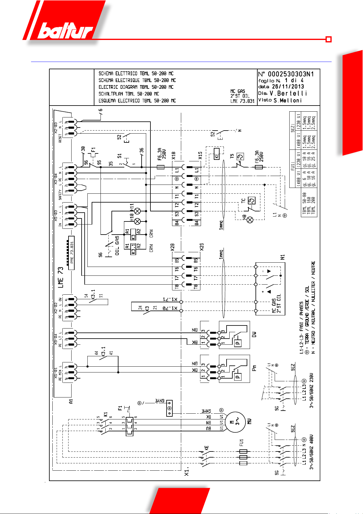
SCHEMA ELETTRICO
ITALIANO
33 / 36
0006081544_201408
Page 36
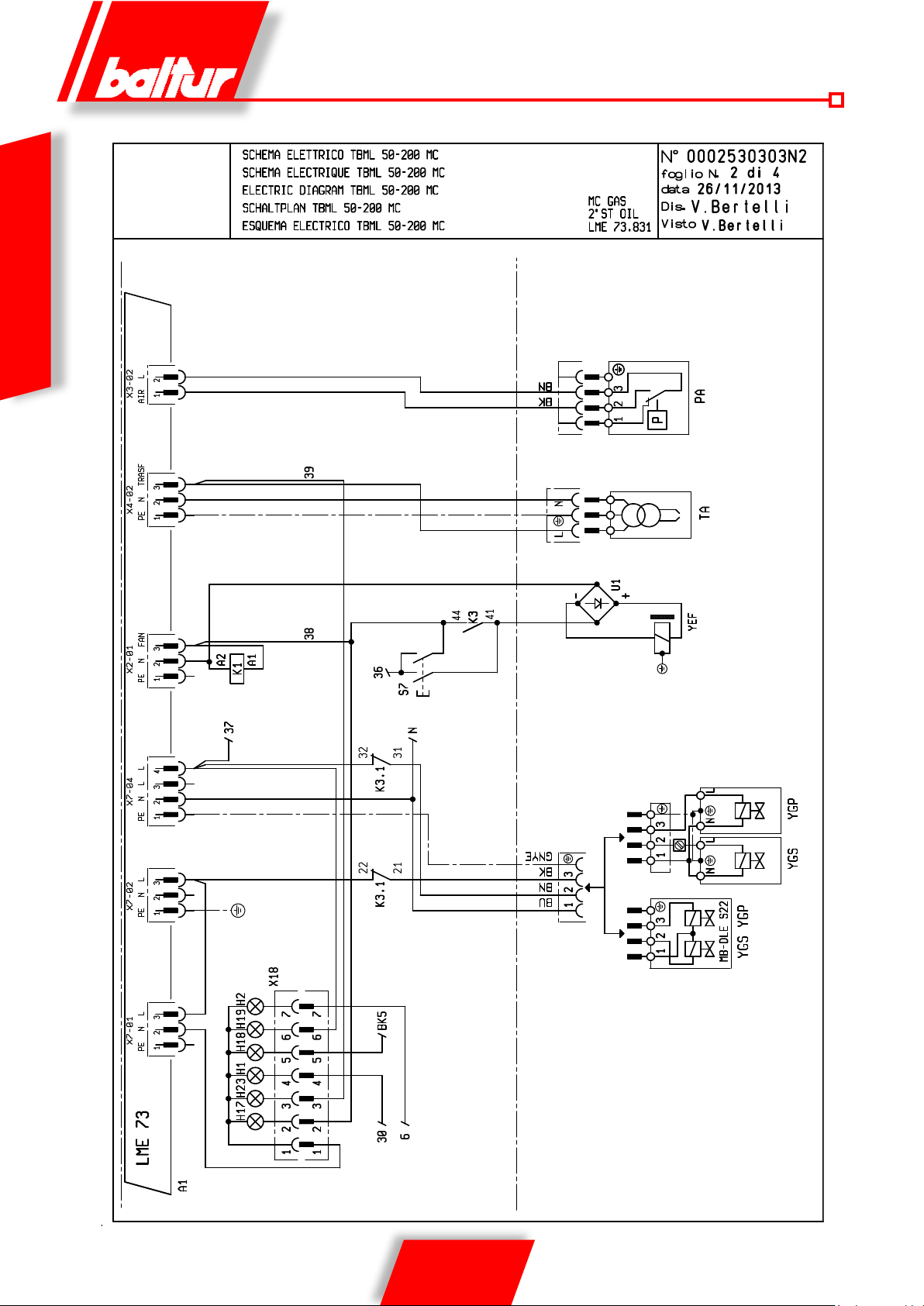
ITALIANO
34 / 36
0006081544_201408
Page 37
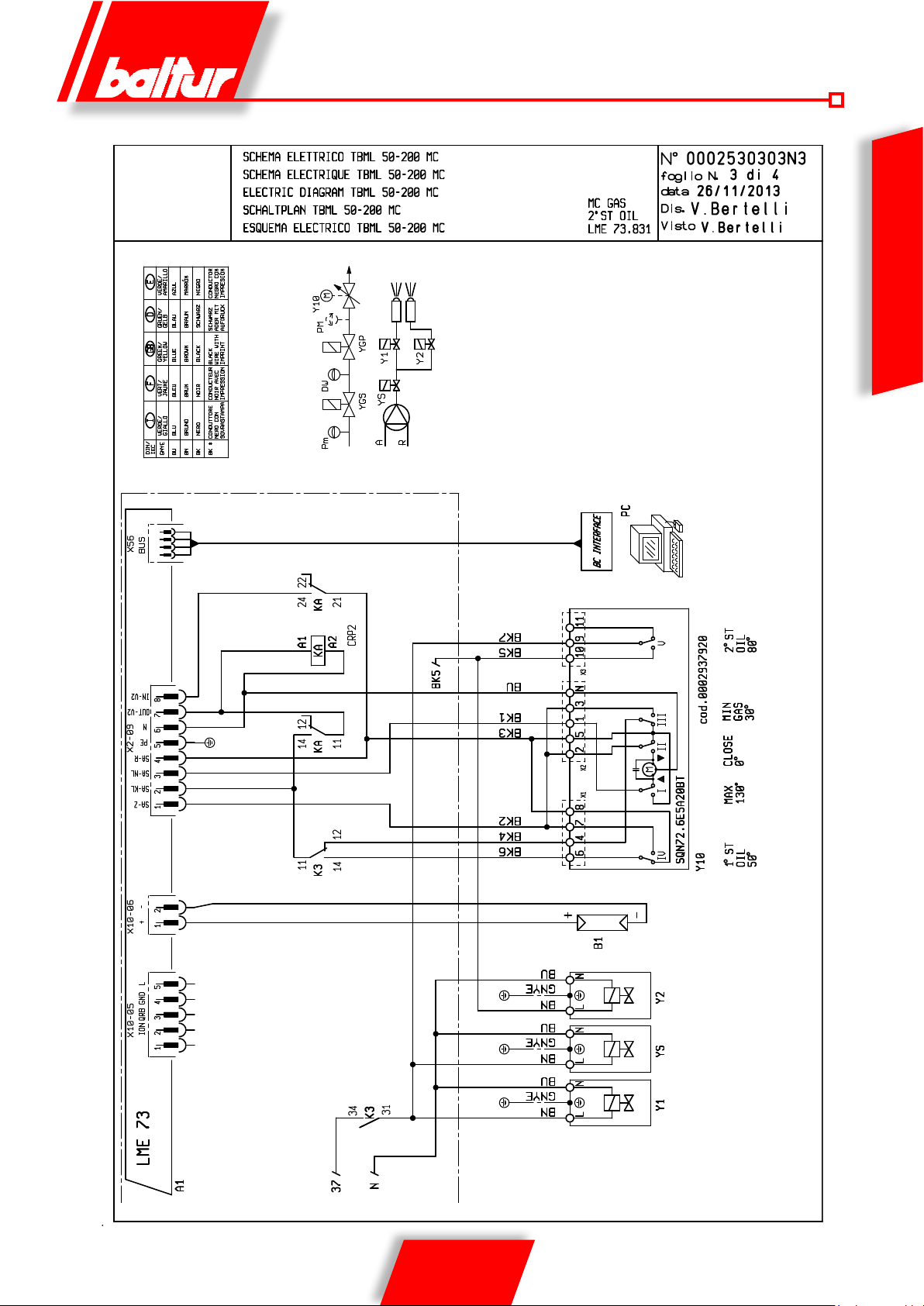
ITALIANO
35 / 36
0006081544_201408
Page 38

A1 APPARECCHIATURA
B1 FOTOCELLULA UV
DW PRESSOSTATO DI CONTROLLO TENUTA VALVOLE
F1 RELE’ TERMICO
FU1 FUSIBILI
H0 SPIA BLOCCO ESTERNA
ITALIANO
H1 SPIA DI FUNZIONAMENTO
H10 SPIA FUNZIONAMENTO OLIO
H11 SPIA FUNZIONAMENTO GAS
H17 SPIA FUNZIONAMENTO VENTILATORE
H18 SPIA FUNZIONAMENTO 2° STADIO
H19 SPIA FUNZIONAMENTO VALVOLE PRINCIPALI
H2 SPIA DI BLOCCO
H23 SPIA FUNZIONAMENTO TRASFORMATORE
K1 RELE’ MOTORE
K3-3.1 RELE’ CAMBIO COMBUSTIBILE
KA RELE’ AUSILIARIO
KE CONTATTORE ESTERNO
MV MOTORE VENTOLA
PA PRESSOSTATO ARIA
Pm PRESSOSTATO DI MINIMA
S1 INTERRUTTORE MARCIA ARRESTO
S2 PULSANTE SBLOCCO
S6 SELETTORE GAS-OLIO
S7 PULSANTE CARICAMENTO SERBATOIO
SG INTERRUTTORE GENERALE
T2 TERMOSTATO 2 STADIO
TA TRASFORMATORE D’ACCENSIONE
TC TERMOSTATO CALDAIA
TS TERMOSTATO DI SICUREZZA
X1B/S CONNETTORE ALIMENTAZIONE
X2B/S CONNETTORE 2° STADIO
X18 CONNETTORE SINOTTICO
Y1 ELETTROVALVOLA 1° STADIO
Y2 ELETTROVALVOLA 2° STADIO
Y10 SERVOMOTORE ARIA
YEF ELETTROFRIZIONE
YGP ELETTROVALVOLA PRINCIPALE
YGS ELETTROVALVOLA DI SICUREZZA
Z1 FILTRO
IT
DIN / IEC IT
GNYE VERDE / GIALLO
BU BLU
BN BRUNO
BK NERO
BK* CONNETTORE NERO CON SOVRASTAMPA
36 / 36
0006081544_201408
Page 39
• Before starting to use the burner, read the chapter “WARNING NOTES FOR THE USER: HOW TO USE THE BURNER SAFELY” in
We hereby declare under our own responsibility, that our domestic and industrial
blown air burners fired by gas, oil and dual fuel series:
BPM...; BGN…; BT…; BTG…; BTL…; TBML...; Comist…; GI…; GI…Mist;
Minicomist…; PYR…; RiNOx…; Spark...; Sparkgas...; TBG...;TBL...; TS…;
IBR...; IB...
(Variant: … LX, with low NOx emissions)
respect the minimal regulation of the European Directives:
• 2009/142/EC (G.A.D)
• 2004/108/EC (E.M.C.)
• 2006/95/EC (L.V.D)
• 2006/42/EC (M.D.)
and have been designed and tested in accordance with the European Standards:
• EN 676 (gas and dual fuel, gas side)
• EN 267 (light oil and dual fuel, oil side)
Cento, 23 July 2013
CE0085:
DVGW CERT GmbH, Josef-Wirmer Strasse 1-3 – 53123 Bonn (D)
Statement of Conformity
CEO and General Manager
Dr. Riccardo Fava
R&D Manager
Eng. Paolo Bolognin
this instruction manual carefully, which is an integral and essential part of the product.
• Carefully read the instructions before starting or maintaining the burner.
• Only skilled personnel is allowed to work on the burner and the system.
• Disconnect the electric power from the system before starting any operation. Wrong operations can lead to dangerous accidents.
DANGER
WARNINGS CAUTION
INFORMATION
ENGLISH
1 / 36
0006081544_201408
Page 40

ENGLISH
TECHNICAL SPECIFICATIONS ....................................................................................................................................................................................... 5
BURNER CONNECTION TO THE BOILER
GAS SUPPLY LINE
DIESEL OIL SUPPLY LINE
SUNTEC PUMP DETAILS
ELECTRICAL CONNECTIONS
COMMAND AND CONTROL EQUIPMENT FOR GAS BURNERS LME 73...
DESCRIPTION OF OPERATION WITH LIQUID FUEL
FIRST FILLING UP OF PIPELINES
IGNITION AND REGULATION
OPERATION DESCRIPTION WITH GASEOUS FUEL
MODULATION OPERATION DESCRIPTION
IGNITION AND ADJUSTMENT WITH METHANE GAS
AIR REGULATION ON THE COMBUSTION HEAD
AIR/FUEL ADJUSTMENT SERVOMOTOR
MAINTENANCE
HOW TO FIND THE CAUSES OF IMPROPER WORKING AND HOW TO RECTIFY THEM
WIRING DIAGRAM
..........................................................................................................................................................................................................10
..............................................................................................................................................................................................11
...............................................................................................................................................................................................14
........................................................................................................................................................................................15
........................................................................................................................................................................................19
..............................................................................................................................................................................................................26
..........................................................................................................................................................................................................31
.....................................................................................................................................................................8
.................................................................................................................16
....................................................................................................................................................17
.................................................................................................................................................................................19
....................................................................................................................................................21
..................................................................................................................................................................21
...................................................................................................................................................22
.........................................................................................................................................................24
......................................................................................................................................................................25
.........................................................................................28
2 / 36
0006081544_201408
Page 41

FOREWORD
These warning notes are aimed at ensuring the safe use of the components of heating systems for civil use and the production of hot water.
They indicate how to act to avoid the essential safety of the components
being compromised by incorrect or erroneous installation and by improper
or unreasonable use. The warning notes provided in this guide also seek
to make the consumer more aware of safety problems in general, using
necessarily technical but easily understood language. The manufacturer
is not liable contractually or extra contractually for any damage caused
by errors in installation and in use, or where there has been any failure to
follow the manufacturer’s instructions.
GENERAL WARNING NOTES
• The instruction booklet is an integral and essential part of the product
• Equipment must be installed in accordance with current regulations,
• After removing all the packaging make sure the contents are complete
• Before carrying out any cleaning or maintenance, switch off the
• If there is any fault or if the equipment is not working properly, de-ac-
• If the equipment is sold or transferred to another owner or if the owner
• For all equipment with optionals or kits (including electrical), only origi-
BURNERS
to boilers, hot air boilers, ovens or other similar equipment and not
exposed to atmospheric agents. Any other use must be regarded as
accordance with current regulations and in any case suf cient to ensure
ventilation openings for the room where a burner or a boiler is installed
spond to those of the utility supplies (electricity, gas, light oil or other
equipment is working and stay hot for some time after the burner has
• Check that the person who carried out the installation of the burner xed
a) Set the burner fuel capacity to the power required by the heat ge-
b) Adjust the combustion air ow to obtain combustion yield of at least
c) Carry out a check on combustion to ensure the production of no-
xious or polluting unburnt gases does not exceed limits permitted
f) Check at the end of the adjustments that all the adjustment devices
g) Make sure that the use and maintenance manual for the burner is
• The running and maintenance of the equipment must only be carried
PRECAUTIONS FOR USE IN CONDITIONS OF SAFETY
• This equipment must be used only for its expressly stated use: applied
and must be given to the user. Carefully read the warnings in the booklet as they contain important information regarding safe installation,
use and maintenance. Keep the booklet to hand for consultation when
needed.
with the manufacturer’s instructions and by quali ed technicians. By
the term ‘quali ed technicians’ is meant persons that are competent in
the eld of heating components for civil use and for the production of
hot water and, in particular, assistance centres authorised by the manufacturer. Incorrect installation may cause damage or injury to persons,
animals or things. The manufacturer will not in such cases be liable.
and intact. If in doubt do not use the equipment and return it to the
supplier. The packaging materials (wooden crates, nails, staples, plastic bags, expanded polystyrene, etc.) must not be left within reach of
children as they may be dangerous to them. They should also be collected and disposed on in suitably prepared places so that they do no
pollute the environment.
equipment at the mains supply, using the system’s switch or shut-off
systems.
improper use and hence dangerous.
• The burner must be installed in a suitable room that has ventilation in
correct combustion
• Do not obstruct or reduce the size of the burner’ air intake grills or the
or dangerous mixtures of toxic and explosive gases may form.
• Before connecting the burner check that the details on the plate correfuel).
• Do not touch hot parts of the burner. These, normally in the areas near
to the ame and any fuel pre-heating system, become hot when the
stopped.
• If it is decided not to use the burner any more, the following actions must
be performed by quali ed technicians:
a) Switch off the electrical supply by disconnecting the power cable from
the master switch.
b) Cut off the fuel supply using the shut-off valve and remove the control
wheels from their position.
c) Render harmless any potentially dangerous parts.
Special warning notes
it securely to the heat generator so that the ame is generated inside
the combustion chamber of the generator itself.
• Before starting up the burner, and at least once a year, have quali ed
technicians perform the following operations:
nerator.
ENGLISH
tivate the equipment and do not attempt to repair it or tamper with it
directly. In such case get in touch with only quali ed technicians. Any
product repairs must only be carried out by BALTUR authorised assistance centres using only original spare parts. Failure to act as above
may jeopardise the safety of the equipment. To ensure the ef ciency
and correct working of the equipment, it is essential to have periodic
maintenance carried out by quali ed technicians following the manufac-
turer’s instructions.
moves and leaves the equipment, make sure that the booklet always
goes with the equipment so it can be consulted by the new owner and/
or installer.
nal accessories must be used.
the minimum set by current regulations.
3 / 36
0006081544_201408
by current regulations.
d) Check the adjustment and safety devices are working properly.
e) Check the ef ciency of the combustion products exhaust duct.
mechanical securing systems are properly tightened.
in the boiler room.
• If the burner repeatedly stops in lock-out, do not keep trying to manually
reset but call a quali ed technicians to sort out the problem.
out by quali ed technicians, in compliance with current regulations.
Page 42

ELECTRICAL SUPPLY
• The equipment is electrically safe only when it is correctly connected to an
ef cient ground connection carried out in accordance with current safety
• Have quali ed technicians check that the wiring is suitable for the
• Adapters, multiple plugs and extension cables may not be used for the
• According to current safety regulations, an omnipolar switch with a contact
• Extract the power cable external insulation as strictly necessary for the
• An ominpolar switch in accordance with current safety regulations is
• The electrical supply to the burner must have neutral to ground
• The use of any components that use electricity means that certain
- do not touch the equipment with parts of the body that are wet or damp
- do not pull on electrical cables
- do not leave the equipment exposed to atmospheric agents (such as
- do not allow the equipment to be used by children or inexpert persons.
• The power supply cable for the equipment not must be replaced by the
• If you decide not to use the equipment for a while it is advisable to switch
GAS, LIGHT OIL, OR OTHER FUEL SUPPLIES
General warning notes
• Installation of the burner must be carried out by quali ed technicians
• Before installation it is advisable to carry out careful internal cleaning
• For rst start up of the equipment have quali ed technicians carry out
• If you decide not to use the burner for a while, close the tap or taps that
Special warning notes when using gas
equipment or dangerous situations may arise with the build up of toxic
It should be pointed out that high ef ciency boilers and similar discharge
combustion products (fumes) at relatively low temperatures into the ue.
In the above situation, traditional ues (in terms of their diameter and heat
insulation) may be suitable because the signi cant cooling of the combustion
products in these permits temperatures to fall even below the condensation
point. In a ue that works with condensation there is soot at the point the
exhaust reaches the atmosphere when burning light oil or heavy oil or the
presence of condensate water along the ue itself when gas is being burnt
(methane, LPG, etc.). Flues connected to high ef ciency boilers and similar
must therefore be of a size (section and heat insulation) for the speci c use
regulations. It is necessary to check this essential safety requirement.
If in doubt, call for a careful electrical check by a quali ed technicians,
since the manufacturer will not be liable for any damage caused by a
poor ground connection.
maximum power absorption of the equipment, as indicated in the technical
plate, making sure in particular that the diameter of cables is suf cient
for the equipment’s power absorption.
equipment’s power supply.
opening gap of at least 3 mm is required for the mains supply connection.
connection, in order to avoid that the cable comes into contact with metal
parts.
• Have quali ed technicians check the following:
a) that the feed line and the train comply with current law and regulations.
b) that all the gas connections are properly sealed.
• Do not use the gas pipes to ground electrical equipment.
• Do not leave the equipment on when it is not in use and always close
the gas tap.
• If the user of is away for some time, close the main gas feed tap to the
burner.
• If you smell gas:
a) do not use any electrical switches, the telephone or any other object
that could produce a spark;
b) immediately open doors and windows to create a current of air that
will purify the room;
c) close the gas taps;
d) ask for the help of quali ed technicians.
• Do not block ventilation openings in the room where there is gas
ENGLISH
required for the mains supply connection.
connection. If the ionisation current has control with neutral not to ground
it is essential to make a connection between terminal 2 (neutral) and the
ground for the RC circuit.
fundamental rules have to followed, including the following:
or with damp feet
rain or sun etc.) unless there is express provision for this.
user. If the cable gets damaged, switch off the equipment, and call only
on quali ed technicians for its replacement.
off the electrical power supply to all components in the system that use
electricity (pumps, burner, etc.).
and explosive mixtures.
FLUES FOR HIGH EFFICIENCY BOILERS AND SIMILAR
to avoid such problems as those described above.
and in compliance with current law and regulations, since incorrect
installation may cause damage to person, animals or things, for which
damage the manufacturer shall not can be held responsible.
of all tubing for the fuel feed system to remove any residues that could
jeopardise the proper working of the burner.
the following checks:
supply the fuel.
4 / 36
0006081544_201408
Page 43

TECHNICAL SPECIFICATIONS
THERMIC POWER
NOx EMMISION
Natural gas
OPERATION
THERMIC POWER
PRESSURE MAX mbar
L.P.G.
NOx EMMISION
THERMIC POWER
NOx EMMISION
Diesel
MAXIMUM FUEL VISCOSITY
OPERATION
IGNITION TRANSFORMER
FAN MOTOR kW
ABSORBED ELECTRICAL POWER* kW
LINE FUSE A / 400 V
VOLTAGE
PROTECTION RATING
FLAME DETECTOR
NOISE ** dBA
WEIGHT kg
MAX kW
MIN kW
MAX kW
MIN kW
MAX kW
MIN kW
TBML 80 MC TBML 120 MC TBML 160 MC TBML 200 MC
850 1200 1600 2000
180 250 350 450
< 120 mg/kWh (Class
< 80 mg/kWh (Class III according to EN 676)
II according to EN
676)
Two-stage progressive / modulating burner
850 1200 1600 1930
190 250 350 450
360
850 1200 1600 2000
350 450 550 700
< 185 mg/kWh (Class II according to EN 267)
5.5 cst/20° C - 1.5° E / 20° C
Two-stage
26 kV - 48 mA - 230 V/ 50 Hz
1.1 - 2800 r.p.m. 1.5 - 2800 r.p.m. 3 - 2800 r.p.m.
1.50 1.90 3.40
6 10 16
3N ~ 400 V ±10%- 50Hz
IP 40
UV PHOTOCELL
78 76 83
90 98 98
ENGLISH
*) Total absorption at start with ignition transformer on.
**) Acoustic pressure: average value referred to the measurement surface
ST ANDARD ACCESSORIES
TBML 80 MC TBML 120 MC TBML 160 MC TBML 200 MC
BURNER/BOILER FIXING FLANGE
INSULATING SEAL
STUD BOLTS
NUTS
FLAT WASHERS
FIBREGLASS ROPE No 1
HOSES No. 2 - 1/2”x3/8” No. 2 - 1/2”x3/2”
DIESEL FILTER 3/8”
NIPPLE No. 2 - 1/2”x3/8”
1
1
No. 4 M 12
No. 4 M 12
No. 4 Ø 12
5 / 36
0006081544_201408
Page 44
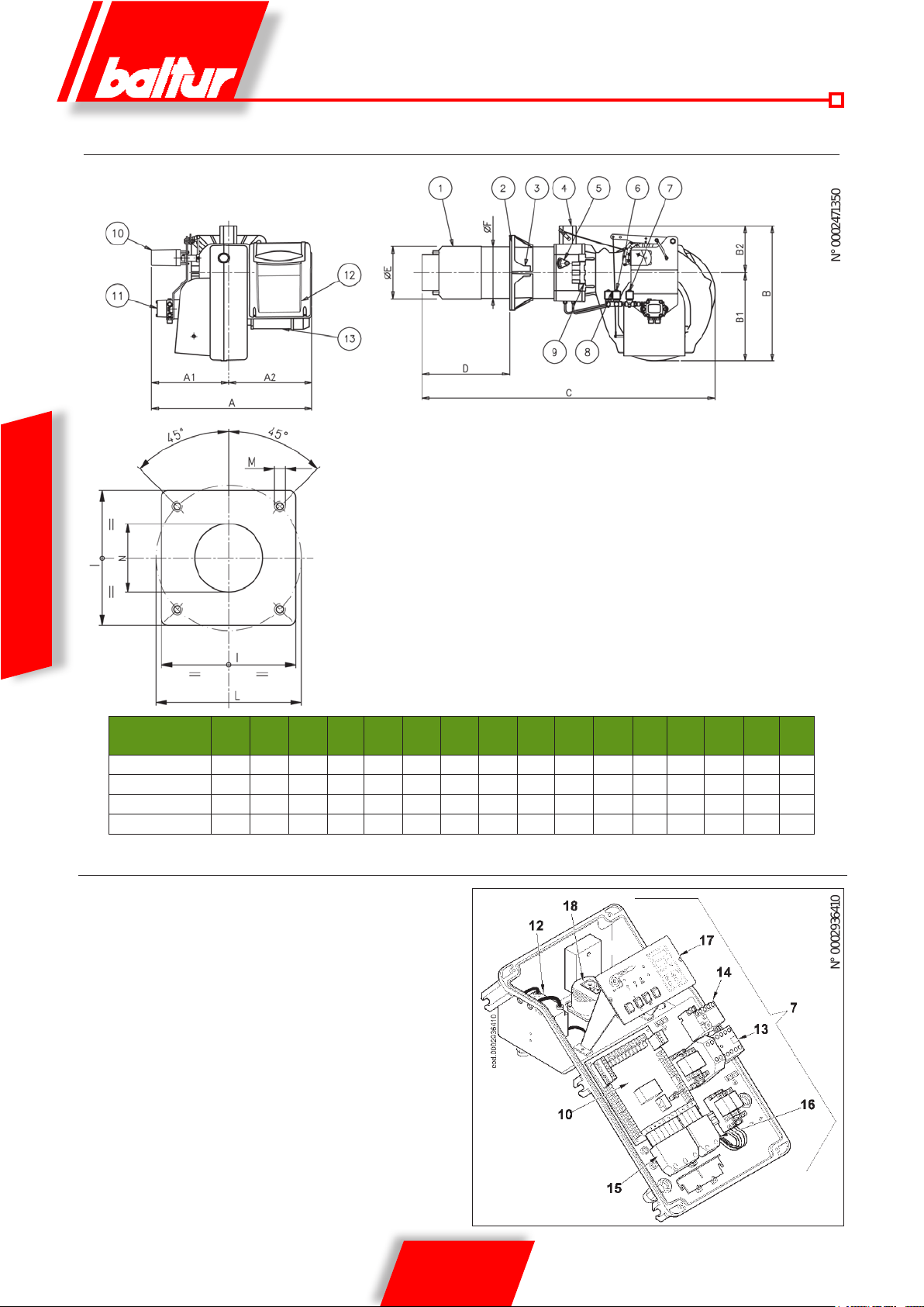
N° 0002936410
N° 0002 47135 0
OVERALL DIMENSIONS
ENGLISH
1) Combustion head
2) Gasket
3) Burner/boiler fixing flange
4) Gas train fixing flange
5) Combustion head adjustment device
nd
6) 2
flame electrovalve
7) Safety electrovalve
st
8) 1
flame electrovalve
9) Hinge
10) Air/gas adjusting servomotor
11) Pump
12) Electrical panel
13) Motor
A A1 A2 B B1 B2 C D
D
mín
máxE ØFØ
I L
mín
L
máx
TBML 80 MC 700 330 370 580 380 200 1230 270 440 180 178 280 250 325 M12 190
TBML 120 MC 700 330 370 580 380 200 1250 285 450 224 219 320 280 370 M12 235
TBML 160 MC 700 330 370 580 380 200 1250 285 450 224 219 320 280 370 M12 235
TBML 200 MC 700 330 370 580 380 200 1270 300 470 250 219 320 300 370 M12 255
ELECTRICAL PANEL COMPONENTS
10) Equipment
12) Ignition transformer
13) Motor contactor
14) Thermal Relay
15) 7 pole plug
16) 4 pole plug
17) Mimic panel
M N
6 / 36
0006081544_201408
Page 45
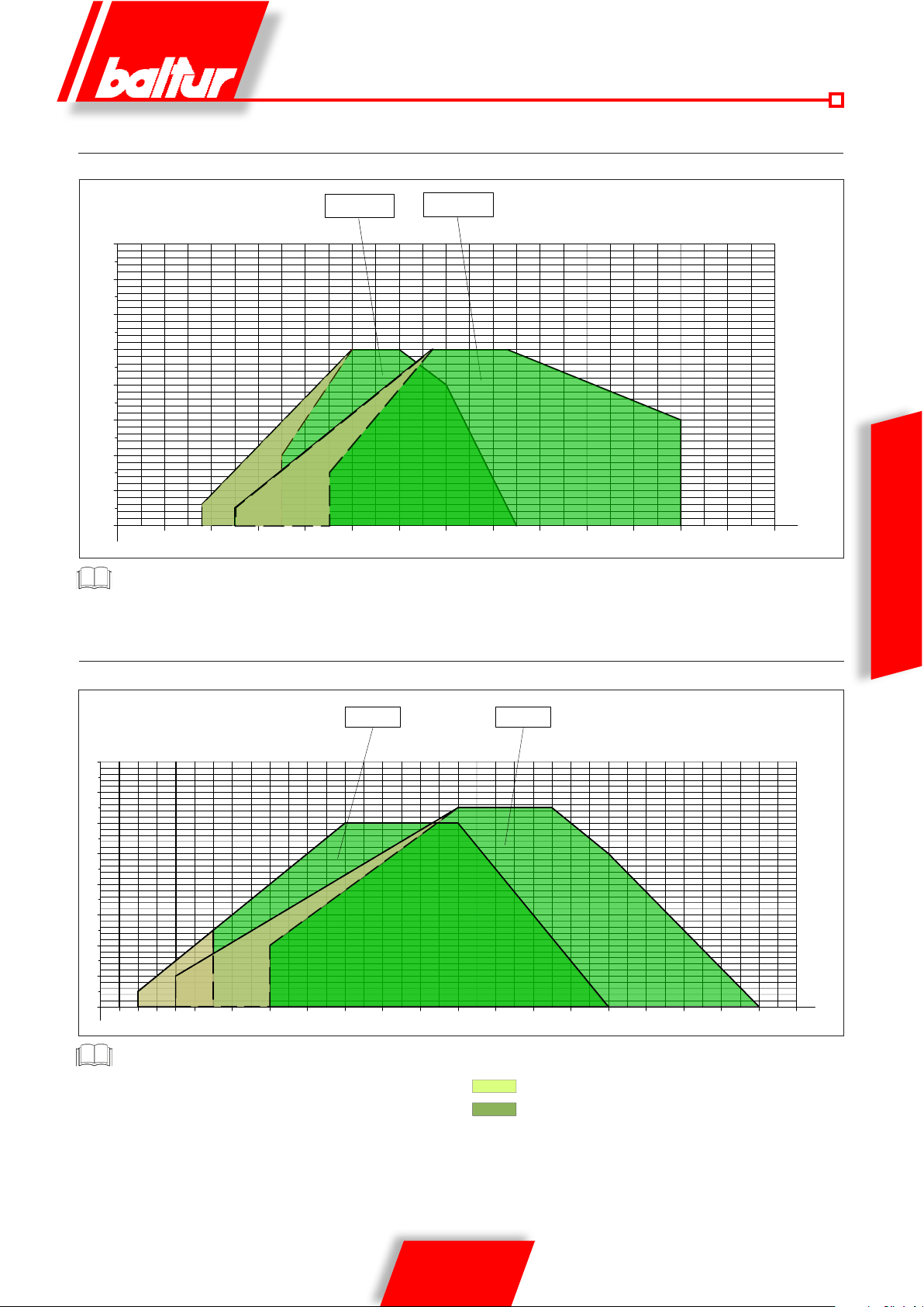
2
4
6
8
0
10
12
14
mbar
0002922743A
100
200 300 400 500 600 700 800 900 1000
kW
15
1100 1200 1300 1400
2
4
6
8
0
10
12
14
mbar
0002922743B
300 400 500 600 700 800 900 1000
kW
15
1100 1200 1300 1400 1500 1600 1700 1800 1900
2000 2100
TBML 80 TBML 120
TBML 160 TBML 200
TBML 80 MC - 120 MC OPERATING RANGE
TBML 80 TBML 120
mbar
15
14
12
10
8
6
4
2
0002922743A
0
100
200 300 400 500 600 700 800 900 1000
Thermic power TBML 80 gpl = 190kW
TBML 160 MC - 200 MC OPERATING RANGE
1100 1200 1300 1400
kW
ENGLISH
Thermic power TBML 200 gpl = 1930kW
The operating ranges are obtained from test boilers corresponding
to Standard EN 267 and are indicative of the c ombinati on bur nerboiler. To ensure c orrect bur ner operation, the dimensions of t he
combustion chamber must c omply wit h current reg ulations; if this
is not the case, consult the manufacturers.
7 / 36
0006081544_201408
Thermal power of methane gas
Thermal power of diesel oil
Page 46
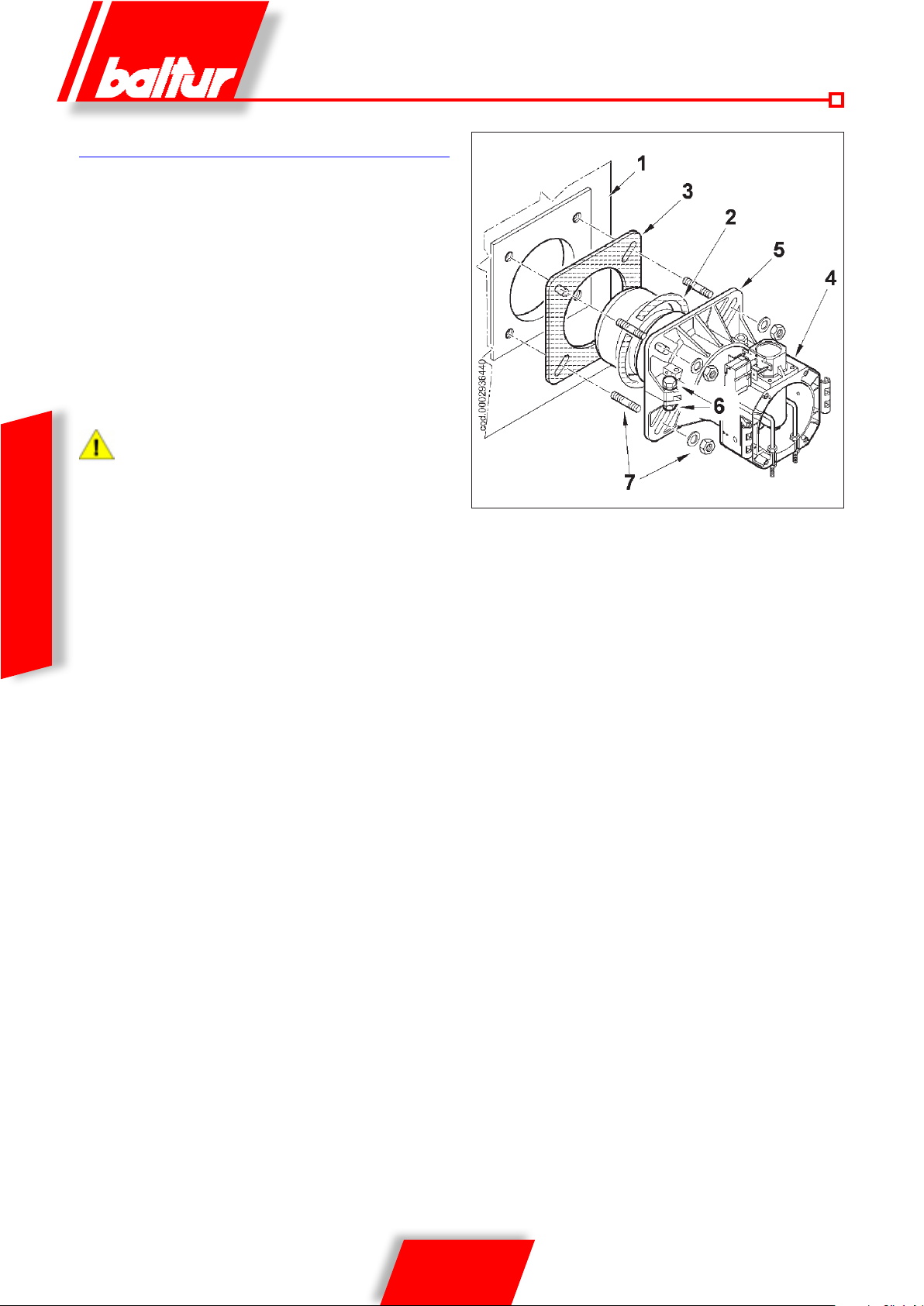
BURNER CONNECTION TO THE BOILER
ASSEMBLING THE HEAD UNIT
• Adjust the position of connector ange 5 by loosening the
screws 6 so that the combustion head penetrates the advised
amount into the combustion chamber as recommended by the
generator’s manufacturer.
• Fit the rigid pipe in the housing provided on the connection ange
and fasten it with the screw. This pipe will be cut ush with the
diffuser (see 0002934670).
• Position insulating seal 3 on the sleeve, placing cord 2 between
the ange and the seal.
• Fasten the Combustion Head unit 4 to the boiler 1 by means of
the stud bolts, washers and the nuts provided 7.
Completely seal the space between the burner sleeve and
the hole in the refractory material inside the boiler door with
suitable material.
ENGLISH
8 / 36
0006081544_201408
Page 47
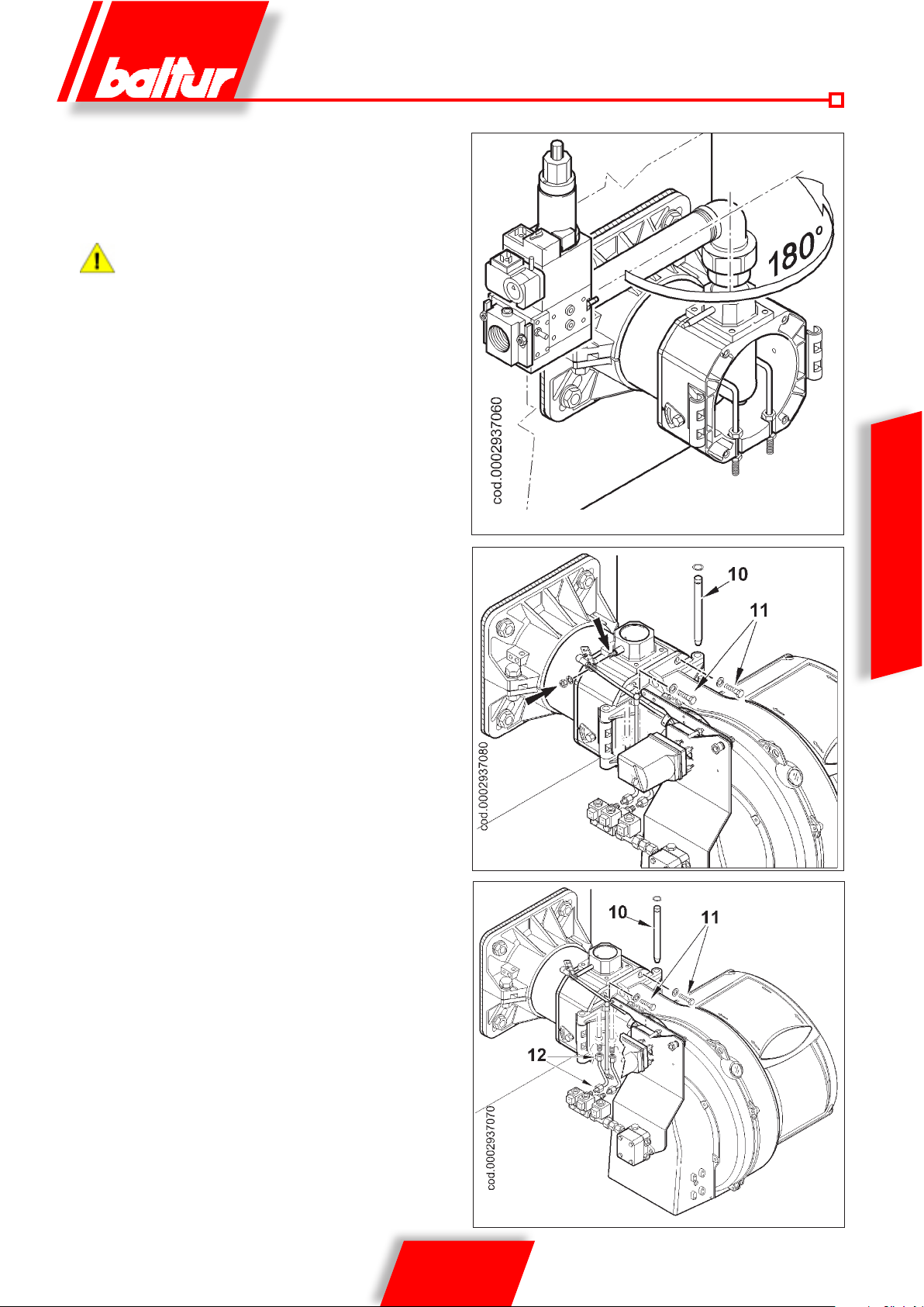
ASSEMBLING THE GAS TRAIN
There are different ways of assembling the
valve train, as shown in drawing 0002936400.
Choose the most rational position for the set-up of the boiler room and the position in which the gas pipeline arrives.
In case of very large valves, e.g. DN65 or DN80, make sure
there is a suitable support to prevent excessive stress on
the gas train fitting.
ASSEMBLING VENTILATING UNIT
• Position the half-hinge on the burner scroll in line with those on
the combustion head assembly.
• Put the hinge pin 10 in the position considered most suitable.
• Connect the cable switch on to the corresponding electrodes,
close the hinge, locking the burner by means of screws 11.
• Insert the gas throttle control lever on the shaft and block it with
the specic nut.
ENGLISH
COMPLETING BURNER SETUP
• Remove the protective (yellow) caps from the couplings placed
beneath the head unit and near the electrovalves.
• Connect the 12 light oil pipes provided with the burner to their
corresponding connectors, making sure they are properly sealed.
9 / 36
0006081544_201408
Page 48
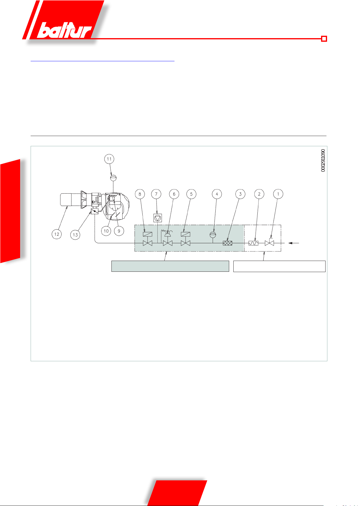
0002911090
GAS SUPPLY LINE
The basic diagram of the gas supply line is shown in the
figure below. The gas train is certified in accordance with EN
676 Standard and is supplied separately from the burner.
A manual shut-off valve and an anti-vibration joint must be
installed upstream of the gas valve, as shown in the diagram.
BASIC DIAGRAM OF THE GAS BURNER
ENGLISH
GAS TRAIN SUPPLIED BY THE MANUFACTURER
1) Manual shut-off valve
2) Anti-vibration joint
3) Gas filter
4) Minimum gas pressure switch
5) Safety valve
6) Pressure regulator
7) Valve seal control device (obligatory for burner with maximum
nominal thermal output over 1200 kW)
RESPONSIBILITY OF THE INSTALLER
8) Slow opening working valve
9) Air/gas adjusting servomotor
10) Air adjustment gate
11) Air pressure switch
12) Combustion head
13) Gas adjustment throttle
10 / 36
0006081544_201408
Page 49
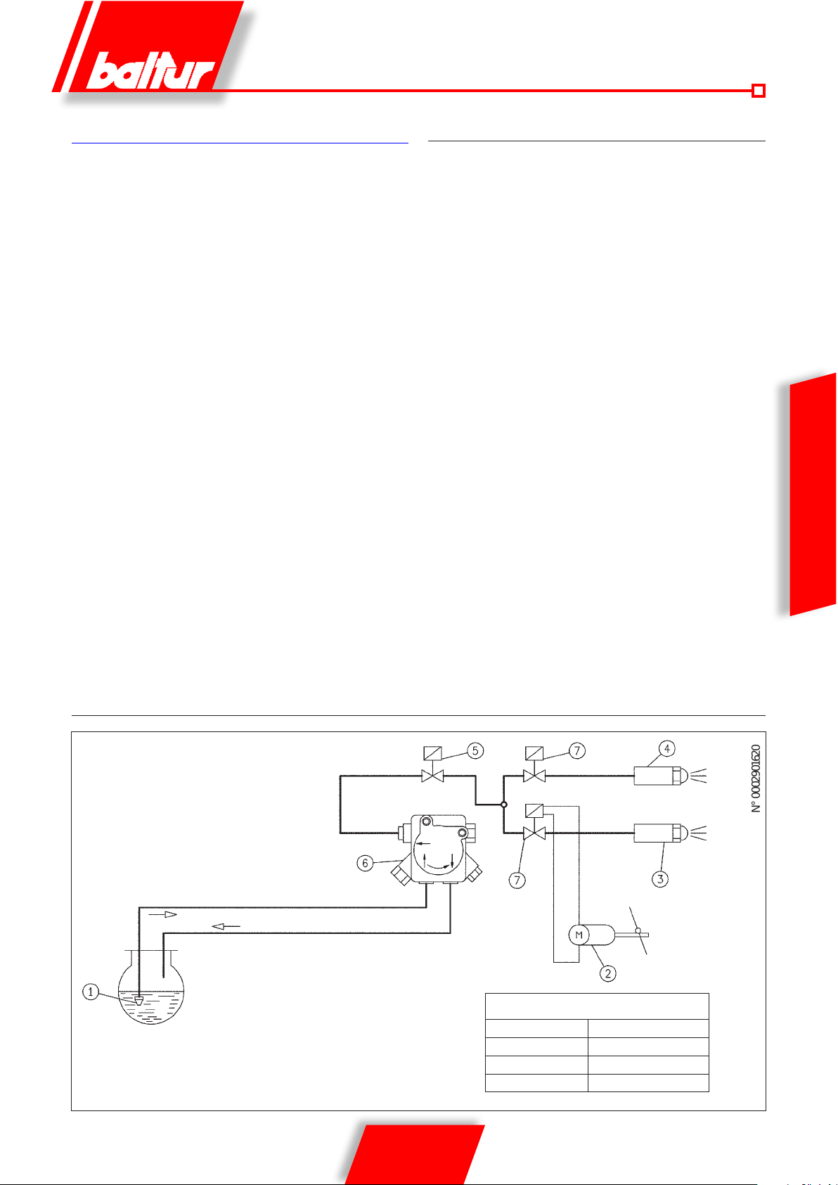
N° 0002901620
DIESEL OIL SUPPLY LINE
The following description covers merely the basic requirements for
an efficient operation.
The unit is equipped with a self-suction pump, capable of sucking oil
directly from the tank also for the first fill-up. This is true as long as
the required conditio ns exist, see p ip e sizin g diagr am s. To ensure
effici e nt op eration, it is preferable to make intake and return pipes
with welded fit tings and to avoid the use of t hreaded c onnect ions
which often cause ai r inf ilt rati ons and dist ur b pump op erat ion an d
consequently burner oper ation. Where a removable coupling is
required, use the welded flan ge method inser ting a fuel resist ant
gasket to obtain a positive sealing. For systems requiring pipes with
a relatively small diameter we recommend the use of copper pipes.
For unavoidable connections we recommend using “biconic” fittings.
The basic diagrams for the dif ferent system types depending on
the position of the tank with respect to the burner are shown below.
The intake pipe should run up -slope towards the bur ner to avoid
the possible build- up of gas bubbles. Where more burners are
installed in one boiler room, it is essential that every burner has its
own suction pipe.
Only return pipes can lead to a single manifold pipe with an adequate
cross section le ading to the tank. Never connect the retur n pipe
directly to the suction pipe.
It is a good practice to properly heat-insulate the suction and return
pipes to prevent hazardous cooling. Pipe diam eters (to be strict ly
complied with) are listed in the following tab les. The maximum
amount of vacuum that the pump can withstand no i s el e ssly under
normal operating conditions is 35 cm.Hg. ; if these limit is exceeded
normal pump operation will no longer be guaranteed.
Maximum suction and return pressure = 1 bar.
AUXILIARY PUMP
In some cases (excessive distance or difference in level) it is
necessary to install a “loop-type” supply system with an auxiliary
pump, thus avoiding the burner pump from being directly connected
to the tank.
In this case, the auxiliary pump can be started with the burner starts
and stopped when it stops.
The electric wiring of the auxiliary pump is made by connecting
the coil (230 V) which controls the pump remote control switch to
terminals 2 (N) and 17 of the printed circuit.
Always follow the instructions below:
• The auxiliary pump should be installed as near as possible to
the liquid to be sucked.
• The head must be suitable for the relative plant.
• We recommend a ow rate equal at least to that of the burner
pump.
• Connection pipes should be sized to cope with the ow rate of
the auxiliary pump.
• Do not connect the auxiliary pump directly to the remote control
switch of the burner motor.
ENGLISH
HYDRAULIC CIRCUIT SCHEMATIC DIAGRAM
SUCTION
RETURN
1 - Foot valve
2 - Air adjustment servomotor
nd
3 - 2
ame nozzle
st
4 - 1
ame nozzle
5 - Safety valve usually closed
6 - Pump (12 bar)
7 - Valve usually closed
Pressure loss in hydraulic circuit
TBML 80 MC 1 bar
TBML 120 MC 1.5 bar
TBML 160 MC 2 bar
TBML 200 MC 2.5 bar
11 / 36
0006081544_201408
Page 50
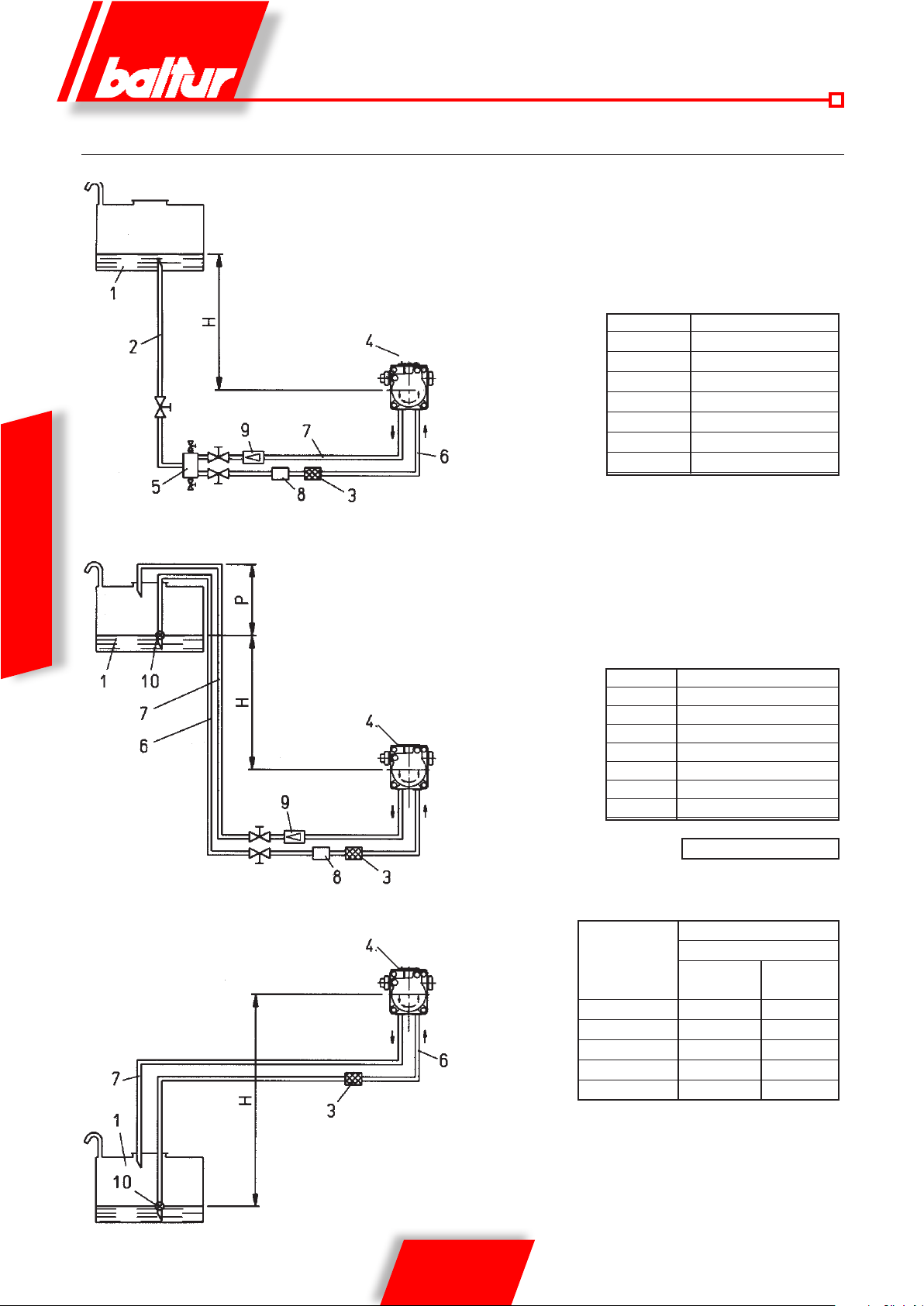
PIPE SIZING DIAGRAMS TBML 80 MC
GRAVITY SUPPLY SYSTEM
ENGLISH
1 Tank
2 Feeding pipe
3 Wire-net lter
4 Pump
5 Degasier
PUMP AXIS
DROP-TYPE SYSTEM WITH SUPPLY FROM THE TANK TOP
1 Tank
3 Wire-net lter
4 Pump
6 Intake pipe
7 Return pipe
6 Suction pipe
7 Burner return pipe
8 Automatic fuel interception
with the burner off
9 Non-return valve
8 Automatic fuel interception device at
9 Non-return valve
10 Foot valve
H Gesamte L.
Meter Meter
Ø i. 14 mm.
1 30
1.5 35
2 35
2.5 40
3 40
burner shut off
1 Tank
3 Wire-net lter
4 Pump
6 Suction pipe
7 Return pipe
10 Foot valve
PUMP AXIS
PUMP AXIS
H Gesamte L.
Meter Meter
Ø i. 14 mm.
1 30
1.5 35
2 35
2.5 40
3 40
Maßzahl T = 3.5 m. (Max.)
INTAKE SUPPLY SYSTEM
Total meters
H
meters
0.5 26 45
1 22 38
1.5 19 31
2 14 25
2.5
: For any components missing in the pipes, comply with current
NOTE
regulations.
H = Difference in level between level in the tank and the pump axis.
L = Maximum length of suction pipe including the vertical lift.
Deduct 0.25 m for each elbow or gate.
meters
Ø i. 14
mm.
11 19
Ø i. 16
mm.
12 / 36
0006081544_201408
Page 51
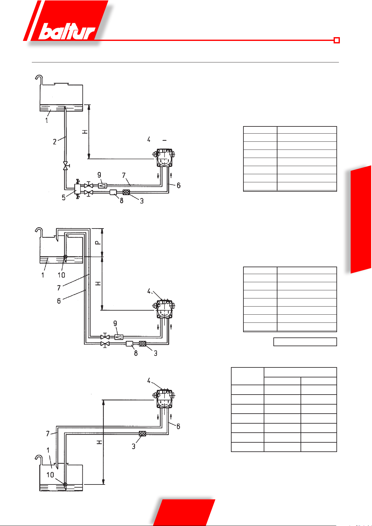
TBML 120 MC - 160 MC - 200 MC PIPE SIZING DIAGRAMS
GRAVITY SUPPLY SYSTEM
1 Tank
2 Feeding pipe
3 Wire-net lter
4 Pump
5 Degasier
PUMP AXIS
DROP-TYPE SYSTEM WITH SUPPLY FROM THE TANK TOP
1 Tank
3 Wire-net lter
4 Pump
6 Suction pipe
7 Return pipe
PUMP AXIS
6 Suction pipe
7 Burner return pipe
8 Automatic interception device
with burner off
9 One-way valve
8 Automatic fuel interception device at
9 Non-return valve
10 Foot valve
H Gesamte L.
Meter Meter
Ø i. 16 mm.
1 40
1.5 45
2 45
2.5 50
3 50
burner shut off
H Gesamte L.
Meter Meter
Ø i. 16 mm.
1 40
1.5 45
2 45
2.5 50
3 50
ENGLISH
1 Tank
3 Wire-net lter
4 Pump
6 Suction pipe
7 Return pipe
10 Foot valve
PUMP AXIS
Maßzahl T = 3.5 m. (max.)
INTAKE SUPPLY SYSTEM
H
meters
0.5 36 55
1 30 48
1.5 25 41
2 20 32
2.5 15 24
3 10 15
3.5 4 7.5
NOTE
: For any components missing in the pipes, comply with current
regulations.
H = Difference in level between level in the tank and the pump axis.
L = Total pipeline length including the vertical length.
Deduct 0.25 m for each elbow or gate.
13 / 36
0006081544_201408
L total metres
Ø i. 14 mm. Ø i. 16 mm.
Page 52
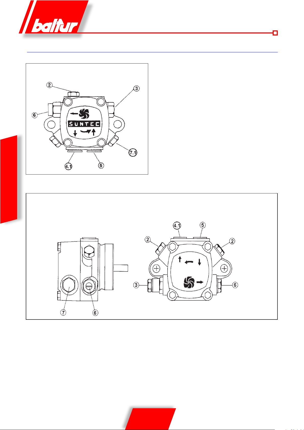
SUNTEC PUMP DETAILS
AJ4 - AJ6
ENGLISH
AN 47 - 57 - 67 - 77 - 97
2 PRESSURE GAUGE CONNECTOR AND AIR VENT (1/8” G)
3 PRESSURE ADJUSTING SCREW
8894-1
3.1. REMOVE THE NUT TO HAVE ACCESS TO THE PRESSURE
ADJUSTING SCREW (AN.. 11-14 BAR, AJ..11-16 BAR)
4 RETURN
4.1 RETURN WITH INNER BY-PASS DOWEL
5 SUCTION
6 DELIVERY
7 VACUUM GAUGE CONNECTOR (1/8” G)
7.1 VACUUM GAUGE CONNECTOR AND INTERNAL BY-PASS
DOWEL
NOTE: The pump is pre-adjusted to a pressure of 12 bar.
0002900331
14 / 36
0006081544_201408
Page 53
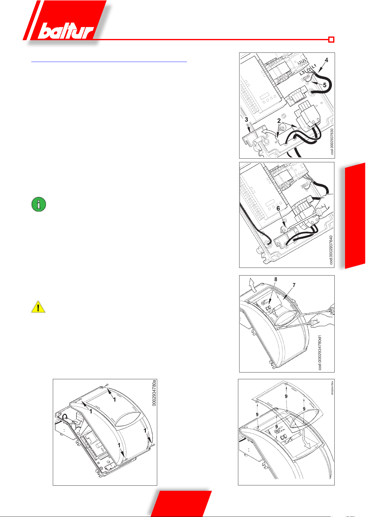
ELECTRICAL CONNECTIONS
The three-phase power supply line must have a switch with fuses. The
regulations further require a switch on the burner’s power supply line,
outside the boiler room and in an easily accessed position. For the
electrical connections (line and thermostats), follow the wiring diagram
enclosed. To carry out the connection of the burner to the power supply
line proceed as follows:
• Remove the lid by unscrewing the 4 screws (1) in gure 1, without
removing the transparent door. In this way the burner’s electrical
panel can be accessed.
• Slacken the screws (2) and, after removing the cable oat (3), pass
the two 7 and 4 pole plugs through the hole (see gure 2). Connect
the power supply cables (4) to the contactor, connect the cable to
ground (5) and close the cable holder.
• Reposition the cable oat as in gure 3. Turn the cam (6) so that
the oat exerts sufcient pressure on the two cables, then tighten
the screws that fasten the cable oat. Finally, connect the two 7
and 4-pole plugs.
the housings of the cables for the 7 and 4-pole plugs are
provided respectively for cable Φ 9.5÷10 mm and Φ 8.5÷9 mm;
this ensures that the protection degree is IP 54 (IEC EN60529
Standard) for the electrical panel.
• T o close the switchboard cover, tighten the 4 screws (1) to a torque
of approx. 5 Nm in order to ensure proper sealing. Now, to gain
access to the control panel (8), release the clear door (7), by slightly
prising with a tool (e.g. screwdriver) in the direction of the arrows
shown in gure 4, let it slide shortly and then separate it from cover.
• T o properly secure the transparent door on the pa nel again, proceed
as indicated in 5: position the hooks at their hooking points and (9)
slide the door in the direction indicated by the arrow until it clicks.
It is now well sealed.
only professionally qualified personnel may open the burner
electrical panel.
Figure 2
ENGLISH
Figure 3
Figure 4
Figure 1 Figure 5
15 / 36
0006081544_201408
Page 54
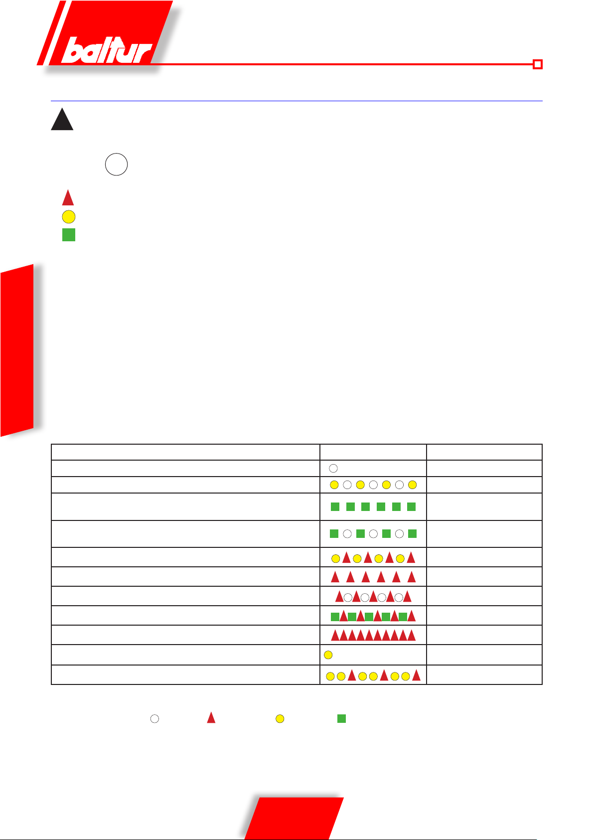
COMMAND AND CONTROL EQUIPMENT FOR GAS BURNERS LME 73...
For more information, consult the machine quick Guide supplied with the manual.
!
Info
↵
RED
YELLOW
GREEN
The lock reset push button (EK) and the multicolour indicator light (LED) are both located on the control panel.
There are two diagnostics options:
1. Visual diagnostics: indication of the operating status or diagnostics of the lock cause
2. Diagnostics: display and operating unit through BCI up to AZL2 ...
1
) visual diagnostics:
during normal operation, the various operating statuses are indicated by colour codes according to the colour table below.
OPERATING STATUS INDICATIONS
ENGLISH
During ignition, the following status indications are provided as per the table below:
Colour code table for the indicator light (LED)
The lock reset push button
activate/deactivate the diagnostics functions.
The multicolour indicator light (LED) is the key element for visual diagnostics.
1
) (info push button) (EK) is the key element to reset the burner control and
Condition / status Colour sequence Colours
Wait time (TW), other intermediate statuses
Ignition phase, controlled ignition
Correct operation, current strength of ame detector above the mini-
mum allowed
Incorrect operation, current strength of ame detector below the mini-
mum allowed
Decrease in power supply voltage
Burner in lock condition
Fault indication (see colour legend)
Extraneous light upon burner start-up
Interface diagnostics
Heat request
New program sheet
Legend
..... Fixed ON Off Red Yellow Green
. . . . . . . . . . . . . . . .
. . . . . . . .. . . . . . . . . .
Alternating Yellow and Red
Alternating Green and Red
OFF
Intermittent yellow
Green
Intermittent green
Red
Intermittent red
Quick ashing red
Yellow
Yellow - yellow - red
16 / 36
0006081544_201408
Page 55

PME7... PROGRAM MODULE FOR LME7...WITH PROGRAM SEQUENCES OIL OR GAS BURNERS FOR
LME7...BASIC UNIT REFER TO BASIC DOCUMENTATION P7105
Type reference PME73.810A2 PME73.820A2 PME73.830A2 PME73.840A2
For operation with LME73.000A... x x x x
Gas program forced draft burner x x x x
1-stage / 2-stage or 1-stage modulating x x x x
Pilot burner intermittent / interrupt --- --- x x
Modulating via actuator (MCeumatically, mechanical gas-air ratio
control
Actuator control via analog signal / 3-position step signal for actuator
with potentiometer
3-position step signal for actuator without potentiometer --- x --- x
Control sequence programmable time x x x x
POC x x x x
Valve proving x x x x
x x x x
x --- x ---
Equipment or
programmer
Safety time
Pre-ventilation
time
Pre-ignition Post-ignition
Time between open-
st
ing of 1
ame valve
nd
and 2
ame valve
Air gate opening
stroke time
LME 73.... 3 30 2 2 11 30 30
DESCRIPTION OF OPERATION
WITH LIQUID FUEL
FURTHER INSTRUCTIONS TO START A MIXED BURNER
It is advisable to perform the first ignition with liquid fuel because in
this case delivery is conditioned by the available nozzle, whereas
the delivery of methane can be varied as you like by adjusting its
flow-rate regulator.
It is not advisable to oversize the burner with respect to the boiler
for heating and hot water production purposes as the burner may
work for long periods with a single ame, making the boiler work at
lower outputs than the required ones; as a result, the combustion
products (fumes) emerge at too low a temperature (at about 180°
C in the case of fuel oil and 130° C with diesel oil), causing soot
to build up at the chimney outlet. Furthermore, when the boiler
operates at a capacity lower than what is indicated in the technical
data, it is very probable that acid condensate and soot will form in
the boiler, causing its rapid clogging and corrosion. When the two-
ame burner is installed on a boiler for the production of hot water
for heating, it must be connected in such a way as to work normally
with both ames completely stopping, without changing to the rst
ame, when the pre-set temperature has been reached. To obtain
this particular operation, do not install the second ame thermostat
and make a direct connection between the terminals of the 4-pole
plug (jumper). In this way, only the burner’s capacity will be used for
ignition at a reduced ow rate for a soft start, which is an essential
condition for boilers with a (pressurized) combustion chamber, but
also very useful for normal boilers (vacuum combustion chamber).
The burner’s command (on or off) is connected to the normal
operating or safety thermostats.
By switching off switch 1, if the thermostats are closed, the
voltage reaches the command and control equipment (switching
on Led 2) which starts it working. The fan motor (LED 3)
and the ignition transformer (LED 4) are then switched on.
The motor turns the fan that carries out an air wash of the combustion
chamber and, at the same time, the fuel pumps that cause circulation
in the ducts expel any gas bubbles through the return valve. This prewash stage ends with the opening of the safety solenoid valves and
the rst ame (LED 5), which allows the fuel at a pressure of 12 bar
to get to the rst ame’s nozzle and from this to enter the combustion
chamber nely atomised. As soon as the atomized fuel exits the
nozzle, it is set on re by the spark present between the electrodes
since the start of the motor. During rst ame ignition, the air gate is
held in the position set on the special air/gas adjustment servomotor
cam. If the ame appears regularly after the safety time foreseen
by the electrical device, it starts the air/gas adjustment servomotor
that moves to the second ame position. During passage from the
rst to the second ame, the servomotor activates the electrovalve
(normally closed) for the second ame (LED 6). The opening of the
Air gate closing
stroke time
ENGLISH
17 / 36
0006081544_201408
Page 56
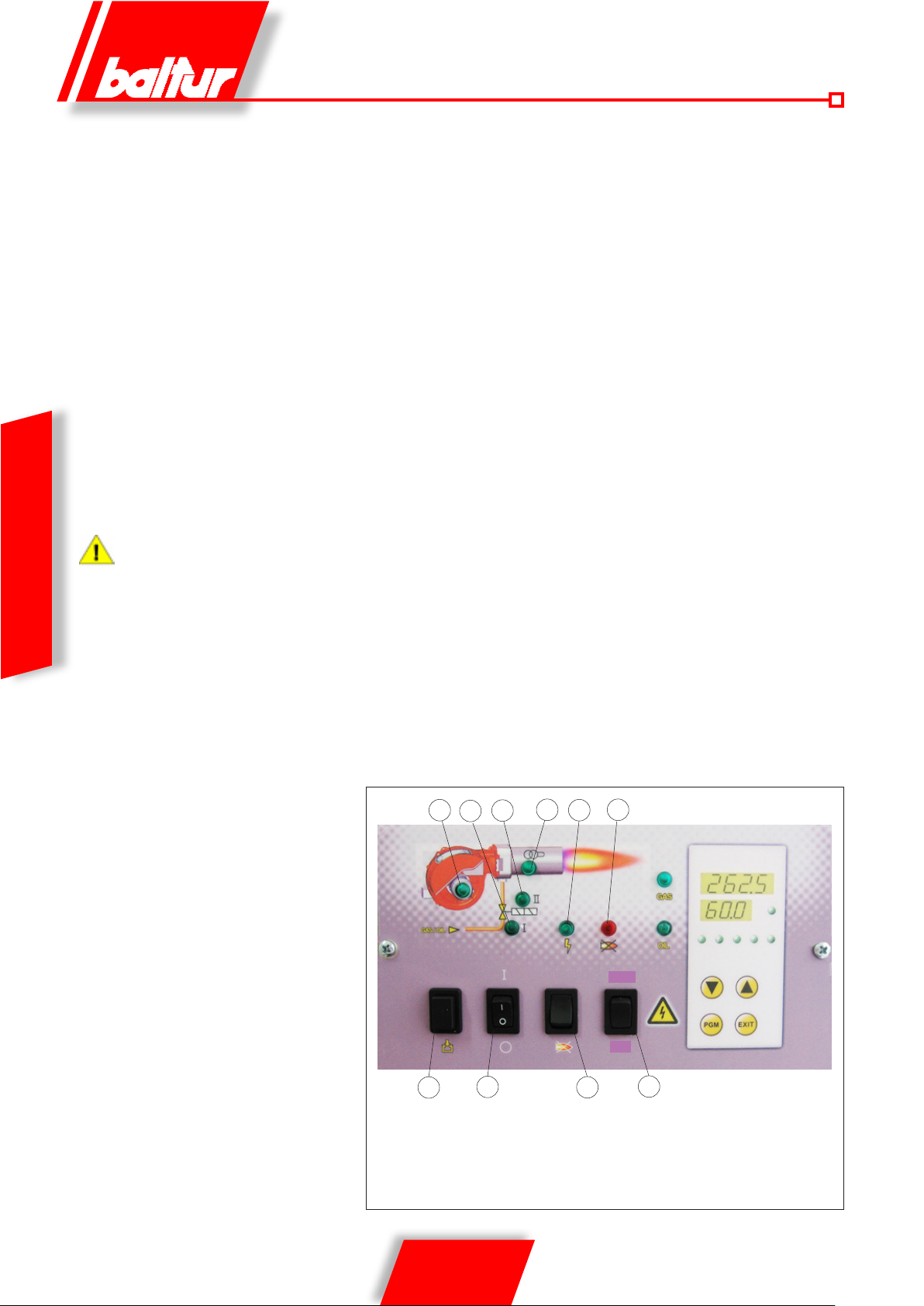
2nd ame valve allows the diesel oil, at a pressure of 12 bar, to
reach the 2nd nozzle and the burner to operate at full capacity. From
the time the ame appears in the combustion chamber, the burner is
controlled by the photoelectric cell and thermostats.
The command equipment continues the program and disconnects
the ignition transformer. When the temperature or pressure in
the boiler reaches the value to which the thermostat or pressure
switch is calibrated, its intervention will cause the burner to stop.
Subsequently, if the temperature of pressure decreases below the
lower thermostat or pressure switch threshold value, the burner will
switch on again. If, for any reason, the ame is lost during burner
operation, after just one second the ame control device cuts off the
power supply from the corresponding relay to automatically switch
off the electrovalves which intercepts the nozzle ow. The switch on
stage is thus repeated and, if the ame ignites again normally, the
burner starts working again normally, if not (if the ame is irregular
or fails to light completely) the equipment goes automatically into
lock-out (LED 7). If the program is interrupted (due to a power supply
failure, manual action or the intervention of the thermostat, etc.)
during the pre-wash stage, the programmer returns to its starting
position and will automatically repeat the whole of the burner ignition
sequence.
The selection of the nozzles in function of the desired total
flow rate (2 nozzles in operation) must be made accounting
ENGLISH
for the flow rate values that correspond to the diesel operating
pressure of 12 bar. It is of course possible to vary within wide
limits the relationship between the first and the second flames
by replacing the nozzles.
6
9
1 Main switch ON - OFF
2 Power LED
3 Fan LED
4 Transformer ON led
5 2nd stage LED
0006081544_201408
1
18 / 36
4
5
7
23
display TBML 80 PN
GAS
OIL
8
10
6 1st stage LED
7 Appliance shutdown LED
8 Appliance unlock button
9 Fuel fill button
10 Fuel switch
Page 57

FIRST FILLING UP OF PIPELINES
After making sure that the protective plastic caps inside the pump
ttings have been removed, proceed as follows:
• Set the burner switch on “O” to prevent an automatic connection
of the burner.
• Make sure, in case of a three-phase burner, that the motor
revolves anti-clockwise when watching it from the pump side.
The rotation direction can be determined also looking at the
direction of fan rotation through the inspection window on the
back of the scroll. To start the motor, close the remote control
switch manually (pressing on the mobile part) for a few seconds
and watch the direction of the rotation of the fan. If it is necessary
to change the rotation direction, reverse the two phases to the
motor contactor terminals K1.
To determine the rotation direction, wait until the fan turns
very slowly, because it is quite easy to misinterpret the
rotation direction.
• Disconnected, if already connected, the exible pipes from both
suction and return lines.
• Dip the end of the suction exible pipe into a vessel containing
either lubrication oil or fuel oil (do not use low viscosity products
such as gas-oil, light oil, kerosene. etc).
• Now press key (9) on the control panel to start the motor and the
pump. Wait until the pump has sucked in an amount of lubricant
equal to 1 or 2 glassfuls, then stop. This operation will prevent
the pump from operating dry and will increase the suction power.
Pump operating at 2800 r.p.m. must not work dry otherwise
they will jam (seizure) within a very short time.
• Now connect the exible pipes to the suction line and open
all the gate valves tted on this line and any other similar fuel
cut-off device.
• Press key 9 again to start the pump, which will suck fuel from
the tank. When fuel is seen coming out of the return pipe (not
yet connected), stop.
If the pipe is long, it may be necessary to bleed the air out
through the cap; if the pump is not fitted with a cap, remove
the pressure gauge connector cap.
• Connect the exible return hose to the pipe and open any gate
valves tted on this pipe. The burner is now ready to start up.
IGNITION AND REGULATION
Before starting up the burner make sure that:
• The right type of fuel has been selected.
• Feeding line connections to thermostats or pressure switches
are made exactly according to electric diagram of the control box.
• There is fuel oil in the tank and water in the boiler.
• All the gate valves tted on the fuel oil suction and return pipes
should be open; the same thing applies to any other fuel cut-off
device.
• Make sure that discharge of combustion products takes place
freely (boiler and chimney gate valves open).
• Make sure that the combustion head penetrates the furnace to
the extent requested by the boiler manufacturer. Make sure the
air shut-off device on the combustion head is in the right position
to ensure a correct combustion; the air passage between disk
and head should be signicantly reduced in case of reduced
fuel delivery. When fuel delivery is high, the air passage should
be consequently increased, see chapter “COMBUSTION HEAD
ADJUSTMENT”.
• The nozzles fitted on the burner must be suitable for the
boiler capacity. If necessary, replace them with suitable ones.
In no case should the quantity of fuel delivered exceed the
maximum amount required by the boiler and the maximum
amount allowed for the burner.
To start the burner proceed as follows:
The burners have a switch to pass manually from the 1st to
the 2nd stage.
• To prevent ignition of the second ame, turn the 1st and 2nd stage
switch on the printed circuit to the 1st stage position.
• Adjust the air in the amount presumed to be necessary for the
1st stage ignition using the special cam of the air adjustment
servomotor.
• Set the air adjustment device on the combustion head in
an intermediate position (see “AIR ADJUSTMENT ON THE
COMBUSTION HEAD”).
• Activate the main switch and the control panel switch.
• The programmer starts to operate and activates the burner
devices according to the pre-set program. The burner will start
operation as described in the Chapter “DESCRIPTION OF
OPERATION”.
• When the burner is operating in the 1st stage, adjust the amount
of air necessary to ensure an efcient combustion, see “AIR
ADJUSTMENT ON THE BURNER HEAD” and 000293 for 1st
ame diesel oil adjustment cam.
• After adjusting the air for the 1st stage, stop the burner by cutting
off the current from main switch. Activate the electr ical circuit that
controls the activation of the second ame by turning the 1
2nd stage switch on the printed circuit to the 2nd stage position
• Adjust the air in the amount presumed necessary for
the maximum capacity (2nd stage) using the
screw(s) corresponding to the bearing (13).
- in a clockwise direction the air ow increases,
- in an anti-clockwise direction the air ow decreases.
• Now connect the burner again; it will start and automatically
switch to the 2nd stage according to the pre-set program.
st
and
ENGLISH
19 / 36
0006081544_201408
Page 58
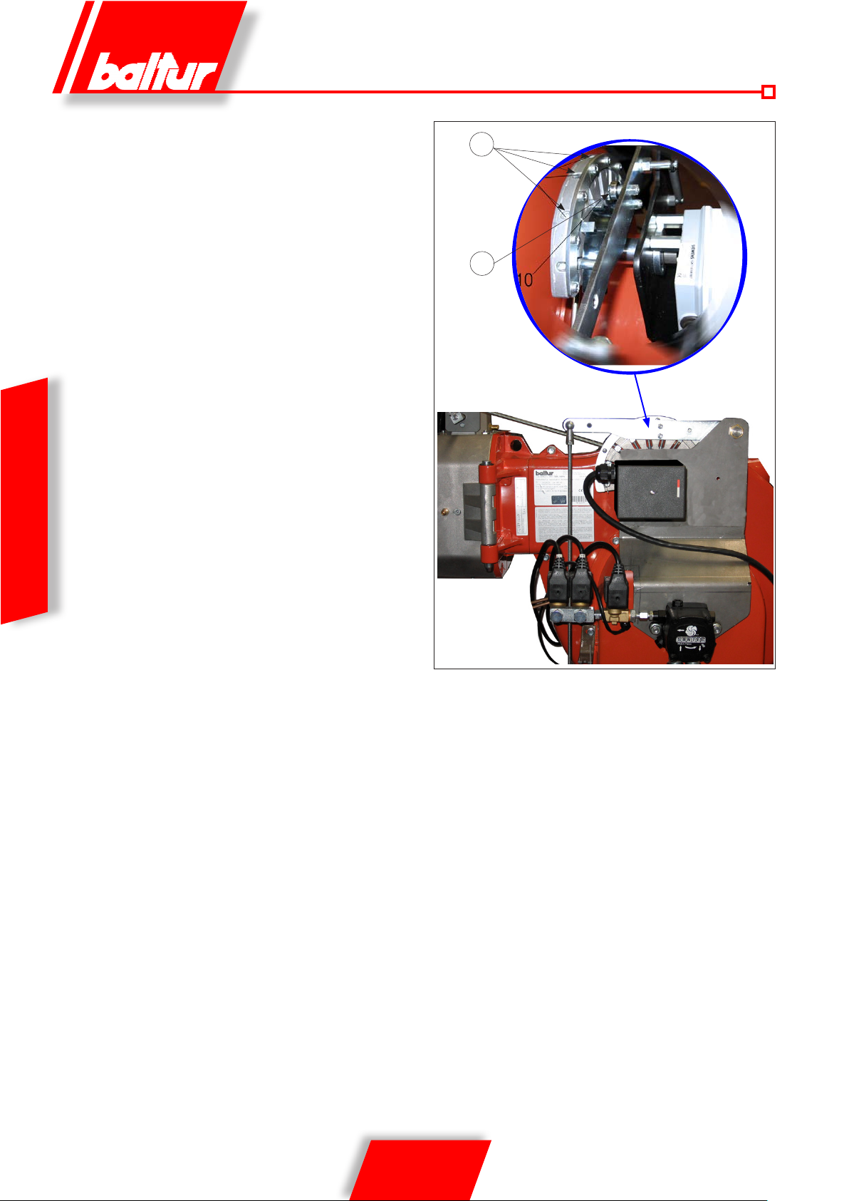
• With the equipment operating in the 2nd stage, adjust the
amount of air necessary to ensure efficient combustion.
Check combustion with the special instruments. If suitable
instruments are not available, look at the flame colour.
We recommend that the adjustment is performed so
as to obtain a soft light orange flame; avoid red flames
with smoke and white flames with an excess of air.
Make the regulation so as to obtain a certain amount of carbon
dioxide (CO2) in the smoke, varying from min. 10% to max.
13% with a smoke number not exceeding 2 (Bacharach scale)
12
acc_reg001.psd
13
TBML 80MC 003.psd
ENGLISH
20 / 36
0006081544_201408
Page 59
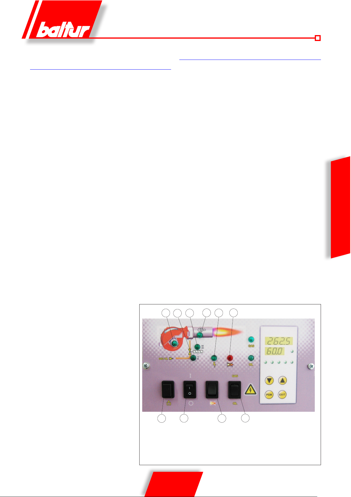
OPERATION DESCRIPTION
WITH GASEOUS FUEL
After activating switch 1, if the thermostats are closed, the voltage
reaches the command and control equipment (LED 2 switches on)
which starts operating. The fan motor is thus switched on (LED 3)
to carry out preventilation of the combustion chamber, at the same
time the air gate control servomotor moves to the opening position
corresponding to the maximum power setting.
At the end of the preventilation stage the air
gate goes back to the ignition ame position.
If the ventilation air control pressure switch has found that there is
sufcient pressure, the ignition transformer will start (LED 4) and,
two seconds later, the safety and main gas valves will open (LED
5).
In particular:
• The main valve is single-stage and slow opening.
• The safety valve is an ON/OFF valve.
• The air gate is activated by an electric servomotor. Remember
that when the thermostat stops the burner, the gate is returned
by the servomotor to the closed position.
The ame is detected by the ame control device and allows the
equipment to proceed to the ignition stage with the switching off of
the ignition transformer. Then the servomotor opens the air gate
gradually and the gas throttle up to the maximum set value.
If there is no ame, the appliance shuts down in “safety lock-out”
mode (LED 7) within 3 seconds of the opening of the main valve.
In safety lock-out mode the valves are closed again immediately.
To release the equipment from this safety position, press button 8
on the synoptic panel.
MODULATION OPERATION DESCRIPTION
When the burner is ignited at the minimum ow-rate, if the modulation probe allows it (adjusted to a temperature or pressure which is
greater than that present in the boiler) the air adjustment servomotor begins to operate;
- in a clockwise direction the air flow increases,
- in an anti-clockwise direction the air flow decreases.
causing a gradual increase in the combustion air ow and con-
sequently of the gas, until it reaches the maximum ow setting of
the burner. The burner remains in the maximum ow position until
the temperature or pressure is high enough to trip the modulation
probe, which reverses the rotation of the air adjustment servomotor.
Reverse rotation of the servomotor and consequently a reduction in
gas and air ow take place in short time intervals. By this method,
the modulation system tries to bring the amount of heat supplied
to the boiler in line with the heat that the boiler puts out to service.
The modulation probe installed on the boiler measures any request
variation and automatically adjusts fuel and combustion air supply, by starting the air/gas adjustment servomotor and increasing
or reducing rotation as necessary. If the limit value (temperature
or pressure) at which the stop device is set (thermostat or pressure switch) is reached even with gas supply at minimum level, the
burner is shut down by the device.
When temperature or pressure returns below the shut-down device
tripping value, the burner is activated once again according to the
program described in the previous section.
ENGLISH
4
6
9
1 Main switch ON - OFF
2 Power LED
3 Fan LED
4 Transformer ON led
5 2nd stage LED
0006081544_201408
1
21 / 36
5
7
23
Display TBML 80 PN
GAS
ÖL
8
10
6 1st stage LED
7 Appliance shutdown LED
8 Appliance unlock button
9 Fuel fill button
10 Fuel switch
Page 60
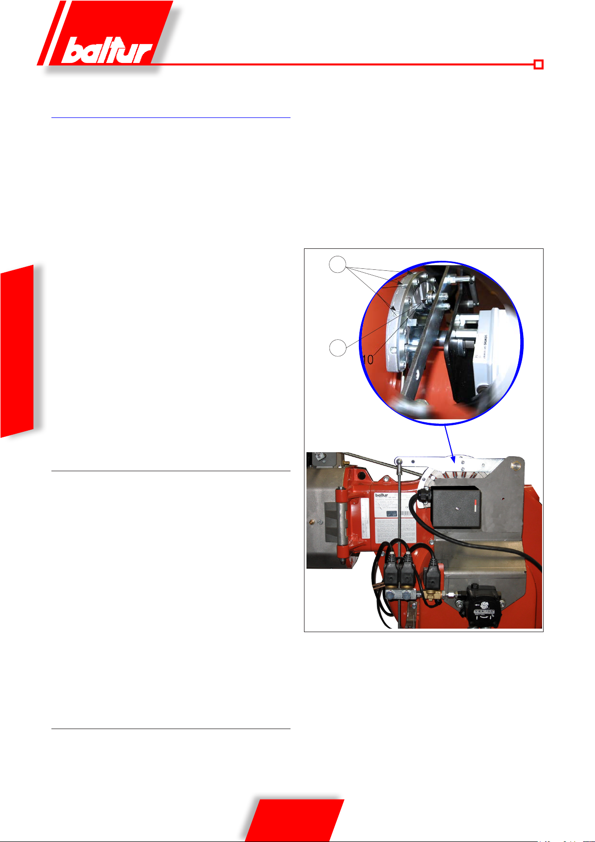
IGNITION AND ADJUSTMENT
WITH METHANE GAS
Adjusting power upon first start-up
• position the rst ame gas ow adjustment cam on the electric
servomotor to an opening angle approximately between 15° and
20° (000293). If it exists, open the safety valve ow regulator
completely.
• Now switch on the switch (1). The command equipment
thus receives voltage and the programmer causes the
burner to switch on as described in chapter “OPERATION
DESCRIPTION”. During preventilation, make sure that the air
pressure control switch changes its status (from the closed
position without pressure measurement to the closed position
with pressure measurement). If the air pressure switch does
not detect sufcient pressure, the ignition transformer (4) is not
switched on, nor are the gas valves (5) and so the equipment
is stopped in “lock-out” (7) mode.
• On rst switching on repeated “lock outs” may occur due to the
following reasons:
- The gas piping has not been vented correctly and so there is
not enough gas to provide a stable ame.
ENGLISH
- The “lock out” with ame present may be caused by ame
instability, due to an incorrect air/gas ratio.
- Correct the air flow in first stage using the screw(s)
(12), corresponding to the bearing (13).
- in a clockwise direction the air ow increases,
- in an anti-clockwise direction the air ow decreases.
stage position without varying the adjustment of the gas valve already
performed in point 5a.
- Adjust the gas ow in the 1st stage to the desired value using
the electric servomotor.
- If necessary, correct the combustion air supply adjusting the
screw(s) (12) as described previously.
- Check the combustion parameters in the 1st stage with
appropriate instruments (C02 max= 10%, O2 min=3%, CO
max=0,1%).
• The air pressure switch prevents the opening of the gas valves
if the air pressure is not the foreseen one. The pressure switch
must therefore be adjusted to intervene closing the c ontact
12
acc_reg001.psd
13
ADJUSTMENT OF SECOND STAGE POWER.
• After rst ignition adjustment, switch off the burner and activate
the electric circuit that controls the activation of the second stage.
Set the switch on the printed circuit to the 2nd stage position.
Ensure that the gas ow adjustment cam in the second
stage of the electric servomotor is positioned at 130°.
- Switch the burner on again activating the main switch (1) on
the synoptic panel. The burner will switch on automatically
and activate the second stage. With the aid of appropriate
instruments adjust air and gas flow according to the
procedures described below:
- Adjust the gas ow using the valve pressure regulator, until
you obtain optimal combustion values, without modifying the
initial air setting for diesel oil. Consult the instructions related
to the single stage gas valve model installed. Avoid keeping
the burner running if the heating capacity is greater than the
maximum amount allowed for the boiler, to avoid damaging it.
- Check the combustion parameters with appropriate
instruments (C02 max= 10%, O2 min=3%, CO max=0,1%)
ADJUSTMENT OF FIRST STAGE POWER.
After having adjusted the burner in the second stage, put the burner
into the first stage. Set the switch on the printed circuit to the 1st
when the air pressure in the bur ner reaches a sufficient
value. If the air pressure switch does not detec t pressure
greater than that calibrated, the equipment r uns through its
cycle but does not switch on the ig nition transformer and
does not open the gas valves and so the burne r “locks-out ”.
To ensure correct operation of the air pressure sw itch you
must, with burner on and in 1
until it is triggered and imme diately “locks-out” the bur ner.
Release the burner by pushing the approp riate but ton (8) and
readjust the pressure switch to a sufcient value to detect the
existing air pressure during the preventilation phase of t he 1st
st
stage, increase its adjustment
TBML 80MC 003.psd
22 / 36
0006081544_201408
Page 61

stage.
• The gas control pressure switch (minimum) prevents burner
operation when gas pressure is not the foreseen one. The
minimum pressure switch must make use of the contact which
is closed when the pres sure switch detec ts a pres sure higher
than its own setting. Therefore the adjustment of the minimum
pressure switch must be carried out when the burner is started
up, in accordance with the pr essure t hat is found f rom ti me to
time. The triggering (opening of the circuit) of any of the pressure
switches when the burner is running (ame on) causes the
burner to stop immediately. When rst switching on the burner
it is essential to check that it works properly.
Once the adjusting operations are completed, visually check
that the thin plate on which the bearing acts has a progressive
profile. Using the special instruments check also that in the
passage from the 1st to the 2nd stage combustion parameters
do not move too much away from the optimal values.
UV PHOTOCELL
Even the slightest greasiness will compromise the passage of the
ultraviolet rays through the UV photocell bulb, thus preventing the
sensitive internal element from receiving the quantity of radiation
necessary for it to work properly. If the bulb is fouled with diesel fuel,
fuel oil, etc., it must be properly cleaned.
Even by simply touching the bulb with fingers, it is possible
to leave a slight greasiness which could compromise UV
photocell operation.
proceed as follows:
- Start the burner.
- After at least one minute, remove the ame detector from its
housing and simulate ame failure. (use a rag to close the
specic opening on the ame detector). The burner ame
should go to out. The burner goes into lock-out within the
time pre-set by the program. The equipment can be reset
only manually by pressing the specic button.
• 3) To check thermostat efficiency, make the burner work
until the water inside the boiler reaches a temperature
of at least 50°C. Then, use the thermostat control
knob to reduce the temperature until you perceive an
opening click and the burner stopping at the same time.
The thermostat tripping should occur with a deviation of 5 ÷ 10
°C with respect to the control thermometer (boiler thermometer).
Alternatively, change the setting of the thermostat scale making
it correspond to that of the thermometer.
ENGLISH
The UV cell does not detect daylight or the light from a common
lamp. Sensitivity can be checked with a flame (cigarette lighter,
candle) or with the electric discharge between the electrodes of a
common ignition transformer.
To ensure proper operation, the UV cell current value should be
sufficiently stable and should not drop below the minimum value
required by the specific equipment; this value is indicated in the
wiring diagram. It may be necessary to search for the best position
by sliding (axial or rotational movement) the casing that contains the
photocell with respect to the fastening clamp. This can be checked
by connecting a micro-ammeter, with a suitable scale, in series to
one of the two UV photocell connection cables. Obviously the polarity
(+ and -) must be respected.
LME 73... equipment needs a cell current between 200 and 500
microA.
CHECKS
• After starting up the burner, check the safety devices (ame
detector, lock-out system, thermostats).
• The ame control device should trip if the ame extinguishes
during operation (this check should be made after at least 1
minute after ignition).
• The burner should be capable of blocking itself and remain
so when a normal ame does not come on during start-up
cycle and within the pre-set on control box. The lock-out
causes the immediate stop of the motor and burner and the
switching on of the corresponding lock-out light indication.
To check the efciency of the ame detector and lock-out system,
23 / 36
0006081544_201408
Page 62
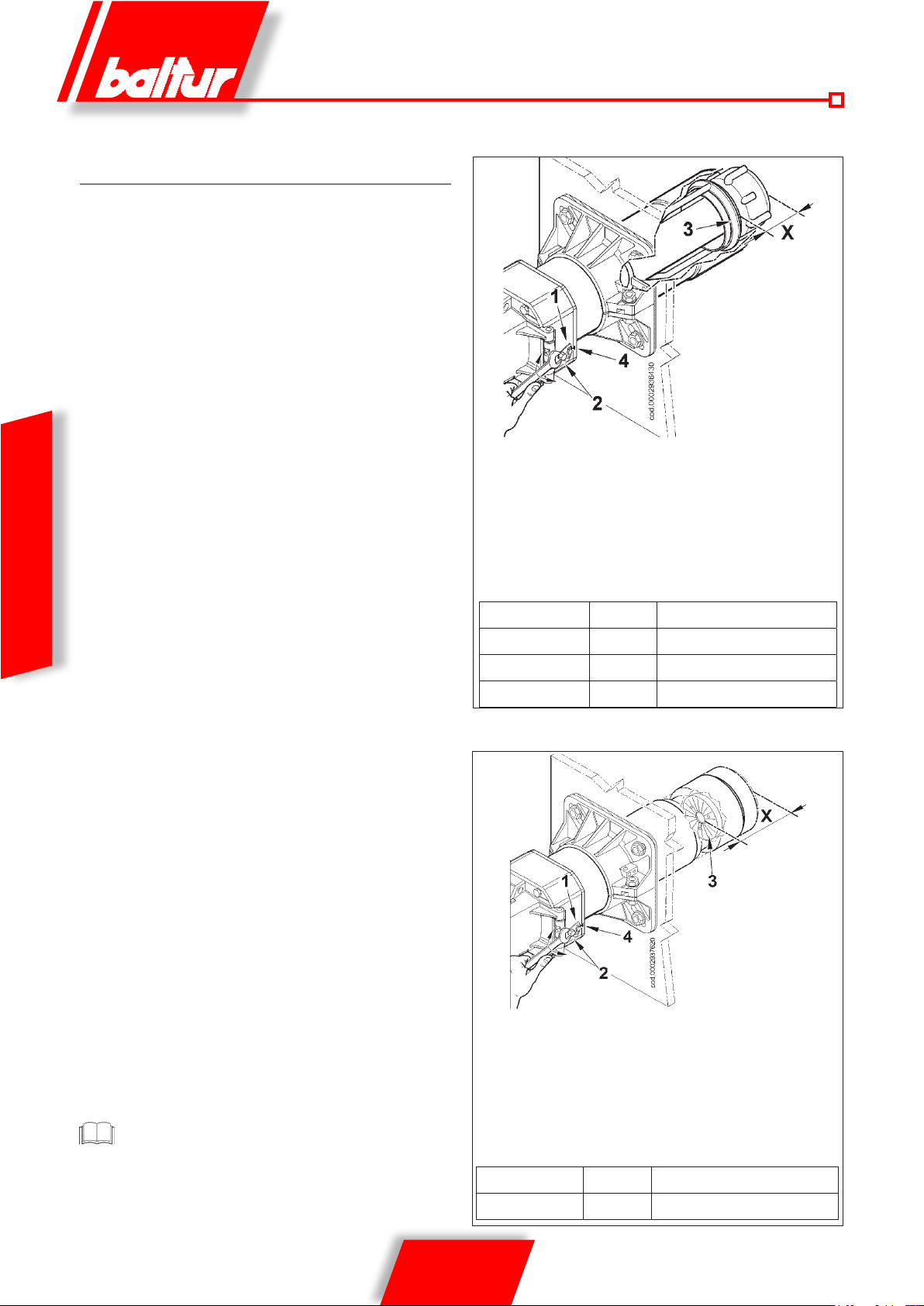
AIR REGULATION ON THE
COMBUSTION HEAD
The combustion head has an adjustment device so that the air
passage between the disk and the combustion head is opened
or closed. You are thus able to obtain, closing the passage, high
pressure upstream of the disk even at low capacity. The high speed
and turbulence of the air provides for its greater penetration into the
fuel and therefore an excellent mixture and flame stability. It can
be indispensable to have high air pressure upstream of the disc to
prevent flame pulsations. This condition is practically indispensable
when the burner works with a furnace that is pressurized and/or has
a high heat load.
It is clear from the above that the device that closes the air to the
combustion head must be set at a position such as to always obtain
very high air pressure behind the disk It is advisable to adjust it in
such a way as to obtain a closure of the air at the combustion head
that will require a significant opening of the air shutter that regulates
the aspiration flow from the burner fan. It is recommended to provide
an air closure on the head that requires a noticeable opening of
the air lock that regulates the burner fan intake flow. Obviously this
condition must occur when the burner operates at the maximum
required output. In practice, start by adjusting the device that closes
the air on the combustion head to an intermediate position, turning
ENGLISH
on the burner for a preliminary adjustment as described above.
When the required maximum supply has been reached, the
position of the device that closes the air at the combustion head
has to be corrected, moving it forward and backwards, in order
to obtain an air flow suitable for the supply with the air shutter
considerably open.
TBML 80 MC ÷ 160MC HEAD REGULATION DIAGRAM
X= Head-disc distance; adjust distance X following the below
instructions:
• loosen screw 1
• turn screw 2 to position the combustion head 3, referring to
index 4.
adjust distance X between the minimum and maximum value
according to what is indicated in the table..
X Value indicated by index 4
TBML 80 MC 87 ÷ 95 1 ÷ 1.5
TBML 120 MC 119 ÷ 155 1 ÷ 5
TBML 160 MC 119 ÷ 155 1 ÷ 5
The above presented adjustments are approximate; position
the combustion head in function of the furnace specifications.
24 / 36
0006081544_201408
X= Head-disc distance; adjust distance X following the below
instructions:
• loosen screw 1
• turn screw 2 to position the combustion head 3 in reference to
index 4.
• adjust distance X between the minimum and maximum value
according to what is indicated in the table.
X Value indicated by index 4
TBML 200 MC 110 ÷ 150 4 ÷ 1
Page 63
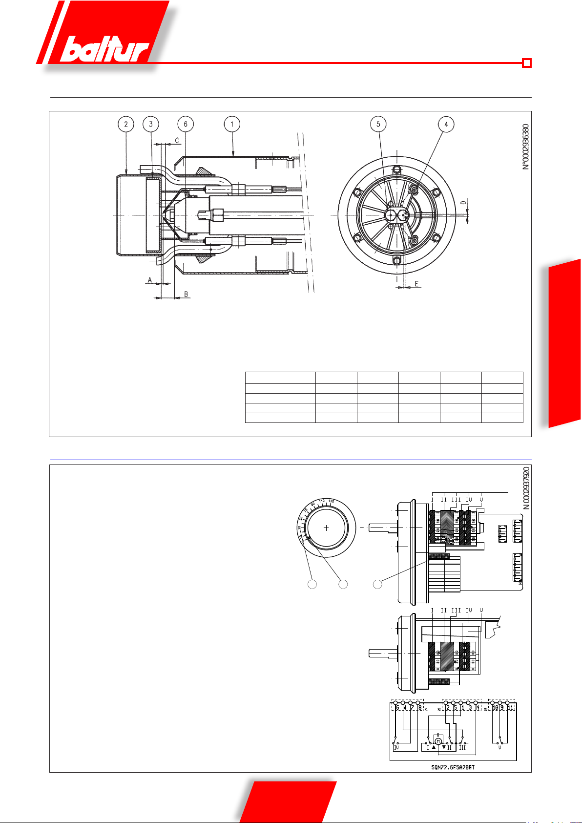
N°0002936380
N 0002937920
ELECTRODE / IONISATION PROBE ADJUSTMENT DIAGRAM
After installing the nozzles, check the correct position of the electrodes and disk
according to the following measurements indicated in mm.
1- Diffuser
2- Internal diffuser
3- Flame disk
4 - Ignition electrodes
5- Nozzles
6- Nozzle holder
It’s advisable to check levels after every intervention on head.
RECOMMENDED NOZZLES: STEINEN type SS 45° (TBML 80 MC - 120 MC - 200MC)
MONARCH type HV 45° (TBML 160 MC)
TBML 80 MC 1 ÷ 1,5 20 ÷ 21 6 ÷ 7 3 ÷ 4 5 ÷ 6
TBML 120 MC 1 ÷ 1,5 20 ÷ 21 6 ÷ 7 3 ÷ 4 8 ÷ 9
TBML 160 MC 1 ÷ 1,5 20 ÷ 21 6 ÷ 7 3 ÷ 4 8 ÷ 9
TBML 200 MC 1 ÷ 1,5 20 ÷ 21 7 ÷ 8 3 ÷ 4 8 ÷ 9
A B C D E
ENGLISH
FUEL/AIR REGULATION SERVOMOTOR
SERVOMOTOR SQN72.6E5A20BT CAM REGULATION
1 Camshaft-motor coupling insertion
and exclusion pin.
2 Reference scale
3- Position indicator
2
Maximum air opening regulation cam (130°)
I
II Total air closure (burner stopped)( 0°)
III Air opening regulation cam for minimum gas (30°)
IV 1st diesel ame air regulation cam (50°)
V Diesel 2nd ame valve activation cam (grater than cam IV) (80°)
Use the corresponding rings to modify the adjustment of the utilized cams
(I - II - III....). The ring pointer indicates the rotation angle set for each cam on
the respective reference scale.
CAM REGULATION
1
3
25 / 36
0006081544_201408
Page 64
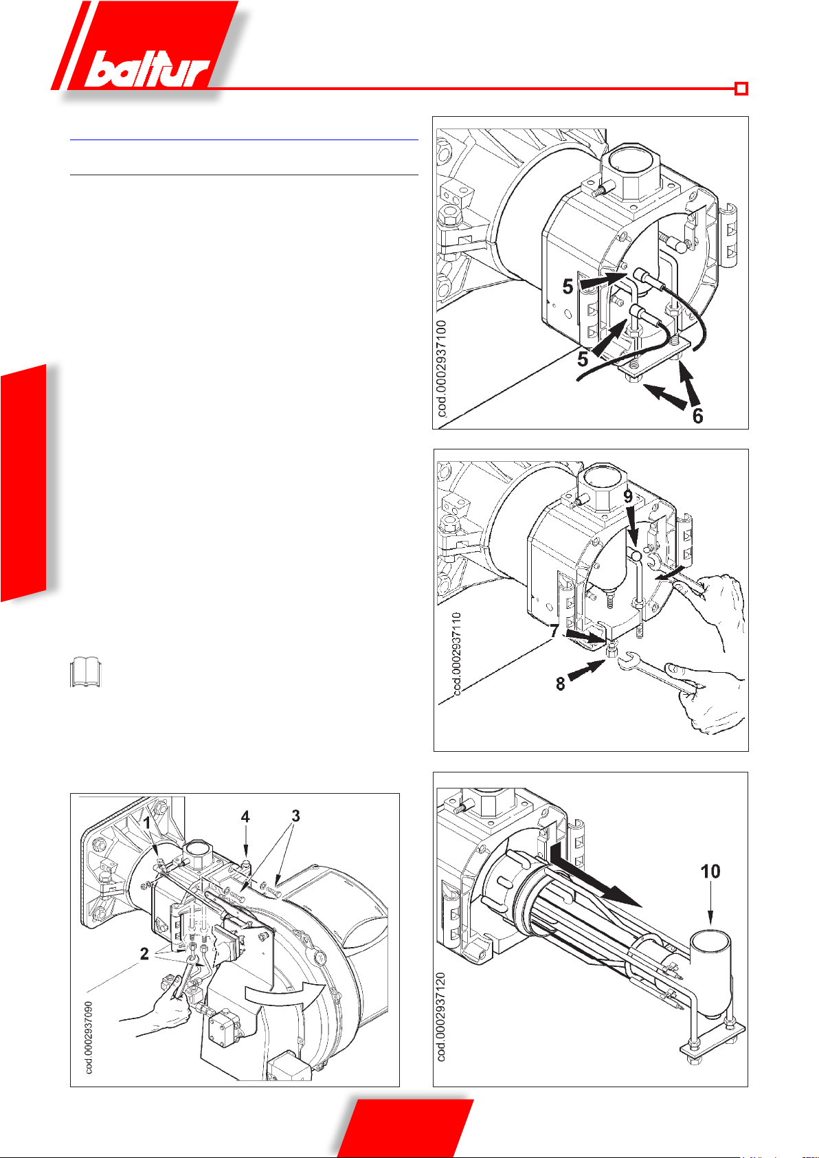
MAINTENANCE
TBML 80 MC
Analyse combustion gases and check that the emission values are
correct at least once a year, in compliance with current law.
• Check the fuel lter: if it is dirty, replace it.
• Check that all the components of the combustion head are in a good
state, not deformed by the temperature and free from impurities or
deposits from the installation environment or by poor combustion
and check also the electrodes are working efciently.
• If the combustion head needs to be cleaned, remove the components
following the procedure indicated below:
- Remove the holding nut and unhook the gas throttle control
lever (1).
- Disconnect the diesel oil hoses (2) from the connectors beneath
the Head Unit (be careful of drips).
- Unscrew the two screws (No.3) and turn the burner around the
pin 4 in the hinge.
- After pulling the ignition cables (5) out of their electrodes, unscrew the locking nuts (6) from the mixing unit. Loosen nut (7)
and completely unscrew the fastening screw on the delivery
connection (8). With the same wrench turn the ball joint (9) in the
ENGLISH
direction indicated by the arrow, unhooking the lever that moves
the combustion head forward.
- Slightly lower the gas delivery connection (10) and remove the
entire mixing unit in the direction indicated by the arrow in gure 4.
- Complete the maintenance work: reassemble the combustion
head, following the operations described above in reverse order,
after having checked the correct position of ignition electrodes
(see 0002936380).
When closing the burner, gently pull the two ignition cables
towards the electrical panel, putting them slightly in tension,
then arrange them in their housing on the scroll. This will ensure
that the two cables do not get damaged by the fan during burner
operation.
figure-2
figure-3
gure 1
26 / 36
0006081544_201408
figure-4
Page 65
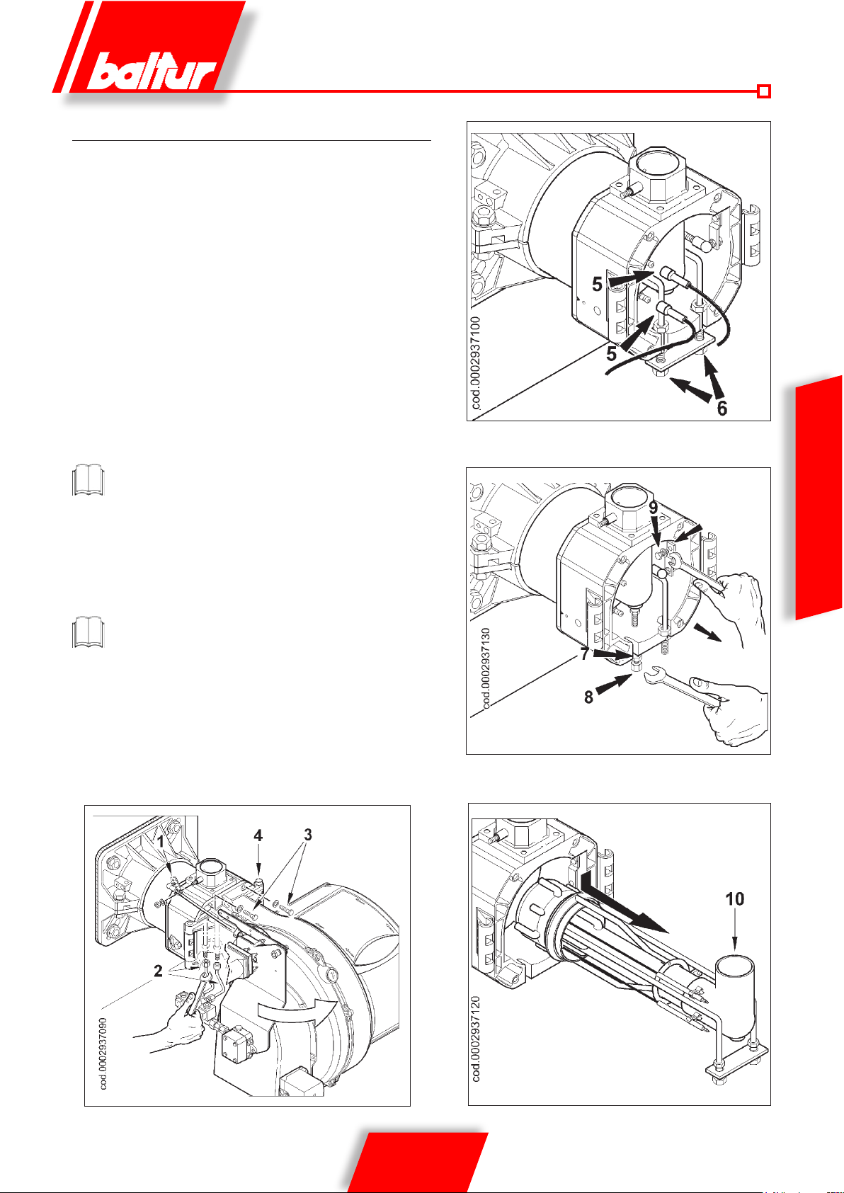
TBML 120 / 160 / 200 MC
Analyse combustion gases and check that the emission values are
correct at least once a year, in compliance with current law.
Check that all components of the combustion head are in good condition,
have not been deformed by high temperatures and contain no impurities
or deposits from the installation environment or from poor combustion;
check the efficiency of electrodes.
If the combustion head needs to be cleaned, remove the components
following the procedure indicated below:
• Remove the holding nut and unhook the gas throttle control lever (1).
• Disconnect the diesel oil (2) hoses from the connectors beneath the
head unit (be careful of drips)
• Unscrew the two screws (3) and turn the burner around the pin (4)
in the hinge.
• After pulling the ignition cables (5) out of their electrodes, unscrew
the locking nuts (6) from the mixing unit. Loosen nut (7) and completely unscrew the fastening screw on the delivery connection (8).
Using a suitable wrench, unscrew the screw (9) and unhook the lever
that moves the combustion head forward (see g. 3).
In the TBML 200 MC burner it is not necessary to release the
head adjustment lever.
• Slightly lower the gas delivery connection (10) and remove the
entire mixing unit in the direction indicated by the arrow in gure 4.
• Complete the maintenance work: reassemble the combustion
head, following the operations described above in reverse order,
after having checked the correct position of ignition electrodes (see
0002936380).
When closing the burner, gently pull the two ignition cables
towards the electrical panel, putting them slightly in tension,
then arrange them in their housing on the scroll. This will ensure
that the two cables do not get damaged by the fan during burner
operation.
figure-2
figure-3
ENGLISH
gure 1
27 / 36
0006081544_201408
figure-4
Page 66

SPECIFICATIONS FOR PROPANE
USE
TBML....MC and ME burners can also work with LPG without
adjusting the combustion head.
• Operating costs approximate assessment
3
- 1 m
of liquid gas in gaseous phase has a lower caloric power,
of about 22,000 kcal.
- To obtain 1 m3 of gas we need about 2 Kg or about 4 litres
of liquid gas.
This reveals that the use of liquid gas (L.P.G.) yields approximately
the following equivalence: 22,000 kcal = 1 m
3
(in gaseous phase) =
2 kg of L.P.G. (liquid) = 4 l L.P.G. (liquid) from which the operating
cost can be assessed.
• Safety provisions
Liquid propane gas (L.P.G.) in the gaseous form has a greater
specic weight than air (specic weight relative to air = 1.56 for
propane), which means it does not disperse in air like natural gas,
which has a lower specic weight than air (specic weight of natural
gas relative to air = 0.60), but precipitates and spreads out at ground
level (as if it were a liquid). Therefore, the Italian Ministry of the
Interior set limits on the use of liquid propane gas in memorandum
no. 412/4183 dated February 6 1975, of which we sum up the most
important concepts below.
ENGLISH
- Liqueed petroleum gas (L.P.G.) burners and/or boilers may
be used only in premises located above ground level and
certied toward free spaces. Installations using liquid gas are
not allowed in underground or semi-underground premises.
- Premises where liquid gas is used must have ventilation
openings which cannot be closed on their outside walls with
a surface area measuring at least 1/15 of the surface area of
the room, with a minimum of 0.5 m2. At least one third of the
entire area of these inlets must be located in the lower part
of the external wall, ush with the oor.
• Measures to be taken for liquid gas system to ensure correct,
safe operation. Natural gasication, from a cylinder bank or
tank, can be used only for systems having low power. Gas
supply capacity on the basis of tank size and minimum outdoor
temperature are shown in the table below, as an approximate
indication only.
• Burner
The burner must be ordered specically for use with liquid gas
(L.P.G.) so that it is equipped with gas valves of sufcient dimen-
sions to ensure correct ignition and gradual adjustment. The
valve sizing is foreseen for a supply pressure of approximately
300 mm W.C. You are recommended to check the burner gas
pressure using a water column manometer.
Minimum and maximum burner power (Kcal/h) is the one
with natural gas fuel. L.P.G. has greater heating capacity
than natural gas, which means that for a correct combustion
it requires a quantity of air proportionate to the heating power
produced.
• Combustion check
T o limit consumption and avoid serious trouble, adjust combustion using the appropriate instruments. It is absolutely essential
to check that the percentage of carbon monoxide (CO) does not
exceed the maximum permitted value of 0,1 % (use a combustion
analyser or other similar instrument).
The warranty does not cover burners burning liquid gas
(L.P.G.) in installations in which these measures have not
been taken.
Minimum
temperature
990 l tank 1.6 Kg/h 2.5 Kg/h 3.5 Kg/h 8 Kg/h 10 Kg/h
3000 l tank 2.5 Kg/h 4.5 Kg/h 6.5 Kg/h 9 Kg/h 12 Kg/h
5000 l tank 4 Kg/h 6.5 Kg/h 11.5 Kg/h 16 Kg/h 21 Kg/h
- 15 °C - 10 °C - 5 °C - 0 °C + 5 °C
28 / 36
0006081544_201408
Page 67
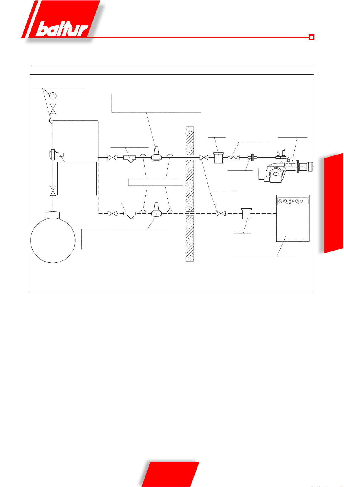
GENERAL DIAGRAM FOR REDUCING THE LPG PRESSURE
TO TWO STEPS FOR BURNER OR BOILER
Pressure gauge and pressure intake
1st step reducer;
Output = ~ 1 bar
Flow rate =
adequate
2st step reducer;
Tank
Note: Do not cover pipes and reducers with insulating material.
Output = ~ 30 mbar
Flow rate = about double the maximum
required by the user
2st step reducer;
Output = ~ 30 mbar
Flow rate = about double the
maximum required by the user
Filter (steam type)
(Pressure intake)
Filter (steam type)
Filter
Valve
8721/2
Burner
Vibration-proof joint
Fitting
ENGLISH
Filter
Free-standing or wallmounted boiler
29 / 36
0006081544_201408
Page 68

HOW TO FIND THE CAUSES OF IMPROPER WORKING AND HOW TO RECTIFY THEM
TYPE OF IRREGULARITY POSSIBLE CAUSE SOLUTION
Burner does not start.
(the appliance does not perform the
ignition program)
Defective ame with sparks. 1) Atomizing pressure too low
Flame badly shaped with smoke and
soot.
ENGLISH
Defective pulsating escaping ame or
receding from the combustion orice.
1) Thermostats (boiler/room) or pressure
switches open
2) Photoresistant-cell in short circuit
3) No voltage with an open isolating switch or
with a tripped max. contactor switch or line
voltage failure
4) Thermostat line not wired according to diagram or open thermostats
5) Failure inside the control-box
2) Too much combustion air
3) Dirty or worn nozzle
4) Water in the fuel
1) Insufcient combustion air ow
2) Dirty or worn nozzle
3) Combustion chamber unsuitably designed
or too small
4) Nozzle capacity too low with respect to combustion chamber volume
5) Unsuitable refractory coating (excessive
reduction in gap for ame)
6) Boiler or chimney ducts clogged
7) Atomization pressure low
1) Excessive draft (only if
there is a suction unit to the chimney)
2) Dirty or worn nozzle
3) Water in the fuel
4) Dirty disk
5) Excess combustion air
6) Air passage between disk and blast tube
1) Increase their value or wait until they activate
due to natural reduction of the temperature
or pressure
2) Replace it
3) Activate switches or wait for power to return
4) Check connections and thermostats
5) Replace it
1) Reset at proper value
2) Reduce combustion air ow
3) Clean or replace it
4) Remove it from the tank using a suitable pump.
(Never use the burner pump for this job)
1) Increase combustion air
2) Clean or replace it
3) Reduce the nozzle delivery rate to suit the
combustion chamber capacity (obviously the
thermal power will be lower than the required
one) or replace the boiler
4) Replace the nozzle, increasing its capacity
5) Modify ensuring that the instructions of the
boiler manufacturer are carefully followed
6) Clean them
7) Raise pressure to the prescribed value
1) Adjust the suction fan speed by changing the
pulley diameter
2) Clean or replace it
3) Remove it from the tank with a suitable pump
(never use the burner pump for this job)
4) Clean it
5) Reduce combustion air
6) Rectify the position of the blast tube.
Corrosion inside the boiler. 1) Boiler operating temperature too low (lower
than the dew point)
2) High sulphur content in the fuel Smoke temperature too low (below 130 °C).
Soot at the chimney exit. 1) Excessive cooling (below 130°C) of smoke
before exit outow, for an outside chimney not
adequately heat insulated or cold air inltration
30 / 36
0006081544_201408
1) Increase the operating temperature
2) Change grade of fuel if the boiler allows it.
1) Improve insulation and close any gap letting
cold air in.
Page 69

HOW TO FIND THE CAUSES OF BURNERS IMPROPER OPERATION AND HOW TO RECTIFY THEM
TYPE OF IRREGULARITY POSSIBLE CAUSE SOLUTION
The burner goes to lock-out with the ame
on (Red lamp on). The trouble is in the
ame control device.
1) Photoresistance severed or fouled with
smoke
2) Insufcient draught
3) Flame detector circuit interrupted
4) Dirty disk or head
1) Clean or replace it
2) Check all the smoke ducts in the boiler and
in the chimney
3) Replace the unit
4) Clean
The burner goes into lock-
out spraying liquid fuel but the
flame does not ignite (red light on).
The trouble is in the ignition device, providing the fuel is in a good condition (not
polluted with water or other impurities) and
sufciently atomized.
The burner goes into “lock-out”, gas ows,
but there is no ame (red light on). Fault in
ignition circuit.
The burner goes into lock-out spraying
liquid fuel but the ame does not ignite.
(Red light on).
The burner goes into “lock-out”, gas ows,
but there is no ame (red light on).
1) Ignition circuit severed.
2) The ignition transformer leads have dried
up.
3) The ignition transformer cables are not well
connected.
4) Ignition transformer severed.
5) The electrode tips are not at the correct
distance.
6) Electrodes discharge to earth because they
are dirty or their insulation is cracked: check
also underneath the insulator clamps.
1) Pump pressure is not normal
2) Water in the fuel
3) Excess combustion air
4) Air passage between disk and blast tube
5) Nozzle worn out or fouled
1) Air/gas ratio incorrect.
2) Gas piping has not bee n prope rly b led of
air (in the case of rst ignition).
3) The gas pressure is insufcient or exces-
sive.
4) Air passage bet ween disk and head too
narrow.
1) Check the entire circuit
2) Replace them
3) Tighten them
4) Replace it
5) Re-set them in the required position
6) Clean or replace them, if necessary
1) Re-set it
2) Remove it from the tank with a suitable
pump (never use the burner pump for
this job)
3) Reduce combustion air
4) Rectify the position of the combustion head
adjusting device
5) Clean or replace it
1) Check and adjust air/gas ratio.
2) Bleed the gas pipe again, with due caution.
3) Check the maximum gas pressure
value at the time of ignition (use a
water pressure gauge, if possible)
4) Adjust the disk/head opening.
ENGLISH
Noisy burner pump. 1) Pipe diameter too small
2) Air inltration in the pipes
3) Dirty lter
4) Excessive distance between the tank and
the burner or many accidental leakages
(elbows, curves, choking etc.)
5) Deteriorated exible pipes
31 / 36
0006081544_201408
1) Replace it according to instructions
2) Check and eliminate inltration’s
3) Remove and wash it
4) Adjust the length of the suction pipe and
shorten its distance
5) Replace them
Page 70

NOZZLE FLOW-RATE TABLE
Nozzle
G.P.H.
0.40 1.27 1.36 1.44 1.52 1.59 1.67 1.73 1.80 1.86 1.92 1.98 2.04 2.10 2.15 2.20 0.40
0.50 1.59 1.70 1.80 1.90 1.99 2.08 2.17 2.25 2.33 2.40 2.48 2.55 2.62 2.69 2.75 0.50
0.60 1.91 2.04 2.16 2.28 2.39 2.50 2.60 2.70 2.79 2.88 2.97 3.06 3.14 3.22 3.30 0.60
0.65 2.07 2.21 2.34 2.47 2.59 2.71 2.82 2.92 3.03 3.12 3.22 3.31 3.41 3.49 3.58 0.65
0.75 2.38 2.55 2.70 2.85 2.99 3.12 3.25 3.37 3.49 3.61 3.72 3.82 3.93 4.03 4.13 0.75
0.85 2.70 2.89 3.06 3.23 3.39 3.54 3.68 3.82 3.96 4.09 4.21 4.33 4.45 4.57 4.68 0.85
1.00 3.18 3.40 3.61 3.80 3.99 4.16 4.33 4.50 4.65 4.81
1.10 3.50 3.74 3.97 4.18 4.38 4.58 4.77 4.95 5.12 5.29 5.45 5.61 5.76 5.91 6.06 1.10
1.20 3.82 4.08 4.33 4.56 4.78 5.00 5.20 5.40 5.59 5.77 5.95 6.12 6.29 6.45 6.61 1.20
1.25 3.97 4.25 4.50 4.75 5.00 5.20 5.40 5.60 5.80 6.00 6.20 6.35 6.55 6.70 6.85 1.25
1.35 4.29 4.59 4.87 5.13 5.38 5.62 5.85 6.07 6.28 6.49 6.69 6.88 7.07 7.26 7.44 1.35
1.50 4.77 5.10 5.41 5.70 5.90 6.24 6.50 6.75 6.98 7.21 7.43 7.65 7.86 8.06 8.26 1.50
1.65 5.25 5.61 5.95 6.27 6.58 6.87 7.15 7.42 7.68 7.93 8.18 8.41 8.64 8.87 9.09 1.65
1.75 5.56 5.95 6.31 6.65 6.98 7.29 7.58 7.87 8.15 8.41 8.67 8.92 9.17 9.41 9.64 1.75
2.00 6.30 6.80 7.21 7.60 7.97 8.33 8.67 8.99
2.25 7.15 7.65 8.15 8.55 8.97 9.37 9.75 10.12 10.47 10.85 11.15 11.47 11.79 12.09 12.39 2.25
2.50 7.95 8.50 9.01 9.50 9.97 10.41 10.83 11.24 11.64 12.02 12.39 12.75 13.10 13.44 13.77 2.50
3.00 9.54 10.20 10.82 11.40 11.96 12.49 13.00 13.49 13.96 14.02 14.87 15.30 15.72 16.12 16.52 3.00
3.50 11.13 11.90 12.62 13.30 13.95 14.57 15.17 15.74 16.29 16.83 17.34 17.85 18.34 18.81 19.28 3.50
ENGLISH
4.00 12.72 13.60 14.42 15.20 15.94 16.65 17.33 17.99 18.62 19.23 19.82 20.40 20.95 21.50 22.03 4.00
4.50 14.31 15.30 16.22 17.10 17.94 18.73 19.50 20.24 20.95 21.63 22.30 22.95 23.57 24.19 24.78 4.50
5.00 15.90 17.00 18.03 19.00 19.93 20.82 21.67 22.48 23.27 24.04 24.78 25.49 26.19 26.87 27.54 5.00
5.50 17.49 18.70 19.83 20.90 21.92 22.90
6.00 19.00 20.40 21.63 22.80 23.92 24.98 26.00 26.98 27.93 28.84 29.73 30.59 31.43 32.25 33.04 6.00
6.50 20.67 22.10 23.44 23.70 25.91 27.06 28.17 29.23 30.26 31.25 32.21 33.14 34.05 34.94 35.80 6.50
7.00 22.26 23.79 25.24 26.60 27.90 29.14 30.33 31.48 32.58 33.65 34.69 35.69 36.67 37.62 38.55 7.00
7.50 23.85 25.49 27.04 28.50 29.90 31.22 32.50 33.73 34.91 36.05 37.16 38.24 39.29 40.31 41.31 7.50
8.30 26.39 28.21 29.93 31.54 33.08 34.55 35.97 37.32 38.63 39.90 41.13 42.32 43.48 44.61 45.71 8.30
9.50 30.21 32.29 34.25 36.10 37.87 39.55 41.17 42.72 44.22 45.67 47.07 48.44 49.77 51.06 52.32 9.50
10.50 33.39 35.69 37.86 40.06 41.73 43.74 45.41 47.20 48.90 50.50 52.00 53.50 55.00 56.40 57.80 10.50
12.00 38.20 40.80 43.30 45.60
13.80 43.90 46.90 49.80 52.40 55.00 57.50 59.80 62.10 64.20 66.30 68.40 70.40 72.30 74.30 76.00 13.80
15.30 48.60 52.00 55.20 58.10 61.00 63.70 66.30 68.80 71.10 73.60 75.80 78.00 80.20 82.20 84.30 15.30
17.50 55.60 59.50 63.10 66.50 69.80 72.90 75.80 78.70 81.50 84.10 86.70 89.20 91.70 94.10 96.40 17.50
19.50 62.00 66.30 70.30 74.10 77.70 81.20 84.50 87.70 90.80 93.70 96.60 99.40 102.20 104.80 107.40 19.50
21.50 68.40 73.10 77.50 81.70 85.70 89.50 93.20 96.70 100.10 103.40 106.50 109.60 112.60 115.60 118.40 21.50
24.00 76.30 81.60 86.50 91.20 95.70 99.90 104.00 107.90 111.70 115.40 118.90 122.40 125.70 129.00 132.20 24.00
28.00 89.00 95.20 101.00 106.40 111.60 116.60 121.30 125.90 130.30 134.60 138.70 142.80 146.70 150.50 154.20 28.00
30.00 95.40 102.00
Pump pressure
7 8 9 10 11 12 13 14 15 16 17 18 19 20 21
Nozzle output ow-rate
4.96 5.10 5.24 5.37 5.51 1.00
9.31 9.61 9.91 10.20 10.48 10.75 11.01 2.00
23.83 24.73 25.60 26.44 27.25 28.04 28.81 29.56 30.29 5.50
47.80 50.00 52.00 54.00 55.90 57.70 59.50 61.20 62.90 64.50 66.10 12.00
108.20 114.00 119.60 124.90 130.00 134.90 139.60 144.20 148.70 153.00 157.20 161.20 165.20 30.00
Nozzle
G.P.H.
1 mbar = 10 mmC.A. 100 Pa
1 kW = 860 kcal
Diesel density .........................................................= 0.820 / 0.830 NHV = 10150
Special fuel density .................................................= 0.900 NHV = 9920
Domestic fuel density (3.5°E) ................................= 0.940 NHV = 9700
Heavy fuel density (7.9°E) .....................................= 0.970 / 0.980 NHV = 9650
PCI = Minimum caloric value
32 / 36
0006081544_201408
Page 71
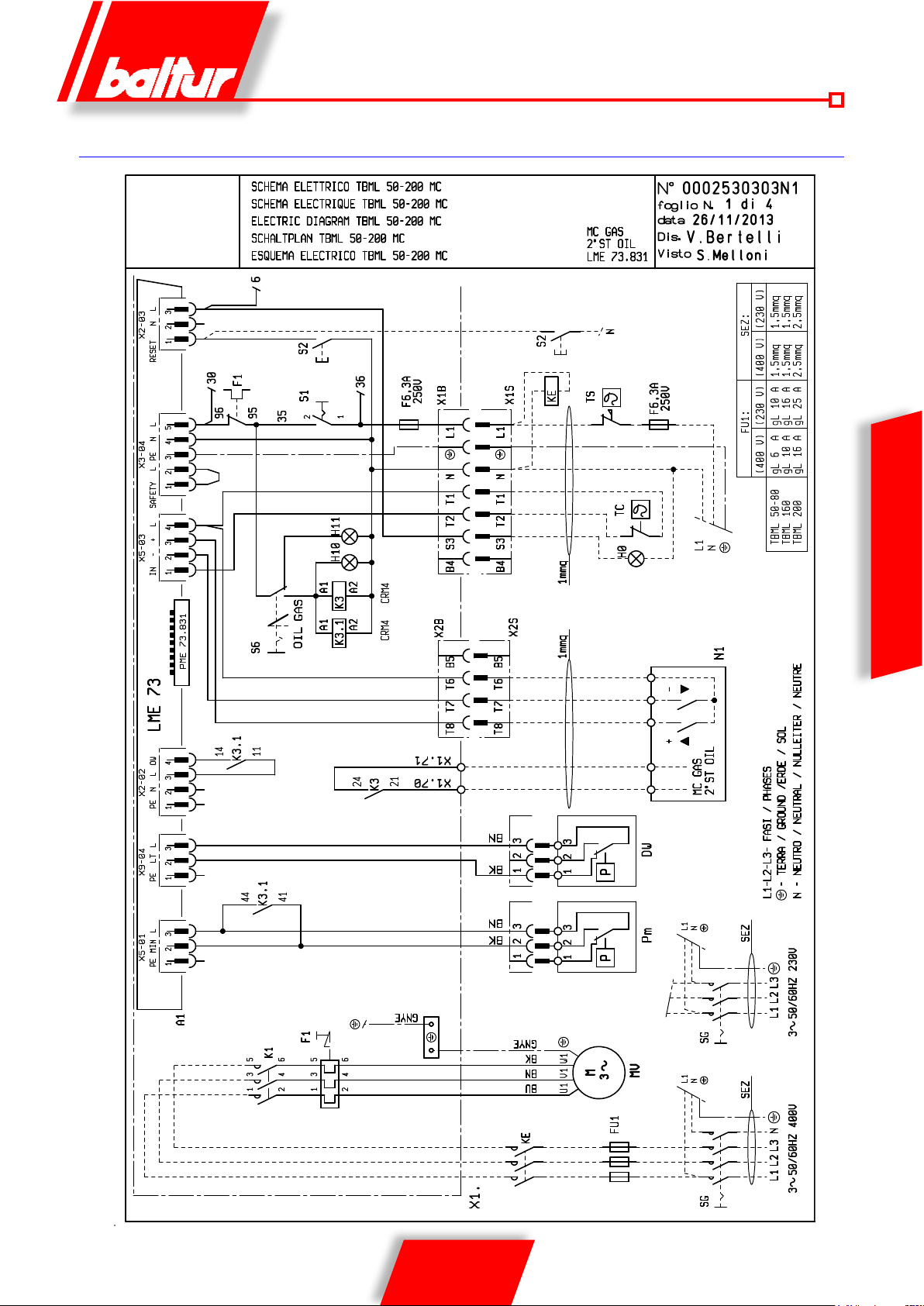
WIRING DIAGRAM
ENGLISH
33 / 36
0006081544_201408
Page 72
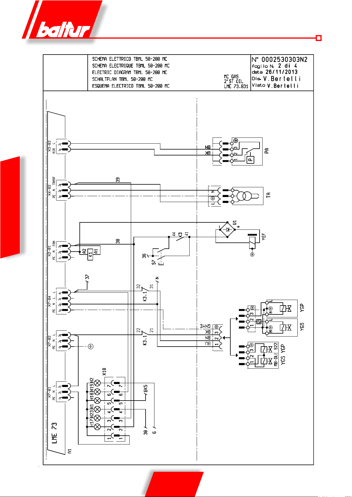
ENGLISH
34 / 36
0006081544_201408
Page 73
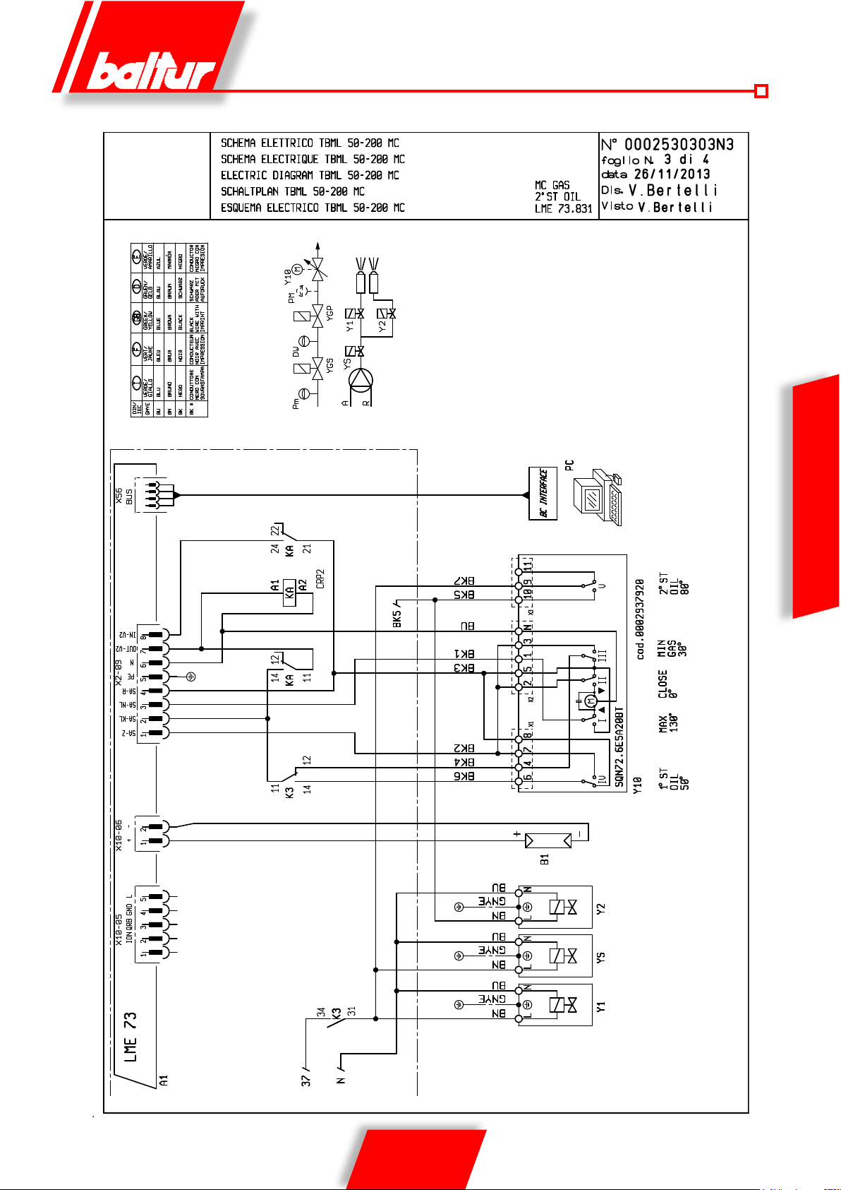
ENGLISH
35 / 36
0006081544_201408
Page 74

A1 EQUIPMENT
B1 UV PHOTOCELL
DW VALVE SEAL CONTROL PRESSURE SWITCH
F1 THERMAL RELAY
FU1 FUSES
H0 EXTERNAL SHUT-DOWN WARNING LIGHT
H1 OPERATION WARNING LIGHT
H10 OIL WARNING LIGHT
H11 GAS WARNING LIGHT
H17 VENTILATOR LAMP
H18 2ND STAGE LAMP
H19 MAIN VALVES ON LIGHT
H2 LOCK WARNING LIGHT
H23 TRANSFORMER LAMP
K1 MOTOR RELAY
K3-3.1 FUEL CHANGE RELAY
KA AUXILIARY RELAY
KE EXTERNAL CONTACTOR
MV FAN MOTOR
ENGLISH
PA AIR PRESSURE SWITCH
Pm MINIMUM PRESSURE SWITCH
S1 START/STOP SWITCH
S2 RELEASE BUTTON
S6 GAS-OIL SELECTOR
S7 TANK LOADING BUTTON
SG MAIN SWITCH
T2 2nd STAGE THERMOSTAT
TA IGNITION TRANSFORMER
TC BOILER THERMOSTAT
TS SAFETY THERMOSTAT
X1B/S POWER SUPPLY CONNECTOR
X2B/S 2ND STAGE CONNECTOR
X18 SYNOPTIC CONNECTOR
Y1 1
Y2 2
Y10 AIR SERVOMOTOR
YEF ELECTROFRICTION
YGP MAIN SOLENOID VALVE
YGS SAFETY SOLENOID VALVE
Z1 FILTER
st
STAGE ELECTROVALVE
nd
STAGE ELECTROVALVE
EN
DIN / IEC EN
GNYE GREEN/YELLOW
BU BLUE
BN BROWN
BK* BLACK
BK* BLACK CONNECTOR WITH OVERPRINT
EN A1 CONTROL BOX B1
36 / 36
0006081544_201408
Page 75

Page 76

Baltur S.p.A.
Via Ferrarese, 10
44042 Cento (Fe) - Italy
Tel. +39 051-6843711
Fax: +39 051-6857527/28
www.baltur.it
[email protected]
- Il presente catalogo riveste carattere puramente indicativo. La casa, pertanto, si riserva ogni possibilità di modica dei dati tecnici e quant’altro in esso riportato.
- Technical data in this brochure are given as information only. Baltur reserves the right to change specification, without notice.
 Loading...