

baltur TBG 45, TBG 45P, TBG 60, TBG 60P Use And Installation Manual

EN
SP FR TR
RU
CN
Maintenance,
use and
installation
manual
Manual de
mantenimiento,
uso e
instalación
Manuel
d’installation,
utilisation et
entretien
TBG 45
TBG 45 P
Bakım,
kullanım ve
montaj
kılavuzu
Инструкция по
установке,
эксплуатации и
техобслуживанию
维护、使
用及安装
手册
TBG 60
TBG 60 P
0006081362_200906


- Before using the burner for the rst time please carefully read the chapter “WARNINGS NOTES FOR THE USER : HOW
TO USE THE BURNER SAFELY” in this instruction manual, which is an integral and essential part of the product. The
works on the burner and on the esystem have to be carried out only by competent people.
- Read carefully the instructions before starting the burner and service it.
- The system electric feeding must be disconnected before starting working on it.
- If the works are not carried out correctly it is possible to cause dangerous accidents.
- Avant de commencer à utilise le brûleur,lire attentivement les recommandations de la notice “RECOMMANDATIONS A
L’ATTENTION DE L’UTILISATEUR POUR UN USAGE DU BRULEUR EN TOUTE SECURITE” jointe au manuel d’instructions et qui constitue une partie intégrante et essentielle du produit.
- Lire attentivement les instructions avant de mettre en fonction le bruleur et pour son entretien correct.
- Les travaux sur le bruleur et sur l’installation doivent etre executes seulement par du personnel qualie.
- L’alimentation electrique de l’installation doit etre debranche avant de commencer les travaux.
- Si les travaux ne sont pas executes correctement il y a la possibilite de causer de dangereux incidents.
E
N
G
L
I
S
H
F
R
A
Ç
A
- Antes de empezar a usar el quemador lea detenidamente el folleto “ADVERTENCIAS DIRIGIDAS AL USUARIO PARA
USAR CON SEGURIDAD EL QUEMADOR” que va con el manual de instrucciones y que constituye una parte integrante
y esencial del producto.
- Lea atentamente las instrucciones antes de poner en funcionamento los quemadores y efectuar las tareas de mantenimiento.
- Los trabajos que se efectúen al quemador y a la instalación deben ser efectuados sólamente por personal cualicado.
- La alimentación eléctrica de la instalación se debe desconectar antes de iniciar los trabajos.
- Si los trabajos no son efectuados correctamente se corre el riesgo de que se produzcan accidentes peligrosos.
- Brülörü ilk defa kullanmadan önce lütfen ürünün bütünleşik ve lüzumlu bir parçası olarak brülörle beraber verilen bu kul-
lanma kılavuzu içinde yer alan “BRÜLÖRÜN GÜVENLE KULLANILMASI İÇİN KULLANICIYA UYARI NOTLARI” bölümünü
dikkatle okuyunuz. Brülör ve sistem üzerindeki çalışmalar sadece yetkili personel tarafından yapılmalıdır.
- Brülörü çalıştırmadan veya onarımına başlamadan önce kullanma kılavuzunu dikkatle okuyunuz.
I
S
E
S
P
A
Ñ
O
L
T
ü
- Brülör üzerinde onarıma başlamadan önce sistemin elektrik beslemesi kesilmelidir.
- Talimatlara titizlikle uyulmayıp, çalışmalar düzgün yürütülmediği tehlikeli kazaların oluşması mümkündür.
0006081362_200906
r
k
ç
e


- Перед началом эксплуатации горелки внимательноознакомьтесьс содержанием данной брошюры
“ПРЕДУПРЕЖДЕНИЯПОЛЬЗОВАТЕЛЮПО БЕЗОПАСНОЙЭКСПЛУАТАЦИИГОРЕЛКИ”,которая входитв
комплектинструкции,и,котораяявляетсянеотъемлемойиосновнойчастьюизделия.
- Передпускомгорелкииливыполнениемтехобслуживаниянеобходимовнимательнопрочитатьинструкции.
- Работынагорелкеивсистемедолжнывыполнятьсяквалифицированнымиработниками.
- Передосуществлениемлюбыхработэлектрическоепитаниенеобходимовыключить.
- Работы,выполненныенеправильнымобразом,могутпривестикопаснымавариям.
注意
- 对燃烧器和系统的操作只能由合格的工作人员来执行
- 启动燃烧器和进行维护保养前,请仔细阅读本说明手册。
Р
У
С
С
К
И
Й
- 在对燃烧器的电气系统进行操作前,请先切断供电电源。
- 如果操作或处理不当,可能会引起危险事故。
中
文
0006081362_200906


Statement of Conformity
We hereby declare under our own responsibility, that our “CE” marked products Series:
Sparkgas…; BTG…; BGN…; Minicomist…; Comist…; RiNOx…, BT…; BTL…;
GI…; GI…Mist; PYR…; TS…, TBG...,
Description:
domestic and industrial blown air burners red by gas, oil and dual fuel respect the
minimal regulation of the European Directives:
• 90/396/EEC (G.A.D)
• 92/42/EEC (B.E.D)
• 89/336/EEC (E.M.C. Directive)
• 73/23/EEC (Low Voltage Directive)
• 98/37 EEC (Machinery Directive)
and have been designed and tested in accordance with the European Standards:
• EN 676 (gas and dual fuel, gas side)
• EN 267 (light oil and dual fuel, oil side)
• EN 60335-1, 2003
• EN 50165: 1997 + A1:2001
• EN 55014 -1 (1994) and –2 (1997)
Surveillance accordingly Gas Appliances Directive 90/396/EEC made by:
CE0085 - DVGW
E
N
G
L
I
S
H
The Vice President and Managing Director:
Dr. Riccardo Fava
INDEX.................................................................................................................................................PAGE
- Warning notes for the user .................................................................................................................“ 2
- Technicalspecications......................................................................................................................“ 4
- Application of the burner to boiler - Assembling the gas train ..........................................................“ 8
- Wiring diagram ...................................................................................................................................“ 9
- Descriptions of operations .................................................................................................................“ 10
- Gas burner control devices ................................................................................................................“ 11
- Methane gas ignition and adjustment ................................................................................................“ 12
- Ionisation current adjustment .............................................................................................................“ 13
- Electrodes/ ionisation probe adjustment - Combustion head air adjustment .....................................“ 16
- Servomotor cam regulation ................................................................................................................“ 15
- Maintenance.......................................................................................................................................“ 16
- Preparationforconnectionwithtrainturnedupward-Twostagegas-redburners-Singlestage
air burner adjustment scheme............................................................................................................“ 17
- Problem - Cause - Solution ................................................................................................................“ 18
- Electric diagram .................................................................................................................................“ 115
1 / 18
0006081362_200906

WARNING NOTES FOR THE USER HOW TO USE THE BURNER SAFELY
E
FOREWORD
These warning notes are aimed at ensuring the safe use of the components of heating systems for civil use and the production of hot water. They indicate how to act to
avoid the essential safety of the components being compromised by incorrect or erroneous installation and by improper or unreasonable use. The warning notes provided
N
in this guide also seek to make the consumer more aware of safety problems in general, using necessarily technical but easily understood language. The manufacturer is
not liable contractually or extra contractually for any damage caused by errors in installation and in use, or where there has been any failure to follow the manufacturer’s
G
instructions.
L
GENERAL WARNING NOTES
• The instruction booklet is an integral and essential part of the product and must be given to the user. Carefully read the warnings in the booklet as they contain important
I
information regarding safe installation, use and maintenance. Keep the booklet to hand for consultation when needed.
• Equipment must be installed in accordance with current regulations, with the manufacturer’s instructions and by qualied technicians. By the term ‘qualied technicians’
S
H
is meant persons that are competent in the eld of heating components for civil use and for the production of hot water and, in particular, assistance centres authorised
by the manufacturer. Incorrect installation may cause damage or injury to persons, animals or things. The manufacturer will not in such cases be liable.
• After removing all the packaging make sure the contents are complete and intact. If in doubt do not use the equipment and return it to the supplier. The packaging ma-
terials (wooden crates, nails, staples, plastic bags, expanded polystyrene, etc.) must not be left within reach of children as they may be dangerous to them. They should
also be collected and disposed on in suitably prepared places so that they do no pollute the environment.
• Before carrying out any cleaning or maintenance, switch off the equipment at the mains supply, using the system’s switch or shut-off systems.
• If there is any fault or if the equipment is not working properly, de-activate the equipment and do not attempt to repair it or tamper with it directly. In such case get in touch
with only qualied technicians. Any product repairs must only be carried out by BALTUR authorised assistance centres using only original spare parts. Failure to act as
above may jeopardise the safety of the equipment. To ensure the efciency and correct working of the equipment, it is essential to have periodic maintenance carried out
by qualied technicians following the manufacturer’s instructions.
• If the equipment is sold or transferred to another owner or if the owner moves and leaves the equipment, make sure that the booklet always goes with the equipment so
it can be consulted by the new owner and/or installer.
• For all equipment with optionals or kits (including electrical), only original accessories must be used.
BURNERS
• This equipment must be used only for its expressly stated use: applied to boilers, hot air boilers, ovens or other similar equipment and not exposed to atmospheric agents.
Any other use must be regarded as improper use and hence dangerous.
• The burner must be installed in a suitable room that has ventilation in accordance with current regulations and in any case sufcient to ensure correct combustion
• Do not obstruct or reduce the size of the burner’ air intake grills or the ventilation openings for the room where a burner or a boiler is installed or dangerous mixtures of
toxic and explosive gases may form.
• Before connecting the burner check that the details on the plate correspond to those of the utility supplies (electricity, gas, light oil or other fuel).
• Do not touch hot parts of the burner. These, normally in the areas near to the ame and any fuel pre-heating system, become hot when the equipment is working and
stay hot for some time after the burner has stopped.
• If it is decided not to use the burner any more, the following actions must be performed by qualied technicians:
a) Switch off the electrical supply by disconnecting the power cable from the master switch.
b) Cut off the fuel supply using the shut-off valve and remove the control wheels from their position.
c) Render harmless any potentially dangerous parts.
Special warning notes
• Check that the person who carried out the installation of the burner xed it securely to the heat generator so that the ame is generated inside the combustion chamber
of the generator itself.
• Before starting up the burner, and at least once a year, have qualied technicians perform the following operations:
a) Set the burner fuel capacity to the power required by the heat generator.
b) Adjust the combustion air ow to obtain combustion yield of at least the minimum set by current regulations.
c) Carry out a check on combustion to ensure the production of noxious or polluting unburnt gases does not exceed limits permitted by current regulations.
d) Check the adjustment and safety devices are working properly.
e) Check the efciency of the combustion products exhaust duct.
f) Check at the end of the adjustments that all the adjustment devices mechanical securing systems are properly tightened.
g) Make sure that the use and maintenance manual for the burner is in the boiler room.
• If the burner repeatedly stops in lock-out, do not keep trying to manually reset but call a qualied technicians to sort out the problem.
• The running and maintenance of the equipment must only be carried out by qualied technicians, in compliance with current regulations.
2 / 18
0006081362_200906

WARNING NOTES FOR THE USER HOW TO USE THE BURNER SAFELY
ELECTRICAL SUPPLY
• The equipment is electrically safe only when it is correctly connected to an efcient ground connection carried out in accordance with current safety regulations. It is
necessary to check this essential safety requirement. If in doubt, call for a careful electrical check by a qualied technicians, since the manufacturer will not be liable for
any damage caused by a poor ground connection.
• Have qualied technicians check that the wiring is suitable for the maximum power absorption of the equipment, as indicated in the technical plate, making sure in
particular that the diameter of cables is sufcient for the equipment’s power absorption.
• Adapters, multiple plugs and extension cables may not be used for the equipment’s power supply.
• An ominpolar switch in accordance with current safety regulations is required for the mains supply connection.
• The electrical supply to the burner must have neutral to ground connection. If the ionisation current has control with neutral not to ground it is essential to make a
connection between terminal 2 (neutral) and the ground for the RC circuit.
• The use of any components that use electricity means that certain fundamental rules have to followed, including the following:
- do not touch the equipment with parts of the body that are wet or damp or with damp feet
- do not pull on electrical cables
- do not leave the equipment exposed to atmospheric agents (such as rain or sun etc.) unless there is express provision for this.
- do not allow the equipment to be used by children or inexpert persons.
• The power supply cable for the equipment not must be replaced by the user. If the cable gets damaged, switch off the equipment, and call only on qualied technicians
for its replacement.
• If you decide not to use the equipment for a while it is advisable to switch off the electrical power supply to all components in the system that use electricity (pumps,
burner, etc.).
GAS, LIGHT OIL, OR OTHER FUEL SUPPLIES
General warning notes
• Installation of the burner must be carried out by qualied technicians and in compliance with current law and regulations, since incorrect installation may cause damage
to person, animals or things, for which damage the manufacturer shall not can be held responsible.
• Before installation it is advisable to carry out careful internal cleaning of all tubing for the fuel feed system to remove any residues that could jeopardise the proper
working of the burner.
• For rst start up of the equipment have qualied technicians carry out the following checks:
• If you decide not to use the burner for a while, close the tap or taps that supply the fuel.
Special warning notes when using gas
• Have qualied technicians check the following:
a) that the feed line and the train comply with current law and regulations.
b) that all the gas connections are properly sealed.
• Do not use the gas pipes to ground electrical equipment.
• Do not leave the equipment on when it is not in use and always close the gas tap.
• If the user of is away for some time, close the main gas feed tap to the burner.
• If you smell gas:
a) do not use any electrical switches, the telephone or any other object that could produce a spark;
b) immediately open doors and windows to create a current of air that will purify the room;
c) close the gas taps;
d) ask for the help of qualied technicians.
• Do not block ventilation openings in the room where there is gas equipment or dangerous situations may arise with the build up of toxic and explosive mixtures.
E
N
G
L
I
S
H
FLUES FOR HIGH EFFICIENCY BOILERS AND SIMILAR
It should be pointed out that high efciency boilers and similar discharge combustion products (fumes) at relatively low temperatures into the ue. In the above situation,
traditional ues (in terms of their diameter and heat insulation) may be suitable because the signicant cooling of the combustion products in these permits temperatures
to fall even below the condensation point. In a ue that works with condensation there is soot at the point the exhaust reaches the atmosphere when burning light oil or
heavy oil or the presence of condensate water along the ue itself when gas is being burnt (methane, LPG, etc.). Flues connected to high efciency boilers and similar must
therefore be of a size (section and heat insulation) for the specic use to avoid such problems as those described above.
3 / 18
0006081362_200906
E
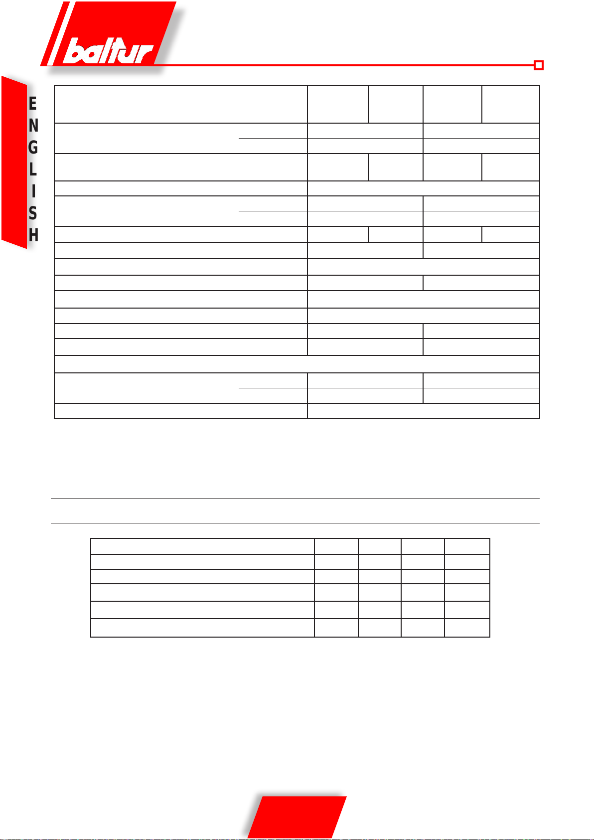
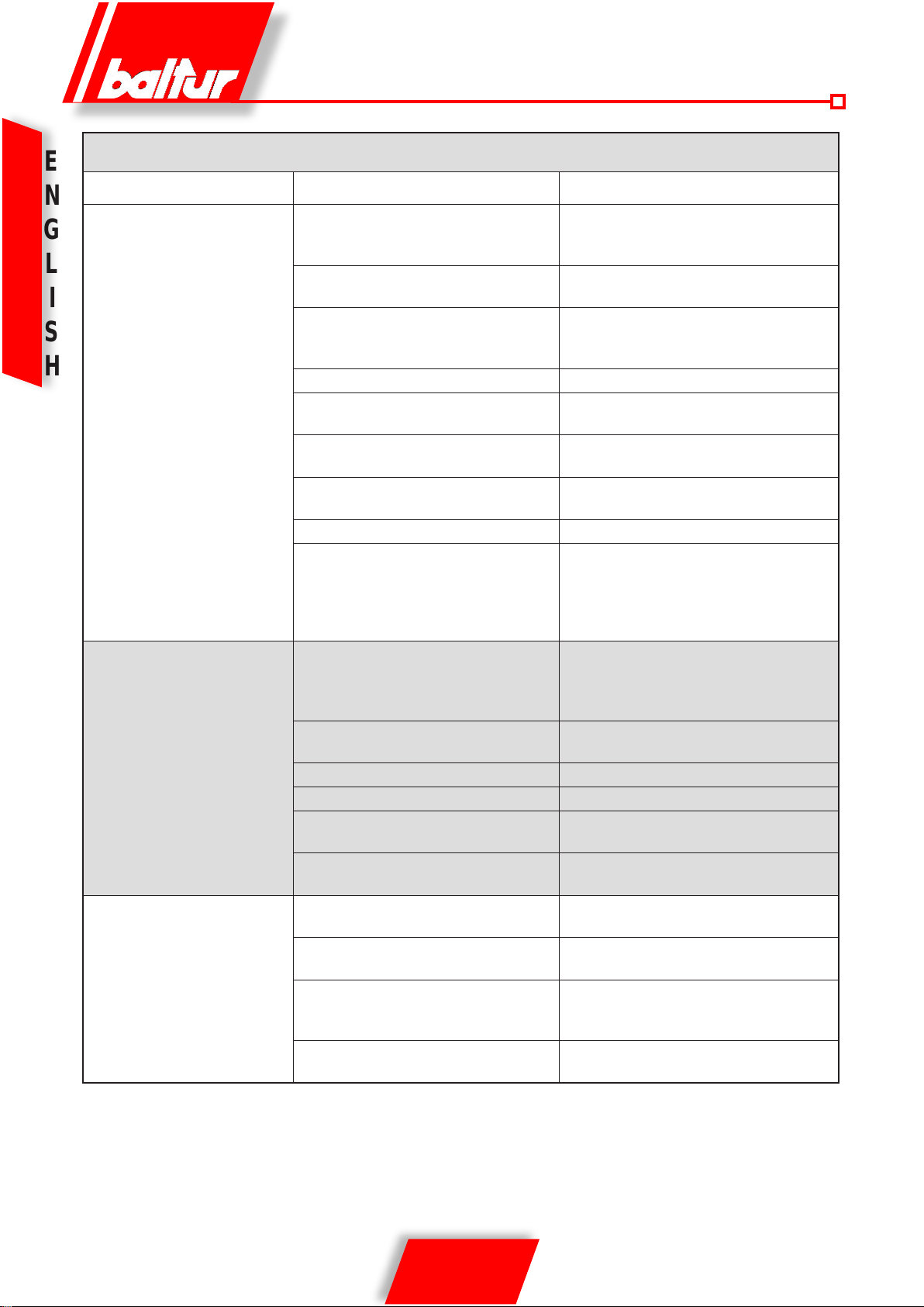
TECHNICAL DATA
TBG 45 TBG 45P TBG 60 TBG 60P
N
THERMIC CAPACITY
G
OPERATION One stage Two stages One stage Two stages
L
NOx EMMISION mg/kWh < 80 (Classe III secondo EN 676)
I
MOTOR
S
ABSORBED ELECTRICAL POWER* kW 0,67 0,69 0,93 0,96
H
line fuse A / 400 V - - 4
IGNITION TRANSFORMER
VOLTAGE 1N ~ 230 V ±10%- 50 Hz 3N ~ 400 V ±10%- 50 Hz
PROTECTION RATING IP 44
FLAME DETECTOR IONIZATION PROBE
NOISE** dBA 73 75
WEIGHT kg 40 42
Natural Gas (G 20)
FLOW RATE
GAS PRESSURE MAX mbar 360
MAX kW 450 600
MIN kW 100 120
kW 0,50 0,75
r.p.m. 2730 2800
26 kV - 40 mA - 230/240 V - 50/60 Hz
MAX m³n/h 45,3 60,3
MIN m³n/h 10,1 12,1
*) Total absorption at start with ignition transformer on. .
**) Noiselevelsmeasuredbythemanufacturerinthelaboratorywithburnerrunningontestboiler,atmaximumnominalthermaloutput.
STANDARD ACCESSORIES
TBG 45 TBG 45P TBG 60 TBG 60P
BURNER FIXING FLANGE 2 2 2 2
ISOLATING GASKET 1 1 1 1
STUD BOLTS N° 4 M 12 N° 4 M 12 N° 4 M 12 N° 4 M 12
EXAGONAL NUTS N° 4 M 12 N° 4 M 12 N° 4 M 12 N° 4 M 12
FLAT WASHERS N° 4 Ø 12 N° 4 Ø 12 N° 4 Ø 12 N° 4 Ø 12
4 / 18
0006081362_200906

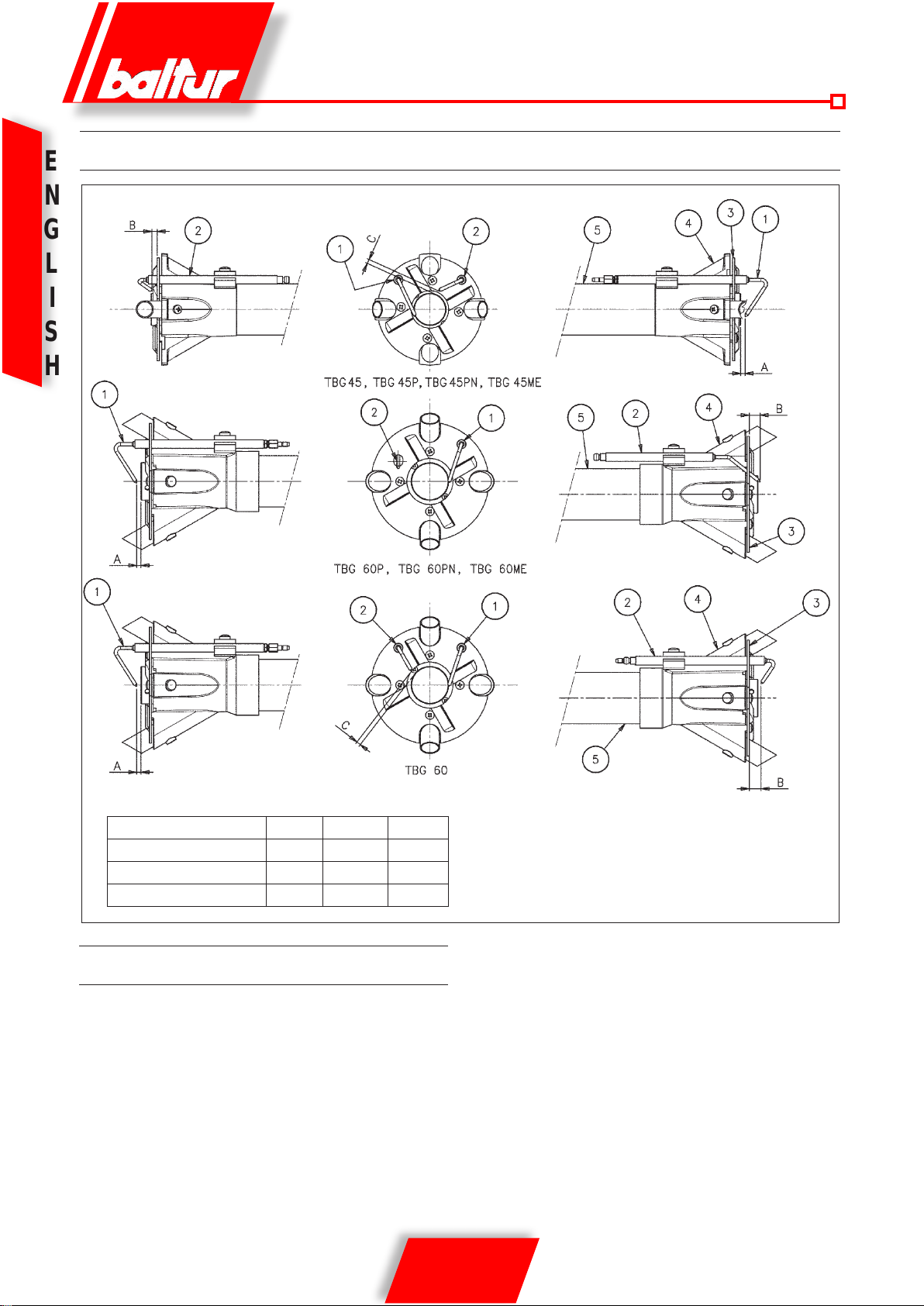
OVERALL DIMENSIONS
1) Combustion head
2) Gasket
3) Burner attachment ange
4) Combustion Head adjustment device
5) Cover
6) Gas train connector ange
7) Electrical panel
8) Motor
9) Air adjustment servomotor
9a) Manual air adjustment (TGB 45/60)
10) Air pressure switch
E
N
G
L
I
S
H
MODEL A A1 A2 B B1 B6 C D D E F I L L M N
min max Ø Ø min max
TBG 45 550 270 280 435 325 160 880 140 300 137 133 215 200 245 M12 145
TBG 45P 550 270 280 435 325 160 920 140 300 137 133 215 200 245 M12 145
TBG 60 550 270 280 455 325 160 880 140 300 156 152 260 225 300 M12 160
TBG 60P 550 270 280 455 325 160 920 140 300 156 152 260 225 300 M12 160
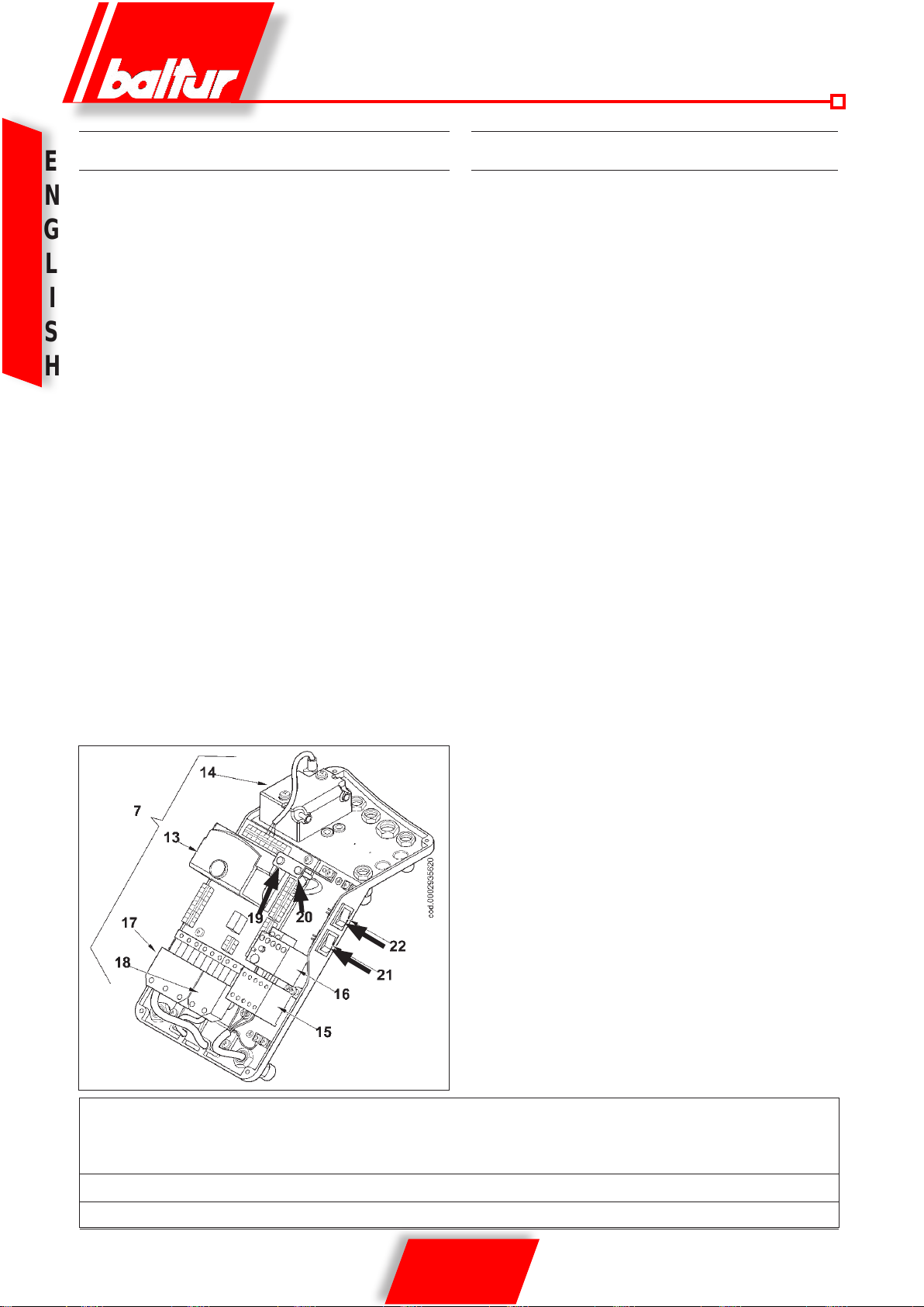
ELECTRICAL BOX COMPONENTS
13) Equipment
14) Ignition transformer
15) Motor contactor (only for three-phase power supply)
16) Thermal relay (only for three-phase power supply)
17) 7 pole plug
18) 4 pole plug
19) Led burner on
20) Led burner lock-out
21) Un-lock switch button
22) ON/OFF switch
5 / 18
0006081362_200906
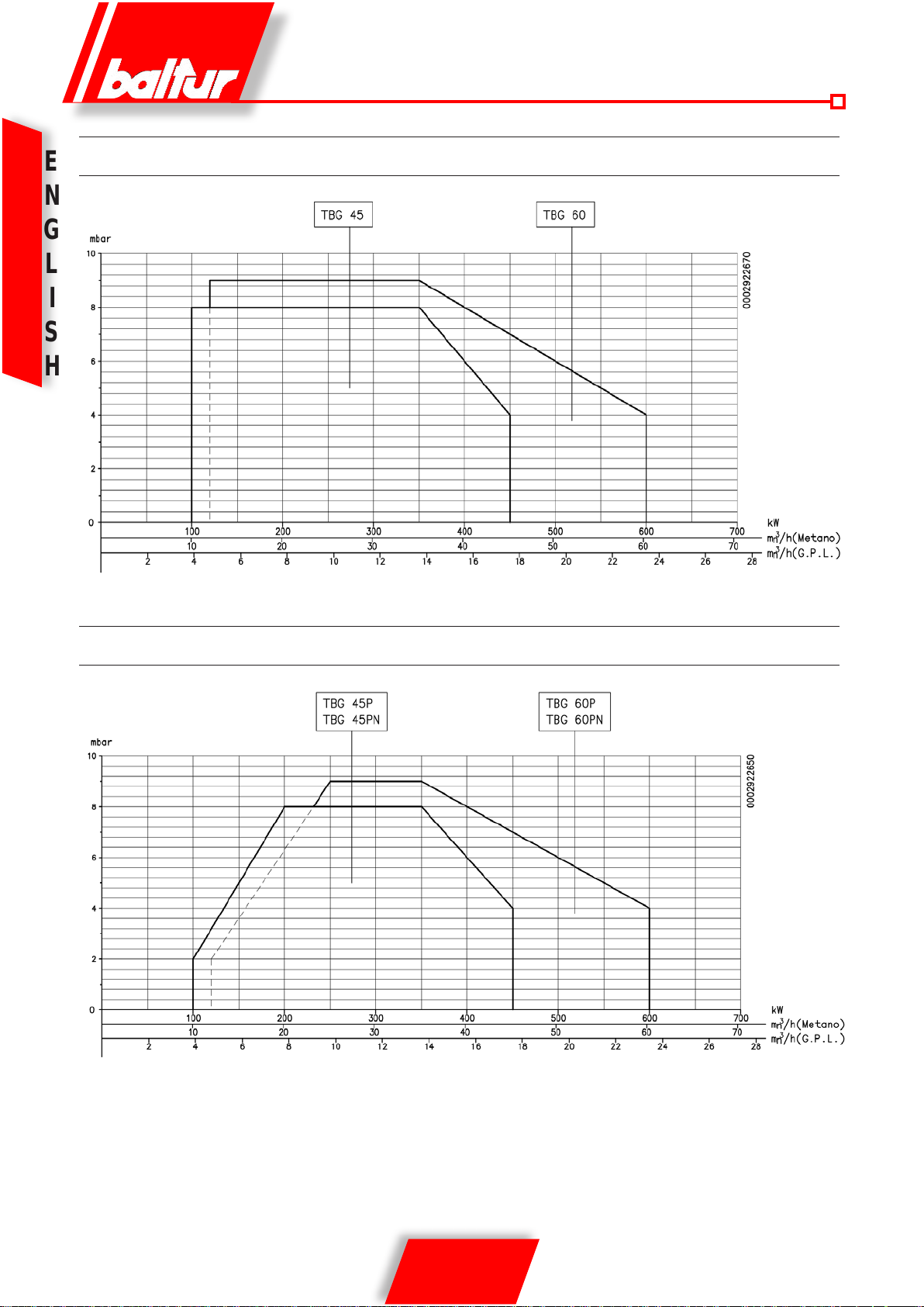
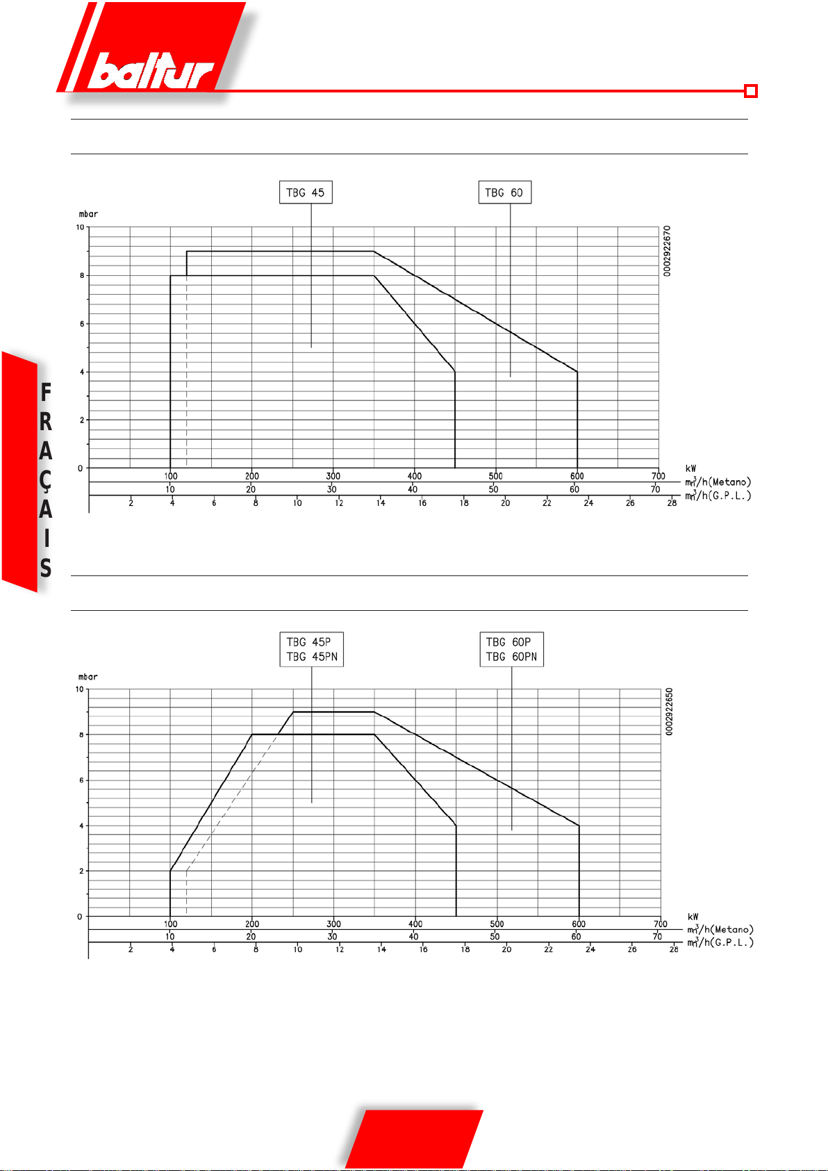
WORKING FIELD TBG 45 / 60 SINGLE STAGE
E
N
G
L
I
S
H
WORKING FIELD TBG 45P / 60P TWO STAGE
The working elds are obtained from test boilers corresponding
to the standard EN676 and are indicatively for the combination
burner-boiler. For correct working of the burner the size of the
combustion chamber must correspond to current regulations; if
not the manufacturers must be consulted.
6 / 18
0006081362_200906
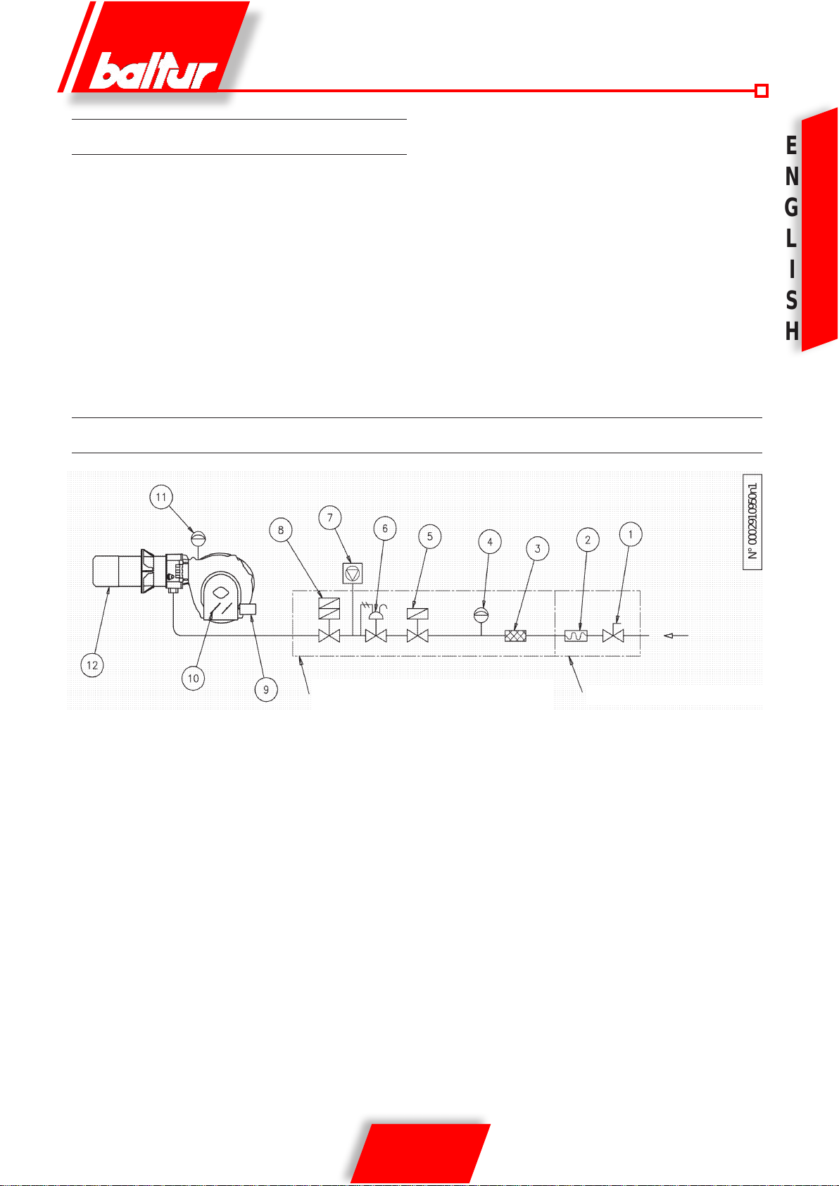
POWER SUPPLY LINE
N° 0002910950n1
The gas supply scheme is shown in the diagram below. The gas
train is certied in accordance with regulations EN 676 and is supplied separately from the burner.
A manual shut off valve and anti-vibration joint must be installed
upstream of the gas valve, as shown in the diagram.
In the case of a gas train with a pressure regulator that is not incorporated in a monoblock valve,
we consider it useful to give the following practical advice regarding the installation of accessory components to the gas piping
close to the burner:
GENERAL GAS BURNER SYSTEM
1) To prevent severe drops in pres-sure on ignition it is advisble
to have a length of piping of 1.5 to 2 metres between the point
of application of the stabiliser or pressure reducer and the
burner. This pipe must have a diameter equal to or greater
than the connector to the burner.
2) For the better working of the pressure regulator it is advisable
to apply it to the horizontal piping, after the lter. The gas pressure regulator must be adjusted when working at maximum
capacity and actually used by the burner. The delivery pressure must be adjusted to a level slightly below the maximum
obtainable. (that which is obtained when the regulation screw
is turned almost to the end); in the specic case, when the
regulation screw is tightened, the output pressure from the
regulator increases and when it is loosened it decreases.
E
N
G
L
I
S
H
Legend
1) Manual shut off valve
2) Anti-vibration joint
3) Gas lter
4) Minimum gas pressure switch
5) Safety valve
6) Pressure regulator
Gas train
supplied by the manufacturer
7) Valves seal control device (obligatory for burner with maxi-
mum nominal thermal out-put over 1200 kW)
8) Two-stage working valve
9) Control servomotor
10) Air adjustment gate
11) Air pressure switch
12) Combustion head
The job of the installer
7 / 18
0006081362_200906
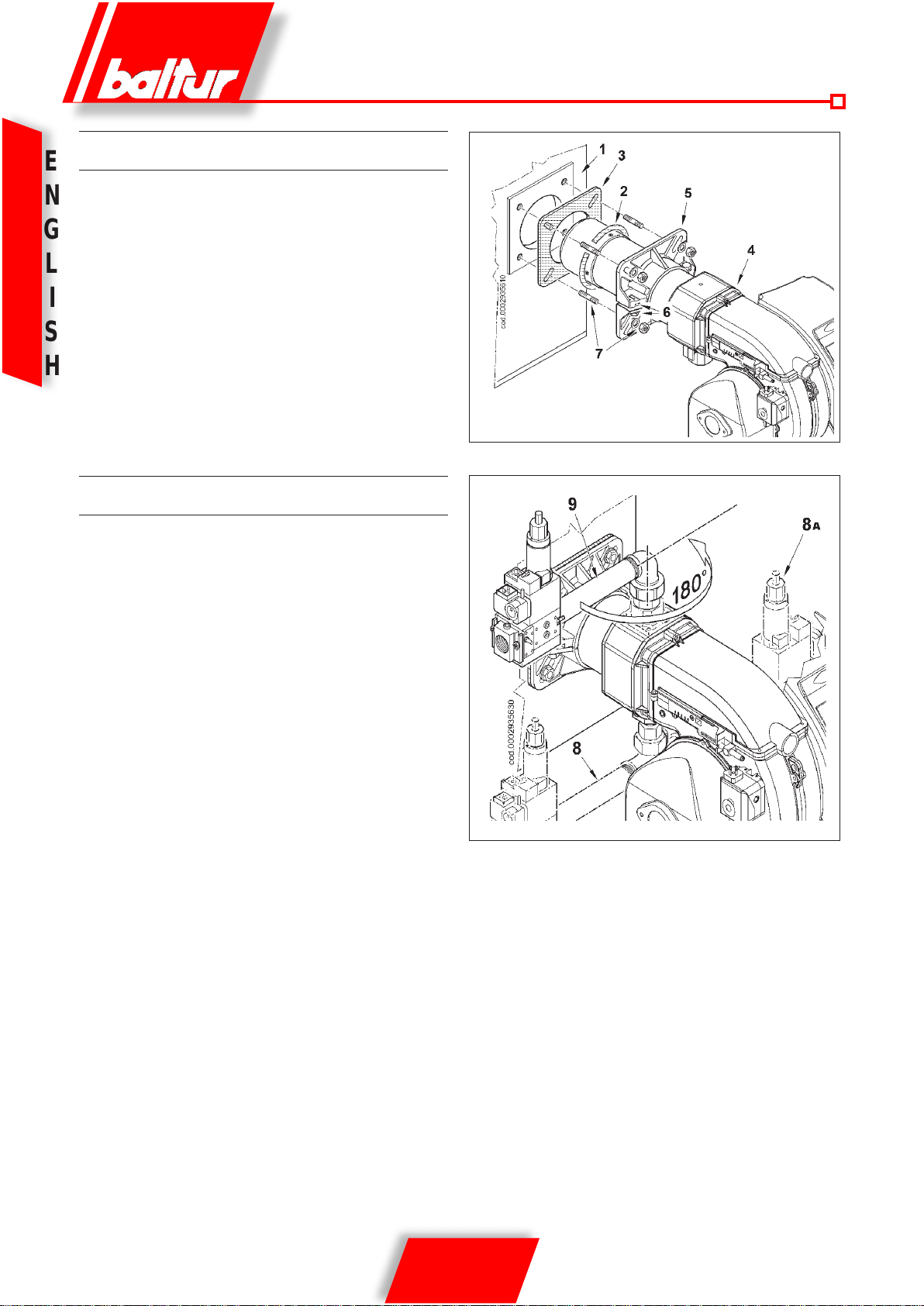
APPLICATION OF BURNER TO BOILER
E
- Position insulating seal 3 on the sleeve, placing cord 2 between
N
G
L
I
S
H
the ange and the seal.
- slacken screws “6”,
adjust the position of connection ange “5” so that the combustion head penetrates the furnace up to the length recommended by the generator manufacturer.
- Fasten the burner 4 to the boiler 1 by means of the stud bolts,
washers and the nuts provided 7.
Note:Competely seal the space between the tube unit of the
burner and the hole in the refractory panel using suitable materials to do so.
ASSEMBLING THE GAS TRAIN
There are different ways of assembling the valve train, 8, 8a and 9
as shown in the drawing. The burner is supplied with the gas train
connection facing downward. If you wish to invert the direction of
train entrance to allow the valve set to be assembled in conguration
9, follow the procedure described in the section entitled: “Preparation
for connection with train turned upward”.
Choose the most rational position for the set-up of the boiler room
and the position in which the gas pipe arrives.
8 / 18
0006081362_200906
WIRING DIAGRAM
The three-phase power supply line must have a switch with fuses.
The regulations further require a switch on the burner’s power supply line, outside the boiler room and in an easily accessed position.
For the electrical connections (line and thermostats), follow the
wiring diagram enclosed. To carry out the connection of the burner
to the power supply line proceed as follows:
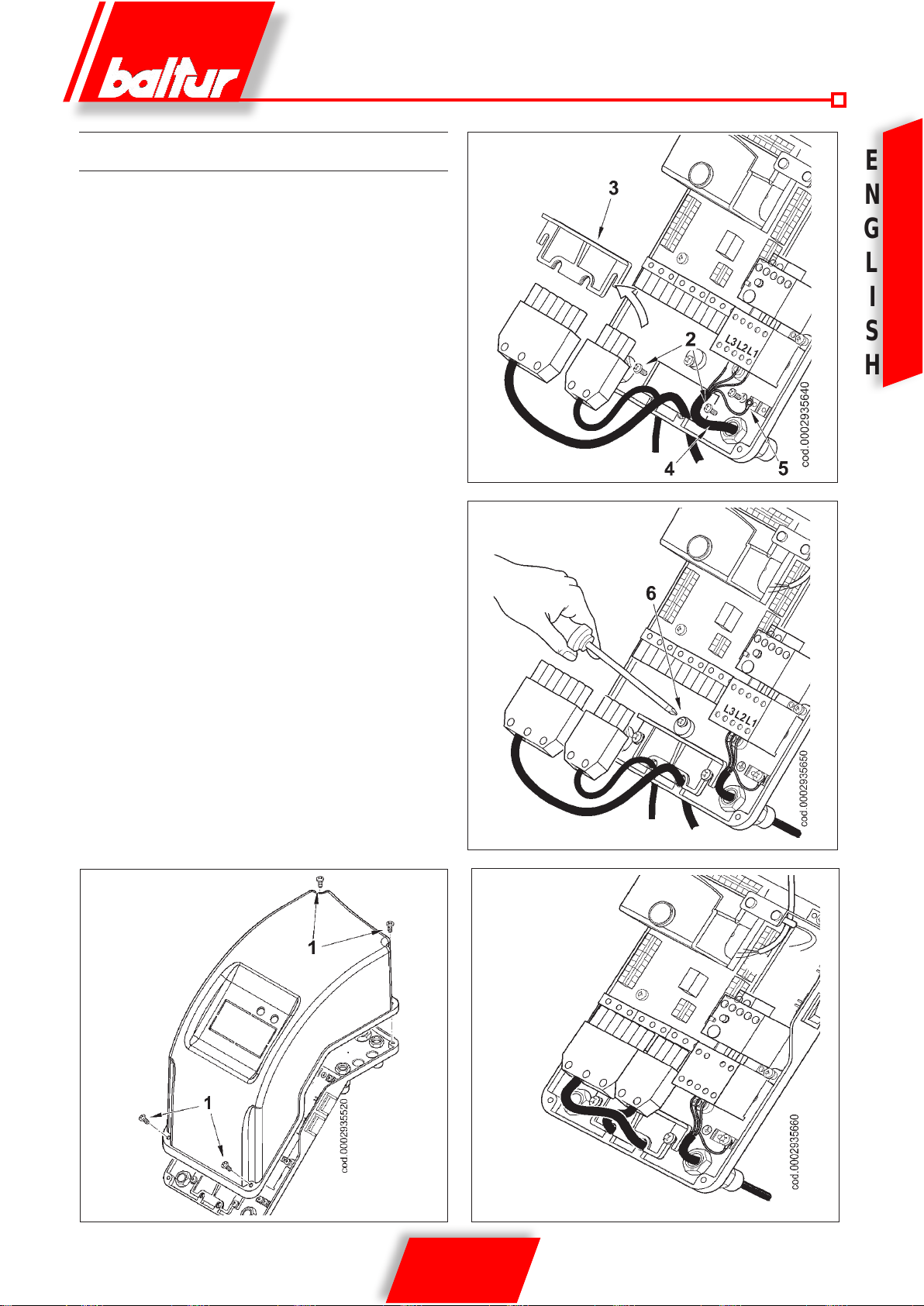
- Remove the lid by unscrewing the 4 screws (1) in gure 1. In
this way the burner’s electrical panel can be accessed.
E
N
G
L
I
S
- Slacken screws (2) and, after removing the cable oat plate
(3), pass the two 7 and 4 pole plugs through the hole (see gure 2). In the case of a three-phase burner, connect the power
supply cables (4) to the contactor, x the ground cable (5) and
tighten its cable holder.
- Reposition the cable oat plate as in gure 3. Turn the cam (6)
so that the oat exerts sufcient pressure on the two cables,
then tighten the screws that fasten the cable oat. Finally, connect the two 7 and 4-pole plugs.
IMPORTANT: the housings for the cables for the 7 and 4-pole
plugs are respectively for cable Ø 9.5-10 mm and
Ø 8.5-9 mm, this to make sure the protection rating
of IP 44 (IEC EN 60529) for the electrical panel.
- To reclose the electrical panel lid, tighten the 4 screws (1) with
a torque of about 5 Nm to ensure the correct seal.
IMPORTANT: only qualied technicians may open the bur-
ner’s electrical panel.
H
Fig. 2
Fig. 1
Fig. 3
Fig. 4
9 / 18
0006081362_200906
DESCRIPTION OF TBG 45 / 60 OPERATION
E
When the main switch and the I/O switch (22) on the electrical
N
panel are closed, if the thermostats are closed, voltage will reach
the command and control device, which starts up the burner (led
G
19 comes on).
This turns on the fan motor for preventilation of the combustion
L
chamber.
The ignition transformer then comes on, and 2 seconds later the
I
gas valves open.
S
The main valve, which has two stages, has a device for adjusting
gas delivery for the rst and second ame.
H
The safety valve is an ON/OFF valve.
Combustion air may be adjusted manually using the air lock (see
section entitled “Diagram for adjustment of air in single-stage burner
TBG 45-60”).
As the burner is ON/OFF, the position of the air lock must be regulated for operation at maximum capacity.
The presence of the ame, detected by the control device, permits
continuation and completion of ignition, turning off the ignition
transformer.
The second ame then comes on (the second stage in the main
valve opens).
If there is no ame, the appliance shuts down in “safety lock-out”
mode (led 20 comes on) within 3 seconds of the opening of the rst
ame on the main valve.
In “safety lock-out” mode the valves are closed again immediately.
To release the appliance from safety lock-out mode, press button
(21) on the electrical panel.
DESCRIPTION OF TBG 45P - 60P OPERATION
When the main switch and the I/O switch (22) on the electrical
panel are closed, if the thermostats are closed, voltage will reach
the command and control device, which starts up the burner (led
19 comes on).
This turns on the fan motor for preventilation of the combustion
chamber. At the same time, the servomotor commanding the air
lock opens in the position corresponding to the second ame, so
preventilation takes place with the air lock in the second ame
position.
At the end of the preventilation phase, the air lock is returned to
the rst ame position, then the ignition transformer comes on
and, 2 seconds later, the gas valves open.
The main valve, which has two stages, has a device for adjusting
gas delivery for the rst and second ame.
The safety valve is an ON/OFF valve.
The air lock is operated by an electric servomotor(see 0002934711).
Keep in mind that when the burner is locked out because the ther-
mostat is tripped, the servomotor returns the air lock to the closed
position.
The presence of the ame, detected by the control device, permi-
ts continuation and completion of ignition, turning off the ignition
transformer. The second ame then comes on (combustion air is
increased and the second stage of the main valve opens).
If there is no ame, the appliance shuts down in “safety lock-out”
mode (led 20 comes on) within 3 seconds of the opening of the
rst ame on the main valve.
In “safety lock-out” mode the valves are closed again immedia-
tely.
To release the appliance from safety lock-out mode, press button
(21) on the electrical panel..
Equipment or Safety Preventilation Pre- Post- Opening time time travel time travel
programmer time time ignition ignition 1st ame valve opening closing
s s s s s s s
LME 22.331A2 3 30 2 2 11 12 12
LME 22.233A2 3 30 2 2 11 30 30
10 / 18
0006081362_200906
and the 2nd ame valve
damper damper
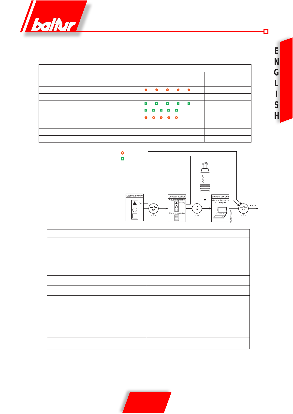
GAS BURNER CONTROL DEVICE GAS LME 22...
Operationalstatus Duringstartup,statusindicationtakesplaceaccordingtothefollowingtable:
indication
Color code table for multicolor signal lamp (LED)
Status Color code Color
Waitingtime«tw»,otherwaitingstates
Ignitionphase,ignitioncontrolled
Operation,ameo.k.
Operation,amenoto.k.
Extraneouslightonburnerstartup
Undervoltage
Fault,alarm
Error code output (refer to «Error code table»)
Interface diagnostics
Legend …. Steady on p Red
¡ Off l Yellow
n Green
Afterlockout.theredfaultsignallampwillremaln
steady on. In thal conditio visual diagnostics of the
cause of fault acccording to the error code table can
beactivatedbypresslngthelockoutresetbutton
for more than 3 seconds. Pressing the reset button
againforatleast3seconds,interfacediagnostics
will be activated
Thefollowlngsequenceactivatesthediagnosticsof
Ihe cause of fault:
¡....................................... Off
l ¡ l ¡ l ¡ l ¡ l
¡....................................................
n ¡ n ¡ n ¡ n ¡ n
n p n p n p n p n
l p l p l p l p l Yellow-red
p.....................................................
p ¡ p ¡ p ¡ p ¡
p p p p p p p p
Flashing yellow
Green
Flashing green
Green-red
Red
Flashing red
Redickerlight
E
N
G
L
I
S
H
Error code table
Red blink code of signal lamp
(LED)
2blinks
l l
3xblinks
l l l
4blinks
l l l l
5blinks
l l l l l
6blinks
l l l l l l
7blinks
l l l l l l l
8xblinks
l l l l l l l l
9blinks
l l l l l l l l l
10blinks
l l l l l l l l l l
Duringthetimethecauseoffaultisdiagnosed,thecontroloutputsaredeactivated
- Burner remains shut down
- Externalfaultindicationremainsdeactivated
- Faultstatussignal«AL»atterminal10,accordingtotheerrorcodetable
Thediagnosticsofthecauseoffaultisquitandtheburnerswitchedonagainbyresettingtheburner
control.Pressthelockoutresetbuttonforabout1second(<3seconds).
«AL» at term. 10 Possible cause
Noestablishmentofameattheendof«TSA»-Faultyorsoiled
On
On
On
On Timeout«LP»-«LP»isweldedinworkingposition
On Free
On
On Free
On Free
Off Wiringerrororinternalerror,outputcontacts,otherfaults
fuelvalves-Faultyorsoiledamedetector-Pooradjustmentof
burner,nofuel-Faultyignitionequipment
«LP» faulty -No or faulty air pressure signal after completion
«t10» - «LP» is welded in normal position
Extraneouslightwhenburnerstartup
Toomanylossesofameduringoperation(limitationof
repetitions)-Faultyorsoiledfuelvalves-Faultyorsoiledame
detector -Poor adjustment of burner
11 / 18
0006081362_200906

METHANE GAS IGNITION AND ADJUSTMENT
E
1) Check that there is water in the boiler and that the gate valves
N
G
L
I
S
H
for the system are open.
2) Check, with complete certainty, that the discharge of combu-
stion products can take place freely (boiler and ue gates
open).
3) Check that the voltage of the electrical line corresponds to
the burner voltage. Electrical connections (motor and main
line) must be prepared for the voltage available. Check that all
electrical connections made on-site are performed correctly as
shown in our wiring diagram. Prevent the second ame from
functioning by disconnecting the 4 pole connector (18) from
the electrical panel (0002935620) for TBG 45P-60P burners;
for TBG 45 60 burners, disconnect the wire from terminal 5 on
the terminal board on the printed circuit supplying coil Y2.
4) Adjust air for the ignition ame :
- for TBG 45P - 60P burners with an electric servomotor, follow
the instructions given in card 0002934711;
- for burner TBG 45 - 60 with manual adjustment, adjust the air
for the second ame on the basis of the instructions given in
the section entitled “Diagram for adjustment of air in TBG 4560 single-stage burner”.
5) Carefully manoeuvre the gas adjustment device valve to open,
for the amount presumed necessary, the rst ame ow adjuster (see the instructions for the two-stage gas valve for the
model installed on the burner). If necessary, of course, open
the safety valve ow adjuster completely if there is one.
6) For three phases burners, with the switch I/O (22) on the burner
panel (see 000293560) at the position “0” and the main switch
on, check, closing the contactor manually, that the motor rotates in the right direction, if necessary swap the two power cables for the motor around to change the direction of rotation.
7) Now switch on the control panel switch (22). The control equi-
pment thus receives voltage and the programmer causes
the burner to switch on as described in the chapter “description of working”. During the preventilation stage you must
check that the air pressure control switch carried out the
exchange (from the closed position without pressure detection it must go to the closed position detecting air pressure).
If the air pressure switch does not detect sufcient pressure
(does not carry out the exchange) the ignition transformer is
not switched on, nor are the gas valves, and so the equipment
is stopped in its “lock-out” mode. On rst switching on repeated “lock outs” may occur due to:
a) the gas piping not being freed of the air sufciently and so
the gas quantity is not enough to provide a stable ame.
b) “lock out” with ame present maybe caused by instability in
the ionisation area, due to an incorrect air/gas ratio. This can
be remedied by varying the quantity of air and/or gas until
the right ratio is found. The same problem may be caused
by incorrect air/gas distribution in the combustion head. This
can be remedied with the combustion head adjustment device by closing or opening further the air passage between
combustion head and gas diffusor.
c) It may happen that the ionisation current is interfered with
by the discharge current of the ignition transformer (the
two currents have a common path on the burner’s “mass”)
so the burner gets locked out due to insufcient ionisation.
This can be remedied by inverting the supply (230V side)
of the ignition transformer (swapping the two wires carrying
voltage to the transformer). This problem may also be caused by an insufcient “ground connection” from the burner’s
casing.
8) With the burner on at minimum you must carry out an immediate
visual check on the extent of and appearance of the ame,
performing the necessary corrections with the gas and air supply regulators (see points 4 and 5). Subsequently a check is
carried out on the quantity of gas supplied, by reading the meter. If necessary the gas supply and the corresponding combustion air can be corrected as previously described (points
4 and 5). Subsequently the combustion is checked with the
special instruments. For a correct air/gas ratio you must nd
a carbon dioxide (CO2) value for the methane that is at least
8 % or O2 = 6% at minimum burner supply up to an optimal
value of 10 % or O2 = 3% for maximum supply. It is essential
to check, with a suitable instrument, that the percentage of
carbon monoxide (CO) present in the fumes does not exceed
the limit set by regulations at the time of installation.”
9) Repeatedly check that the first flame is supplied cor-
rectly. After adjusting operation with the first flame, turn
off the burner, open the main switch and close the electrical circuit commanding inclusion of the second flame:
reinsert the 4 pole connector previously disconnected in the
case of TBG 45P-60P burners; reconnect the wire to terminal 5
on the terminal board on the printed circuit supplying coil Y2 in
the case of TBG 45-60 burners.
10) Open the manual regulator for the gas supply for the second
ame (main ame) to the presumed necessary quantity.
11) Now switch the burner on again, closing the master switch and
that on the control panel. The burner switches on and automatically switches on the second ame (main ame). Carry out an
immediate visual check on the extent of and
appearance of the ame, performing the necessary corrections
with the gas and air supply regulators as indicated in points 4
and 5.
12) Use the adjuster to set the correct ow for the second ame as
required for the specic case. You must not keep the burner
running if the capacity is greater than the maximum permitted
amount for the boiler, or there is a risk it could be damaged.
It is therefore best to stop the burner immediately after the
twometer readings.
13) Subsequently, with the burner at maximum supply required by
the boiler, check the combustion with the special instruments
and if necessary change the adjustment previously carried out
(air and possibly gas) with just the visual check (CO
10 % O2 min =3% - CO max. =
14) The air pressure switch is there to prevent the opening of the
gas valves if the air pressure is not that required. The pressure
switch must therefore be adjusted to intervene to close its con-
0.1%
max. =
2
12 / 18
0006081362_200906
tact when the air pressure in the burner reaches a sufcient
value. The pressure switch connection circuit provides for auto
control so it necessary for the contact to be actually closed
when the fan is stopped (no air pressure in burner). If it is not
the command and control equipment will not go on (the burner
stays stopped). If the air pressure switch does not detect pressure greater than that calibrated, the equipment runs through
its cycle but does not switch on the ignition transformer and
does not open the gas valves and so the burner “locks-out”.
To ensure correct working of the air pressure switch you must,
with burner on and with rst ame only, increase the regulation until it is triggered and immediately “locks-out” the burner.
To release the burner, press the release button and adjust the
pressure switch to a sufcient level to detect the existing air
pressure during the preventilation stage.
15) The control pressure switches for the gas (minimum) are to
prevent the working of the burner when the pressure of the
gas is not as provided for. It is clear from the specic function
of the pressure switches that the control pressure switch for
minimum pressure must make use of the contact that is closed
when the pressure switch detects a pressure greater than that
for which it is regulated. The adjustment of the minimum gas
pressure switch must therefore be carried out when the burner
is started up, in accordance with the pressure that is found at
the time. The triggering (i.e. the opening of the circuit) of any
of the pressure switches when the burner is running (ame on)
cause the burner to stop immediately. On rst switching on of
the burner it is essential to check the correct working of the
pressure switch.
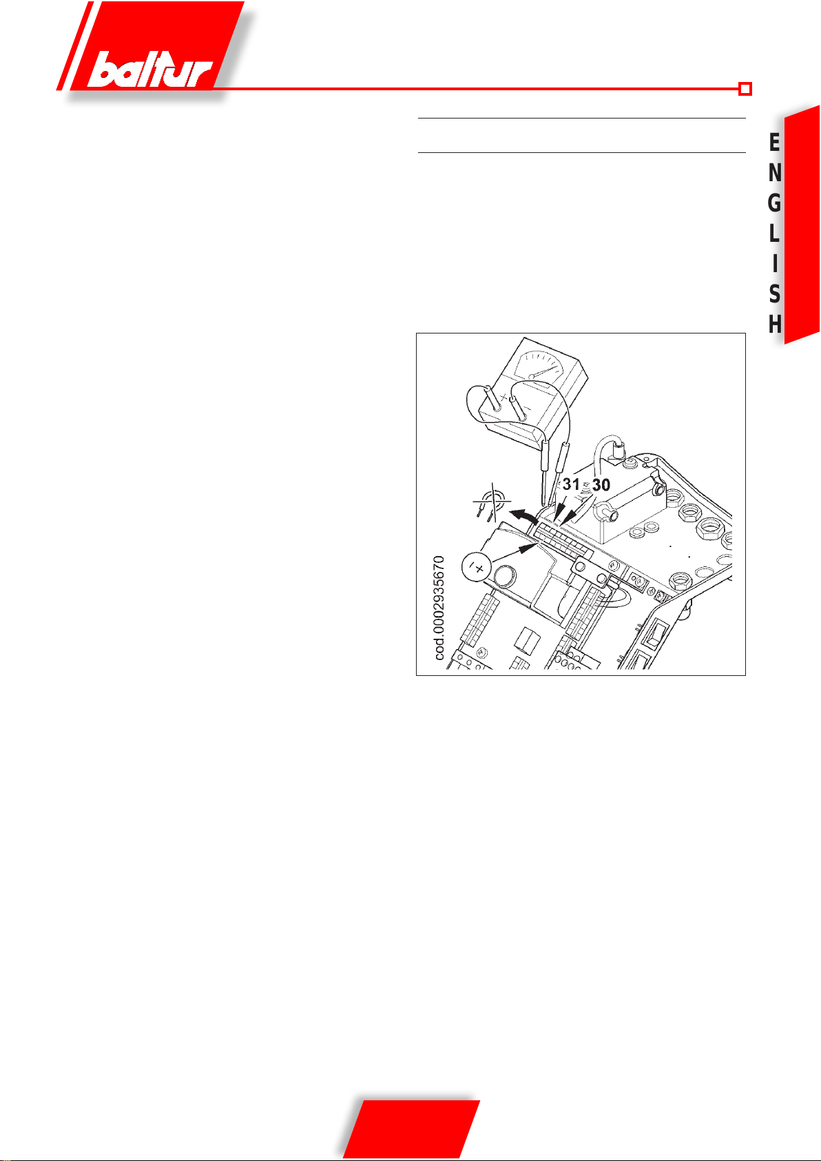
IONISATION CURRENT MEASUREMENT
To measure the ionisation current, remove the jumper
between terminals 30-31 on the printed circuit with the
burner off (see diagram). Connect a microampmeter to the
terminals (with a suitable scale to have the burner restart).
Oncetheamehasappeareditwillbepossibletomeasure
theionisationcurrent,theminimumvalueofwhichtoensure
theworkingoftheequipmentisshowninthespecicwiring
diagram.After makingthe measurement, resetthe jumper
that has been disconnected.
E
N
G
L
I
S
H
16) Check the triggering of the ame detector (ionisation electro-
de) by disconnecting the jumper between terminals 30 and 31
on the printed circuit board and switching on the burner. The
equipment must run through its cycle completely and, three
seconds after the ignition ame has formed, “lock-out”. This
check must also be carried out the burner already on. Disconnecting the 30 and 31 jumper, the equipment must immediately go into its “lock-out” action.
17) Check the proper working of the boiler thermostats or pressu-
re switches (when triggered they must stop the burner).
IMPORTANT. Check that the switch on occurs normally since if
the adjuster is shifted forward, it may happen that
the speed of the delivery air is so high that ignition
is difcult. If this happens, the adjust must be shifted back by degrees until it is in a position in which
ignition occurs normally, and this new position can
be regarded as the nal position. We remind you
that is preferable, in the case of the small ame, to
limit the quantity of air to the least possible needed
for safe ignition, even in the most difcult circumstances.
13 / 18
0006081362_200906
ELECTRODES/IONISATION PROBE ADJUSTMENT DIAGRAM
E
N
G
L
S
H
0002935680
I
Mod. A B C
TBG 45 - 45P 4 5 4
TBG 60P 4 10 -
TBG 60 4 11 4
COMBUSTION HEAD AIR ADJUSTMENT
The combustion head has an adjustment device so that the air
passage between the disk and the combustion head is opened
or closed. You are thus able to obtain, closing the passage, high
pressure upstream of the disk even at low capacity. The high
speed and turbulence of the air provides for its greater penetration
into the fuel and therefore an excellent mixture and ame stability.
It may be necessary to have high air pressure before the disk to
prevent ame uctuations, particularly essential when the burner
works on the combustion chamber that is pressurized and/or at a
high thermal load.
It is clear from the above that the device that closes the air to the
blast-pipe must be set at a position such as to always obtain very
Legend:
1- Ionisation electrode
2- Ignition electrode
3-Deectordisk
4-Mixer
5- Gas outlet pipe
high air pressure behind the disk. It is advisable to adjust in such
a way as to obtain a closure of the air at the combustion head that
will require a signicant opening of the air damper that regulates
the aspiration ow from the burner fan. This must of course be the
case when the burner is working at maximum desired supply.
In practice you have to start the adjustment with the device that
closes the air at the combustion head in an intermediate position,
switching on the burner for approximate adjustment as explained
previously.
When the maximum desired supply has been reached, the
position of the device that closes the air at the combustion head is
corrected, moving it forward and backwards, until the right amount
of air is owing to the supply, with the air damper in signicantly
open.
14 / 18
0006081362_200906
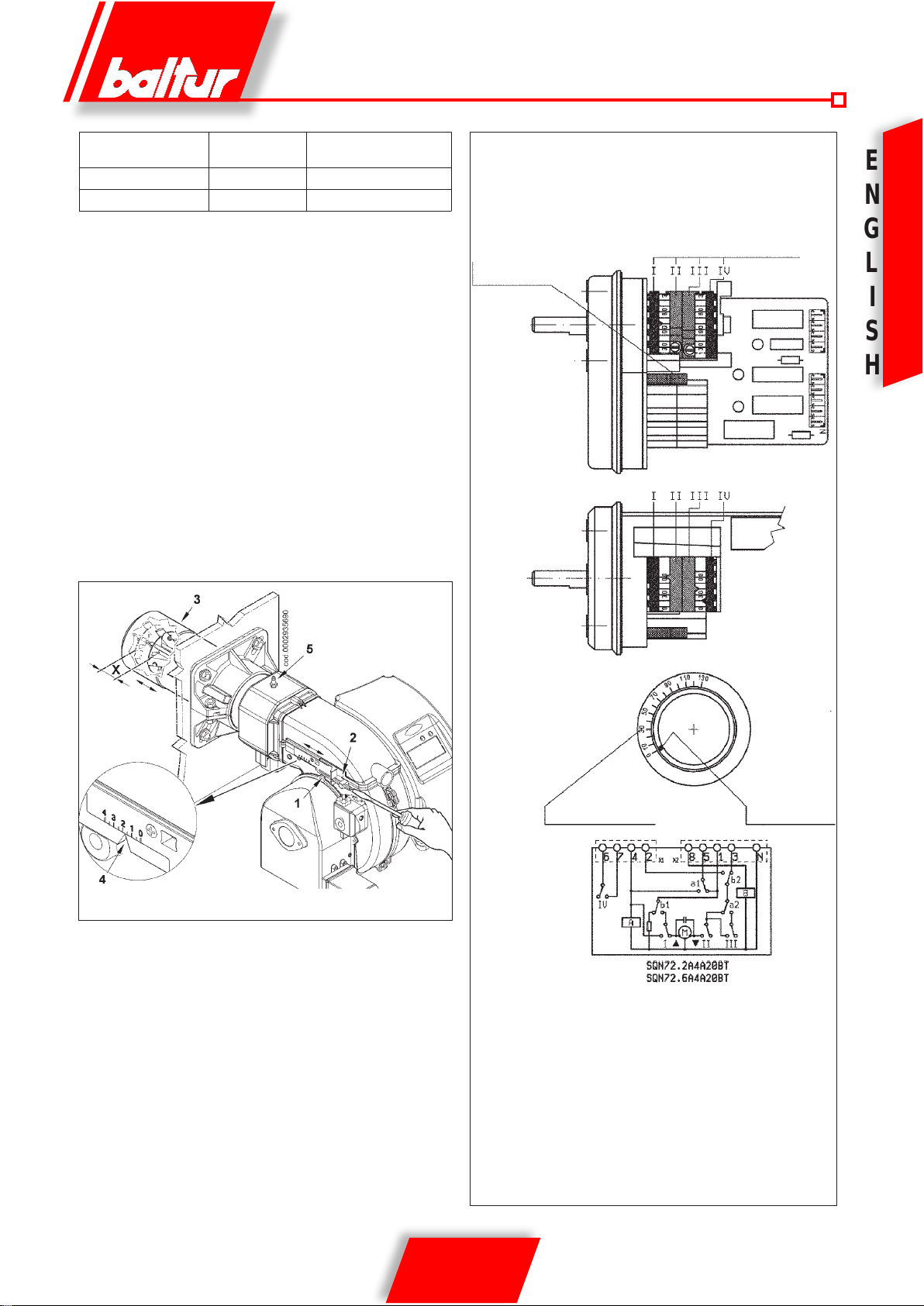
BURNER X
TBG 45 / 45P 3 ÷31 0÷3,2
TBG 60 / 60P 6÷ 34 0÷3,2
X=Distancebetweencombustionheadanddisk;adjustthe
distance X following the indications below:
a)slackenscrew1
b)turnscrew2topositionthecombustionhead3,referring
toindex4.
c)adjustthedistanceXbetweenminimumandmaximum
according the indications in the table.
IMPORTANT The above adjustments are indicative only;
position the combustion head according
to the characteristics of the combustion
chamber
COMBUSTION HEAD ADJUSTMENT SCHEME
Value indicated by
index 4
CAMS REGULATION SERVOMOTOR
SQN72.XA4A20 FOR TBG ...P
INSERTION AND DISINSERTION
LEVER MOTOR CONNECTION
CAMSHAFT
ADJUSTABLE CAMS
E
N
0002934711
G
L
I
S
H
REFERENCE SCALE
I 2nd FLAME AIR ADJUSTING CAM (80°)
II TOTAL AIR CLOSURE (BURNER AT STANDSTILL (0°)
III 1st FLAME AIR ADJUSTING CAM (20°)
IV 2nd FLAME VALVE ACTUATING CAM (40°)
TO MODIFY THE REGULATION OF THE CAMS UTILIZED, OPERATE
THE RESPECTIVE RINGS (I - II - III - IV). THE INDEX OF THE RING
INDICATE ON THE RESPECTIVE REFERENCE SCALE THE ROTATION
ANGLE TAKEN UP FOR EACH CAM.
POSITION
INDICATOR
15 / 18
0006081362_200906
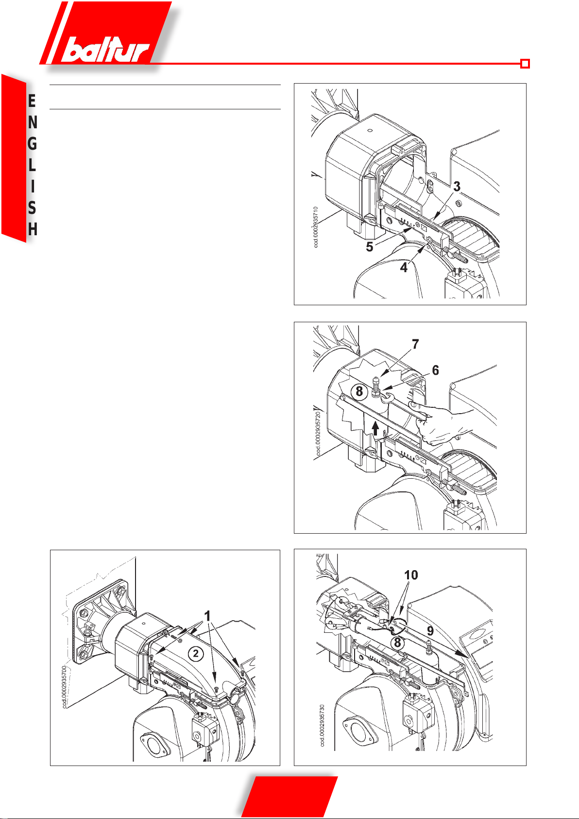
MAINTENANCE
E
Carryout periodicanalysisoftheexhaust combustiongas,
N
checkingtheemissions.
Periodicallyreplacethegaslterwhendirty.
G
Checkthatallthecomponentsofthecombustionheadare
inagoodstate,not deformed by the temperature andfree
L
from impurities or deposits from the installation environment
or by poor combustion and check also the electrodes are
I
workingefciently.
If thecombustion head needs to be cleaned, remove the
S
components following the procedure indicated below:
H
1) Slacken the screws 1 and remove the lid 2 (gure 1).
2) Make sure that mobile plate 3 is held in place by screw 4. This
will permit the mixer unit to be reassembled in the position adjusted previously after completion of maintenance work. Slacken
screw 5, which anchors the unit’s forward movement rod to the
mobile plate (gure 2).
3) Completely unscrew the nut (6) and tighten the screw (7), mo-
ving it forward inside the gas delivery connection (8) far enough
to permit subsequent dismantling of the mixing unit. Slightly raise the gas delivery union (8) out of its housing (gure 3).
4) Completely remove the mixing unit, pulling it out in the direction
shown by arrow 9, after pulling the ignition and ionisation cables 10 out of their electrodes (gure 4).
g-2
Completemaintenanceoperations,proceedwithre-assembly of the combustion head, following the above instructionsinreverseorder,afterhavingcheckedthe correctpo-
sition of the ignition and ionisation electrodes
0002935680).
(see diagram
g-3
g.1
16 / 18
0006081362_200906
g-4
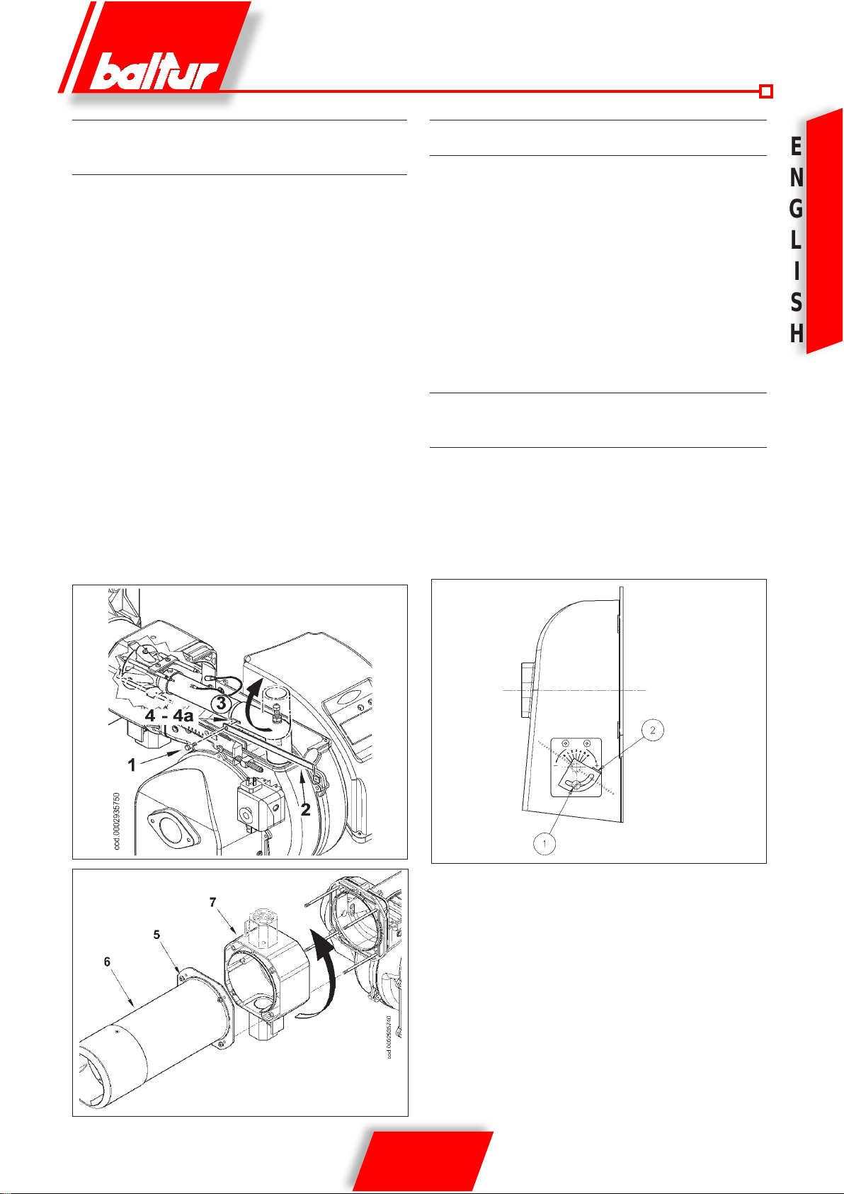
PREPARATION FOR CONNECTION WITH TRAIN TURNED
UPWARD
If you wish to orient the entrance train side upward before applying
the burner to the boiler, proceed as follows.
1) Following the instructions in the section entitled “Maintenance”,
remove the mixer unit and remove the screw (1) connecting the
forward movement rod (2) of the unit with the gas delivery pipe
(3) passing through the slot (4) in the elbow union (gure 1).
2) Turn the elbow union 180° so that the hole in the gas delivery
pipe is aligned with the slot (4a) in the diametrically opposed
position on the union. Connect up the forward movement rod
(2) and the gas delivery pipe (3) with the screw (1) shown in
gure 1.
3) Now remove the 4 nuts (5) in gure 2, dismantle the ame
tube(6) and, after pulling off the lung (7) from its stud bolts, put
it back in position with the threaded connection for anchoring
the gas train turned upward.
4) To complete the operation, anchor the ame tube (6) and the
lung (7) in place with the 4 nuts (5), then put the mixing unit
back in its housing.
You may now install the burner on the boiler with the valve train
layout shown in conguration 9, described in the section on “Assembling the gas train”.
TWO STAGE GAS-FIRED BURNER
It is normally not advisable to connect a burner working on a boiler
for heating water for two-ame working. The burner can also work
for long periods of time with one ame alone. The boiler is insufciently loaded and so come out at too low a temperature (less than
dew point) giving rise to the presence of condensation water in
the ue. When the two-ame burner is installed on a boiler for the
production of hot water for heating, it must be connected in such
a way as to work normally with both ames completely stopping,
without changing to the rst ame, when the preset temperature
has been reached. For this type of working the thermostat for the
second ame is not installed and a direct connection is made (jumper) between the equipment’s terminals.
SINGLE STAGE AIR BURNER TBG 45 - 60
ADJUSTMENT SCHEME
To adjust the angle of opening of the air damper, slacken the screw
(1) and turn the hand wheel (2) to bring the index to the desired
position. Subsequently tighten the screw to lock the damper.
Position 0: air damper fully closed.
Position 6: air damper fully open.
E
N
G
L
I
S
H
Fig. 1
0002934700
Fig. 2
17 / 18
0006081362_200906
E
N
G
L
DETAILS OF PROBLEM POSSIBLE CAUSE SOLUTION
The apparatus goes into “lockout” with the ame (red light on).
Fault restricted to ame control
device
I
S
H
The apparatus goes into “lockout”, gas flows out, but there
is no ame (red light on).Fault
restricted to ignition circuit..
The apparatus goes into “lockout”, gas ows out, but there is
no ame (red light on)
TWO-STAGE GAS BURNERS: TROUBLE-SHOOTING GUIDE
1) Disturbance to ionization current from igni-
tion transformer..
2) Flame sensor (ionization probe) inefcient
.
3) Flame sensor (ionization probe) position
incorrect.
4) Ionization probe or relative earth cable. 4) Check visually and using the instrument.
5) Electrical connection cut-off by ame
sensor.
6) Inefcient draught or fumes passage
blocked..
7) Flame disk or combustion heads dirty or
worn..
8) Equipment fault.. 8) Replace
9) No ionization. 9) If the “earth” of the apparatus is not efcient,
1) Fault in ignition circuit 1) Check the ignition transformer power supply
2) Ignition transformer cable discharges to
earth..
3) Ignition transformer cable disconnected.. 3) Connect..
4) Ignition transformer faulty. 4) Replace.
5) The distance between electrode and earth
is incorrect.
6) Isolator dirty, so electrode discharges to
earth. .
1) air/gas ratio incorrect. 1) Correct the air/gas ratio (there is probably too
2) Gas pipe has not been properly bled of air
(in the case of rst ignition).
3) The gas pressure is insufcient or excessive..
4) Air ow between disk and head too narrow.
1) Invert the ignition transformer power supply
(230V side) and check using an analog microammeter.
2) Replace ame sensor
3) Correct the position of the ame sensor, and
then check its efciency by inserting the analog
micro-ammeter..
5) Restore the connection..
6) Ensure that the boiler fumes passage and
chimney connection are free..
7) Visually check and replace, if necessary.
do not check the ionization current. Check
the efciency of the “earth” at the terminal
concerned of the apparatus and at the “earth”
connection of the electric system..
(230V) and high voltage circuit (electrode
to earth or isolator broken under locking
terminal)..
2) Replace.
5) Position at the correct distance
6) Pulire o sostituire l’isolatore e l’elettrodo.
much air or very little gas)
2) Bleed the gas pipe again, taking great care.
3) Check the maximum gas pressure value at the
time of ignition (use a water pressure gauge,
if possible).
4) Adjust the disk/head opening..
18 / 18
0006081362_200906

Déclaration de conformité
Nous déclarons, sous notre responsabilité, que nos produits portant la marque “CE”
Séries :
Sparkgas…; BTG…; BGN…; TBG...; Minicomist…; Comist…; RiNOx…, BT…;
BTL…; TBL...; GI…; GI…Mist; PYR…; TS…
Description:
brûleurs à air soufé de combustibles liquides, gazeux et mixtes, privés et industriels
respectent les conditions requises minimums imposées par les Directives Européennes:
• 90/396/CEE (Directive Gaz)
• 92/42/CEE (Directive Rendements)
• 89/336/CEE (Directive Compatibilité e.m.)
• 73/23/CEE (Directive Basse Tension)
• 98/37 CEE (Directive Machines)
F
et sont conçus et testés selon les Normes Européennes :
• EN 676 (gaz et mixtes, côté gaz)
• EN 267 (oul et mixtes, côté oul)
- EN 60335-1:2001:A1:2004+A11:2004 +A2:2006
- EN 60335-2-102:2006
- EN 50165:1997:A1:2001
- EN 55014-1:2000 + A1:2001+A2:2002
- EN 55014-2:1997 + A1:2001
- EN 50366:2004 + A1:2006
- EN 61000-3-2:2000 + A2:2005
Organe de Surveillance selon la Directive Gaz 90/396/CEE:
CE0085 - DVGW
Administrateur Délégué:
Dr. Riccardo Fava
SOMMAIRE .............................................................................................................................................................................PAGE
- Recommandations a l’attention del l’utilisateur ......................................................................................................................“ 2
- Caracteristiques techniques ...................................................................................................................................................“ 4
- Application du brûleur a la chaudiere .....................................................................................................................................“ 8
- Branchements electriques .....................................................................................................................................................“ 9
- Description du fonctionnement .............................................................................................................................................“! 10
- Boîtier de commande et de contrôle pour brûleurs à gaz ......................................................................................................“ 11
- Allumage et reglage au gaz methane ....................................................................................................................................“ 12
- Mesure de courant de ionisation ............................................................................................................................................“ 13
- Reglage de l’air sur la tête de combustion .............................................................................................................................“ 14
- Regulation came servomoteur ...............................................................................................................................................“ 15
- Entretient ...............................................................................................................................................................................“ 16
- Prédisposition pour xation de la rampe vers le haut - Bruleur de gas a deux allures -
Schema de reglage air bruleur TBG 55-60 a une allure ........................................................................................................“ 17
- Irrégularité - Cause - Remède ...............................................................................................................................................“ 18
- Schema electrique .................................................................................................................................................................“ 115
R
A
Ç
A
I
S
1 / 18
0006081362_200906

RECOMMANDATIONS A L’ATTENTION DE L’UTILISATEUR POUR UN
USAGE DU BRULEUR EN TOUTE SECURITE INTRODUCTION
L’objectif de ses recommandations est de contribuer, lors de l’utilisation, à la sécurité des composants pour installations de chauffage à
usage privé et production d’eau chaude à usage sanitaire, en indiquant les comportements qu’il est nécessaire ou opportun d’adopter an
d’éviter que leurs caractéristiques de sécurité d’origine soient compromises par d’éventuelles installations incorrectes, des usages inap-
propriés, impropres ou irraisonnables. La diffusion des recommandations gurant dans ce guide a aussi pour but de sensibiliser le public
des «consommateurs» aux problèmes de sécurité à travers un langage nécessairement technique mais facilement accessible. Le fabricant
décline toute responsabilité contractuelle et extra contractuelle en cas de dommages provoqués par des erreurs lors de l’installation ou de
l’usage et, dans tous les cas, par un non-respect des instructions fournies par ce fabricant.
RECOMMANDATIONS GENERALES
• La notice d’instructions est une partie intégrante et essentielle du produit et doit être remise à l’usager. Lire attentivement les recommandations gurant dans la notice car elles fournissent d’importantes indications concernant la sécurité d’installation, d’utilisation et d’entre-
tien. Conserver soigneusement la notice pour toute ultérieure consultation.
• L’installation de l’appareil doit être effectuée conformément aux normes en vigueur, selon les instructions du fabricant et par du personnel
professionnellement qualié. Par personnel qualié on entend du personnel ayant les compétences techniques nécessaires dans le secteur
des composants d’installations de chauffage à usage privé et la production d’eau chaude à usage sanitaire et, plus particulièrement, les
centres de service après-vente agréés par le fabricant. Une mauvaise installation peut provoquer des dommages aux personnes, animaux
ou choses, le fabricant déclinant toute responsabilité.
F
• Après avoir ôter tous les emballages, vérier l’état du contenu. En cas de doute, ne pas utiliser l’appareil et contacter le fournisseur. Les
éléments de l’emballage (cage en bois, clous, agrafes, sachets en plastique, polystyrène expansé, etc.) ne doivent pas être laissés à la
R
portée des enfants dans la mesure où ils constituent des sources potentielles de danger. De plus, pour éviter toute pollution, ils doivent
être déposés dans des lieux prévus à cet effet.
A
• Avant d’effectuer toute opération de nettoyage ou d’entretien, débrancher l’appareil du réseau d’alimentation en intervenant sur l’interrupteur de l’installation et/ou sur les organes de coupures appropriés.
Ç
• En cas de panne et/ou de mauvais fonctionnement de l’appareil, le désactiver et ne tenter aucune action de réparation ou d’intervention
directe. S’adresser exclusivement à du personnel professionnellement qualié. L’éventuelle réparation des produits doit être effectuée
A
par un centre de service après-vente agréé par BALTUR en utilisant exclusivement des pièces détachées d’origine. Le non-respect de
cette recommandation peut compromettre la sécurité de l’appareil. Pour garantir l’efcience de ce dernier et pour que son fonctionnement
I
soit correct, il est indispensable de faire effectuer l’entretien périodique par du personnel professionnellement qualié en respectant les
indications du fabricant.
S
• Si l’appareil doit être vendu ou transféré à un autre propriétaire ou si celui-ci doit déménager et laisser ce dernier, toujours vérier que la
notice accompagne l’appareil an qu’il puisse être consulter par le nouveau propriétaire et/ou par l’installateur.
• Pour tous les appareils avec options ou kit (y compris les électriques) il est nécessaire d’utiliser uniquement des accessoires originaux.
BRULEURS
• Cet appareil doit être uniquement destiné à l’usage pour lequel il a été expressément prévu à sqvoir appliqué à des chaudières, générateurs d’air chaud, fours ou autres foyers similaires, situés dans un lieu à l’abri des agents atmosphériques. Tout autre usage est considéré
comme impropre et donc dangereux.
• Le brûleur doit être installé dans un local adapté avec des ouvertures minimums d’aération, correspondant aux normes en vigueur et sufsantes pour obtenir une combustion parfaite.
• Ne pas obstruer ni réduire la section des grilles d’aspiration d’air du brûleur, il en est de même pour les ouvertures d’aération de la pièce où
est installé un brûleur ou une chaudière, an d’éviter toute situation dangereuse telle que la formation de mélanges toxiques et explosifs.
• Avant de raccorder le brûleur, vérier que les données de la plaquette signalétique correspondent à celles du réseau d’alimentation
(électrique, gaz, oul ou autre combustible).
• Ne pas toucher les parties chaudes du brûleur. Ces dernières, normalement situées à proximité de la amme et de l’éventuel système de
préchauffage du combustible, chauffent durant le fonctionnement et restent chaudes y compris après un arrêt non prolongé du brûleur.
• En cas de décision dénitive de ne plus utiliser le brûleur, il est nécessaire de faire effectuer les interventions suivantes par du personnel
qualié:
a) Couper l’alimentation électrique en débranchant le câble d’alimentation de l’interrupteur général.
b) Fermer l’alimentation du combustible à l’aide de la vanne manuelle de coupure et ôter les volants de commande de leur logement.
c) Rendre inoffensives les parties susceptibles de constituer des sources potentielles de danger.
Recommandations particulières
• Vérier que la personne qui a effectué l’installation du brûleur a xé solidement ce dernier au générateur de chaleur, de façon que la
amme se forme à l’intérieur de la chambre de combustion du générateur.
• Avant de démarrer le brûleur et au moins une fois par an, faire effectuer les interventions suivantes par du personnel qualié :
a) Etalonner le débit du combustible du brûleur selon la puissance requise par le générateur de chaleur.
b) Régler le débit d’air comburant pour obtenir une valeur de rendement de la combustion au moins égale au minimum imposé par les
normes en vigueur.
c) Effectuer le contrôle de la combustion an d’éviter la formation de gaz non brûlés nocifs ou polluants au-delà des limites autorisées par
les normes en vigueur.
d) Vérier le fonctionnement des dispositifs de réglage et de sécurité.
e) Vérier le fonctionnement du conduit d’évacuation des produits de la combustion.
f) A la n des réglages, contrôler que tous les systèmes de blocage mécanique des dispositifs de réglage sont bien serrés.
g) Vérier que les instructions relatives à l’utilisation et l’entretien du brûleur se trouvent dans le local chaudière.
• En cas de blocages répétés du brûleur, ne pas insister avec les procédures de réarmement manuel mais contacter du personnel professionnellement qualié pour remédier à cette situation anormale.
• La conduite et l’entretien doivent être effectués exclusivement par du personnel qualié, dans le respect des dispositions en vigueur.
2 / 18
0006081362_200906

RECOMMANDATIONS A L’ATTENTION DE L’UTILISATEUR POUR UN
USAGE DU BRULEUR EN TOUTE SECURITE INTRODUCTION
ALIMENTATION ELECTRIQUE
• La sécurité électrique de l’appareil est atteinte uniquement lorsque ce dernier est correctement raccordé à une installation de mise à la terre efcace, exécutée comme prévu par les normes de sécurité en vigueur. Cette condition requise de
sécurité est fondamentale. En cas de doute, demander un contrôle soigné de l’installation électrique par du personnel
qualié ; le fabricant n’est pas responsable en cas d’éventuels dommages provoqués par l’absence de mise à la terre de
l’installation.
• Faire vérier par du personnel qualié que l’installation électrique est adaptée à la puissance maximum absorbée par l’appareil, indiquée sur la plaquette signalétique, en vériant plus particulièrement que la section des câbles de l’installation
correspond à la puissance absorbée par l’appareil.
• L’utilisation d’adaptateurs, prises multiples et/ou rallonges n’est pas autorisée pour l’alimentation générale de l’appareil.
• Pour le raccordement au réseau, il est nécessaire d’installer un interrupteur omnipolaire, comme prévu par les normes de
sécurité en vigueur.
• L’alimentation électrique du brûleur doit prévoir le neutre à la terre. En cas de supervision du courant d’ionisation avec
neutre non relié à la terre, il est indispensable de raccorder le circuit RC entre la borne 2 (neutre) et la terre.
• L’utilisation d’un composant quelconque fonctionnant à l’électricité implique l’observation de certaines règles fondamentales, à savoir :
- Ne pas toucher l’appareil avec des parties du corps mouillées ou humides et/ou avec les pieds humides.
- ne pas tirer les câbles électriques.
- ne pas laisser l’appareil exposé à des agents atmosphériques (pluie, soleil, etc.) à moins que cela ait été expressément prévu.
- ne pas permettre que des enfants ou des personnes inexpérimentées utilisent l’appareil.
• Le câble d’alimentation de l’appareil ne doit pas être remplacé par l’usager. En cas de détérioration du câble, éteindre
l’appareil et contacter exclusivement du personnel qualié pour son remplacement.
• En cas de non-utilisation de l’appareil pendant une certaine période, il convient d’éteindre l’interrupteur électrique d’alimentation à tous les composants de l’installation qui utilisent de l’énergie électrique (pompes, brûleur, etc.).
ALIMENTATION AU GAZ, FIOUL OU AUTRES COMBUSTIBLES
Recommandations générales
• L’installation du brûleur doit être effectuée par du personnel professionnellement qualié et conformément aux normes et
dispositions en vigueur car une mauvaise installation peut provoquer des dommages aux personnes, animaux ou choses.
Dans ce cas, le fabricant décline toute responsabilité.
• Avant l’installation, il est conseillé d’effectuer un nettoyage interne soigné de tous les tuyaux d’arrivée du combustible an
d’éliminer les éventuels résidus susceptibles de compromettre le bon fonctionnement du brûleur.
• Lors de la première mise en service de l’appareil, faire effectuer les vérications suivantes par du personnel qualié :
a) le contrôle de l’étanchéité de la partie interne et externe des tuyaux d’arrivée du combustible ;
b) la réglage du débit du combustible en fonction de la puissance requise au brûleur ;
c) le brûleur doit être alimenté par le type de combustible pour lequel il est prédisposé ;
d) la pression d’alimentation du combustible doit être comprise dans les valeurs indiquées sur la plaquette signalétique du
brûleur ;
e) l’installation d’alimentation du combustible doit être dimensionnée pour le débit nécessaire au brûleur et dotée de tous les
dispositifs de sécurité et de contrôle prescrits par les normes en vigueur.
• En cas de non-utilisation du brûleur pendant une certaine période, fermer le robinet ou les robinets d’alimentation du
combustible.
Recommandations particulières pour l’utilisation du gaz
• Faire vérier par du personnel professionnellement qualié :
a) que la ligne d’arrivée et la rampe sont conformes aux normes et prescriptions en vigueur.
b) que tous les raccords de gaz sont étanches.
• Ne pas utiliser les tuyaux du gaz comme mise à la terre d’appareils électriques.
• Ne pas laisser l’appareil inutilement activé lorsqu’il n’est pas utilisé et toujours fermer le robinet de gaz.
• En cas d’absence prolongé de l’usager de l’appareil, fermer le robinet principal d’arrivée du gaz au brûleur.
• En cas d’odeur de gaz :
a) ne pas actionner d’interrupteurs électriques, ne pas utiliser le téléphone et tout autre objet susceptible de provoquer
des étincelles ;
b) ouvrir immédiatement les portes et fenêtres pour créer un courant d’air pour purier la pièce ;
c) fermer les robinets de gaz ;
d) demander l’intervention d’un personnel professionnellement qualié.
• Ne pas obstruer les ouvertures d’aération de la pièce où est installé un appareil à gaz an d’éviter toute situation dange-
reuse telle que la formation de mélanges toxiques et explosifs.
F
R
A
Ç
A
I
S
CHEMINEES POUR CHAUDIERES A HAUT RENDEMENT ET SIMILAIRES
Il convient de préciser que les chaudières à haut rendement et similaires évacuent dans la cheminée les produits de la
combustion (fumées) à une température relativement basse. Dans cette condition, les cheminées traditionnelles, dimensionnées de façon habituelle (section et isolation thermique) peuvent ne pas être adaptées pour fonctionner correctement
car le refroidissement sensible que les produits de la combustion subissent pour les parcourir permet, très probablement,
une diminution de la température même en dessous du point de condensation. Dans une cheminée qui fonctionne au régime de condensation, on constate la présence de suie à l’embouchure dans l’atmosphère lorsque l’on brûle du oul ou du
oul lourd et la présence d’eau de condensation le long de la cheminée lorsque l’on brûle du gaz (méthane, GPL, etc.). On
peut donc en déduire que les cheminées raccordées à des chaudières à haut rendement et similaires doivent être dimensionnées (section et isolation thermique) pour l’usage spécique an d’éviter l’inconvénient décrit précédemment.
3 / 18
0006081362_200906
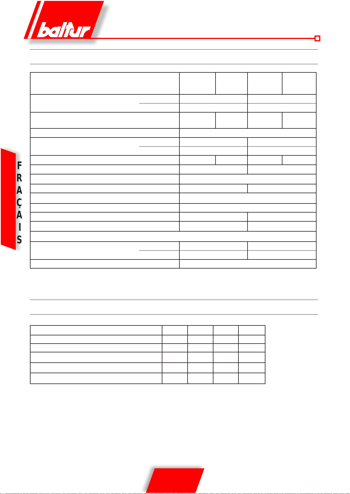
CARACTERISTIQUES TECHNIQUES
CARACTERISTIQUES TECHNIQUES
THERMIC CAPACITY
FONCTIONNEMENT Une allure Deux allures Une allure Deux allures
EMISIÓN NOx mg/kWh < 80 (Classe III secondo EN 676)
MOTEUR
PUISSANCE ELECTRIQUE ABSORBEE* kW 0,67 0,69 0,93 0,96
F
fusible de línea A / 400 V - - 4
TRANSFORMATEUR D’ALLUMAGE
R
TENSION 1N ~ 230 V ±10%- 50 Hz 3N ~ 400 V ±10%- 50 Hz
A
DEGRE DE PROTECTION IP 44
Ç
DETECTION FLAMME SONDE DE IONISATION
A
NIVEAU DE BRUIT** dBA 73 75
POIDS kg 40 42
I
Gaz naturel (G 20)
S
DEBIT
PRESION MAX mbar 360
MAX kW 450 600
MIN kW 100 120
kW 0,50 0,75
r.p.m. 2730 2800
MAX m³n/h 45,3 60,3
MIN m³n/h 10,1 12,1
TBG 45 TBG 45P TBG 60 TBG 60P
26 kV - 40 mA - 230/240 V - 50/60 Hz
*) Absorption totale en phase de départ, avec transformateur d’allumage enclenché.
**) Pression sonore mesurée dans le laboratoire du fabricant, avec brûleur fonctionnant sur une chaudière d’essai à la puissance thermique nominale maximale.
ACCESSOIRES STANDARD
TBG 45 TBG 45P TBG 60 TBG 60P
BRIDE DE FIXATION BRULEUR 2 2 2 2
JOINT ISOLANT 1 1 1 1
GOUJONS N° 4 M 12 N° 4 M 12 N° 4 M 12 N° 4 M 12
ECROUS N° 4 M 12 N° 4 M 12 N° 4 M 12 N° 4 M 12
RONDELLES PLATES N° 4 Ø 12 N° 4 Ø 12 N° 4 Ø 12 N° 4 Ø 12
4 / 18
0006081362_200906
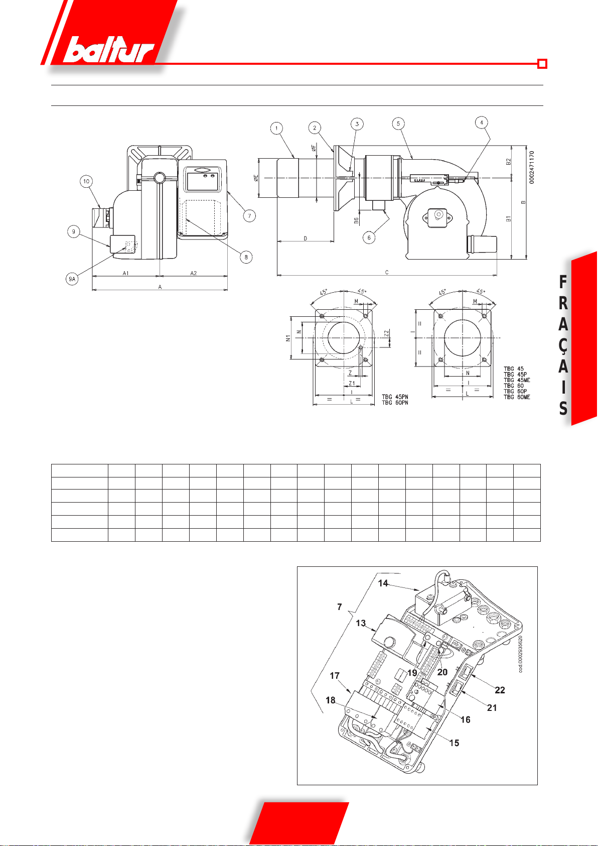
DIMENSION DE ENCOMBREMENT
F
1) Tête de combustion
2) Joint
3) Bride de xation brûleur
4) Dispositif de réglage tête
5) Couvercle
6) Bride de xation rampe à gaz
7) Tableau électrique
8) Moteur
9) Servomoteur de réglage de l’air
9a) Réglage manuel de l’air (TGB 45/60)
10) Pressostat d’air
MOD. A A1 A2 B B1 B6 C D D E F I L L M N
min max Ø Ø min max
TBG 45 550 270 280 435 325 160 880 140 300 137 133 215 200 245 M12 145
TBG 45P 550 270 280 435 325 160 920 140 300 137 133 215 200 245 M12 145
TBG 60 550 270 280 455 325 160 880 140 300 156 152 260 225 300 M12 160
TBG 60P 550 270 280 455 325 160 920 140 300 156 152 260 225 300 M12 160
13) Boîtier de commande et de contrôle
R
A
Ç
A
I
S
14) Transformateur d’allumage
15) Contacteur moteur (alimentation triphasée)
16) Relais thermique (alimentation triphasée)
17) Fiche 7 pôles
18) Fiche 4 pôles
19) Led brûleur allumé
20) Led brûleur bloqué
21) Bouton de déblocage
22) Interrupteur marche/arrêt
5 / 18
0006081362_200906
DOMAINE DE FUNCTIONEMENT TBG 45 / 60 A UNE ALLURE
F
R
A
Ç
A
I
S
DOMAINE DE FUNCTIONEMENT TBG 45P / 60P A DEUX ALLURES
Les domaines de fonctionnement sont obtenus sur des chaudières d’essai répondant à la norme EN676 et sont indicatifs
en ce qui concerne les accouplements brûleur-chaudière.
Pour un fonctionnement correct du brûleur, les dimensions de la chambre de combustion doivent correspondre à la norme
en vigueur ; dans le cas contraire, il est nécessaire de contacter les fabricants.
6 / 18
0006081362_200906
 Loading...