

baltur TBG 85 ME, TBG 210 ME, TBG 150 ME, TBG 120 ME User Instruction Manual
SP
user instructions manualUKManual de instrucciones
para el uso.
FR
Manuel d'instructions
pour l'utilisation.
TBG 85 ME
TBG 120 ME
TBG 150 ME
TBG 210 ME
TR
Kullanım talimatları
kılavuzu.
РУС
Руководство инструкции
по эксплуатации.
中文
使用说明
- TWO-STAGE PROGRESSIVE / MODULATING GAS BURNERS WITH
ELECTRONIC CAM BT 3..
- QUEMADORES DE GAS DE DOS ETAPAS PROGRESIVAS / MODULANTES CON LEVA ELECTRÓNICA BT 3..
- BRULEURS DE GAZ A DEUX ALLURES PROGRESSIVES / MODULANTES AVEC CAME ELECTRONIQUE BT 3..
- BT 3.. ELEKTRONİK KAMLI İLERLEMELİ / MODÜLASYON İKİ FAZLI
GAZ BRÜLÖRLERİ
- ДВУХСТУПЕНЧАТЫЕ ГАЗОВЫЕ ПРОГРЕССИВНЫЕ / МОДУЛЯЦИОННЫЕ ГОРЕЛКИ С ЭЛЕКТРОННЫМ КУЛАЧКОМ BT 3..
二段渐进式/电子凸轮”BT 3“调控式燃气燃烧器
ORIGINAL INSTRUCTIONS (IT)
I
NSTRUCCIONES ORIGINALES (IT
I
STRUCTIONS ORIGINALES (IT)
ORİJİNAL KULLANIM KILAVUZU (IT)
ОРИГИНАЛЬНЫЕ ИНСТРУКЦИИ
(
ПЕРЕВОД С ИТАЛЬЯНСКОГО ЯЗЫКА
正版说明书。(IT)
)
)
0006081531_201203

- Before using the burner for the first time please carefully read the chapter “WARNING NOTES FOR THE USER:
BALTUR S.p.A.
Via Ferrarese 10 - 44042 CENTO (Ferrara) ITALIA
Tel. 051.684.37.11 Fax 051.685.75.27/28
(International Tel. ++39.051.684.37.11 - Fax ++39.051.683.06.86)
http://www.baltur.it - http://www.baltur.com - E-MAIL info@baltur.it
HOW TO USE THE BURNER SAFELY” in this instruction manual, which is an integral and essential part of the product.
- Read carefully the instructions before starting the burner and servicing it.
- The works on the burner and on the system should be carried out only by qualified personnel.
- The system power supply must be disconnected before starting working.
- If the works are not carried out correctly it is possible to cause dangerous accidents.
Declaration of Conformity
We declare that our products
BPM...; BGN…; BT…; BTG…; BTL…; TBML...; Comist…;
GI…; GI…Mist; Minicomist…; PYR…; RiNOx…; Spark...;
Sparkgas...; TBG...;TBL...; TBML ...; TS…; IBR...; IB...
(Variant: … LX, for low NOx emissions)
Description:
forced air burners of liquid, gaseous and mixed fuels for residential and
industrial use meet the minimum requirements of the European Directives:
2009/142/CE ..............................................(D.A.G.)
2004/108/CE ...............................................(C.E.M.)
2006/95/CE .................................................(D.B.T.)
2006/42/CE ................................................(D.M.)
and conform to European Standards:
ENGLISH
UNI EN 676:2008 (gas and combination, gas side)
UNI EN 267:2002 (diesel and combination, diesel side)
These products are therefore marked:
0085
Dr. Riccardo Fava
18/11/2010
!
WARNINGS / NOTES
TECHNICAL SPECIFICATIONS ....................................................................................................................................................................................... 4
CONNECTING THE BURNER TO THE BOILER
GAS SUPPLY LINE
ELECTRICAL CONNECTIONS
DESCRIPTION OF TWO-STAGE PROGRESSIVE OPERATION
NATURAL GAS IGNITION AND ADJUSTMENT
IONISATION CURRENT MEASUREMENT
ADJUSTING THE AIR ON THE COMBUSTION HEAD
MAINTENANCE
HOW TO FIND THE CAUSES OF IMPROPER OPERATION HOW TO RECTIFY THEM
ELECTRIC DIAGRAM
.......................................................................................................................................................................................................... 8
........................................................................................................................................................................................ 9
......................................................................................................................................................................12
............................................................................................................................................................................................................... 15
...................................................................................................................................................................................................... 17
i
INFORMATION
............................................................................................................................................................. 7
................................................................................................................................... 10
..............................................................................................................................................................11
................................................................................................................................................... 14
Managing Director / CEO
I
DANGER / CAUTION
.............................................................................................. 16
1 / 20
0006081531_201203

I
accordance with current regulations and in any case suf cient to ensure
ventilation openings for the room where a burner or a boiler is installed
• If it is decided not to use the burner any more, the following actions must
• Check that the person who carried out the installation of the burner xed
b) Adjust the combustion air ow to obtain combustion yield of at least
• If the burner repeatedly stops in lock-out, do not keep trying to manually
WARNING NOTES FOR THE USER HOW TO USE THE BURNER SAFELY
FOREWORD
These warning notes are aimed at ensuring the safe use of the components of heating systems for civil use and the production of hot water.
They indicate how to act to avoid the essential safety of the components
being compromised by incorrect or erroneous installation and by improper
or unreasonable use. The warning notes provided in this guide also seek
to make the consumer more aware of safety problems in general, using
necessarily technical but easily understood language. The manufacturer
is not liable contractually or extra contractually for any damage caused
by errors in installation and in use, or where there has been any failure to
follow the manufacturer’s instructions.
GENERAL WARNING NOTES
• The instruction booklet is an integral and essential part of the product
and must be given to the user. Carefully read the warnings in the booklet as they contain important information regarding safe installation,
use and maintenance. Keep the booklet to hand for consultation when
needed.
• Equipment must be installed in accordance with current regulations,
with the manufacturer’s instructions and by quali ed technicians. By
the term ‘quali ed technicians’ is meant persons that are competent in
the eld of heating components for civil use and for the production of
ENGLISH
hot water and, in particular, assistance centres authorised by the manufacturer. Incorrect installation may cause damage or injury to persons,
animals or things. The manufacturer will not in such cases be liable.
• After removing all the packaging make sure the contents are complete
and intact. If in doubt do not use the equipment and return it to the
supplier. The packaging materials (wooden crates, nails, staples, plastic
bags, expanded polystyrene, etc.) must not be left within reach of children as they may be dangerous to them. They should also be collected
and disposed on in suitably prepared places so that they do no pollute
the environment.
• Before carrying out any cleaning or maintenance, switch off the equipment at the mains supply, using the system’s switch or shut-off systems.
• If there is any fault or if the equipment is not working properly, de-activate the equipment and do not attempt to repair it or tamper with it
directly. In such case get in touch with only quali ed technicians. Any
product repairs must only be carried out by BALTUR authorised assistance centres using only original spare parts. Failure to act as above
may jeopardise the safety of the equipment. To ensure the ef ciency
and correct working of the equipment, it is essential to have periodic
maintenance carried out by quali ed technicians following the manufacturer’s instructions.
• If the equipment is sold or transferred to another owner or if the owner
moves and leaves the equipment, make sure that the booklet always
goes with the equipment so it can be consulted by the new owner and/
or installer.
• For all equipment with optionals or kits (including electrical), only original accessories must be used.
BURNERS
• This equipment must be used only for its expressly stated use: applied
to boilers, hot air boilers, ovens or other similar equipment and not
exposed to atmospheric agents. Any other use must be regarded as
improper use and hence dangerous.
• The burner must be installed in a suitable room that has ventilation in
correct combustion
• Do not obstruct or reduce the size of the burner’ air intake grills or the
or dangerous mixtures of toxic and explosive gases may form.
• Before connecting the burner check that the details on the plate correspond to those of the utility supplies (electricity, gas, light oil or other
fuel).
• Do not touch hot parts of the burner. These, normally in the areas near
to the ame and any fuel pre-heating system, become hot when the
equipment is working and stay hot for some time after the burner has
stopped.
be performed by quali ed technicians:
a) Switch off the electrical supply by disconnecting the power cable from
the master switch.
b) Cut off the fuel supply using the shut-off valve and remove the control
wheels from their position.
c) Render harmless any potentially dangerous parts.
Special warning notes
it securely to the heat generator so that the ame is generated inside
the combustion chamber of the generator itself.
• Before starting up the burner, and at least once a year, have quali ed
technicians perform the following operations:
a) Set the burner fuel capacity to the power required by the heat ge-
nerator.
the minimum set by current regulations.
c) Carry out a check on combustion to ensure the production of no-
xious or polluting unburnt gases does not exceed limits permitted
by current regulations.
d) Check the adjustment and safety devices are working properly.
e) Check the ef ciency of the combustion products exhaust duct.
f) Check at the end of the adjustments that all the adjustment devices
mechanical securing systems are properly tightened.
g) Make sure that the use and maintenance manual for the burner is
in the boiler room.
reset but call a quali ed technicians to sort out the problem.
• The running and maintenance of the equipment must only be carried
out by quali ed technicians, in compliance with current regulations.
2 / 20
0006081531_201203

equipment or dangerous situations may arise with the build up of toxic
It should be pointed out that high ef ciency boilers and similar discharge
In the above situation, traditional ues (in terms of their diameter and heat
insulation) may be suitable because the signi cant cooling of the combustion
products in these permits temperatures to fall even below the condensation
point. In a ue that works with condensation there is soot at the point the
exhaust reaches the atmosphere when burning light oil or heavy oil or the
presence of condensate water along the ue itself when gas is being burnt
(methane, LPG, etc.). Flues connected to high ef ciency boilers and similar
must therefore be of a size (section and heat insulation) for the speci c use
I WARNING NOTES FOR THE USER HOW TO USE THE BURNER SAFELY
ELECTRICAL SUPPLY
• The equipment is electrically safe only when it is correctly connected to an
ef cient ground connection carried out in accordance with current safety
regulations. It is necessary to check this essential safety requirement.
If in doubt, call for a careful electrical check by a quali ed technicians,
since the manufacturer will not be liable for any damage caused by a
poor ground connection.
• Have quali ed technicians check that the wiring is suitable for the
maximum power absorption of the equipment, as indicated in the technical
plate, making sure in particular that the diameter of cables is suf cient
for the equipment’s power absorption.
• Adapters, multiple plugs and extension cables may not be used for the
equipment’s power supply.
• An ominpolar switch in accordance with current safety regulations is
required for the mains supply connection.
• The electrical supply to the burner must have neutral to ground
connection. If the ionisation current has control with neutral not to ground
it is essential to make a connection between terminal 2 (neutral) and the
ground for the RC circuit.
• The use of any components that use electricity means that certain
fundamental rules have to followed, including the following:
- do not touch the equipment with parts of the body that are wet or damp
or with damp feet
- do not pull on electrical cables
- do not leave the equipment exposed to atmospheric agents (such as
rain or sun etc.) unless there is express provision for this.
- do not allow the equipment to be used by children or inexpert
persons.
• The power supply cable for the equipment not must be replaced by the
user. If the cable gets damaged, switch off the equipment, and call only
on quali ed technicians for its replacement.
• If you decide not to use the equipment for a while it is advisable to switch
off the electrical power supply to all components in the system that use
electricity (pumps, burner, etc.).
GAS, LIGHT OIL, OR OTHER FUEL SUPPLIES
General warning notes
• Installation of the burner must be carried out by quali ed technicians
and in compliance with current law and regulations, since incorrect
installation may cause damage to person, animals or things, for which
damage the manufacturer shall not can be held responsible.
• Before installation it is advisable to carry out careful internal cleaning
of all tubing for the fuel feed system to remove any residues that could
jeopardise the proper working of the burner.
• For rst start up of the equipment have quali ed technicians carry out
the following checks:
• If you decide not to use the burner for a while, close the tap or taps that
supply the fuel.
Special warning notes when using gas
• Have quali ed technicians check the following:
a) that the feed line and the train comply with current law and
regulations.
b) that all the gas connections are properly sealed.
• Do not use the gas pipes to ground electrical equipment.
• Do not leave the equipment on when it is not in use and always close
the gas tap.
• If the user of is away for some time, close the main gas feed tap to the
burner.
• If you smell gas:
a) do not use any electrical switches, the telephone or any other object
that could produce a spark;
b) immediately open doors and windows to create a current of air that
will purify the room;
c) close the gas taps;
d) ask for the help of quali ed technicians.
• Do not block ventilation openings in the room where there is gas
and explosive mixtures.
FLUES FOR HIGH EFFICIENCY BOILERS AND SIMILAR
combustion products (fumes) at relatively low temperatures into the ue.
to avoid such problems as those described above.
ENGLISH
3 / 20
0006081531_201203
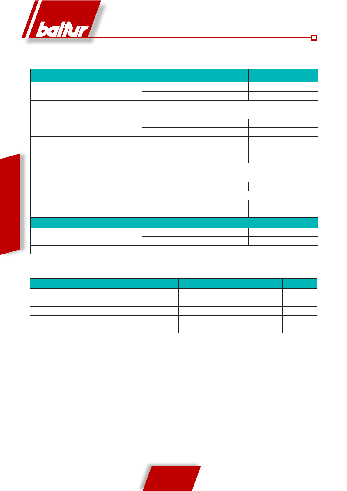
TECHNICAL SPECIFICATIONS
TBG 85ME TBG 120ME TBG 150ME TBG 210ME
HEATING CAPACITY
OPERATION Two-stage progressive / modulating burner
NOx EMISSIONS mg/kWh < 120 (Class II EN 676)
MOTOR
ABSORBED ELECTRICAL POWER* kW 1.20 1.60 2.40 3.2
LINE FUSE A 400 V 6 10 10 16
IGNITION TRANSFORMER 26 kV - 40 mA – 230 V / 50 Hz
VOLTAGE 3N ~ 400 V ±10%- 50 Hz
PROTECTION RATING IP 40
FLAME DETECTOR IONISATION PROBE
NOISE** dBA 73 75.5 79 85
WEIGHT kg 78 87 91 94
ENGLISH
NATURAL GAS (G 20)
FLOW RATE
PRESSURE MAX mbar 500
*) Total absorption at start with ignition transformer on.
**) Noise levels measured in the laboratory of the manufacturer with burner running on test boiler, at maximum rated heating capacity.
MAX kW 850 1200 1500 2100
MIN kW 170 240 300 400
kW 1.1 1.5 2.2 3
r.p.m. 2800 2800 2800 2800
MAX m³n/h 85.5 120.7 150.9 211.2
MIN m³n/h 17 24.1 30.2 40.3
STANDARD ACCESSORIES TBG 85ME TBG 120ME TBG 150ME TBG 210ME
BURNER COUPLING FLANGE 2 2 2 2
INSULATING GASKET 1 1 1 1
STUD BOLTS No. 4 M 12 No. 4 M 12 No. 4 M 12 No. 4 M 12
HEXAGONAL NUTS No. 4 M 12 No. 4 M 12 No. 4 M 12 No. 4 M 12
FLAT WASHERS/ No. 4 Ø 12 No. 4 Ø 12 No. 4 Ø 12 No. 4 Ø 12
TECHNICAL AND FUNCTIONAL SPECIFICATIONS
• Two-stage progressive / modulating output operation.
• Gas adjustment using the butterfly valve controlled by the step
servomotor electronically controlled.
• Combustion head with partial recycling of exhaust gases at low
NOx emissions (class II).
• High fan output, low electrical absorption, low noise.
• Ambidextrous hinge opening for easy access to the combustion
head when burner is installed.
• Airflow adjustment with linear opening shutter driven by a step
servomotor electronically controlled.
• Closing of air shutter in pause.
• Control panel prepared for connection by plugs/sockets
(supplied) with 4 and 7 poles.
• Control panel with protection rating IP55.
• Sliding coupling flange to the generator, to adapt the
protuberance of the head to various types of heating generators.
• High modulation ratio 1:5.
• Gas train exit possibility at the top or at the bottom.
4 / 20
0006081531_201203
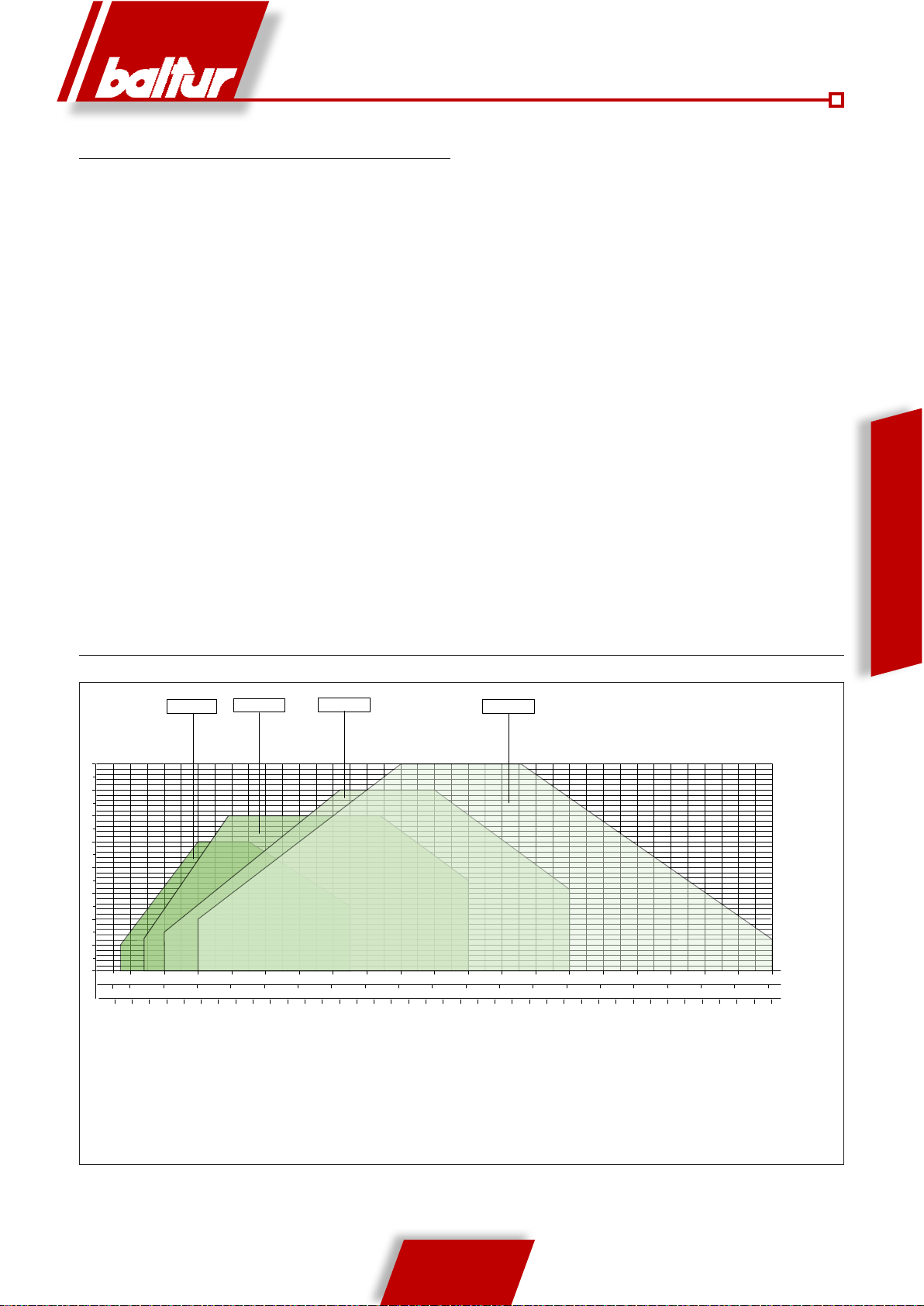
2
4
6
8
0
10
12
14
mbar
15015200 300 400 500 600 700 800 900 1000 1100
20 30 40 50 60 70 80 90
100 110
6 8 10 12 14 16 18 20 22 24 26 28 30 32 34 36 38 40 42 44
m
n³/h(Metano)
m
n³/h(G.P.L.)
kW
1200 1300
120 130
46 48 50
1400 1500 1600
16
140 150 160
52 54 56 58 60 62
1700 1800 1900
2000
170 180 190
200
64 66 68 70 72 74 76 78
2100
210
80 82
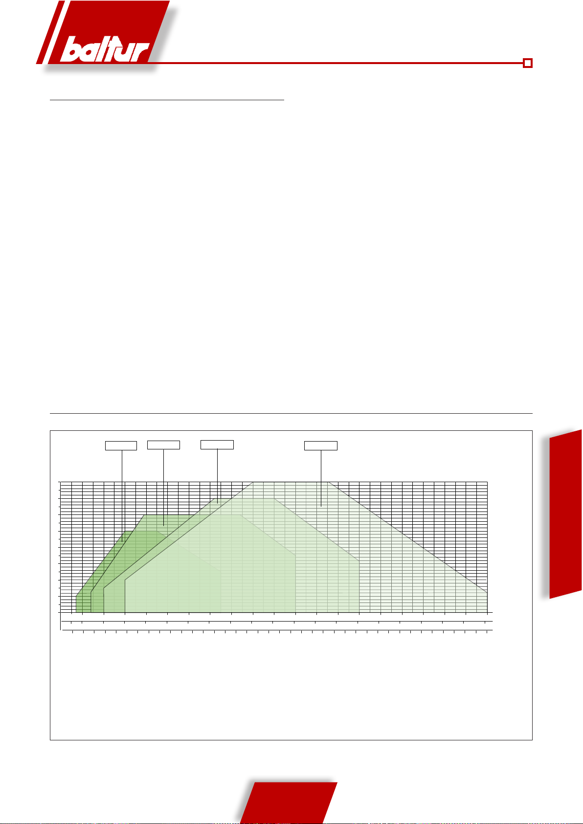
TBG 85ME
TBG 120ME TBG 150ME
TBG 210ME
MANUFACTURING CHARACTERISTICS
The burner consists of the following parts:
• Combustion air intake with insert in soundproofing material
designed to obtain optimum linear air shutter opening.
• Control panel complete with operation mimic panel and indicator
lights.
• Electronic command and control systems according to EN298,
with microprocessor with integrated valve tightness control and
eBus connection ability.
• Display showing the operating sequence and error code.
• Flame detection by ionisation electrode.
• Gas train complete with security valve and electromagnetic
actuator, minimum pressure switch, pressure regulator and
gas filter.
• Burner/train intelligent connectors (error proof).
ENGLISH
OPERATING RANGE
The operating ranges are obtained from test boilers corresponding
to the standard EN676 and are indicative of the burner-boiler
combination. For correct burner operation the size of the
combustion chamber must correspond to current regulations; if
not the manufacturers must be consulted.
0006081531_201203
5 / 20
0002922800
N° 0002471120
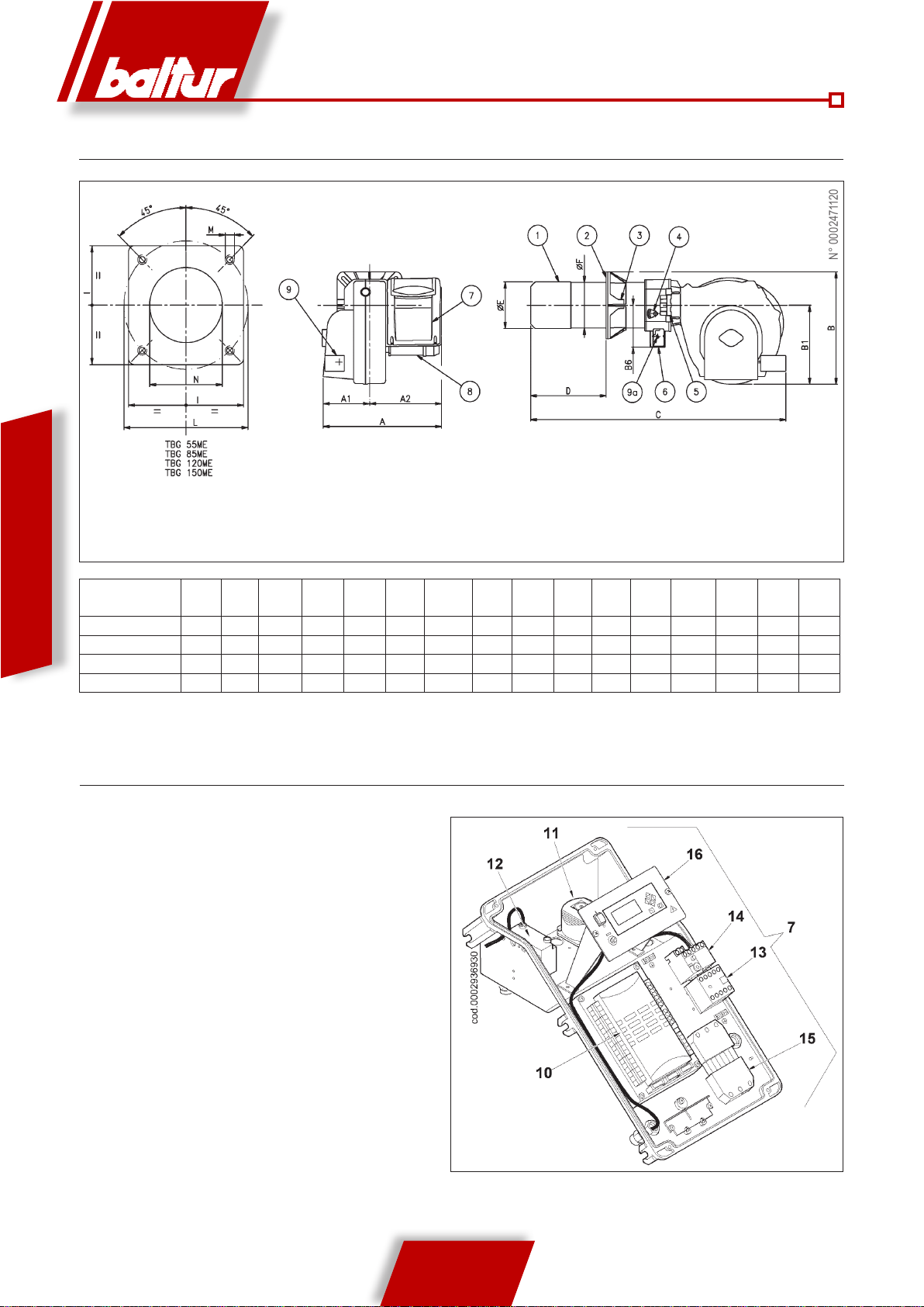
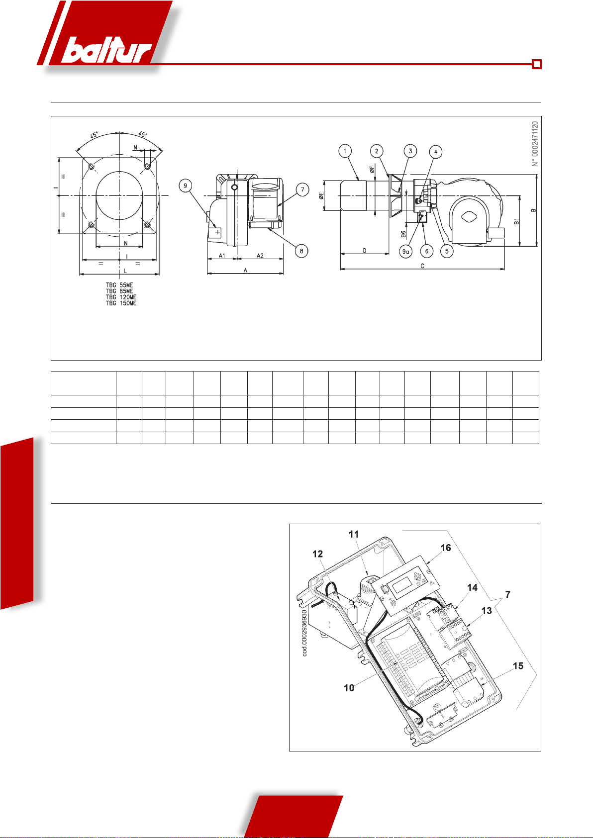
OVERALL DIMENSIONS
ENGLISH
MOD. G A1 A2 B B1 B6 C
TBG 85ME 610 240 370 520 380 200 1265 175 400 180 178 280 250 325 M12 190
TBG 120ME 610 240 370 540 380 200 1265 200 450 224 219 320 280 370 M12 235
TBG 150ME 610 240 370 540 380 200 1265 200 450 240 219 320 280 370 M12 250
TBG 210ME 610 240 370 540 380 200 1315 200 450 250 219 320 280 370 M12 255
ELECTRICAL PANEL COMPONENTS
10) Equipment
11) Air pressure switch
12) Ignition transformer
13) Motor contactor
1) Combustion head
2) Gasket
3) Burner coupling ange
4) Combustion head adjustment device
5) Hinge
6) Gas train coupling ange
7) Electrical panel
8) Motor
9) Air adjustment servomotor
9a) Gas adjustment servomotor
D
MINDMAX
E F E
L
MINLMAX
M H
14) Thermal Relay
15) 7 pole plug
16) Mimic panel
6 / 20
0006081531_201203
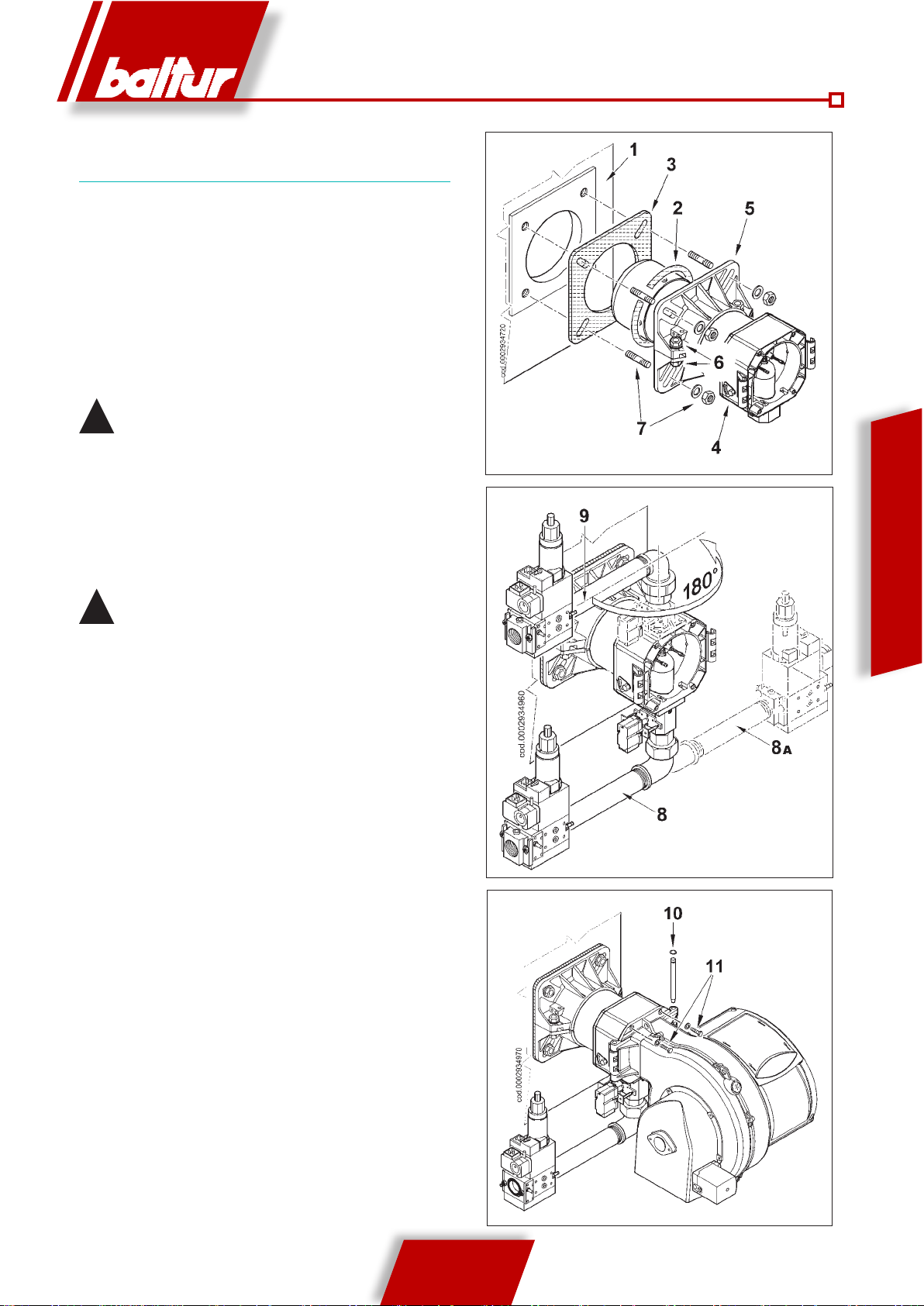
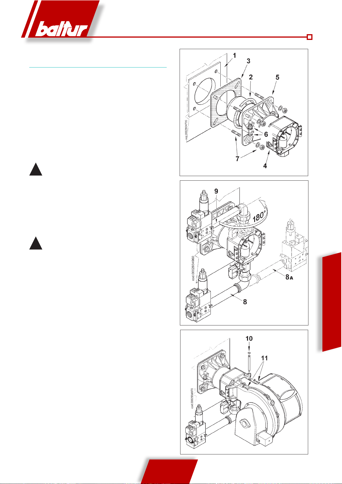
CONNECTING THE BURNER TO THE
BOILER
ASSEMBLING THE HEAD UNIT
A) Adjust the position of the coupling flange 5 by
loosening the screws 6 so that the combustion
head penetrates into the furnace to the extent
recommended by the generator manufacturer.
B) Position the insulating gasket 3 on the sleeve
inserting cord 2 between flange and gasket.
C) Fasten the Head unit 4 to the boiler 1 by means of
the stud bolts, washers and the nuts provided 7.
Completely seal the gap between the burner sleeve and
!
the hole in the refractory material inside the boiler door
with suitable material.
ASSEMBLING THE GAS TRAIN
There are different ways of assembling the valve train,
8, 8a and 9 as shown in the drawing. Choose the most
rational position for the set-up of the boiler room and
the position in which the gas pipeline arrives.
In case of very large valves, e.g. DN65 or DN80, make
!
sure there is a suitable support to prevent excessive
stress on the gas train fitting.
ENGLISH
ASSEMBLING THE VENTILATING UNIT
A) Position the half-hinge on the burner scroll in line
with those on the head unit.
B) Insert the hinge pin 10 in the position considered
most suitable.
C) Connect the cables (ignition and ionisation) to the
corresponding electrodes, close the hinge, locking
the burner by means of screws 11.
0006081531_201203
7 / 20

N° 0002910950n2
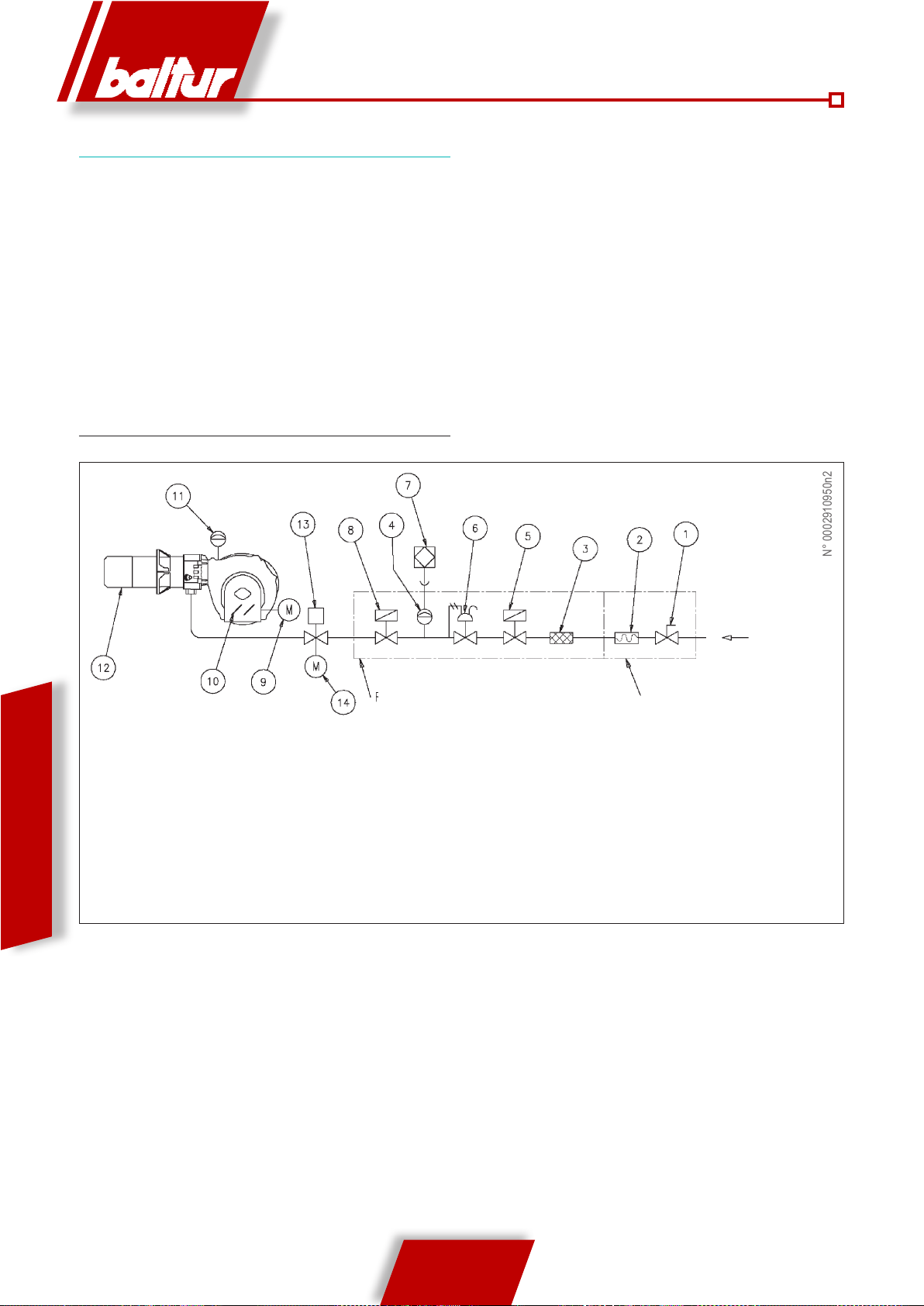
GAS SUPPLY LINE
The gas supply diagram is shown in the figure below.
The gas train is certified in accordance with Standard
EN 676 and is supplied separately from the burner. A
manual shut off valve and an anti-vibration joint must
be installed upstream of the gas valve, as shown in the
diagram.
GENERAL GAS BURNER DIAGRAM
ENGLISH
1) Manual shut off valve
2) Anti-vibration joint
3) Gas filter
4) Minimum gas pressure switch
5) Safety valve
6) Pressure regulator
7) Valve tightness control device
Gas train supplied by the manufacturer
8) Main valve
9) Air adjustment servomotor
10) Air adjustment shutter
11) Air pressure switch
12) Combustion head
13) Gas adjustment butterfly valve
14) Air/gas adjustment servomotor
Responsibility of the installer
8 / 20
0006081531_201203
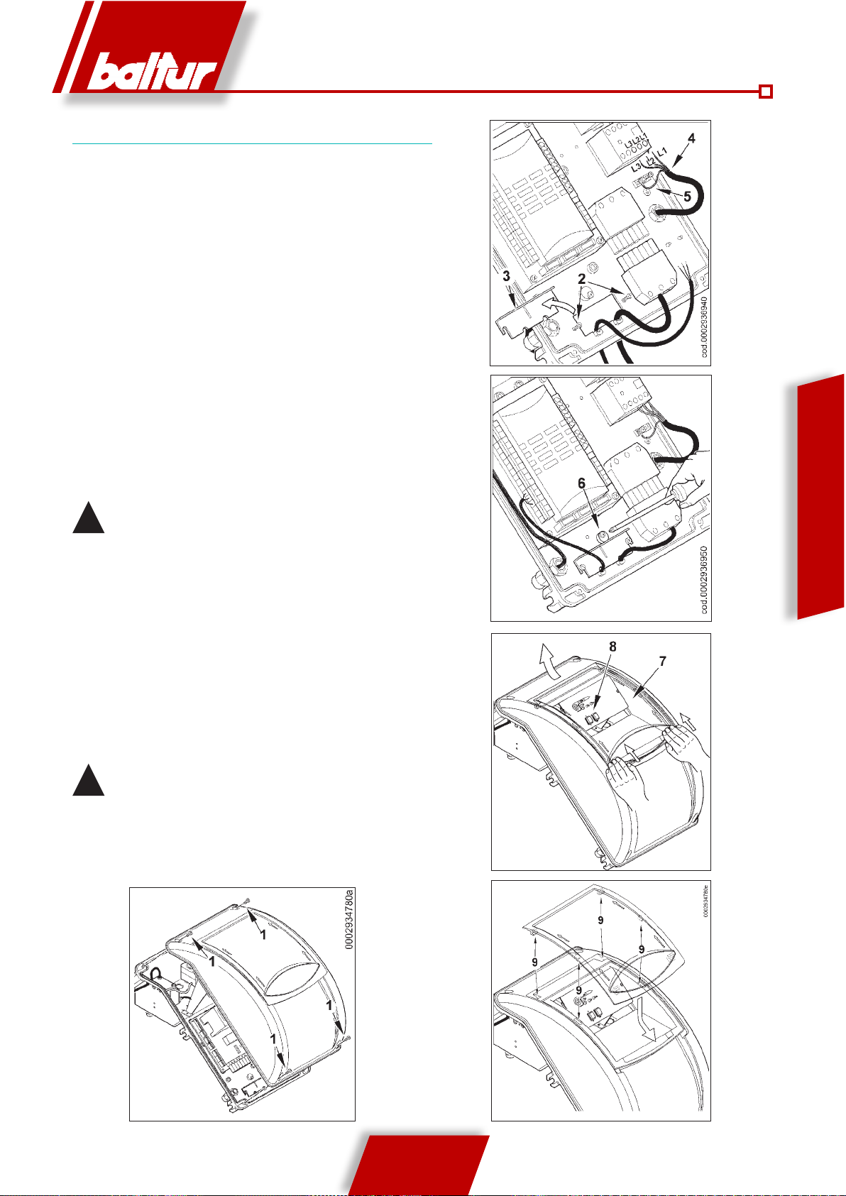
ELECTRICAL CONNECTIONS
The three-phase power supply line must have a switch with fuses.
Moreover, the Standards require a switch on the burner power supply
line, placed outside the boiler room and in an easily accessible position.
For the electrical connections (line and thermostats), follow the attached
wiring diagram. To carry out the connection of the burner to the power
supply line proceed as follows:
1) Remove the lid by unscrewing the 4 screws (1) in figure
1, without removing the transparent door. In this way
the burner’s electrical panel can be accessed.
2) Loosen the screws (2) and after removing the cable
clamp plate (3), make the 7 pole plug and modulation
control cable come through the hole (fig. 2). Connect
the power supply cables (4) to the radio control switch,
fix the earth cable (5) and tighten the cable gland.
3) Reposition the cable clamp plate (fig. 3). Turn the cam
(4) so that the plate exerts sufficient pressure on the
two cables, then tighten the screws that fasten the plate.
Finally connect the 7 pole plug and the modulation
control cables.
The housings for the cables are provided respectively
!
for cable Ø 9.5÷10 mm and Ø 8.5÷9 mm, this ensures the
protection rating is IP 54 (Standard IEC EN60529) for the
electrical panel.
4) To reclose the electrical panel lid, tighten the 4 screws (1) with a
tightening torque of about 5 Nm to ensure correct tightness. At this
point, to access the control panel (8), unhook the transparent door
(7), pressing gently with your hands in the direction of the arrows
shown in figure 4, slide it a short distance to separate it from the
lid.
Fig. 2
ENGLISH
Fig. 3
5) To secure the transparent door on the panel properly, proceed as
indicated in figure 5: position the hooks at their hooking points (9),
slide the door in the direction indicated by the arrow until you hear
a click that ensures its seal.
important: only professionally qualified personnel may open
!
the burner electrical panel.
Fig. 4
9 / 20
0006081531_201203
Fig. 5Fig. 1

DESCRIPTION OF TWO-STAGE
PROGRESSIVE OPERATION
Blown air burners with electronic modulation may be used on
hearths under strong pressure or in a vacuum, according to the
corresponding operating curves. They combine a very stable flame
with total safety and high performance.
The burner is equipped with a LAMTEC electronic cam model “BT
3xx” controlled by a microprocessor with intermittent operation, to
control and monitor blower gas burners with electronic modulation
by means of two regulating motors (air/gas). During operation as
automatic burner, a valve tightness control is also incorporated. To
better understand the operation of the “BT 3xx” electronic cam, read
carefully the instructions in the attached manual.
The term two-stage progressive operation means that transition
from the first to the second stage flame (from minimum to maximum
operation) is progressive in terms of both amount of combustive air
supply and the amount of fuel, offering significant benefits for the
stability of pressure in the gas supply network. Ignition is preceded
by the combustion chamber pre-ventilation (as set forth by the
Standards), with air open and with a duration of approx. 30 seconds.
If the air pressure switch has detected a sufficient pressure, the
ignition transformer activates at the end of the ventilation phase
and after 3 seconds the safety and main valves open in sequence.
ENGLISH
The gas reaches the combustion head, mixes with air supplied by
the fan and ignites. The gas supply is regulated by the butterfly gas
valve. Three seconds after the valves (main and safety) activate,
the ignition transformer switches off. Thus the burner is ignited at
2
the ignition point (
by the control device (ionisation probe immersed in the flame).
The programmer relay moves past the locking position and sends
voltage to the air/gas supply adjustment servomotors, which go
to the minimum point (200). If the second stage boiler thermostat
(or pressure switch) allows it (set to a temperature or pressure
value higher than the existing value in the boiler), the air/gas
supply servomotors will start to turn, gradually increasing gas and
combustion air supplies up to the maximum supply to which the
burner has been set (999).
The “BT 3xx” electronic cam commands the
!
burner, activating the combustive air and gas
servomotor on the basis of a pre-set curve.
The burner remains in the maximum supply position until the
temperature or pressure has reached a sufficient value to cause
the second stage boiler thermostat (or pressure switch) to trip,
which makes the air/gas supply adjustment servomotors turn in the
opposite direction to the previous one, gradually reducing gas and
combustive air supply until the minimum value.
If the limit value (temperature or pressure) at which the stop device
is set (thermostat or pressure switch) is reached even with gas
supply at minimum level, the burner is shut down by the device. As
the temperature or pressure drops below the shut-down device's
set point, the burner will be turned on again as described above.
During normal operation the second stage boiler thermostat (or
pressure switch) applied to the boiler detects variations in demand
and automatically adapts fuel and combustion air supplies, activating
the air/gas supply adjustment servomotors with increasing or
decreasing rotation. This causes the air/gas supply control system
). The presence of the flame is detected
to balance the amount of heat supplied to the boiler with the amount
it gives off during use.
If a flame does not appear within three seconds from the opening
of the gas valves, the control equipment will lockout (shutting down
the boiler completely and showing the corresponding error message
on the display (3)).
To "unlock" the equipment, press the RESET button (4) for about
half a second.
DETAIL OF BUTTERFLY VALVE FOR GAS FLOW
REGULATION BY MEANS OF SERVOMOTOR
farfallaTBG ME
A
B
A Butterfly gas valve position reference index.
B Gas modulation servo motor.
10 / 20
0006081531_201203
NATURAL GAS IGNITION AND ADJUSTMENT
1) The air contained in the piping must be bled out,
with due precautions and with doors and windows
open. Open the fitting on the piping situated near
the burner and then open a little the gas shut-off
valve (or valves). When the characteristic odour of
gas can be smelled, close the shut-off valve. Wait
long enough for the gas in the room to disperse, and
then connect the burner to the gas pipe again and
open the valve again.
2) Check that there is water in the boiler and that the
system gates are open.
3) Make absolutely sure that the products of combustion
can be released freely (boiler shutter valve and flue
open).
4) Make sure that the voltage of the power line to
which the burner is to be connected corresponds
to that required by the burner and that the electrical
connections (motor or main line) are designed for
the voltage rating available. Also check that all the
electrical connections carried out on site are in
accordance with our wiring diagram.
5) Make sure that the combustion head is long enough
to enter the furnace to the extent specified by the
boiler manufacturer. Check that the air adjustment
device on the combustion head is in the correct
position for the fuel supply required (the air passage
between the disk and the head must be reduced
for low supply and relatively wide when supply is
higher). See chapter “Combustion head airflow
adjustment”.
6) Fit a pressure gauge with suitable full scale (where
1
5
1 - Main switch On/Off
2 - Programming keys
3 - Display
4 - Confirm or RESET key
5 - Fuse
3
4
2
the pressure level envisaged allows it, a liquid
column manometer is preferable; do not use pointer
gauges for low pressures) to the pressure outlet port
on the gas pressure switch.
7) With the switch (1) on the mimic panel switched to
“O” and the main switch turned on, manually close
the remote control switch and check that the motor
revolves in the correct direction. If necessary,
exchange the position of the two cables in the line
that feeds the motor in order to reverse the direction
of revolution.
8) Now switch on the main switch. With the control
equipment receivin g elect r i c a l p o w e r, th e
programmer will cause the burner to start up as
described in chapter “Operation description”. For
burner adjustment, refer to the supplied instructions
for the "BT 3xx" electronic cam.
9) After having adjusted the "minimum", (200) bring the
burner towards the maximum, using the controls on
the “BT 3xx” keyboard.
10) We recommend that you check combustion
using the appropriate instrument at all intermediate
points on the modulation route (from 200 to 999),
checking the gas flow rate by reading the meter.
It is essential to check, with a suitable instrument,
that the percentage of carbon monoxide (CO)
present in the fumes does not exceed the limit set
by regulations in force at the time of installation.
11) Now check the proper automatic operation of
modulation. This ensures that the equipment
receives the signal from the electronic modulation
regulator, if the burner is the modulating model,
or from the second stage thermostat or pressure
switch, if it is a two stage progressive burner.
12) The air pressure switch has the purpose of switching the
equipment into the safety (lock-out) status if the air pressure is
not what it should be. The pressure switch must therefore be set
to close the contact (closed during operation) when air pressure
in the burner is sufficient. The pressure switch connection circuit
is self controlling. Therefore, the contact which is meant to be
closed in a non operating status (fan stopped and thus no air
pressure in burner), should in fact be in this status, otherwise
the command/control equipment will not be switched on (burner
remains inoperative). Please note that if the contact meant to
be closed during operation does not close (insufficient air pressure), the equipment carries out its cycle but the ignition transformer is not switched on and the fuel valves do not open. As
a result, the burner stops. To verify that the air pressure switch
is operating correctly, while the burner is ignited at its minimum
setting, increase the adjustment value until the switch triggers
instant “lock” stop of the burner. Release the burner by pushing
the appropriate button and readjust the pressure switch to an
adequate value to detect the existent air pressure during the
pre-ventilation phase.
13) The pressure switches for checking gas pressure (minimum
display lamtec BT3xx
ENGLISH
11 / 20
0006081531_201203
and maximum) prevent the burner from operating when gas pressure
is between the expected values. The specific function of the
pressure switches clearly reveals that the pressure switch for
controlling minimum pressure must use the contact which is
closed when the pressure switch detects a pressure value
above the value it is set to, while the pressure switch for
controlling maximum pressure must use the contact that is
closed when the pressure switch detects a pressure lower
than the value it is set to. Minimum and maximum gas pressure
switches must be set when the burner is tested. Setting depends
on pressure detected from time to time. Tripping of any of the
gas pressure switches (in the sense of opening the circuit) will
therefore prevent the equipment and therefore the burner from
working. When the burner is working (flame on), tripping the
gas pressure switches (opening the circuit) will shut down the
burner immediately. When testing the burner, it is very important
to check that the pressure switches are working properly. By
using the adjustment devices, it can be verified whether the
pressure switch that stops the burner actually operates (i.e.
opens the circuit).
14) Verify the flame detector operation as follows:
- disconnect the wire coming from the ionisation electrode,
- Start up the burner;
ENGLISH
- The equipment will complete the control cycle and after
two seconds will lock the burner due to the lack of ignition
ame;
- switch off the burner;
- Re-connect the wire to the ionisation electrode.
This test should also be conducted with the burner already on;
the equipment should "lock" immediately when the wire from
the ionisation electrode is disconnected.
IONISATION CURRENT MEASUREMENT
The minimum current needed to run the equipment is 1.4 µA. The
burner provides a significantly higher current and therefore does not
normally require any checks at all. Should however, the ionisation
current need to be measured, a microammeter must be connected
in series to the ionisation electrode lead by opening the connector
“C” as illustrated in the figure.
ioniz_BT3xx
15) Check the efficiency of the boiler thermostats or pressure
switches (when tripping they must stop the burner).
Check that ignition occurs normally since if
!
the mixer is not positioned correctly, it may
happen that the speed of the delivery air is so
high that ignition is difficult. If this happens,
the mixer must be shifted back by degrees
until it is in a position in which ignition
occurs normally, and this new position can
be regarded as the final position.
Remember that for the ignition flame, it is better to limit the
amount of air to the amount strictly indispensable to ensure
safe ignition even in the most difficult cases.
12 / 20
0006081531_201203
N°0002934691
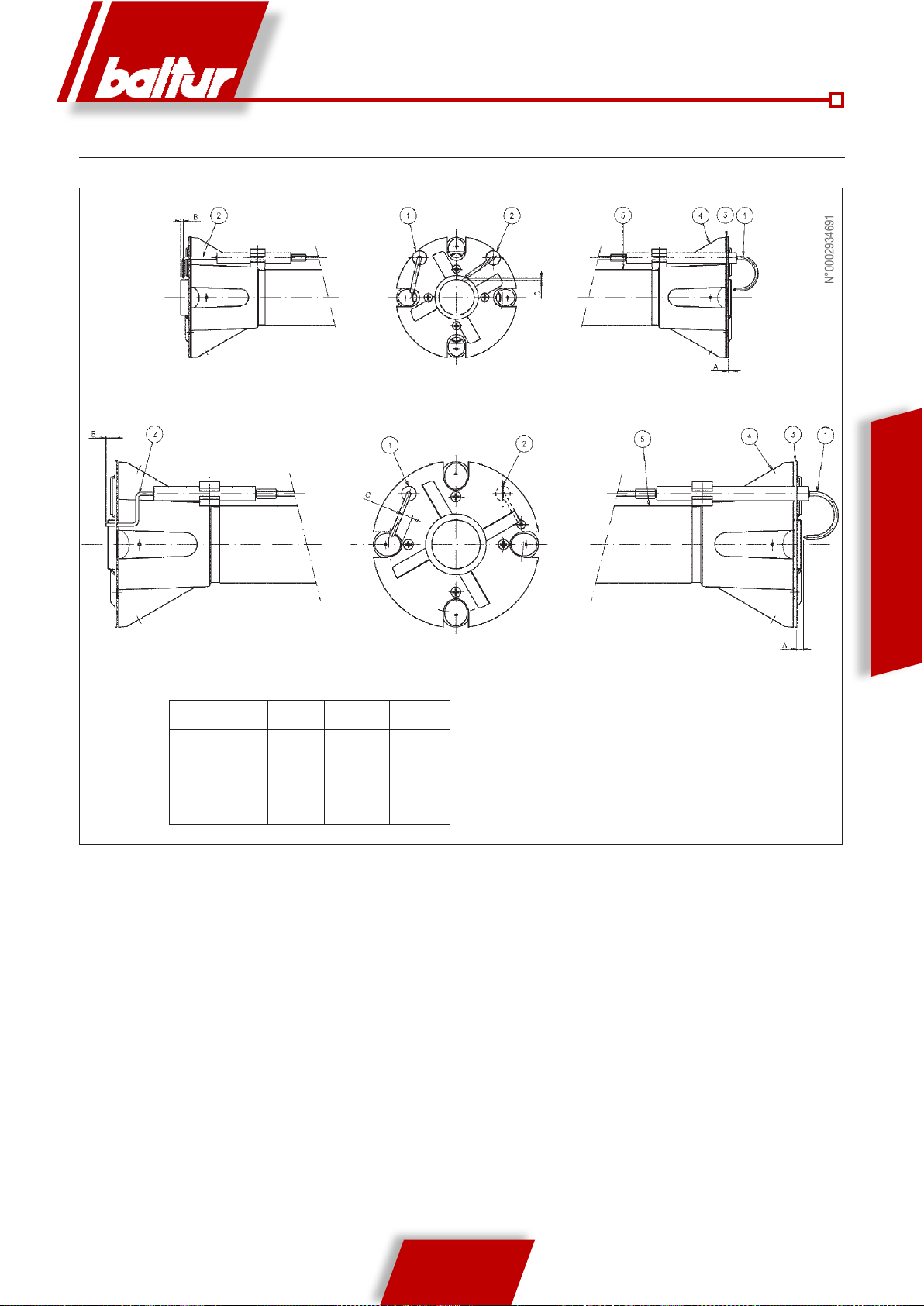
ELECTRODES/IONISATION PROBE ADJUSTMENT DIAGRAM
TBG 85P / 85PN / 85ME,
ENGLISH
TBG 120P / 120PN / 120ME, TBG 150P / 150PN / 150ME,
TBG 210P / 210PN / 210ME
Mod. A B C
TBG 85ME 5 3 3
TBG 120ME 5 5 TBG 150ME 15 5 6
TBG 210ME 5 5 -
1 Ionisation electrode
2 Ignition electrode
3 Flame disk
4 Mixer
5 Gas delivery pipe
13 / 20
0006081531_201203
ADJUSTI NG THE AI R ON THE
COMBUSTION HEAD
The combustion head has an adjustment device so that
the air passage between the disk and the combustion
head can be opened or closed. You are thus able to
obtain, by closing the passage, high pressure upstream
of the disk even at low capacity. The high speed and
turbulence of the air provides for its greater penetration
into the fuel and therefore an excellent mixture and
flame stability. High air pressure upstream of the disk
may be necessary to prevent flame fluctuations, this
is particularly essential when the burner works on the
furnace that is pressurised and/or at a high thermal load.
It is clear from the above that the device that closes the
air to the combustion head must be set at a position
such as to always obtain very high air pressure behind
the disk. It is advisable to adjust it in such a way as to
obtain a closure of the air at the combustion head that
will require a significant opening of the air shutter that
regulates the suction flow from the burner fan. This must
of course be the case when the burner is working at the
required maximum supply.
In practice you have to start the adjustment with the
ENGLISH
device that closes the air at the combustion head in
an intermediate position, switching on the burner for
approximate adjustment as explained previously.
When the required maximum supply has been
reached, the position of the device that closes the
air at the combustion head has to be corrected,
moving it forward and backwards, in order to obtain
an air flow suitable for the supply with the air shutter
considerably open.
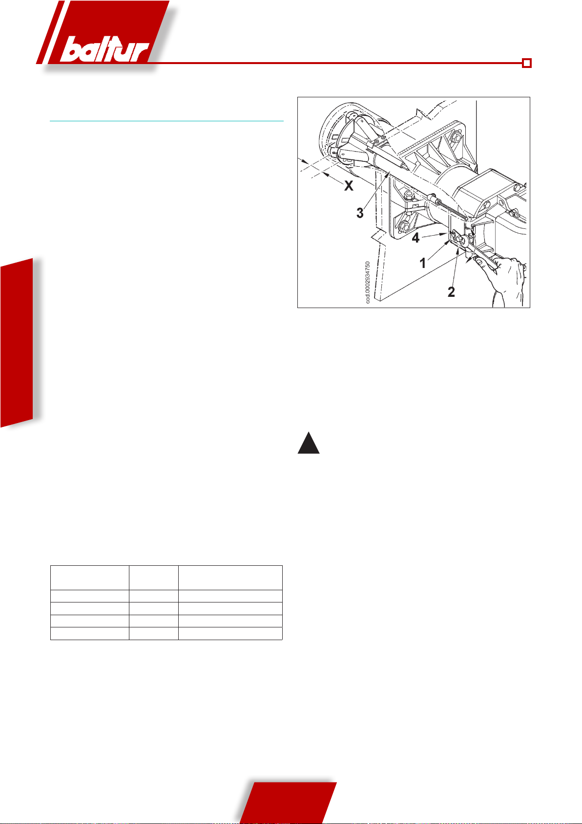
COMBUSTION HEAD ADJUSTMENT DIAGRAM
X= Combustion head-disk distance; adjust the distance X following
the indications below:
a) loosen screw 1
b) turn screw 2 to position the combustion head 3, referring to
index 4.
c) adjust the distance X between minimum and maximum
according the indications in the table.
The above adjustments are indicative only; position the
!
combustion head according to the characteristics of the
combustion chamber
BURNER X Value indicated by index 4
TBG 85ME 5÷ 36 1 ÷ 4.5
TBG 120ME 17÷ 54 1 ÷ 5
TBG 150ME 17÷ 36 1 ÷ 3.2
TBG 210ME 14 ÷ 51 1 ÷ 5
0006081531_201203
14 / 20
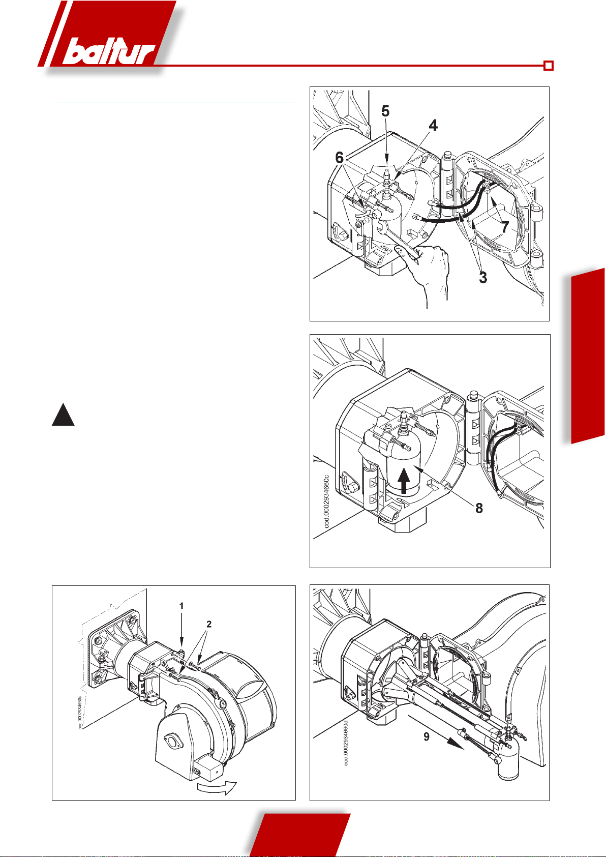
MAINTENANCE
Analyse combustion gases and check that the emission values are
correct at least once a year, in compliance with current law.
Check the fuel filter: if it is dirty, replace it.
Check that all components of the combustion head are in good
condition, have not been deformed by high temperatures and contain
no impurities or deposits from the installation environment or from
poor combustion; check the efficiency of electrodes.
If it is necessary to clean the combustion head, take out its
components according to the procedure described below:
Unscrew the two screws (2) and turn the burner around the pin (1)
in the hinge.
After pulling out the ignition and ionisation cables (3) from the
terminals of the respective electrodes, unscrew completely the
nut (4) and tighten the screw (5), moving it forward inside the gas
delivery fitting (8) far enough to permit subsequent dismantling of
the mixing unit. With the same wrench turn the ball joint (6) in the
direction indicated by the arrow, unhooking the lever that moves the
combustion head forward.
Slightly raise the gas delivery fitting (8) and remove the entire mixing
unit in the direction indicated by the arrow (9). Having completed
the maintenance works, refit the combustion head, following in
reverse order the operations described above, after having checked
the correct position of the ignition and ionisation electrodes (see
0002934691).
When closing the burner, gently pull towards the
!
electrical panel, putting the two ignition and ionisation
cables slightly in tension, then arrange them into their
housings (7) as in figure 2. This will ensure that the two
cables do not get damaged by the fan during burner
operation.
figura-2
ENGLISH
gura 1
15 / 20
0006081531_201203
figura-3
figura-4

HOW TO FIND THE CAUSES OF IMPROPER OPERATION OF TWO-STAGE GAS BURNERS
AND HOW TO RECTIFY THEM
The equipment goes into “lock-out” with
the f lame ( red ligh t on) . Mal functioning is due to the flame
control device.
ENGLISH
The equipment goes into “lock-out”,
gas ows out, but there is no ame
(red light on).
F a u l t i n i g n i t i o n
circuit.
The equipment goes into “lock-out”,
gas ows out, but there is no ame
(red light on)
PROBLEM POSSIBLE CAUSE SOLUTION
1) Disturbance to ionisation current from
ignition transformer.
2) Inefficient flame sensor (ionisation
probe).
3) Flame sensor (ionisation probe) position
incorrect.
4) Ionisation probe or relative earth cable.
5) Flame sensor electrical connection
cut-off.
6) Inefcient draught or fumes passage
blocked.
7) Flame disk or combustion head dirty
or worn.
8) Faulty equipment.
9) No ionisation.
1) Fault in ignition circuit.
2) Ignition transformer cable discharges
to earth.
3) Ignition transformer cable disconnected.
4) Faulty ignition transformer.
5) The distance between electrode and
earth is incorrect.
6) Isolator dirty, therefore the electrode
discharges to earth
1) Air/gas ratio incorrect.
2) Gas piping has not been properly bled
of air (in the case of rst ignition).
3) The gas pressure is insufcient or
excessive.
4) Air passage between disk and head
too narrow.
1) Invert the ignition transformer power
supply (230V side) and check using an
analogue micro-ammeter.
2) Replace the ame sensor
3) Correct the position of the ame sensor,
and then check its efciency by connecting the analogue micro-ammeter.
4) Check visually and using the instrument.
5) Restore the connection.
6) Ensure that the boiler fumes passage
and chimney connection are free.
7) Visually check and replace, if necessary.
8) Replace.
9) If the “earth” of the equipment is not
efcient, the ionisation current cannot
be checked. Check the efciency of the
“earth” at the terminal concerned in the
equipment and at the “earth” connection
of the electric system.
1) Check the ignition transformer power
supply (230V) and high voltage circuit
(electrode to earth or isolator broken
under locking terminal).
2) Replace.
3) Connect.
4) Replace.
5) Position at the correct distance
6) Clean or change the isolator or electrode.
1) Correct the air/gas ratio (there
is probably too much air or very
little gas)
2) Bleed the gas pipe again, taking
great care.
3) Check the gas pressure value at
the time of ignition (use a water
pressure gauge, if possible).
4) Adjust the disk/head opening.
16 / 20
0006081531_201203
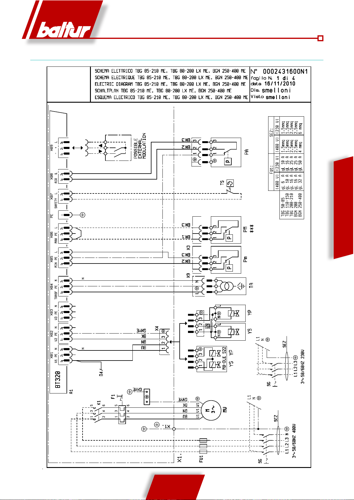
WIRING DIAGRAM
ENGLISH
17 / 20
0006081531_201203
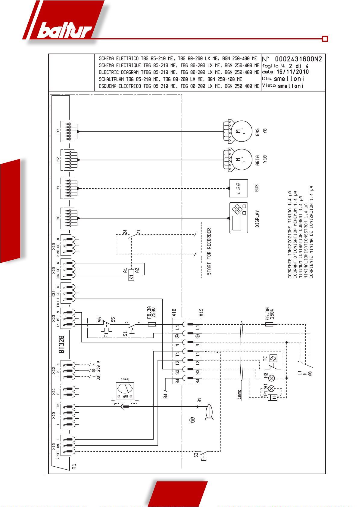
ENGLISH
MINIMUM IONISATION CURRENT 1,5 µA
START FOR RECORDER
18 / 20
0006081531_201203

GAS TEMPERA-
TURE
PROBE
OUTER TEM-
PERATURE
PROBE
WATER TEMPERATURE
PRESSURE PROBE
RELAY COMMAND INPUT
COMMAND INPUT 0/4 - 20 mA
ENGLISH
19 / 20
0006081531_201203
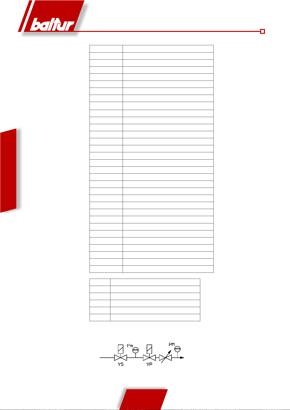
*** POSSIBLE
ENGLISH
ABBREVIATION EN
A1 EQUIPMENT
B1 IONISATION ELECTRODE
BP PRESSURE PROBE
BT 1-3 TEMPERATURE PROBE
DW VALVE TIGHTNESS CONTROL PRESSURE SWITCH
F1 THERMAL RELAY
FU1 FUSES
HO EXTERNAL SHUTDOWN INDICATOR LIGHT
H1 OPERATION LIGHT
K1 MOTOR RELAY
MV MOTOR
N1 ELECTRONIC REGULATOR
P M GAS MAX. PRESSURE SWITCH
P1 HOUR METER
PA AIR PRESSURE SWITCH
Pm GAS MIN. PRESSURE SWITCH
S1 ON-OFF SWITCH
S2 RESET PUSH BUTTON
SG MAIN SWITCH
TA IGNITION TRANSFORMER
TC BOILER THERMOSTAT
TS SAFETY THERMOSTAT
X1 BURNER TERMINAL
X1B/S POWER SUPPLY CONNECTOR
X3 Pm CONNECTOR
X4 YP CONNECTOR
X9 TRANSFORMER CONNECTOR
Y8 GAS SERVOMOTOR
Y10 AIR SERVOMOTOR
YP MAIN ELECTROVALVE
YS SAFETY ELECTROVALVE
DIN / IEC EN
GNYE GREEN / YELLOW
BU BLUE
BN BROWN
BK BLACK
BK* BLACK CONNECTOR WITH OVERPRINT
20 / 20
0006081531_201203

- Antes de empezar a usar el quemador léase atentamente lo expuesto en el folleto “ADVERTENCIAS PARA EL USUARIO, PARA EL
BALTUR S.p.A.
Via Ferrarese 10 - 44042 CENTO (Ferrara) ITALIA
Tel. 051.684.37.11 Fax 051.685.75.27/28
(International Tel. ++39.051.684.37.11 - Fax ++39.051.683.06.86)
http://www.baltur.it - http://www.baltur.com - E-MAIL info@baltur.it
USO CON SEGURIDAD DEL QUEMADOR” presente junto con el manual de instrucciones, que constituye parte integrante y esencial
del producto.
- Leer atentamente las instrucciones antes de poner en funcionamiento los quemadores o efectuar las tareas de mantenimiento.
- Los trabajos que se efectúen al quemador y a la instalación deben ser efectuados solamente por personal cualificado.
- La alimentación eléctrica de la instalación se debe desconectar antes de iniciar los trabajos.
- Si los trabajos ne se llevan a cabo correctamente, se pueden ocasionar accidentes peligrosos.
Declaración de conformidad
Declaramos que nuestros productos
BPM...; BGN…; BT…; BTG…; BTL…; TBML...; Comist…;
GI…; GI…Mist; Minicomist…; PYR…; RiNOx…; Spark...;
Sparkgas...; TBG...;TBL...; TBML ...; TS…; IBR...; IB...
(Variante: … LX, para emisiones reducidas de NOx)
Descripción:
los quemadores por aire a presión de combustibles líquidos, gaseosos y mixtos
para uso residencial e industrial cumplen los requisitos mínimos de las directivas comunitarias:
2009/142/CE ..............................................(D.A.G.)
2004/108/CE ...............................................(C.E.M.)
2006/95/CE .................................................(D.B.T.)
2006/42/CE ................................................(D.M.)
y cumplen las normas europeas:
UNI EN 676:2008 (gas y combinación, lado gas)
UNI EN 267:2002 (diésel y combinación, lado diésel)
Estos productos están marcados con:
0085
Dr. Riccardo Fava
18/11/2010
!
ADVERTENCIAS / NOTAS
CARACTERÍSTICAS TÉCNICAS ..................................................................................................................................................................................... 4
APLICACIÓN DEL QUEMADOR A LA CALDERA
LÍNEA DE ALIMENTACIÓN
CONEXIONES ELÉCTRICAS
DESCRIPCIÓN DEL FUNCIONAMIENTO DE DOS ETAPAS PROGRESIVAS
ENCENDIDO Y REGULACIÓN CON METANO
MEDICIÓN DE LA CORRIENTE DE IONIZACIÓN
REGULACIÓN DEL AIRE EN EL CABEZAL DE COMBUSTIÓN
MANTENIMIENTO
INSTRUCCIONES PARA VERIFICAR LAS CAUSAS DE IRREGULARIDADES EN EL FUNCIONAMIENTO Y SU ELIMINACIÓN
ESQUEMA ELECTRICO
.............................................................................................................................................................................................. 8
.......................................................................................................................................................................................... 9
........................................................................................................................................................................................................... 15
.................................................................................................................................................................................................. 17
i
INFORMACIÓN
............................................................................................................................................................ 7
............................................................................................................................................................... 11
..........................................................................................................................................................12
..................................................................................................................................... 14
Director Gerente/Director General
I
PELIGRO / ATENCIÓN
............................................................................................................... 10
.............................. 16
ESPAÑOL
1 / 20
0006081531_201203

• No hay que obstruir ni reducir las sección de las rejillas de aspiración del
colocado el quemador o una caldera, para evitar que se creen situaciones
de las placa correspondan con los de la red de alimentación (eléctrica,
están cerca de la llama y del eventual sistema de precalentamiento del
combustible y se calientan durante el funcionamiento, permaneciendo ca-
• Cuando se decida no utilizar de nitivamente el quemador, hay que encargar al personal cuali cado profesionalmente que realice las operaciones
a) Desconectar la alimentación eléctrica quitando el cable de alimentación
c) Hacer que sean inocuas las partes que podrían ser potenciales fuentes
• Asegurarse de que quien se ha encargado de la instalación del quemador
lo haya jado rmemente al generador de calor de manera que la llama se
el personal cuali cado profesionalmente tiene que realizar las siguientes
c) Controlar la combustión para evitar que se formen gases no quemados
nocivos o contaminantes, superiores a los límites consentidos por las
e) Comprobar que funcione correctamente el conducto de expulsión de
g) Asegurarse de que en el local donde está la caldera estén las instruc-
rearmándolo manualmente; diríjase al personal cuali cado profesional-
I
ADVERTENCIAS DIRIGIDAS AL USUARIO PARA USAR EL QUEMADOR EN
CONDICIONES DE SEGURIDAD PRELIMINARES
Estas advertencias tienen la nalidad de contribuir a la seguridad cuando
se utilizan las partes que se usan en instalaciones de calefacción de uso
civil y producción de agua caliente para uso sanitario, indicando qué hay
que hacer y las medidas que hay que adoptar para evitar que sus características originarias de seguridad dejen de serlo por una eventual instalación
incorrecta, un uso erróneo, impropio o inadecuado. La difusión de las
advertencias suministradas en esta guía tiene la nalidad de sensibilizar
al público de «consumidores» sobre los problemas de seguridad con un
lenguaje necesariamente técnico pero fácilmente comprensible. Queda
excluida toda responsabilidad contractual y extracontractual del fabricante
por daños causados debidos a errores en la instalación, en el uso y por no
haber respetado las instrucciones dadas por el fabricante en cuestión.
ADVERTENCIAS GENERALES
• El libro de instrucciones constituye una parte integrante y esencial del
producto y tiene que entregarse al usuario. Hay que leer detenidamente
las advertencias contenidas en el libro de instrucciones pues suministran
indicaciones importantes sobre la seguridad de la instalación, el uso y
el mantenimiento. Conserve con cuidado el libro para poder consultarlo
en cualquier momento.
• La instalación del aparato debe realizarse respetando las normas vigentes,
según las instrucciones del fabricante, y tiene que realizarla el personal
cuali cado profesionalmente. Por personal cuali cado profesionalmente
se entiende el que cuenta con una competencia técnica en el sector de la
calefacción de uso civil y producción de agua caliente para uso sanitario
y, en concreto, los centros de asistencia autorizados por el fabricante.
Una instalación errónea pueda causar daños a personas, animales y
cosas, de los que el fabricante no se hace responsable.
• Después de haber quitado todo el embalaje hay que asegurarse de que
el contenido esté íntegro. En caso de dudas no utilice el aparato y diríjase
al proveedor. Las partes del embalaje (jaula de madera, clavos, grapas,
bolsas de plástico, poliestireno expandido, etc.) no tienen que dejarse al
alcance de los niños pues son potenciales fuentes de peligro. Además,
para evitar que contaminen, tienen que recogerse y depositarse en sitios
destinados a dicha nalidad.
• Antes de realizar cualquier operación de limpieza o de mantenimiento hay
que desconectar el aparato de la red de alimentación eléctrica mediante
ESPAÑOL
el interruptor de la instalación con los órganos de corte a tal efecto.
• En caso de avería y/o mal funcionamiento del aparato hay que desactivarlo,
absteniéndose de realizar cualquier intento de reparación o intervención
directa. Diríjase exclusivamente a personal cuali cado profesionalmente.
La eventual reparación de los aparatos tiene que hacerla solamente un
centro de asistencia autorizado por BALTUR utilizando exclusivamente
repuestos originales. Si no se respeta lo anteriormente se puede comprometer la seguridad del aparato. Para garantizar la e cacia del aparato
y para que funcione correctamente es indispensable que el personal
cuali cado profesionalmente realice el mantenimiento periódicamente
ateniéndose a las indicaciones suministradas por el fabricante.
• Si el aparato se vende o pasa a otro propietario, o si usted se muda de
casa y deja el aparato, hay que asegurarse siempre de que el libro de
instrucciones esté siempre con el aparato para que pueda ser consultado
por el nuevo propietario y/o instalador.
• Para todos los aparatos con elementos opcionales o kits ( incluidos los
eléctricos) hay que utilizar solo accesorios originales.
QUEMADORES
• Este aparato está destinado solo al uso para el que ha sido expresamente
previsto: aplicación a calderas, generadores de aire caliente, hornos u
otras cámaras de combustión similares, situados en un lugar resguardado
de agentes atmosféricos. Cualquier otro uso se considera impropio y
por lo tanto peligroso.
• El quemador tiene que instalarse en un local adecuado con aberturas
mínimas de ventilación, según lo que prescriben las normas vigentes,
que sean su cientes para obtener una combustión perfecta.
aire del quemador ni las aberturas de ventilación del local donde está
peligrosas como la formación de mezclas tóxicas y explosivas.
• Antes de conectar el quemador hay que asegurarse de que los datos
gas, gasóleo u otro combustible).
• No hay que tocar las partes calientes del quemador pues normalmente
lientes incluso después de una parada no prolongada del quemador.
siguientes:
del interruptor general.
b) Cerrar la alimentación del combustible por medio de la válvula de
corte y quitar los volantes de mando de su alojamiento.
de peligro.
Advertencias particulares
forme dentro de la cámara de combustión del generador en cuestión.
• Antes de poner en marcha el quemador y por lo menos una vez al año,
operaciones:
a) Regular el caudal del combustible del quemador según la potencia
que requiere el generador de calor.
b) Regular el caudal de aire comburente para obtener un valor de
rendimiento de la combustión que sea por lo menos igual que el
mínimo impuesto por las normas vigentes.
normas vigentes.
d) Comprobar que funcionen bien los dispositivos de regulación y
seguridad.
los productos de la combustión.
f) Al nal de todas las regulaciones controlar que todos los sistemas
de bloqueo mecánico de los dispositivos de regulación estén bien
apretados.
ciones de uso y mantenimiento del quemador.
• Si el quemador se para bloqueándose varias veces no hay que insistir
mente para remediar el problema anómalo.
• El manejo y el mantenimiento tienen que hacerlos solo el personal
cuali cado profesionalmente, respetando las disposiciones vigentes.
2 / 20
0006081531_201203

• En caso de ausencia prolongada del usuario del aparato hay que cerrar
b) abrir inmediatamente puertas y ventanas para crear una corriente de
un aparato de gas para evitar situaciones peligrosas como la formación
descargan en la chimenea los productos de la combustión (humos) a una
mismas hace probablemente que la temperatura disminuya por debajo del
punto de condensación. En una chimenea que trabaja con un régimen de
condensación se forma hollín en la zona de salida a la atmósfera cuando se
quema gasóleo o fuel-oil, o se forma agua de condensación a lo largo de la
chimenea en cuestión, cuando se quema gas (metano, G.L.P., etc.). Según
lo anteriormente mencionado se deduce que las chimeneas conectadas a
I
ADVERTENCIAS DIRIGIDAS AL USUARIO PARA USAR EL QUEMADOR EN
CONDICIONES DE SEGURIDAD PRELIMINARES
ALIMENTACIÓN ELÉCTRICA
• La seguridad eléctrica del aparato se consigue solo cuando el mismo
está conectado correctamente a una buena instalación de puesta a
tierra, realizado tal y como establecen las normas de seguridad vigentes. Es necesario comprobar este requisito de seguridad fundamental.
En caso de dudas, pida al personal cuali cado profesionalmente que
haga un control detenido de la instalación eléctrica pues el fabricante
no se hace responsable de los posibles daños causados por la falta
de puesta a tierra de la instalación.
• Haga que el personal cuali cado profesionalmente controle que la
instalación eléctrica sea adecuada a la potencia máxima absorbida
por el aparato, indicada en la placa, comprobando concretamente que
la sección de los cables de la instalación sea idónea a la potencia
absorbida por el aparato.
• Para la alimentación general del aparato de la red eléctrica no está
permitido el uso de adaptadores, enchufes múltiples y/o alargaderas.
• Para la conexión a la red hay que poner un interruptor omnipolar
como prevé la normativa de seguridad vigente.
• La alimentación eléctrica del quemador tiene que tener el neutro a
tierra. En caso de supervisión de la corriente de ionización con el
neutro no conectado a tierra es indispensable conectar entre el borne
2 (neutro) y la tierra el circuito RC.
• El uso de cualquier componente que utilice energía eléctrica comporta
el respeto de algunas reglas fundamentales como:
- no tocar el aparato con partes del cuerpo mojadas o húmedas y/o
con los pies descalzos.
- no tirar de los cables eléctricos
- no dejar el aparato expuesto a agentes atmosféricos (lluvia, sol, etc.)
de no ser que no esté expresamente previsto.
- no permitir que el aparato lo usen niños o personas inexpertas.
• El cable de alimentación del aparato no tiene que cambiarlo el
usuario. En caso de que el cable esté roto, apague el aparato y para
cambiarlo, diríjase exclusivamente a personal profesionalmente
cuali cado.
• Si decide no utilizar el aparato durante un cierto periodo es oportuno
apagar el interruptor eléctrico de alimentación de todos los componentes de la instalación que utilizan energía eléctrica (bombas, quemador,
etc.).
ALIMENTACIÓN CON GAS, GASÓLEO U OTROS COMBUSTIBLES
Advertencias generales
• La instalación del quemador tiene que realizarla el personal profesionalmente cuali cado y debe ajustarse a las normas y disposiciones
vigentes, ya que una instalación errónea puede causar daños a
personas, animales o cosas, de los que el fabricante no puede ser
considerado responsable.
• Antes de la instalación se aconseja hacer una buena limpieza de todos los tubos de la instalación de abastecimiento del combustible para
evitar posibles residuos que podrían comprometer el buen funcionamiento del quemador.
• La primera vez que se pone en funcionamiento el aparato, el personal
cuali cado profesionalmente tiene que controlar:
a) la estanqueidad en el tramo interior y exterior de los tubos de
abastecimiento del combustible;
b) la regulación del caudal del combustible según la potencia
requerida por el quemador;
c) que el quemador esté alimentado por el tipo de combustible para
el que ha sido diseñado;
d) que la presión de alimentación del combustible esté comprendida dentro de los valores indicados en la placa del quemador;
e) que la instalación de alimentación del combustible esté dimensionada para el caudal necesario del quemador y que tenga todos los
dispositivos de seguridad y control prescritos por las normas
vigentes.
• Si se decide no utilizar el quemador durante un cierto periodo hay que
cerrar la llave o llaves de alimentación del combustible.
Advertencias particulares para el uso del gas
• El personal cuali cado profesionalmente tiene que controlar:
a) que la línea de abastecimiento de combustible y la rampa se
ajusten a las normativas vigentes.
b) que todas las conexiones del gas sean estancas.
• No utilizar los tubos del gas como puesta a tierra de aparatos eléctricos.
• No dejar el aparato inútilmente conectado cuando no se utilice y cerrar
siempre la llave del gas.
la llave principal que abastece gas al quemador.
• Si se advierte olor de gas:
a) no accionar los interruptores eléctricos, el teléfono ni cualquier otro
objeto que pueda provocar chispas;
aire que puri que el local;
c) cerrar las llaves del gas;
d) pedir que intervenga el personal cuali cado profesionalmente.
• No obstruir las aberturas de ventilación del local donde está instalado
de mezclas tóxicas y explosivas.
CHIMENEAS PARA CALDERAS DE ALTO RENDIMIENTO Y SIMILARES
Es oportuno precisar que las calderas de alto rendimiento y similares
temperatura relativamente baja. En el caso arriba mencionado las chimeneas tradicionales, dimensionadas comúnmente (sección y aislamiento
térmico) pueden no ser adecuadas para funcionar correctamente pues
el enfriamiento que los productos de la combustión sufren al recorrer las
calderas de alto rendimiento y similares tienen que estar dimensionadas
(sección y aislamiento térmico) para su uso especí co para evitar el inconveniente arriba descrito.
ESPAÑOL
3 / 20
0006081531_201203
CARACTERÍSTICAS TÉCNICAS
TBG 85ME TBG 120ME TBG 150ME TBG 210ME
POTENCIA TÉRMICA
FUNCIONAMIENTO Biestadio progresivo / modulante
EMISIONES NOx mg/kWh < 120 (Clase II según EN 676)
MOTOR
POTENCIA ELÉCTRICA ABSORBIDA* kW 1,20 1,60 2,40 3,2
FUSIBLE DE LÍNEA A 400 V 6 10 10 16
TRANSFORMADOR DE ENCENDIDO 26 kV - 40 mA – 230 V / 50 Hz
TENSIÓN 3N ~ 400 V ±10%- 50 Hz
GRADO DE PROTECCIÓN IP 40
DETECCIÓN DE LLAMA SONDA DE IONIZACIÓN
RUIDO dBA 73 75,5 79 85
PESO kg 78 87 91 94
GAS NATURAL (G 20)
CAUDAL
PRESIÓN MÁX. mbar 500
*) Absorción total, en fase de departida, con transformador de encendido activado.
**) Presión sonora medida en el taller del fabricante, con quemador activo en la caldera de prueba, con caudal térmico nominal máximo
MÁX kW 850 1200 1500 2100
MÍN kW 170 240 300 400
kW 1,1 1,5 2,2 3
r.p.m. 2800 2800 2800 2800
MÁX. m³n/h 85,5 120,7 150,9 211,2
MÍN m³n/h 17 24,1 30,2 40,3
MATERIAL PROPORCIONADO TBG 85ME TBG 120ME TBG 150ME TBG 210ME
BRIDA DE CONEXIÓN DEL QUEMADOR 2 2 2 2
JUNTA AISLANTE 1 1 1 1
PRISIONEROS N° 4 M 12 N° 4 M 12 N° 4 M 12 N° 4 M 12
ESPAÑOL
TUERCAS / EXAGONAL NUTS N° 4 M 12 N°4 M 12 N° 4 M 12 N° 4 M 12
ARANDELAS PLANAS N° 4 Ø 12 N° 4 Ø 12 N° 4 Ø 12 N° 4 Ø 12
CARACTERÍSTICAS TÉCNICO FUNCIONALES
• Funcionamiento en dos etapas progresivas / modulantes de
potencia.
• Regulación del gas mediante válvula de mariposa, accionada
por un servomotor paso a paso, controlado electrónicamente.
• Cabezal de combustión de recirculación parcial de los gases
quemados de emisiones reducidas de NOx (clase II).
• Elevado rendimiento de ventilación, bajas absorciones
eléctricas, bajo ruido.
• Bisagra con apertura en los dos sentidos para acceder cómodamente
a la cabeza de combustión con el quemador montado.
• Regulación del caudal del aire con válvula de apertura
lineal movida por un servomotor paso a paso, accionado
electrónicamente.
• Cierre de la válvula de aire en pausa.
• Cuadro eléctrico predispuesto con conexión mediante clavijas/
tomas (suministradas) de 4 y 7 polos.
• Cuadro eléctrico con grado de protección IP55.
• Brida de conexión al generador deslizante para adaptar el
saliente del cabezal a los distintos tipos de generadores de
calor.
• Elevada relación de modulación1:5.
• Posibilidad de salida de la rampa del gas desde arriba o desde
abajo.
4 / 20
0006081531_201203
2
4
6
8
0
10
12
14
mbar
15015200 300 400 500 600 700 800 900 1000 1100
20 30 40 50 60 70 80 90
100 110
6 8 10 12 14 16 18 20 22 24 26 28 30 32 34 36 38 40 42 44
m
n³/h(Metano)
m
n³/h(G.P.L.)
kW
1200 1300
120 130
46 48 50
1400 1500 1600
16
140 150 160
52 54 56 58 60 62
1700 1800 1900
2000
170 180 190
200
64 66 68 70 72 74 76 78
2100
210
80 82
TBG 85ME
TBG 120ME TBG 150ME
TBG 210ME
CARACTERÍSTICAS CONSTRUCTIVAS
El quemador está compuesto por:
• Entrada del aire comburente dotado de inserto de material
fonoabsorbente, y diseñado para obtener una óptima linealidad
de la apertura de la válvula del aire.
• Panel de mandos con sinóptico de funcionamiento con testigos
luminosos.
• Equipo electrónico de mando y control según la norma EN298,
con microprocesador, con control de estanqueidad de las
válvulas integrado, con capacidad de conexión eBus.
• Pantalla de visualización de la secuencia de funcionamiento y
del código de las anomalías.
• Detección de la llama mediante electrodo ionizador.
• Rampa de gas con válvula de seguridad y de funcionamiento
por accionamiento electromagnético, presóstato de mínima,
regulador de presión y filtro del gas.
• Conectores inteligentes quemador/rampa (a prueba de error).
CAMPO DE TRABAJO
Los campos de trabajo se obtienen en calderas de prueba conformes
a la norma EN676 y son indicativos para los acoplamientos del
quemador-caldera. Para el funcionamiento correcto del quemador
las dimensiones de la cámara de combustión deben conformarse
con la normativa vigente; de lo contrario, hay que consultarse con
los fabricantes.
0006081531_201203
5 / 20
0002922800
ESPAÑOL
N° 0002471120
DIMENSIONES TOTALES
TBG 85ME 610 240 370 520 380 200 1265 175 400 180 178 280 250 325 M12 190
TBG 120ME 610 240 370 540 380 200 1265 200 450 224 219 320 280 370 M12 235
TBG 150ME 610 240 370 540 380 200 1265 200 450 240 219 320 280 370 M12 250
TBG 210ME 610 240 370 540 380 200 1315 200 450 250 219 320 280 370 M12 255
COMPONENTES EL CUADRO ELÉCTRICO
ESPAÑOL
1) Cabezal de combustión
2) Junta
3) Brida de unión al quemador
4) Dispositivo de regulación del cabezal
5) Bisagra
MOD. A A1 A2 B B1 B6 C
10) Equipo
11) Presóstato del aire
12) Transformador de encendido
13) Contactor motor
6) Brida de conexión a la rampa del gas
7) Cuadro eléctrico
8) Motor
9) Servomotor de regulación del aire
9a) Servomotor de regulación del gas
D
MÍN.DMÁX.
E F I
L
MÍN.LMÁX.
M N
14) Relé térmico
15) Clavija 7 polos
16) Panel sinóptico
6 / 20
0006081531_201203
APLICACIÓN DEL QUEMADOR A LA
CALDERA
MONTAJE DEL GRUPO CABEZAL
A) Adecuar la posición de la brida de conexión 5
aflojando los tornillos 6 de modo que el cabezal de
combustión penetre en la cámara de combustión
en la cantidad aconsejada por el fabricante del
generador.
B) Colocar en el tubo la junta aislante 3 interponiendo
la cuerda 2 entre la brida y la junta.
C) Fijar los Grupos Cabezal 4 a la caldera 1 mediante
lo s prisioneros, las arandel as y las tue rcas
correspondientes que se suministran 7.
Sellar completamente con material adecuado el espacio
!
situado entre el tubo del quemador y el orificio en el
refractario dentro de la tapa de la caldera.
MONTAJE DE LA RAMPA DE GAS
Son posibles diversas soluciones de montaje 8, 8a, 9 de
la rampa de las válvulas como se muestra en el dibujo
de al lado. Seleccionar la posición más lógica en base
a la conformación del local de la caldera y a la posición
de llegada de las tuberías del gas.
Con válvulas de dimensiones notables, por ej. DN65 o
!
DN80 prever un soporte adecuado para evitar esfuerzos
excesivos en el empalme de conexión de la rampa del
gas.
MONTAJE DEL CUERPO VENTILANTE
A) Colocar las semibisagras presentes en el caracol
del quemador en correspondencia con las presentes
en el grupo del cabezal.
B) Introducir el perno de la bisagra 10 en la posición
que se considere más idónea.
C) Conectar los cables (encendido e ionización) a
los electrodos correspondientes, cerrar la bisagra
fijando el quemador mediante los tornillos 11.
0006081531_201203
ESPAÑOL
7 / 20
N° 0002910950n2
LÍNEA DE ALIMENTACIÓN
La pantalla del principio de la línea de alimentación
del gas se muestra en la figura de debajo. La rampa
del gas está homologada según la normativa EN 676
y se proporciona de forma separada del quemador. Es
preciso instalar, antes de la válvula del gas, una válvula
de detección manual y una junta antivibrante, colocados
según lo que se indica en el esquema.
ESQUEMA DE PRINCIPIO DEL QUEMADOR DEL
GAS
ESPAÑOL
Rampa de gas suministrada por el fabricante
1) Válvula de detección manual
2) Junta antivibrante
3) Filtro del gas
4) Presóstato de presión mínima del gas
5) Válvula de seguridad
6) Regulador de presión
7) Dispositivo de control de la estanqueidad de las válvulas
A cargo del instalador
8) Válvula de trabajo
9) Servomotor de regulación del aire
10) Clapeta de regulación del aire
11) Presóstato del aire
12) Cabezal de combustión
13) Válvula de mariposa de regulación del gas
14 Servomotor de regulación del gas
8 / 20
0006081531_201203
 Loading...