

baltur TBG 1100 MC Manual User Instructions

UK
SP
TR
РУС
Manual user instructions.
Manual de instrucciones
de uso.
Kullanım talimatları
kılavuzu.
Инструкция по
эксплуатации
中文
使用说明
TBG 1100 MC
- TWO-STAGE MODULATING/PRORESSIVE OUTPUT GAS BURNER
- QUEMADORES DE GAS EL PROGRESO DE LAS FASES / MODULAR
- GAZ BRÜLÖRÜ PROGRESİF /MODÜLER FAZLARI
- ГАЗОВЫЕ ДВУХСТУПЕНЧАТЫЕ ПРОГРЕССИВНЫЕ/
МОДУЛЯЦИОННЫЕ ГОРЕЛКИ
两段火渐进式/比例调节式燃气燃烧器
-
ORIGINAL INSTRUCTIONS (IT)
I
STRUCTIONS ORIGINALES (IT)
ORİJİNAL KULLANIM KILAVUZU (IT)
ОРИГИНАЛЬНЫЕ ИНСТРУКЦИИ
(
ПЕРЕВОД С ИТАЛЬЯНСКОГО ЯЗЫКА
正版说明书。(IT)
0006160025_201305
)


• Before starting to use the burner, read the chapter “WARNING NOTES FOR THE USER: HOW TO USE THE BURNER SAFELY” in
this instruction manual carefully, which is an integral and essential part of the product.
• Carefully read the instructions before starting or maintaining the burner.
• The works on the burner and on the system have to be carried out only by qualified personnel.
• The system electric feeding must be disconnected before starting working on it. If the works are not carried out correctly it is possible
to cause dangerous accidents.
ENGLISH
DANGER
WARNINGS ATTENTION
INFORMATION
1 / 28
0006160025_201305

Declaration of Conformity
We declare that our products
BPM...; BGN…; BT…; BTG…; BTL…; TBML...; Comist…;
GI…; GI…Mist; Minicomist…; PYR…; RiNOx…; Spark...;
Sparkgas...; TBG...;TBL...; TBML ...; TS…; IBR...; IB...
(Variant: … LX, for low NOx emissions)
ENGLISH
Description:
forced air burners of liquid, gaseous and mixed fuels for residential and
industrial use meet the minimum requirements of the European Directives:
2009/142/CE ..............................................(D.A.G.)
2004/108/CE ...............................................(C.E.M.)
2006/95/CE .................................................(D.B.T.)
2006/42/CE ................................................(D.M.)
and conform to European Standards:
UNI EN 676:2008 (gas and combination, gas side)
UNI EN 267:2002 (diesel and combination, diesel side)
These products are therefore marked:
0085
18/11/2010
Dr. Riccardo Fava
Managing Director / CEO
TECHNICAL DATA ........................................................................................................................................................................................................5
BURNER CONNECTION TO THE BOILER .............................................................................................................................................................7
ELECTRICAL CONNECTIONS ..................................................................................................................................................................................9
ASSEMBLING THE GAS TRAIN ................................................................................................................................................................................10
COMMAND AND CONTROL EQUIPMENT FOR GAS BURNERS LFL 1...... ..................................................................................................12
DETAILS OF THE MODULATION CONTROL MOTOR SQM 10 AND SQM 20 FOR REGULATION OF CAMS ........................................16
IGNITION AND ADJUSTMENT ...................................................................................................................................................................................17
HOW TO FIND THE CAUSES OF IMPROPER OPERATION OF TWO-STAGE GAS BURNERS AND HOW TO RECTIFY THEM .......23
WIRING DIAGRAM ...................................................................................................................................................................................
..........................................................................................................................................................................................................................................24
2 / 28
0006160025_201305

WARNING NOTES FOR THE USER HOW TO USE THE BURNER SAFELY
FOREWORD
These warning notes are aimed at ensuring the safe use of the components of heating systems for civil use and the production of hot water.
They indicate how to act to avoid the essential safety of the components
being compromised by incorrect or erroneous installation and by improper
or unreasonable use. The warning notes provided in this guide also seek
to make the consumer more aware of safety problems in general, using
necessarily technical but easily understood language. The manufacturer
is not liable contractually or extra contractually for any damage caused
by errors in installation and in use, or where there has been any failure to
follow the manufacturer’s instructions.
GENERAL WARNING NOTES
• The instruction booklet is an integral and essential part of the product
and must be given to the user. Carefully read the warnings in the booklet as they contain important information regarding safe installation,
use and maintenance. Keep the booklet to hand for consultation when
needed.
• Equipment must be installed in accordance with current regulations,
with the manufacturer’s instructions and by qualifi ed technicians. By
the term ‘qualifi ed technicians’ is meant persons that are competent in
the fi eld of heating components for civil use and for the production of
hot water and, in particular, assistance centres authorised by the manufacturer. Incorrect installation may cause damage or injury to persons,
animals or things. The manufacturer will not in such cases be liable.
• After removing all the packaging make sure the contents are complete
and intact. If in doubt do not use the equipment and return it to the
supplier. The packaging materials (wooden crates, nails, staples, plastic
bags, expanded polystyrene, etc.) must not be left within reach of children as they may be dangerous to them. They should also be collected
and disposed on in suitably prepared places so that they do no pollute
the environment.
• Before carrying out any cleaning or maintenance, switch off the equip-
ment at the mains supply, using the system’s switch or shut-of f systems.
• If there is any fault or if the equipment is not working properly, de-ac-
tivate the equipment and do not attempt to repair it or tamper with it
directly. In such case get in touch with only qualifi ed technicians. Any
product repairs must only be carried out by BALTUR authorised assistance centres using only original spare parts. Failure to act as above
may jeopardise the safety of the equipment. To ensure the effi ciency
and correct working of the equipment, it is essential to have periodic
maintenance carried out by qualifi ed technicians following the manufac-
turer’s instructions.
• If the equipment is sold or transferred to another owner or if the owner
moves and leaves the equipment, make sure that the booklet always
goes with the equipment so it can be consulted by the new owner and/
or installer.
• For all equipment with optionals or kits (including electrical), only origi-
nal accessories must be used.
BURNERS
• This equipment must be used only for its expressly stated use: applied
to boilers, hot air boilers, ovens or other similar equipment and not
exposed to atmospheric agents. Any other use must be regarded as
improper use and hence dangerous.
• The burner must be installed in a suitable room that has ventilation in
accordance with current regulations and in any case suffi cient to ensure
correct combustion
• Do not obstruct or reduce the size of the burner’ air intake grills or the
ventilation openings for the room where a burner or a boiler is installed
or dangerous mixtures of toxic and explosive gases may form.
• Before connecting the burner check that the details on the plate correspond to those of the utility supplies (electricity, gas, light oil or other
fuel).
• Do not touch hot parts of the burner. These, normally in the areas near
to the fl ame and any fuel pre-heating system, become hot when the
equipment is working and stay hot for some time after the burner has
stopped.
• If it is decided not to use the burner any more, the following actions must
be performed by qualifi ed technicians:
a) Switch off the electrical supply by disconnecting the power cable from
the master switch.
b) Cut off the fuel supply using the shut-off valve and remove the control
wheels from their position.
c) Render harmless any potentially dangerous parts.
Special warning notes
• Check that the person who carried out the installation of the burner fi xed
it securely to the heat generator so that the fl ame is generated inside
the combustion chamber of the generator itself.
• Before starting up the burner, and at least once a year, have qualifi ed
technicians perform the following operations:
a) Set the burner fuel capacity to the power required by the heat ge-
nerator.
b) Adjust the combustion air fl ow to obtain combustion yield of at least
the minimum set by current regulations.
c) Carry out a check on combustion to ensure the production of no-
xious or polluting unburnt gases does not exceed limits permitted
by current regulations.
d) Check the adjustment and safety devices are working properly.
e) Check the effi ciency of the combustion products exhaust duct.
f) Check at the end of the adjustments that all the adjustment devices
mechanical securing systems are properly tightened.
g) Make sure that the use and maintenance manual for the burner is
in the boiler room.
• If the burner repeatedly stops in lock-out, do not keep trying to manually
reset but call a qualifi ed technicians to sort out the problem.
• The running and maintenance of the equipment must only be carried
out by qualifi ed technicians, in compliance with current regulations.
ENGLISH
3 / 28
0006160025_201305

WARNING NOTES FOR THE USER HOW TO USE THE BURNER SAFELY
ELECTRICAL SUPPLY
• The equipment is electrically safe only when it is correctly connected to an
effi cient ground connection carried out in accordance with current safety
regulations. It is necessary to check this essential safety requirement.
If in doubt, call for a careful electrical check by a qualifi ed technicians,
ENGLISH
since the manufacturer will not be liable for any damage caused by a
poor ground connection.
• Have qualifi ed technicians check that the wiring is suitable for the
maximum power absorption of the equipment, as indicated in the technical
plate, making sure in particular that the diameter of cables is suffi cient
for the equipment’s power absorption.
• Adapters, multiple plugs and extension cables may not be used for the
equipment’s power supply.
• According to current safety regulations, an omnipolar switch with a contact
opening gap of at least 3 mm is required for the mains supply connection.
• Extract the power cable external insulation as strictly necessary for the
connection, in order to avoid that the cable comes into contact with metal
parts.
• An ominpolar switch in accordance with current safety regulations is
required for the mains supply connection.
• The electrical supply to the burner must have neutral to ground
connection. If the ionisation current has control with neutral not to ground
it is essential to make a connection between terminal 2 (neutral) and the
ground for the RC circuit.
• The use of any components that use electricity means that certain
fundamental rules have to followed, including the following:
- do not touch the equipment with parts of the body that are wet or damp
or with damp feet
- do not pull on electrical cables
- do not leave the equipment exposed to atmospheric agents (such as
rain or sun etc.) unless there is express provision for this.
- do not allow the equipment to be used by children or inexpert persons.
• The power supply cable for the equipment not must be replaced by the
user. If the cable gets damaged, switch off the equipment, and call only
on qualifi ed technicians for its replacement.
• If you decide not to use the equipment for a while it is advisable to switch
off the electrical power supply to all components in the system that use
electricity (pumps, burner, etc.).
a) that the feed line and the train comply with current law and regulations.
b) that all the gas connections are properly sealed.
• Do not use the gas pipes to ground electrical equipment.
• Do not leave the equipment on when it is not in use and always close
the gas tap.
• If the user of is away for some time, close the main gas feed tap to the
burner.
• If you smell gas:
a) do not use any electrical switches, the telephone or any other object
that could produce a spark;
b) immediately open doors and windows to create a current of air that
will purify the room;
c) close the gas taps;
d) ask for the help of qualifi ed technicians.
• Do not block ventilation openings in the room where there is gas
equipment or dangerous situations may arise with the build up of toxic
and explosive mixtures.
FLUES FOR HIGH EFFICIENCY BOILERS AND SIMILAR
It should be pointed out that high effi ciency boilers and similar discharge
combustion products (fumes) at relatively low temperatures into the fl ue.
In the above situation, traditional fl ues (in terms of their diameter and heat
insulation) may be suitable because the signifi cant cooling of the combustion
products in these permits temperatures to fall even below the condensation
point. In a fl ue that works with condensation there is soot at the point the
exhaust reaches the atmosphere when burning light oil or heavy oil or the
presence of condensate water along the fl ue itself when gas is being burnt
(methane, LPG, etc.). Flues connected to high effi ciency boilers and similar
must therefore be of a size (section and heat insulation) for the specifi c use
to avoid such problems as those described above.
GAS, LIGHT OIL, OR OTHER FUEL SUPPLIES
General warning notes
• Installation of the burner must be carried out by qualifi ed technicians
and in compliance with current law and regulations, since incorrect
installation may cause damage to person, animals or things, for which
damage the manufacturer shall not can be held responsible.
• Before installation it is advisable to carry out careful internal cleaning
of all tubing for the fuel feed system to remove any residues that could
jeopardise the proper working of the burner.
• For fi rst start up of the equipment have qualifi ed technicians carry out
the following checks:
• If you decide not to use the burner for a while, close the tap or taps that
supply the fuel.
Special warning notes when using gas
• Have qualifi ed technicians check the following:
0006160025_201305
4 / 28
TECHNICAL DATA
THERMAL CAPACITY
FAN MOTOR
ABSORBED ELECTRICAL POWER
IGNITION TRANSFORMER
MAX kW
MIN kW
kW
TBG 1100 MC
11000
1000
22 kW - 50 Hz
.
2940 rev./min
23
ENGLISH
8 kV - 30 mA
POWER SUPPLY VOLTAGE
FLAME DETECTOR IONISATION ELECTRODE
SUPPLIED MATERIAL
INSULATING SEAL
STUD BOLTS
HEXAGON NUTS
FLAT WASHERS
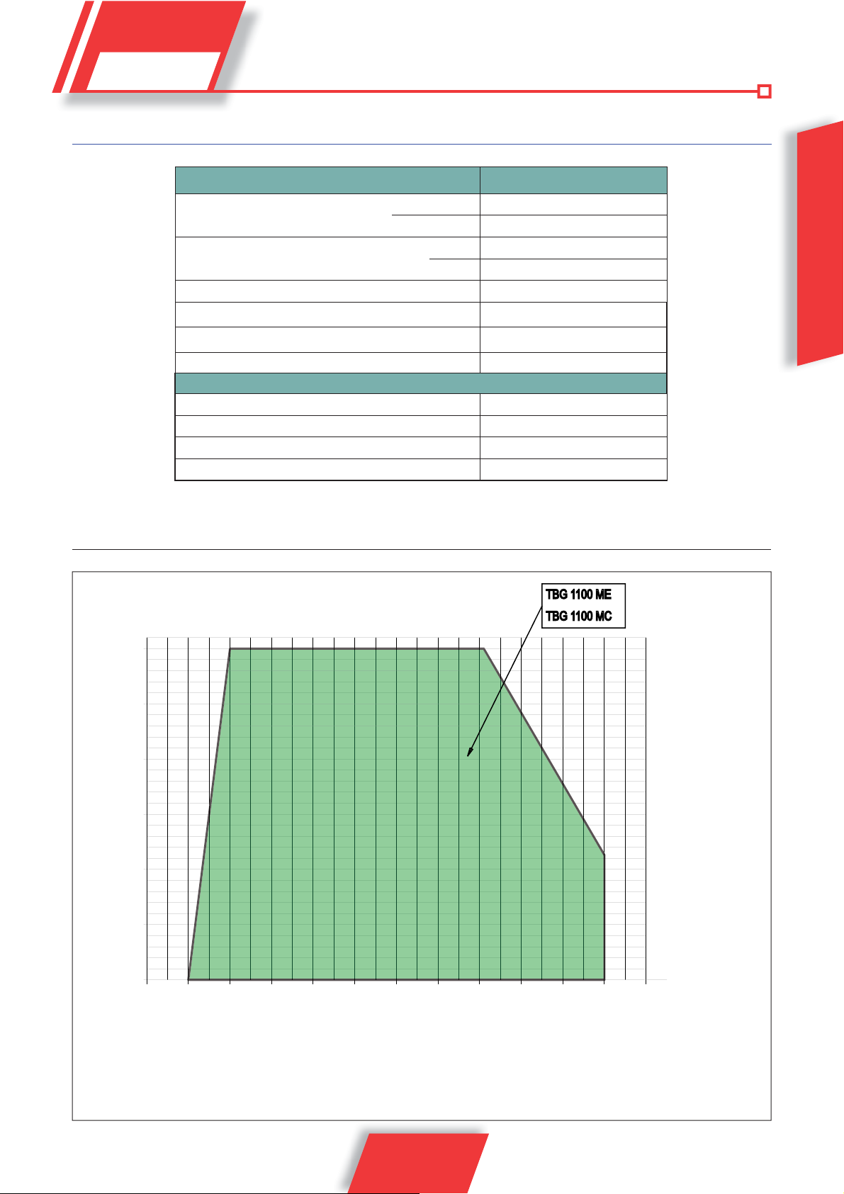
OPERATING RANGE
mbar
26
25
3N ~ 400 V - 50 Hz
2
No. 4 M 20
No. 4 M 20
No. 4 Ø 20
0002922900
20
15
10
5
0
234567
1 8910 11 12
The operating ranges are obtained from test boilers corresponding to Standard EN676 and are
indicative of the burner-boiler combination. For correct working of the burner the size of the combustion
chamber must correspond to current regulations; if not the manufacturers must be consulted.
The operating ranges have been obtained at a room temperature of 20°C and at a barometric pressure of 1013
mbar (around 0 metres above sea level).
5 / 28
0006160025_201305
kWx1000

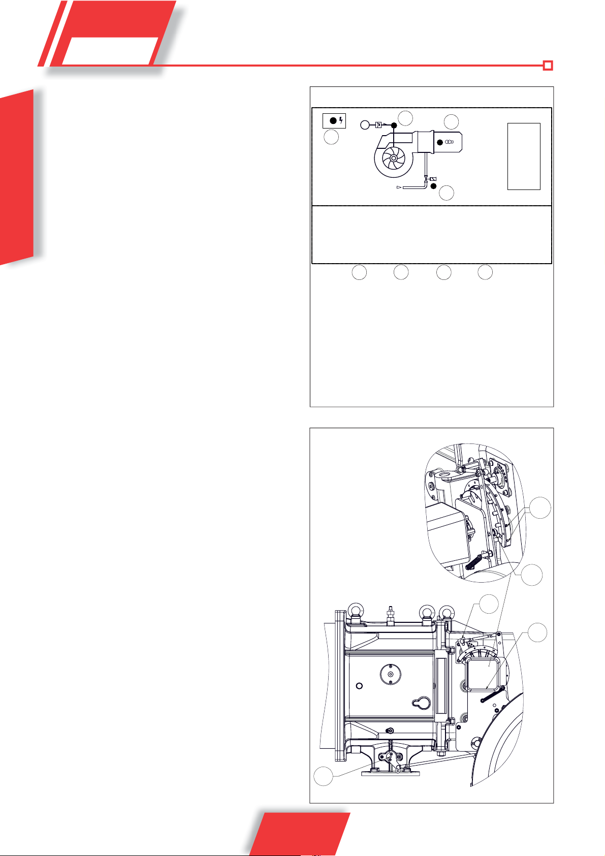
ENGLISH
1 Combustion head
2 Seal
3 Burner connection flange
4 Butterfly gas valve
5 Modulator activation servomotor
6 Synoptic control panel
7 Air pressure switch
8 Air gate unit
9 Electrical panel
10 Hinge
11 Fan motor
12 Intake air conveyor
13
Gas pressure plug on the head
14
Adjusting air/gas modulator
N° 0002471390
A A1 A2 B B1 B2 B5 C C1 D E Ø F Ø R I I1 L Ø M N Ø
TBG 1100 MC 1230 570 660 1000 740 260 310 2030 190 720 451 DN 80 1300 520 520 594 M20 460
DESIGN CHARACTERISTICS
The burner consists of:
• Ventilating part in light aluminium alloy.
• Centrifugal fan for high performances.
• Intake air conveyor.
• Combustion head complete with stainless steel nozzle and
steel flame disc.
• Flame inspection glass
• Three-phase electric motor to run fan.
• Air pressure switch to ensure the combustion air presence.
• Gas train complete with control valve, operating and safety
valves, valve seal control, minimum and maximum pressure
switch, pressure control and gas filter.
0006160025_201305
• Automatic command equipment and burner control according
to European regulation EN298.
• Flame detection by ionisation electrode.
• Control panel including on/off - automatic/manual operation
switches and minimum/maximum selector, operation and lockour indicator lights
• Electric system with protection class IP54.
6 / 28
TECHNICAL FUNCTIONAL CHARACTERISTICS
• Gas burner compliant with European standard EN676.
• Operation with two progressive power stages.
• Combustion head with partial recirculation of combusted gases
with reduced NOx emissions (class II in European standard
EN676).
• Hinge opens both ways to permit convenient access to the mixer
without dismantling the burner from the boiler.
• Minimum and maximum air flow adjustment for first and second
stage by means of modulator with mechanical cam activated
by an electric servomotor.
• Gate closing in pause to prevent any heat dispersion to the flue.
• Valve seal control according to European Standard EN 676.
BURNER CONNECTION TO THE BOILER
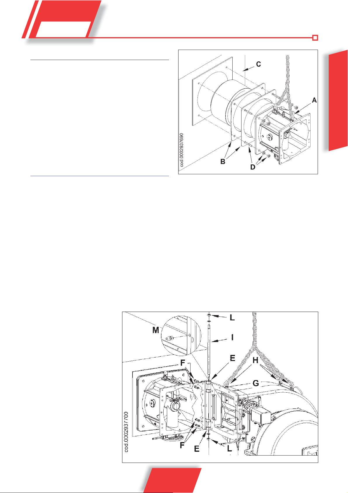
ASSEMBLING THE HEAD UNIT
The combustion head is packaged separately from the body of
the burner.
Anchor the head unit to the boiler door as follows:
• Position the insulating seals on the lung (B).
• Anchor the flange of the lung (A) to the boiler (C) with the stud
bolts, washers and nuts provided (D), moving the lung with
the eye bolts.
Completely seal the gap between the burner sleeve and
the hole in the refractory material inside the boiler door with
suitable material.
FIG.1
ENGLISH
ASSEMBLY THE VENTILATING BODY
The burner hinge can be opened both ways, it is therefore possible
to choose the opening side of the ventilating body
manufactured for hinge installation on the right side. To enable the
maximum opening and so facilitate maintenance operations, it is
recommended to install the hinge on the
side of the burner opposite to the position
where the gas train is installed.
For a correct installation of the ventilating
body, follow the procedure described
below:
• After installing the head unit on the
boiler, assemble the two hinges (E)
on the lung using the 4 screws (F) and
the corresponding washers, without
tightening the screws completely
(hinges are pre-assembled on the
right side, but it is possible to mount
them on the opposite side).
• Place the ventilating body (G)
corresponding to the two hinges
(FIG 2). To handle the ventilating
body, use the specific chains or
ropes anchored to the eyebolts (H).
• Insert pin I, then lock it using the nuts
L and the corresponding washers,
taking care that the abutting surfaces
. The burner is
FIG.2
7 / 28
0006160025_201305
• of the two hinges are perfectly in contact with the corresponding
surfaces of the scroll. Do not tighten the nuts (L) too deeply, as
this may make hinge rotation difficult.
At this stage, avoid tightening the hinge screws (F) completely
and removing lifting chains.
• Tighten the centring pin M (FIG 2) on the fan flange, opposite
to the hinge side.
•
Keeping the chains anchored to the eyebolts, turn the ventilating
ENGLISH
body and place the fan flange in contact with the lung flange,
checking that the pin M is inserted in the corresponding hole
(FIG 3).
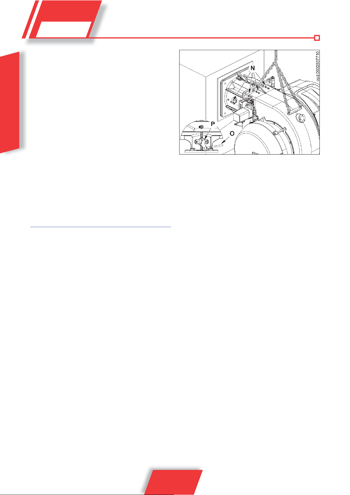
• Close the burner using the screws N and the corresponding
washers. After connecting the ventilating body to the head unit,
proceed with the final tightening of the 4 screws (F) that fasten
the hinges (FIG 2), then unhook the lifting chains or ropes.
• Connect the tie rod (O) to the lever (P) of the gas flow adjusting
throttle (FIG 3).
When it is necessary to open the burner, disconnect the tie
rod O and the connectors of gas solenoid valves.
ELECTRICAL CONNECTIONS
FIG.3
It is advisable to make all electrical connections using a flexible
electrical wire. Electrical lines must be kept away from hot parts.
Make sure that the power line to which the unit will be connected,
has frequency and voltage values suitable for the burner. Make sure
that the main power line, the relative fuse-equipped switch (essential)
and any limiter are capable of withstanding the maximum current
absorbed by the burner.
For more details, see the relevant wiring diagrams for each single
burner.
5
8 / 28
0006160025_201305
50
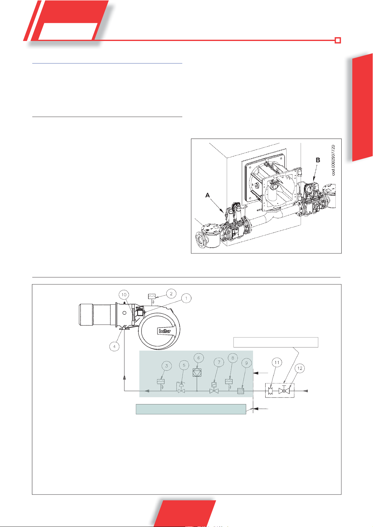
ASSEMBLING THE GAS TRAIN
The EN 676 approved gas train is sold separately from the burner.
The gas train can be assembled in different ways: A and B. Choose
the most rational position for the set-up of the boiler room and the
position in which the gas pipe arrives.
DIAGRAM ILLUSTRATING GAS TRAIN PRINCIPLE
Install a manual on/off valve upstream of the gas valve
according to the layout shown in the diagram illustrating the
gas train principle.
To ensure optimal functioning of the pressure control, it should
be applied to the horizontal pipe after the filter
regulator must be adjusted while operating at the maximum flow
effectively used by the burner. The outgoing pressure must be
adjusted to a value slightly below the maximum possible value
(the value obtained by screwing in the adjustment screw almost
completely); in this case, the outgoing regulator pressure increases
as the adjustment screw is tightened, and decreases as it is
slackened.
. The gas pressure
BASIC DIAGRAM OF BURNER SUPPLY LINE
ENGLISH
29111
GAS TRAIN SUPPLIED BY THE MANUFACTURER
1) Air/gas adjustment servomotor
2) Air pressure switch
3) Maximum gas pressure switch
4) Gas supply modulating control butterfly valve
5) Operating gas valve with pressure regulator
6) Valve seal control device (obligatory for burner with
maximum nominal thermal output over 1200 kW)
7) Safety gas valve
0006160025_201305
RESPONSIBILITY OF THE INSTALLER
8) Minimum gas pressure switch
9) Gas filter
10) Air adjustment gate
11) Vibration-proof joint (not included in supply)
12) Manual shut-off valve (not included in supply)
9 / 28
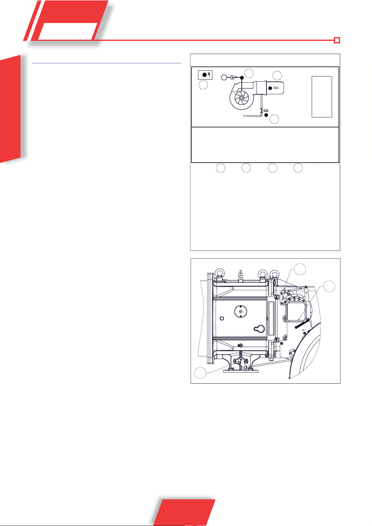
OPERATION DESCRIPTION
The gas train supplied is composed of an ON/OFF safety valve and
a single stage slow opening main valve. The gas flow adjustment in
the first and second stage is carried out by a streamlined butterfly
valve (11) activated by the electric servomotor (9). The movement
of the air shutter (10) is caused by the rotation of the servomotor
(9) through the lever and strap system (3). For the adjustment of
the air damper position according to the power burned in the first
and second stage, consult section: “Starting up and adjustment”. If
ENGLISH
when the main switch (1) is closed, the thermostats are closed, the
voltage reaches the command and control equipment which starts
the burner (2).
This turns on the fan motor for preventilation of the combustion chamber.
At the same time the rotation of the command servomotor (9) which
brings the gas throttle (11) and the air gate (10), through the action of
leverage, in the opening position corresponding to the second flame.
The preventilation phase comes only with the air gate in the second
flame position. At the end of the preventilation phase, the gas throttle
and the air shutter are returned to the ignition position, then the ignition
transformer (4) comes on and the gas valves (5) open.
The presence of the flame, detected by the control device, permits
continuation and completion of ignition, turning off the ignition
transformer. Then passing on to the second stage of power through
the progressive opening of the gas throttle and the air gate at the same
time. At the moment in which the demand for heat from the system
is satisfied, the boiler thermostat will intervene and shut down the
boiler. The air gate through the rotation of the servomotor will reach
the closed position when inactive. In the event that the control device
does not detect the presence of a flame, the control box activates
a “safety shut down” (8) within three seconds of the opening of the
main gas valve. In “safety lock-out” mode the valves are closed again
immediately. To release the equipment from its safety position, press
the release button (8).
MV
3
4
2
GAS
1
1 Main switch on/off
2 Power LED
3 Fan motor thermal relay activation indicator light (if foreseen)
4 Ignition transformer indicator light
5 Gas valves indicator light
6 AUTOMATIC - MANUAL operation selector
7 MIN - MAX power switch
8 Unlocking push-button with lock indicator light
6
5
7
8
sino ttico T BG1100 MC.ai
10 / 28
0006160025_201305
MODULATION OPERATION DESCRIPTION
When the burner is ignited at the minimum flow-rate, if the modulation
probe allows it (adjusted to a temperature or pressure which is
greater than that present in the boiler) the air adjustment servomotor
begins to operate,
- in a clockwise direction the air flow increases,
- in an anti-clockwise direction the air flow decreases,
causing a gradual increase in the combustion air flow and
consequently of the gas, until it reaches the maximum flow setting
of the burner. The burner remains in the maximum flow position until
the temperature or pressure is high enough to trip the modulation
probe, which reverses the rotation of the air adjustment servomotor.
Reverse rotation of the servomotor and consequently a reduction in
gas and air flow take place in short time intervals. By this method,
the modulation system tries to bring the amount of heat supplied
to the boiler in line with the heat that the boiler puts out to service.
The modulation probe installed on the boiler measures any request
variation and automatically adjusts fuel and combustion air supply,
by starting the air/gas adjustment servomotor and increasing or
reducing rotation as necessary. If the limit value (temperature or
pressure) at which the stop device is set (thermostat or pressure
switch) is reached even with gas supply at minimum level, the burner
is shut down by the device.
When temperature or pressure returns below the shut-down device
tripping value, the burner is activated once again according to the
program described in the previous section.
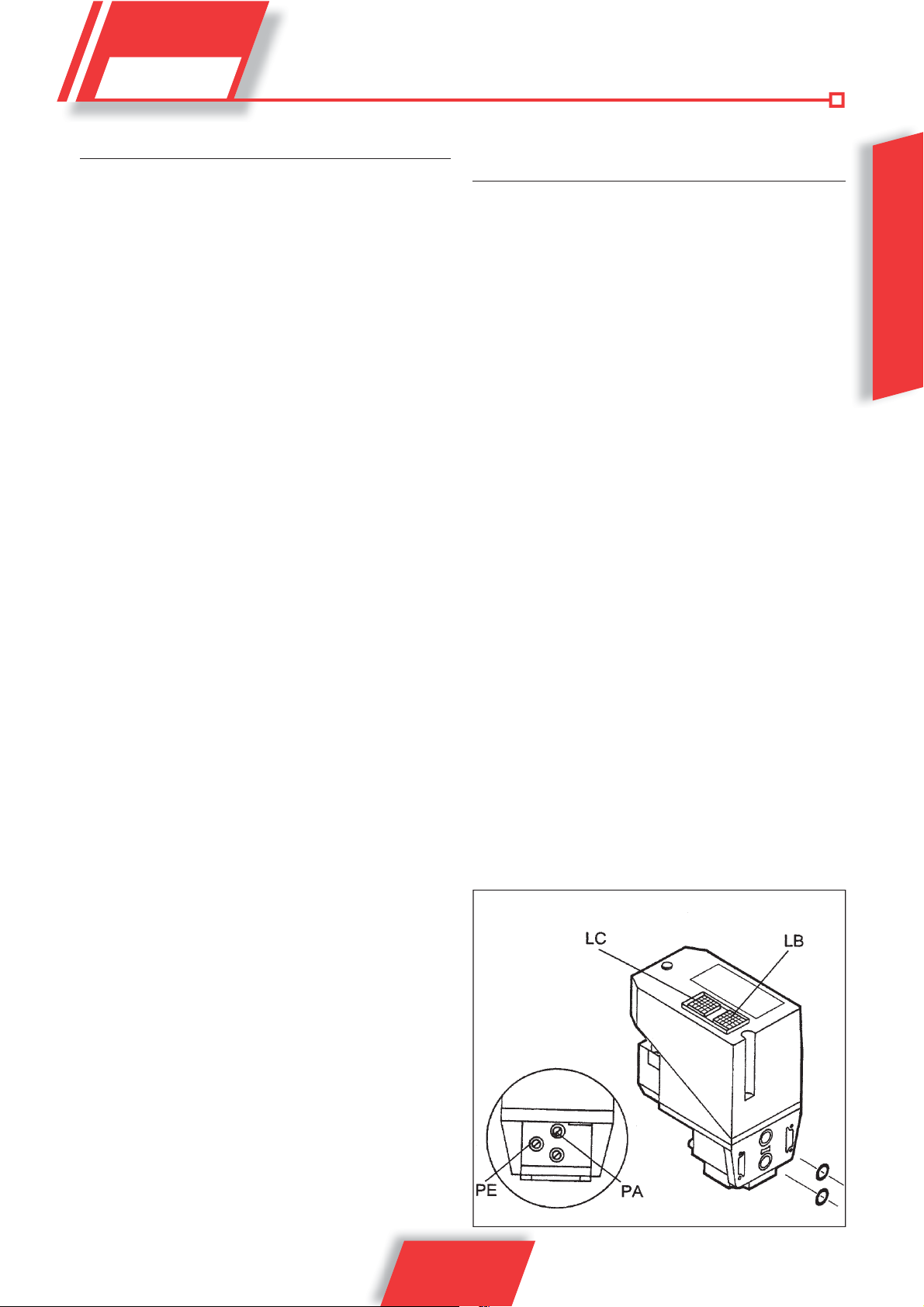
“VPS 504” VALVE TIGHTNESS
CONTROL (IF PRESENT)
It checks the tightness of gas cut-off valves. This check is carried
out as soon as the boiler thermostat authorises burner operation
creating, by means of a membrane pump, an overpressure greater
than the upstream pressure by 20 mbar in the test circuit.
If you wish to carry out a check, place a pressure gauge
corresponding to the PA pressure plug.
If the test circuit has a positive result, the LC authorisation lamp
(yellow) switches on after a few seconds. In order to restart, it is
necessary to unlock the equipment using the LB light button. The
fuse can be accessed using a screwdriver to remove the cover that
is located near the sockets for electrical connection; a spare fuse
is located in the upper part of the tightness control, under the cap.
remark: purchasing the specific kit, it is possible to install the
tightness control on the ramps that are not equipped with it.
ENGLISH
11 / 28
0006160025_201305
VPS504.tif

COMMAND AND CONTROL EQUIPMENT
FOR GAS BURNERS LFL 1...
Command and control equipment for mid and large output blownair burners
(intermittent service *) for 1 or 2 stage burners or for modulating
burners with air pressure monitoring for air shutter control. The
command and control equipment feature the EC mark according
to the Gas and Electromagnetic Compatibility Directive.
ENGLISH
* For safety reasons, it is important to perform a controlled stop
each 24 hours!
As regards the standards
The following LFL1.... features fully comply with the Standards
and ensure an extremely high safety level:
• The flame detector test and false flame test start immediately
after the tolerated post-combustion time. If the valves remain
open, or do not close immediately after the regulation stop, a
shutdown in lock condition is triggered at the end of the allowed
post-combustion time. The tests finish only at the end of the
pre-ventilation time of the next start-up.
• The validity of operation of the flame control circuit is checked
every time the burner starts up.
• The fuel valve control contacts are checked for wear during the
post-ventilation time.
• A built-in fuse in the appliance protects the control contacts from
any overloads that may occur.
of ignition flame on start-up); OPEN at the beginning and MIN
at the end of the pre-ventilation time. If the servomotors fail to
position the air damper in the preset points, the burner does
not start.
• Ionization current minimum value = 6mA
• UV cell current minimum value = 70mA
• Phase and neutral must not be inverted.
• Any assembly position and place (IP40 protection)
As for the burner control
• The equipment allows operation with or without post-ventilation.
• Air shutter controlled command to ensure pre-ventilation at
nominal air flow. Controlled positions: CLOSED or MIN (position
Equipment features
Equipment and
relevant programmer
LFL 1,333 Cyclic relay 3 31.5 6 3 12
Safety time
in seconds
Pre-ventilation time
with open damper (in
seconds)
Pre-ignition (in
seconds)
Post - ignition
in seconds
Time between 1st
fl ame and modulation
in seconds
start
12 / 28
0006160025_201305
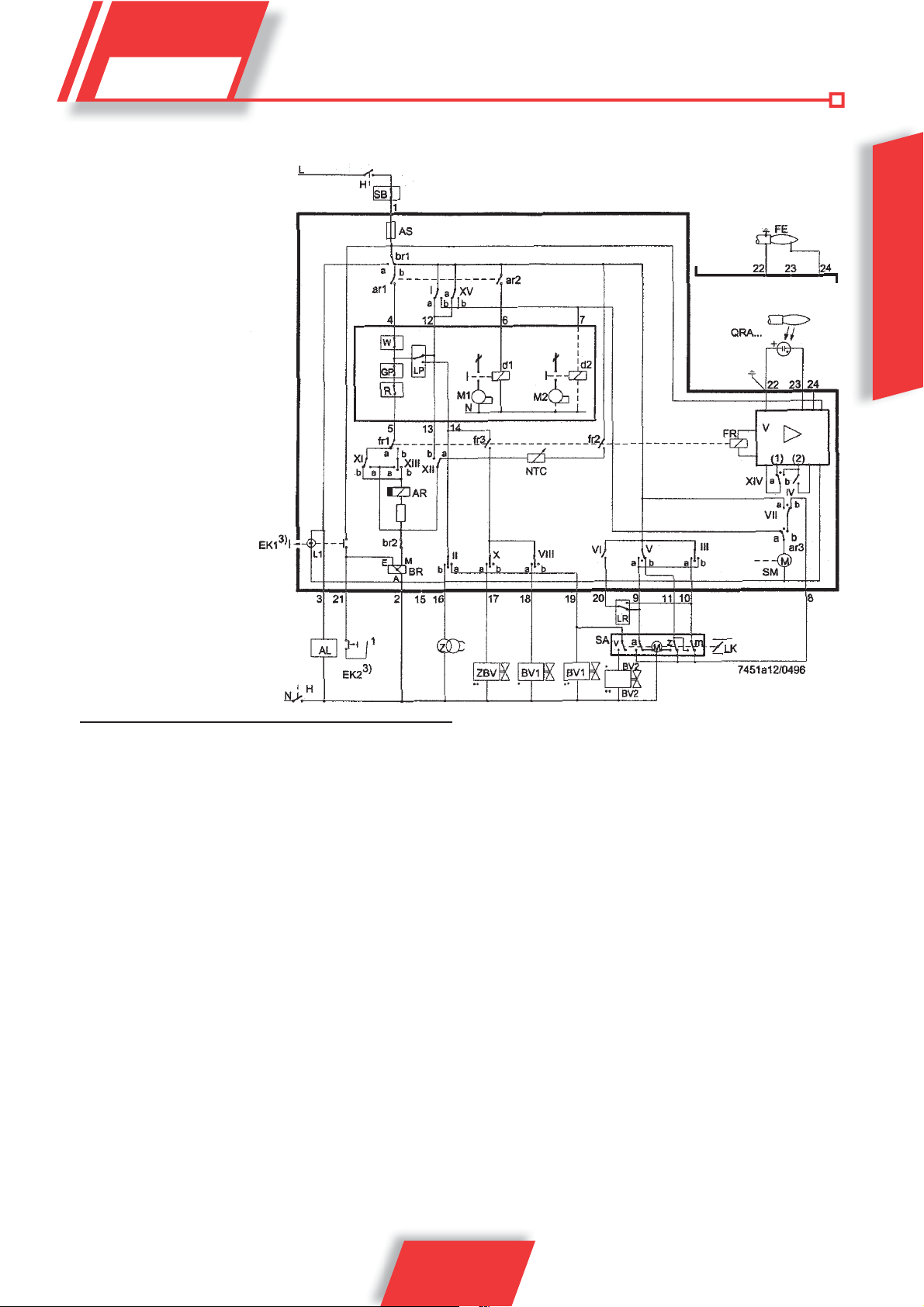
Electric connections
For the safety valve connection
refer to the drawing provided
by the burner manufacturer
ENGLISH
Key
a Limit switch contact for air gate OPEN position
AL Remote lockout warning device (alarm)
AR Main relay (load relay) with «ar» contacts
AS Device fuse
BR Lockout relay with «br» contacts
BV... Fuel valve
bv... Control contact for gas valve CLOSED position
d... Remote switch or relay
EK... Locking button
FE Ionisation current probe electrode
FR Flame relay with «fr» contacts
GP Gas pressure switch
H Main switch
L1 Fault warning light
L3 "Ready for operation" signal
LK Air damper
LP Air pressure switch
LR Load controller
m Auxiliary changeover switch for the air damper’s MIN position
M... Fan or burner motor
NTC NTC resistor
QRA... Probe
UVR Thermostat or pressure switch
RV Fuel valve with continuous regulation
S Fuse
SA Air gate servomotor
SB Safety limiter (temperature, pressure, etc.)
SM Programmer synchronous motor
v In case of servomotor: auxiliary contact for consensus to fuel
valve according to the air damper position
V Flame signal amplifi er
W Limit thermostat or pressure switch
z In case of servomotor: limit switch contact for air damper
CLOSED position
Z Ignition transformer
ZBV Pilot burner fuel valve
• Valid for forced draft burners, with one pipe
•• Valid for pilot burners with intermittent operation
(1) Input for operating voltage increase for UV probe (probe test)
(2) Input for fl ame relay forced excitation during operation test of
the fl ame supervision circuit (contact XIV) and during t2 safety
time (contact IV)
³) Do not press EK for more than 10 s.
13 / 28
0006160025_201305
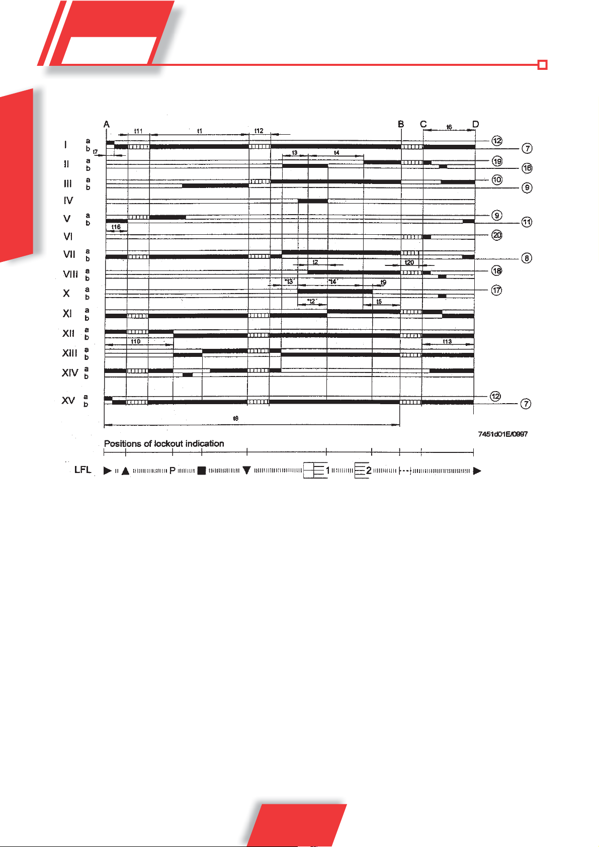
Notes on the programmer
programmer sequence
ENGLISH
Time key
time (50 Hz)
in seconds
31,5 t1 Pre-ventilation time with open air gate
3 t2 Safety time
- t2’ Safety time or fi rst safety time with burners using
pilot burners
6 t3 Short pre-ignition time (ignition transformer on ter-
minal 16)
- t3’ Long pre-ignition time (ignition transformer on terminal 15)
12 t4 Time between the t2' start and the consensus to the
valve on terminal 19 with t2
- t4’ Time between the t2' start and the consensus to the
valve on terminal 19
12 t5 Time between t4 end and the consensus to the
power regulator or the valve on terminal 20
18 t6 Post-ventilation time (with M2)
3 t7 Time between consensus upon start-up and the
voltage to terminal 7 (start delay for fan motor M2)
72 t8 Start-up duration (without t11 and t12)
3 t9 Second safety time for burners using pilot burners
12 t10 Time from start-up to the beginning of the air pres-
sure control without air damper real travel time
t11 Damper opening travel time
t12 Damper travel time in low fl ame position (MIN)
18 t13 Allowed post-combustion time
6 t16 Starting delay of consensus to air damper OPEN-
ING
27 t20 Time up to automatic closure of the programmer
mechanism after burner start-up
NOTE: With voltage at 60 Hz the times are reduced by nearly
20%.
14 / 28
0006160025_201305

t2´, t3´, t4´:
Such time intervals are valid only for burner command and control
equipment of series 01, i.e. LFL1.335, LFL1.635, LFL1.638. They do
not apply to burners of the series 02 since they have a simultaneous
activation of the X and VIII cams.
Operation
The drawings above show both the connection circuit and the
sequencer mechanism control program.
A Start-up confirmation by means of thermostat or the installation
pressure switch “R”.
A-B Start-up program
B-C Normal burner operation (on the basis of “LR” power regulator
control commands)
C Stop controlled by “R”
C-D Programmer return to start-up position A, post-ventilation.
During periods of burner inactivity, only the 11 and 12 control
outputs are powered and the air damper is CLOSED by the "z"
limit switch of the relevant servomotor. During the probe test
and the false flame test, also the flame supervision circuit is
powered (terminals 22/23 and 22/24).
Safety standards
on, any missing air pressure indication triggers a
shutdown!
Lock-out stop due to malfunction of the flame detection circuit.
Start-up sequence stops, because the position signal for
low flame was not sent to terminal 8 by auxiliary switch “m”.
Terminals 6, 7 and 15 remain live until fault removal!
1 Lock-out stop, due to lack of flame signal at the end of the
first safety time.
2 Lock-out stop, because no flame signal was received at the
end of the second safety time (main flame signal with pilot
burners at intermittent operation).
Lock-out stop, due to lack of flame signal during burner
operation.
If a shutdown occurs between start-up and pre-ignition with no
symbol, usually the cause is a premature flame, i.e. faulty, flame
signal caused for example by the self-ignition of an UV pipe.
ENGLISH
• In association with the use of QRA…, grounding of terminal 22
is compulsory.
• The power cables must conform to existing national and local
standards.
• LFL1… is a safety device, and it is therefore forbidden to open
it, tamper with it or modify it!
• The LFL1… device must be completely insulated from the mains
before carrying out any operations on it!
• Check all the safety functions before activating the unit or after
replacing a fuse!
• Provide protection against electric shock on the unit and all
electric connections.
• During use and maintenance, take care to prevent any infiltration
of condensation water on the controls.
• Electromagnetic emissions must be verified during use.
Control program in case of stopping and indication of stop
position
As a rule, in the event of any kind of stop, the fuel flow is immediately
cut off. At the same time both the programmer and the switch position
indicator remain in the same position. The symbol on the indicator
reading disk indicates the fault type.
No start-up, due to failure of a contact or lock-out stop to
close during or at the end of the command sequence because
of external lights (for example: flames not extinguished, leak
of the fuel valve, defects in the flame control circuit, etc.)
Shutdown indications
a-b Start-up program
b-b’ “Trips” (without contact confi rmation)
b(b’)-a Post-ventilation program
Start-up sequence stops, because the OPEN signal was not
sent to terminal 8 by limit switch contact “a”. T erminals 6, 7 and
15 remain live until fault removal!
P Shutdown, due to no air pressure signal. From this moment
0006160025_201305
LFL1..., series 01LFL1..., series 02
15 / 28
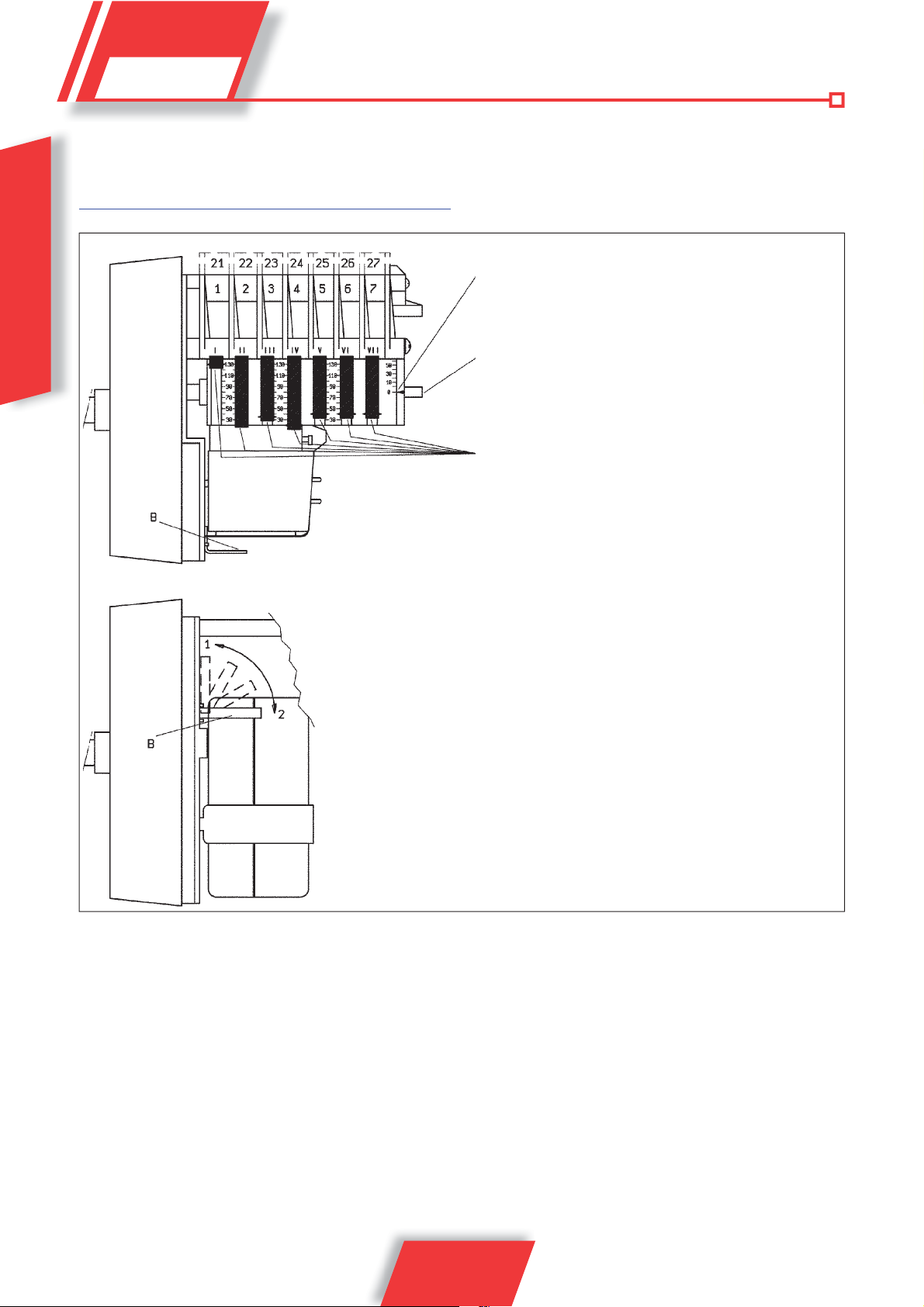
DETAILS OF THE MODULATION
CONTROL MOTOR SQM 10 AND SQM
20 FOR REGULATION OF CAMS
Reference index
ENGLISH
0002937530.tif
Camshaft
Adjustable cams
B = On and off lever for motor - camshaft coupling.
- Position 1 = disabled
- Position 2 = enabled
I MAXIMUM AIR OPENING (130°)
II TOTAL AIR CLOSURE (BURNER OFF) (0°)
III IGNITION AIR OPENING (CAM III MAXIMUM) (35°)
IV MINIMUM AIR OPENING (LOWER THAN CAM IV) (15°)
To modify the adjustment of the 3 cams used, use the respective red rings (I - II - III....).
The index on the red ring indicates on the respective reference scale the rotation angle
set for each cam.
16 / 28
0006160025_201305
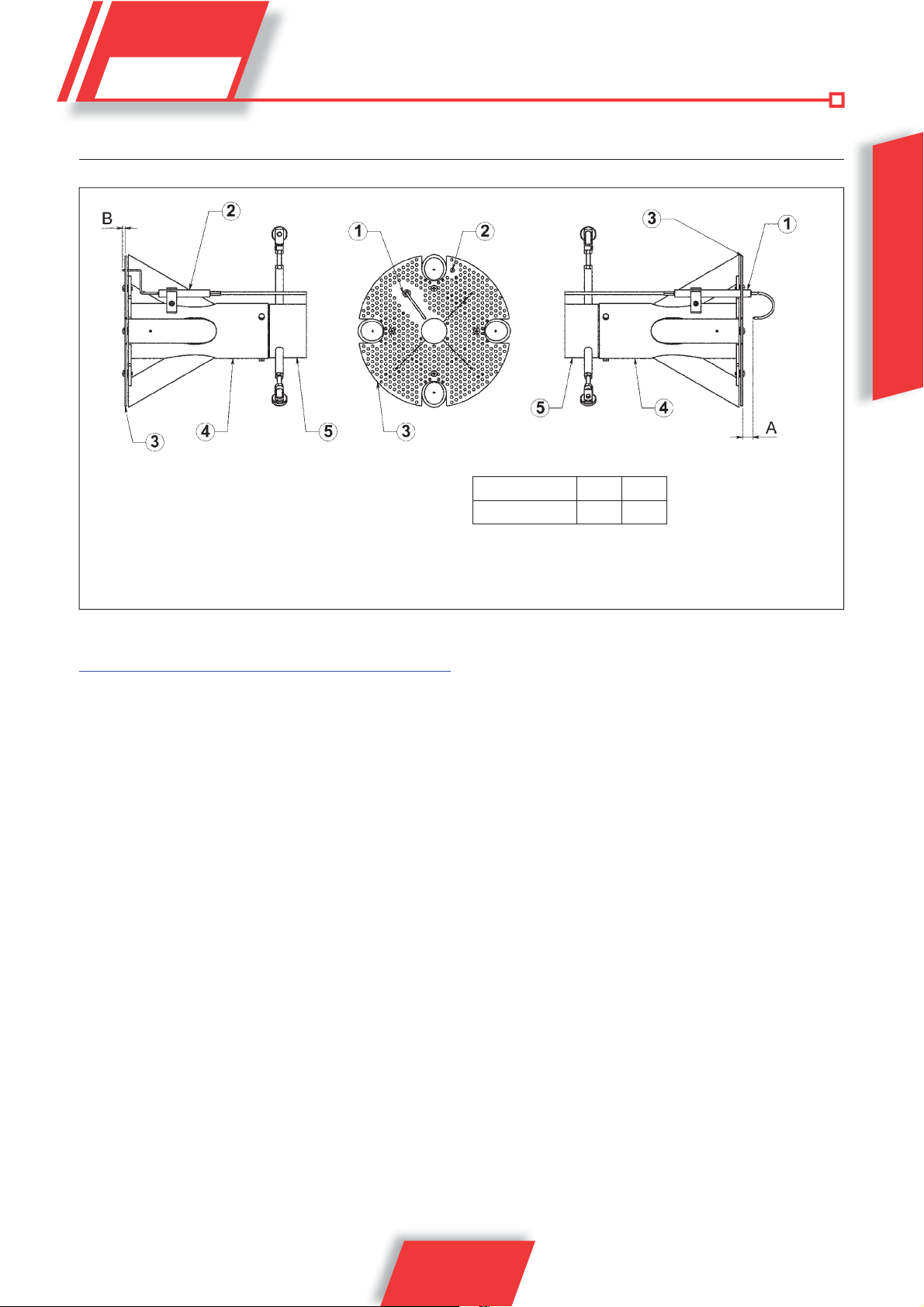
DIAGRAM ILLUSTRATING REGULATION OF COMBUSTION HEAD AND DISTANCE OF ELECTRODE DISK
0002937680
ENGLISH
1) Ionising electrode
2) Ignition electrode
3) Flame disk
4) Mixer
5) Gas delivery pipe
IGNITION AND ADJUSTMENT
Instructions for manual burner operation
Combustion may be checked throughout the entire burner operating
range by controlling the equipment manually.
Set the switch (6) to manual position (MAN).
Use the switch (7) to increase or decrease gas and air.
After completing the check, set the switch (6) to automatic position
(AUT).
• Check that there is water in the boiler and that the system’s
gate valves are open.
• Make absolutely sure that the products of combustion can be
released freely (boiler and flue dampers must be open).
• Check that the voltage of the electrical line corresponds to that
required by the burner. Electrical connections (motor and main line)
must be prepared for the voltage available. Check that all electrical
connections made on-site are performed correctly as shown in
our wiring diagram. To prevent operation of the second flame,
open the second stage thermostat circuit.
• Adjusting power upon first start-up
- Position the ignition gas flow adjustment cam on the electric
servomotor to an opening angle of 35° (0002937530). If it
exists, open the safety valve flow regulator completely.
- Now switch on the switch (1). The command equipment
thus receives voltage and the programmer causes the
burner to switch on as described in chapter “OPERATION
DESCRIPTION”. During preventilation, make sure that the air
pressure control switch changes its status (from the closed
position without pressure measurement to the closed position
AB
TBG 1100 MC 20 5
with pressure measurement). If the air pressure switch does
not detect sufficient pressure, the ignition transformer (4) is not
switched on, nor are the gas valves (5) and so the equipment
is stopped in “lock-out” (8) mode.
- On first switching on repeated “lock outs” may occur due to
the following reasons:
- The gas piping has not been vented correctly and so there is
not enough gas to provide a stable flame.
- “Lock out” with flame presence could be caused by flame
instability in the ionisation area, due to an incorrect air/gas
ratio.
- Correct the air flow acting on the screw(s)
(12), corresponding to the bearing (13).
- in a clockwise direction the air flow increases,
- in an anti-clockwise direction the air
flow decreases.
Proceed with the regulation of the air until a position is found
which allows ignition without resulting in blocking.
- It may occur that the ionisation current is disturbed by the
discharge current of the ignition transformer (the two currents
have a common path on the burner’s “mass”) so the burner
locks out due to an insufficient ionisation. Invert the supply
(230V side) of the ignition transformer.
- This problem may also be caused by an insufficient “ground
connection” to the burner’s casing.
• Adjusting second stage power.
After completing first ignition adjustment, turn the switch (7)
towards
17 / 28
0006160025_201305
• the maximum (MAX) so as to get the maximum air and gas delivery.
Ensure that the gas flow adjustment cam in the second
stage of the electric servomotor is positioned at 130°.
- To regulate the gas flow operate the valve pressure regulator .
Consult the instructions related to the installed gas valve
model. Avoid keeping the burner running if the heating
capacity is greater than the maximum amount allowed for
the boiler, to avoid damaging it.
- For adjusting the air flow rate, operate on the screws (12),
ENGLISH
correct the rotation angle of the air gate in the suitable position
to guarantee the right quantity for the power burned.
- Check the combustion parameters with appropriate
instruments (C0
max= 10%, O2 min=3%, CO max=0,1%)
2
• Adjusting first stage power.
After having adjusted the burner in the second stage, put the
burner into the first stage. Turn switch (7) towards the minimum
(MIN) without varying the adjustment of the gas valve already
performed.
- Adjust the gas flow in the 1
st
stage to the desired value using
the adjustment cam IV for servomotor minimum output (see
0002937530).
- If necessary, correct the combustion air supply adjusting the
screw(s) (12).
- Check the combustion parameters in the 1
appropriate instruments (C02 max= 10%, O2 min=3%, CO
max=0,1%)
• Adjusting the flow rate for ignition
- Once adjustment of the first stage has been carried out,
the burner needs to be switched off and check that ignition
occurs properly. If necessary, it is possible to optimise burner
adjustment in the start-up phase proceeding as follows:
- Adjust the gas flow in the start-up phase, using the adjustment
cam III for ignition output adjustment (see 0002937530). It is
often advisable to set cam III at a slightly higher angle than
cam IV for first stage.
- If necessary, correct the combustion air supply adjusting the
screw(s) (12).
• The air pressure switch prevents the opening of the gas valves
if the air pressure is not the foreseen one. The pressure switch
must therefore be adjusted to intervene closing the contact
when the air pressure in the burner reaches a sufficient
value. If the air pressure switch does not detect pressure
greater than that calibrated, the equipment runs through
its cycle but does not switch on the ignition transformer and
does not open the gas valves and so the burner “locks-out”.
To ensure correct operation of the air pressure switch you
must, with burner on and in 1
st
stage, increase its adjustment
until it is triggered and immediately “locks-out” the burner.
Adjust the setting of the pressure switch to a level slightly below
the actual air pressure detected in first stage operation. Release
the burner and check that it starts up correctly.
• The gas control pressure switch (minimum) prevents burner
st
stage with
MV
3
4
2
GAS
1
1 Main switch on/off
2 Power LED
3 Fan motor thermal relay activation indicator light (if foreseen)
4 Ignition transformer indicator light
5 Gas valves indicator light
6 AUTOMATIC - MANUAL operation selector
7 MIN - MAX power switch
8 Unlocking push-button with lock indicator light
6
5
7
8
sino ttico T BG1100 MC.ai
18 / 28
0006160025_201305
• operation when gas pressure is not the foreseen one. The
minimum pressure switch must make use of the contact which
is closed when the pressure switch detects a pressure higher
than its own setting. Therefore the adjustment of the minimum
pressure switch must be carried out when the burner is started
up, in accordance with the pressure that is found from time to
time. The triggering (opening of the circuit) of any of the pressure
switches when the burner is running (flame on) causes the
burner to stop immediately. When first switching on the burner
it is essential to check that it works properly.
• Check the triggering of the ionisation electrode by disconnecting
the cable of terminal 24 of the terminal board and switch on the
burner. The equipment must run through its cycle completely
and, three seconds after the ignition flame has formed, “lock-out”.
• Check the efficiency of the boiler pressure switches or
thermostats (they should shut down the burner when triggered).
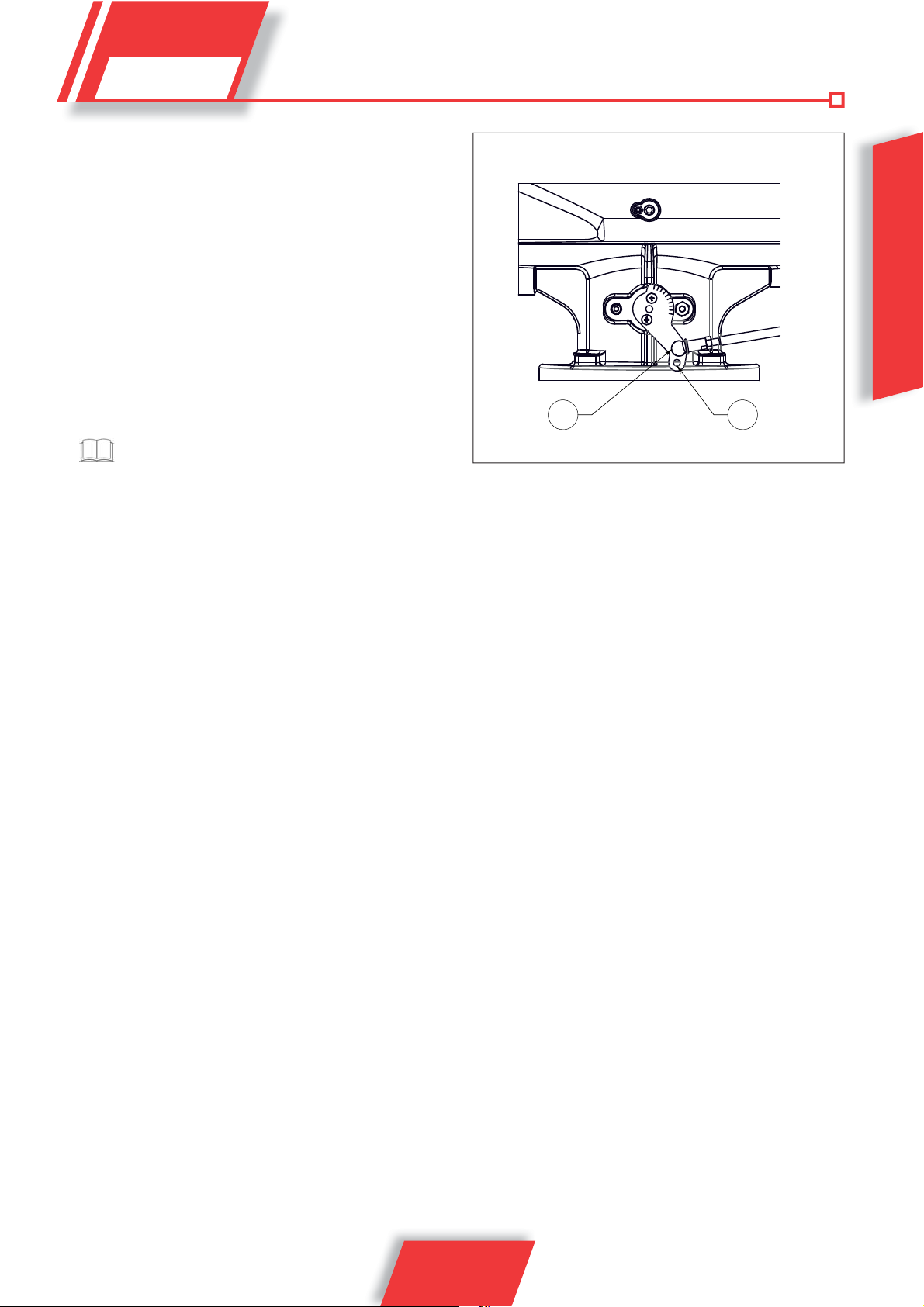
Once the adjusting operations are completed, visually check
that the thin plate on which the bearing acts has a progressive
profile. Using the special instruments check also that in the
passage from the 1
do not move too much away from the optimal values.
The butterfly valve for gas adjustment is factory set at lever
position "1". If it is necessary to decrease the adjustment
range (opening angle of the gas butterfly valve), place the
joint to position “2”.
st
to the 2nd stage combustion parameters
ENGLISH
19 / 28
0006160025_201305

AIR PRESSURE SWITCH OPERATION
DESCRIPTION
The air pressure switch is used to lock the equipment if air pressure
is not at the expected value. The pressure switch must be set to
close the normally open contact, when the air pressure in the burner
reaches a suffi cient value.
T o verify that the air pressure switch is operating correctly , con while
the burner is ignited at its minimum setting, while the burner is ignited
ENGLISH
at its minimum setting. Reset the burner by pushing the appropriate
button and readjust the pressure switch to an adequate value to
detect the existent air pressure during the pre-ventilation phase.
GAS PRESSURE SWITCH OPERATION
DESCRIPTION
The pressure switches for checking gas pressure (minimum
and maximum) prevent the burner from operating when gas pressure is not between the expected ranges. The specifi c function of
the pressure switches clearly reveals that the pressure switch for
controlling minimum pressure uses the NO contact (normally open)
which is closed when the pressure switch detects a pressure value
above the value it is set to, while the pressure switch for controlling
maximum pressure uses the NC contact (normally closed) which is
closed when the pressure switch detects a pressure lower than the
value it is set to. The minimum and maximum gas pressure switches
must be set when testing the burner, on the basis of the pressure
measured in each case. The pressure switches are connected in
a way in which tripping (opening the circuit) of one of the pressure
switches when burner is working (fl ame on), will shut down the
burner immediately.
Adjustment before switching on the burner:
set the minimum pressure switch to the lowest setting on the scale,
set the maximum pressure switch to the highest setting on the scale.
Adjustment after burner calibration:
With the burner at the maximum delivery, regulate the pressure
switch for minimum pressure by increasing the regulation value
until the burner shuts down, read the value on the regulation ferrule and set it to a value diminished by 5 mbar. With the burner off,
regulate the pressure switch for maximum pressure, diminishing
the regulation value until the NC (normally closed) contact opens.
Read the value on the regulation ferrule and set it to a value increased by 5 mbar.
in case only one pressure switch is installed on the gas train
it must be a pressure switch for minimum pressure.
press aria001
20 / 28
0006160025_201305
MAINTENANCE
The burner does not require any particular maintenance, it is recommended at least to carry out the following operations at the end of
the heating season:
• Clean the air shutters, the air pressure switch with pressure
intake and the pipe.
• Check the conditions of the ionisation electrode.
• Have the boiler cleaned and, if necessary, also the chimney by
specialized personnel (stove repairer); a clean boiler is more
efficient, lasts longer and is quieter.
• Periodically check that the gas filter is clean for gas burners.
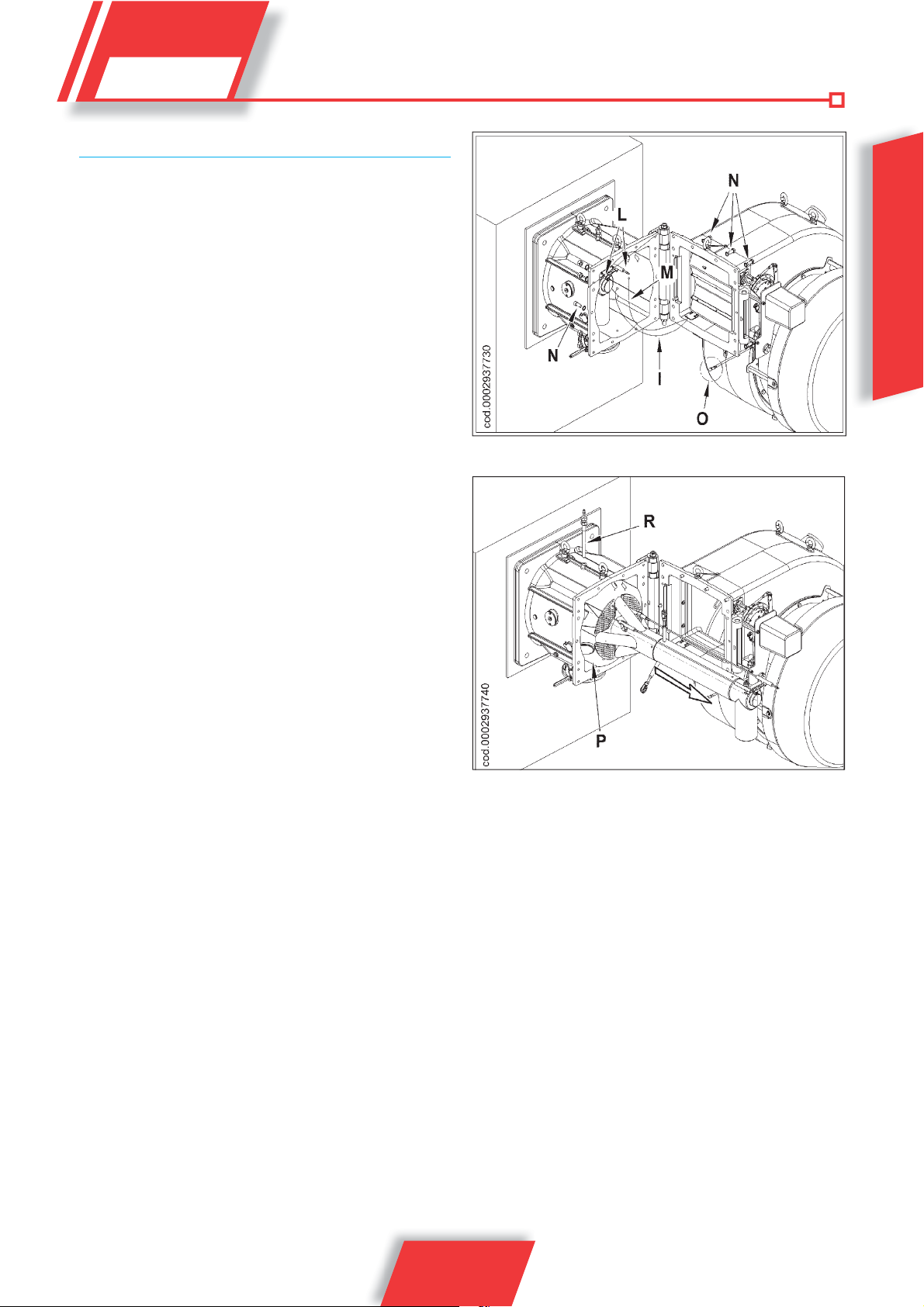
• In order to clean the combustion head, its components must
be disassembled. Be careful during the reassembly operations
to exactly centre the gas diffuser with regard to the electrodes,
making sure that they are not earthed, which would result in the
locking of the burner. It should also be checked that the ignition
electrode spark occurs only between the electrode itself and the
perforated sheet disk.
Periodically test combustion gases and check that the emissions
values are correct.
Check that all components of the combustion head are in good
condition, have not been deformed by high temperatures and are
free from impurities or deposits deriving from the installation environment or from poor combustion. If it is necessary to clean the
combustion head, take out its components according to the procedure described below:
• unscrew the anchoring screws (N), disconnect the tie rod (O)
and open the ventilating body;
• pull out the ignition (I) and ionization cables (M) from their
electrode terminals (L);
• unscrew the screw (R) from the lung (P);
• pull out the entire mixer unit in the direction shown by the
arrow. Having completed the maintenance work, replace the
combustion head, following in reverse order the operations
described above, after having checked the correct position of
the electrodes of ignition and of ionization (see 0002937680).
ENGLISH
21 / 28
0006160025_201305

IONISATION CURRENT MEASUREMENT
The minimum ionisation current needed to run the equipment is 6
μA. The burner flame generates a significantly higher current, which
usually does not require any control by the equipment.
Should the ionisation current need to be measured, a microammeter
must be connected in series to the ionisation electrode lead by
opening the connector “C”, see wiring diagram.
LFL 1.3xx
24
M
-
+
ionizzazione LFL.ai
FE
ENGLISH
C
22 / 28
0006160025_201305

HOW TO FIND THE CAUSES OF IMPROPER OPERATION OF TWOSTAGE GAS BURNERS AND HOW TO RECTIFY THEM
PROBLEM POSSIBLE CAUSE SOLUTION
Appliance locked out due to no flame
(red light lit). The fault is in the flame
control device.
The burner goes into “lock-out”, gas
flows, but there is no flame (red light on).
Fault in ignition circuit.
The burner goes into “lock-out”, gas
flows, but there is no flame (red light on).
• Disturbance to ionization current from the
ignition transformer.
• Flame sensor (ionisation probe)
inefficient.
• Flame sensor (ionisation probe) position
incorrect.
• 4) Ionization probe or relative earth cable.
• Electrical connection cut-off by flame
sensor.
• Inefficient draught or fumes passage
blocked.
• Flame disk or combustion heads dirty
or worn.
• Equipment fault.
• No ionization.
• Fault in ignition circuit
• Ignition transformer cable discharges
to earth.
• Ignition transformer cable disconnected.
• Ignition transformer faulty.
• The distance between electrode and
earth is incorrect.
• Isolator dirty, so electrode
discharges to earth.
• Air/gas ratio incorrect.
• Gas pipe has not been properly bled of
air (in the case of first ignition).
• The gas pressure is insufficient
orexcessive.
• Air flow between disk and head too
narrow.
• Invert the ignition transformer power supply
(230V side) and check using an analogue
micro-ammeter.
• Replace flame sensor
• Correct the position of the flame sensor,
and then check its efficiency by connecting
the analogue micro-ammeter.
• Check visually and using the instrument.
• Restore the connection.
• Ensure that the boiler fumes passage and
chimney connection are free.
• Visually check and replace, if necessary.
• Replace it.
• If the “earth” of the equipment is not
efficient, do not check the ionization
current. Check the efficiency of the “earth”
at the terminal concerned in the equipment
and at the “earth” connection of the electric
system.
• Check the ignition transformer power
supply (230V) and high voltage circuit
(electrode to earth or isolator broken under
locking terminal).
• Replace it.
• Connect it.
• Replace it.
• Position at the correct distance
• Clean or change the isolator or electrode.
• Correct the air/gas ratio (there is probably
too much air or very little gas)
• Bleed the gas pipe again, taking great care.
• Check the maximum gas pressure value at
the time of ignition (use a waterpressure
gauge, if possible).
• Adjust the disk/head opening.
ENGLISH
23 / 28
0006160025_201305
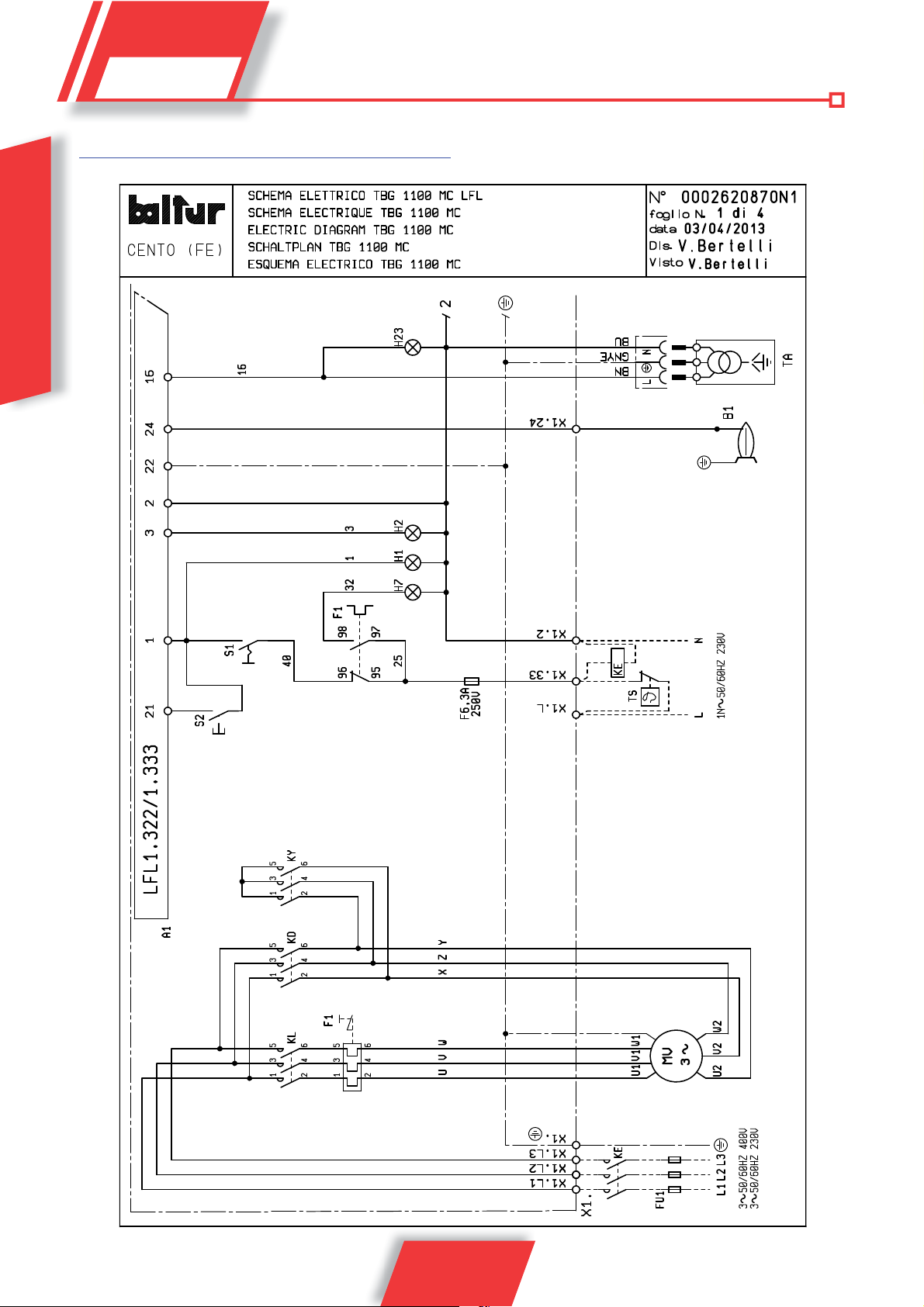
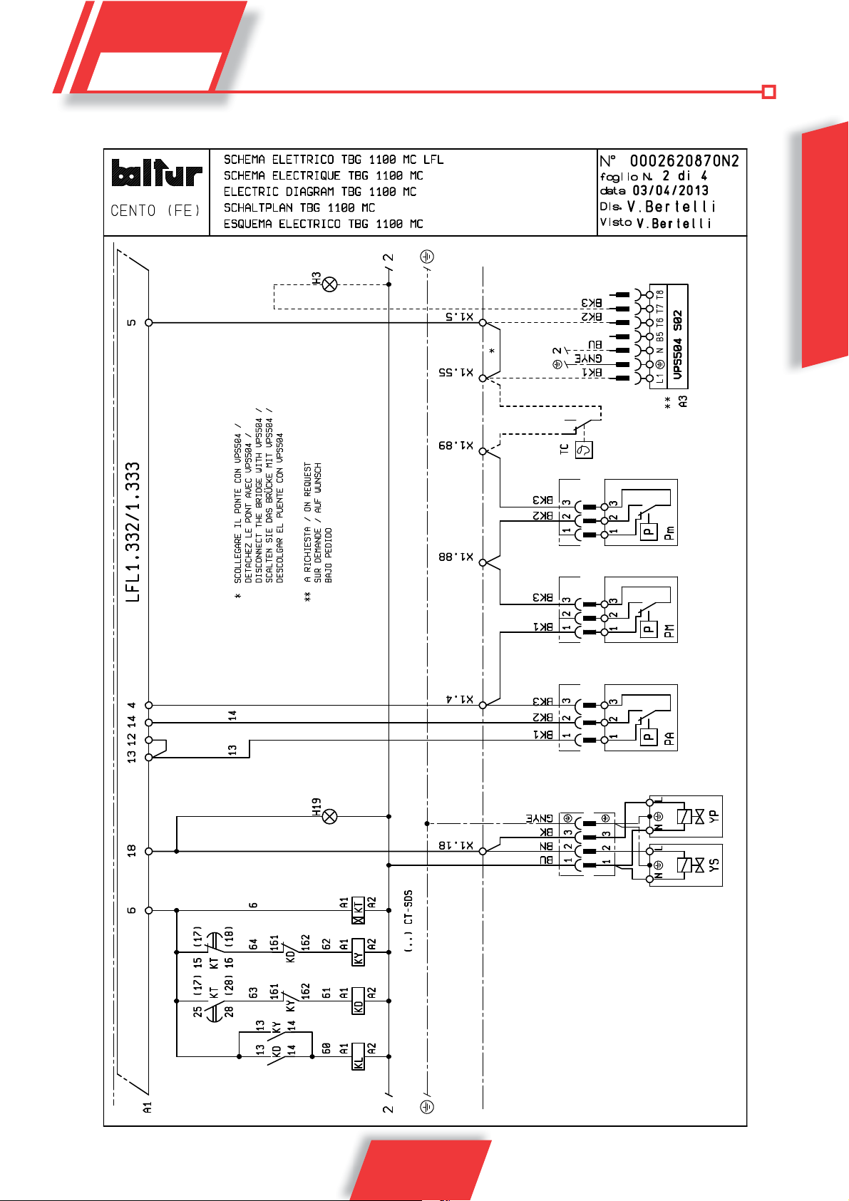
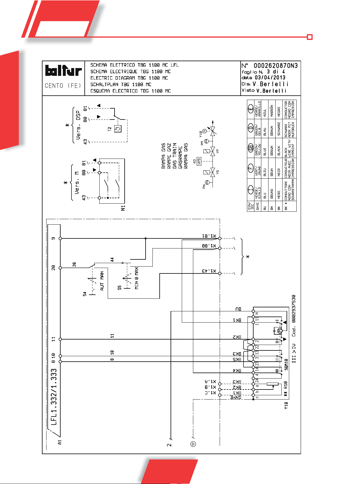
WIRING DIAGRAM
ENGLISH
24 / 28
0006160025_201305
ENGLISH
* DISCONNECT THE JUMPER WITH VPS504
** OPTIONAL
25 / 28
0006160025_201305
ENGLISH
GAS TRAIN
26 / 28
0006160025_201305
** OPTIONAL ITEM
IT
A1 EQUIPMENT
A3 VALVE SEAL CONTROL
B1 IONISATION ELECTRODE
F1 THERMAL RELAY
FU1 FUSES
H1 OPERATION INDICATOR LIGHT
H19 MAIN VALVES ON LIGHT
H2 LOCK INDICATOR LIGHT
H23 TRANSFORMER LAMP
H3 LDU11 SHUTDOWN WARNING LIGHT
H7 FAN MOTOR THERMAL RELAY BLOCK LAMP
KD TRIANGLE CONTACTOR
KE EXTERNAL CONTACTOR
KL LINE CONTACTOR
KT TIMER
KY STAR CONTACTOR
MV MOTOR
N1 ELECTRONIC REGULATOR
P M MAXIMUM PRESSURE SWITCH
PA AIR PRESSURE SWITCH
Pm MINIMUM PRESSURE SWITCH
R10 POTENTIOMETER
S1 START/STOP SWITCH
S2 RELEASE BUTTON
S4 AUT-MAN SELECTOR
S5 MIN-MAX SWITCH
T2 2
TA IGNITION TRANSFORMER
TC BOILER THERMOSTA T
TS SAFETY THERMOSTAT
X1 BURNER TERMINAL
Y10 AIR SERVOMOTOR
YP MAIN SOLENOID VALVE
YS SAFETY SOLENOID VALVE
nd
STAGE THERMOSTAT
ENGLISH
DIN / IEC EN
GNYE GREEN / YELLOW
BU BLUE
BN BROWN
BK BLACK
BK* BLACK CONNECTOR WITH OVERPRINT EN A1
CONTROL BOX B1
0006160025_201305
27 / 28

ENGLISH
28 / 28
0006160025_201305
 Loading...