

baltur COMIST 72 DSPGM, COMIST 180 DSPGM, COMIST 122 DSPGM, COMIST 250 DSPGM, COMIST 300 DSPGM Instruction
Page 1
- Instruction for burners model
COMIST 72 DSPGM
COMIST 122 DSPGM
en
COMIST 180 DSPGM
COMIST 250 DSPGM
COMIST 300 DSPGM
- The works on the burner and on the system have to
be carried out only by competent people.
- Read carefully the instructions before starting the
burner and service it.
- The system electric feeding must be disconnected
before starting working on it.
- If the works are not carried out correctly it is
possible to cause dangerous accidents.
Edition
2003/11
Cod. 0006080115
Page 2

Dichiarazione del Costruttore
Dichiariamo che i bruciatori di gas, gasolio, olio combustibile e misti (gas/gasolio oppure gas/olio combustibile)
sono da noi prodotti a regola d’arte in conformità alle Norme CE - CEI - UNI vigenti al momento della costruzione.
• La BAL TUR garantisce la certificazione “CE” sul prodotto solo se il bruciatore viene inst allato con la ramp a
gas “CE” fornita dalla BALTUR e con accessori di linea gas certificati “CE” (forniti su richiesta).
NOTA : la presente dichiarazione non è valida, relativamente alla Norma CE oppure UNI, per i bruciatori di gas e per la
parte gas dei bruciatori misti (gas/gasolio oppure gas/olio combustibile) quando, gli stessi, ci vengono ordinati non
conformi alla Norma CE oppure UNI, perché destinati ad uso speciale, non previsto nelle norme sopra indicate.
Manufacturer’s declaration
We hereby declare that our gas, light oil, heavy oil, and combination (gas/light oil or gas/heavy oil)
burners are manufactured in conformance with current CE, CEI and UNI standards.
• BALTUR guarantees the “CE” certification provided that the burner is coupled to the “CE” gas train supplied
by BAL TUR and the “CE” gas line accessories (on request).
NOTE: this declaration is not valid with regard to EC or UNI Standards for gas burners or the gas p art of
duel-fuel burners (gas/light oil or gas/heavy oil) when such burners have been ordered in non-compliance
with the EC St andard or It alian UNI Standard because they are to be used for special purposes not provided
for in the above-mentioned standards.
Declaración del fabricante
Declaramos que la empresa fabrica los quemadores de gas, gasóleo, fuel y mixtos (gas/gasóleo o
gas/fuel) ajustándose a las Normas CE - CEI - UNI vigentes en el momento de su fabricación.
• La firma “BALTUR” garantiza la certificación “CE” sombre el producto sólo si el quemador viene instalado
con la rampa gas “CE” suministrada por la “BALTUR” misma y con los accesorios de linea gas
certificados “CE” (suministrables a pedido).
NOTA: la presente declaración no tiene validez, respecto a la Norma CE o UNI, para los quemadores de
gas y para la parte de gas de los quemadores mixtos (gas/gasóleo o gas/fuel) cuando, los mismos, se
piden no conformes a la Norma CE o a la norma italiana UNI, porque están destinados a un uso especial,
no previsto en las normas arriba mencionadas.
Déclaration du constructeur
Nous déclarons que les brûleurs à gaz, fioul, fioul lourd et mixtes (gaz/fioul ou gaz/fioul lourd) sont
produits selon les règles de l’art, conformément aux Normes CE – CEI – UNI en vigueur au moment de la
fabrication.
• La BALTUR garantit la certification “CE” seulement si les brûleur sont installé avec les rampes de gaz “CE”
produites par la BALTUR et les accessoires de ligne gaz “CE” (fournis sur demande).
NOTE: la présente déclaration n’est pas valable, correspondante à la Norme CE ou bien UNI, pour les
brûleurs à gaz et pour la partie gaz des brûleurs mixtes (gaz/fioul ou bien gaz/fioul lourd) lorsque, ces
derniers, nous sont commandés sans être conformes à la Norme CE ou bien à la norme italienne UNI, parce
qu’ils sont destinés à une utilisation spéciale qui n’est pas prévue par les normes indiquées ci-dessus.
Herstellererklärung
Wir erklären, dass die Gas-, Heizöl-, Schweröl- und Wechselbrenner (Gas/Heizöl oder Gas/Schweröl)
von uns fachgerecht und in Übereinstimmung mit den zum Zeitpunkt der Fertigung geltenden Normen CE CEI - UNI hergestellt wurden.
• Die “CE”-Zertifizierung der von BALTUR hergestellten Produkte ist nurin Verbindung mit einer von BALTUR
gelieferten CE-Gasarmatur und unter Verwendung von CE-zertifizierten Bauteilen in der Gaszufürhrung gültig.
HINWEIS: Die vorliegende Erklärung im Hinblick auf die EU- oder UNI-Normen ist nicht gültig für
Gasbrenner und für den Gasteil von Wechselbrennern (Gas/Öl oder Gas/Schweröl), wenn solche bei uns
ohne Konformität mit den EU-Normen oder mit der italienischen Norm UNI bestellt werden, weil sie eine für
spezielle Verwendung bestimmt sind, die von den oben genannten Normen nicht vorgesehen ist.
L' Amministratore delegato
Dott. Riccardo Fava
2
Page 3
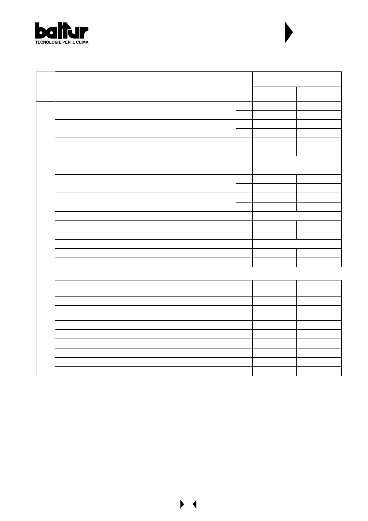
CARA TTERISTICHE TECNICHE
Ó
R
TECHNICAL DA T A
CARACTIRÍSTICAS TÉCNICAS
N° 0002570030
Rev.
CARATTERIS T I CHE TECNICHE / T ECHNICAL DAT A
CARACTERÍST ICAS T ÉCNICAS / T ECHNIS CHE DAT EN
POTENZA TERMICA / THERMIC CA PACITY /
POTENCIA TÉRMICA / HEIZLEISTUNG
PORTATA / FLOW RA TE / CAUDAL / DURCHSA TZ
PRESSIONE MIN.(*) / MIN. PRESSURE (*) /
PRESIÓN META NO MÍN. (*) / DRUCK MIN. (*)
METANO /
NATURAL GAS
TRASFORMATORE METANO / NAT. GAS TRANSFORMER /
TRANSFORMA DORES DE ENCENDIDO ME TANO
POTENZA TERMICA / THERMIC CA PACITY /
POTENCIA TÉRMICA / HEIZLEISTUNG
PORTATA / FLOW RA TE / CAUDAL / DURCHSA TZ
VISCOSITA' COMBUSTIBILE / FUEL VISCOSITY / VISCOSIDAD COMBUSTIBLE
TRASFORMATORE GASOLIO / LI GHT OIL TRANSFORMER
GASÓLEO / HEIZÖL
GASOLIO /LIGHT OIL
TRANSFORMA DORES DE ENCENDIDO GA SÓLEO / ZÜNDTRA FO
TENSIONE / VOLTAGE / TENSIÓN / SPANNUNG
MOTORE VENTOLA / FAN MOTOR / MOTORES VENTILADOR / LÜFTERMOTOR
MOTORE POMPA / PUMP MOTOR / MOTORES BOMBA / PUMPMOTOR
MODELLO / MODEL /
MO DELO / M O DEL L
COM IST 72 COM IST 122
MM - DSPGM MM - DSPGM
MAX kW 916 1364
MIN kW 348 652
MAX m³/h
MIN m³/h
CE mbar
93 137
35 65,5
20 23
8 kV - 20 mA
MAX kW
MIN kW
MAX kg/h
MIN kg/h
916 1364
348 652
78 115
30 55
1,5°E a/ at 20°C
10 kV - 20 mA 12 k V - 30 mA
Volt
kW
kW / r.p.m.
230/ 400 - 50 Hz
1,1 - 50Hz 2,2 - 50Hz
0,55 - 1420 0,75 - 2800
MAT ERIALE A CORREDO / ST AND ARD AC CES SORI ES / M AT ERIAL EN DOTACI
FLANGIA ATTACCO BRUCIAT. / BURNER FIXING FLANGE /
BRIDA UNIÓN / BEFESTIGUNGSFLANSCH
COLLARE ELASTICO / ELASTIC COLLAR / COLLARÍN ELÁSTICO / FEDER
GUARNIZIONE ISOLANTE / INSULATING GASKET /
EMPAQUETADURA / ISOLIERDICHTUNG
FILTRO / FILTER 1" 1"1/4
TUBI FLESSIBILI / FLEXIBLE PIPE / TUBOS FLEXIBLES / SCHLÄUCHE
NIPPLO / NIPPLE / ENTRERROSCA S / NIPPEL
PRIGIONIERI / STUD BOLTS / ESPÁRRAGOS / STIFTSCHRAUBEN
DADI / EXAGONAL NUTS / TUERCAS / SEC HSKANTMUTTERN
RONDELLE PIANE / FLAT WASHERS / ARANDELAS / FLACHSCHEIBEN
N / STANDARD ZUBEHÖ
22
11
11
N°2 - 1"x1" N°2 - 1"¼ x1"¼
N°1 - 1"x1" - -
N°4 M16 N°4 M16
N°8 M16 N°8 M16
N° 8 ø16 N° 8 ø16
3
Page 4
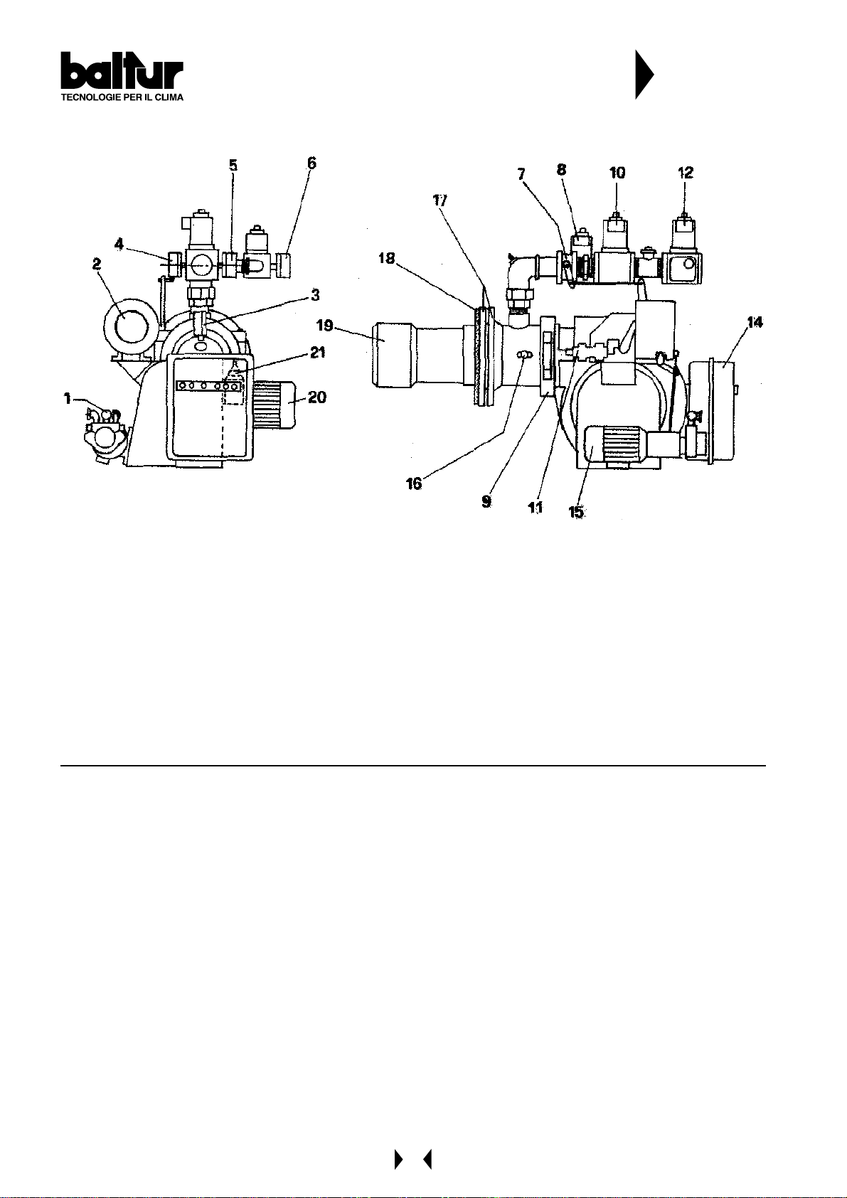
Elenco componenti
Component List
Lista de los componentes
N° 0002570030
Rev.
1 - Pompa
2 - Modulatore
3 - Pressostato aria
4 - Pressostato gas minima
5 - Pressostato gas massima
6 - Pressostato gas massima
7 - V alvola a farfalla
8 - Valvola funzionamento rampa pilot a
9 - Cerniera
10 - Valvola funzionamento
1 - Pump
2 - Modulator
3 - Aire pressure switch
4 - Gas pressure switch min.
5 - Gas pressure switch max.
6 - Gas pressure switch max.
7 - Butterfly
8 - Pilot main valve
9 - Hinge
10 - Main valve
1 1 - Regulation valve return pressure
12 - Safety valve
14 - Electric board
15 - Pump motore
16 - Combustion head air control knob
17 - Burner fixing flange
18 - Gasket
19 - Combustion head
20 - Fan motor
21 - Electromagnet
11 - Valvola regolatrice di pressione
12 - V alvola di sicurezza
14 - Quadro elettrico
15 - Motore pompa
16 - Vite regolazione aria alla testa di combustione
17 - Flangia attacco bruciatore
18 - Guarnizione isolante
19 - Testa di combustione
20 - Motore ventola
21 - Elettromagnete
1 - Bomba
2 - Modulator
3 - Presóstato aire
4 - Presóstato gas mínima
5 - Presóstato gas máxima
6 - Presóstato gas máxima
7 - Válvula de mariposa
6 - Válvula funcionamiento tren piloto
9 - Bisagra
10 - Válvula de funcionamiento
1 1 - Válvula de regulación presión
12 - Válvula de seguridad
14 - Cuadro eléctrico
15 - Motor bomba
16 - Tornillo regulaciónaire en el cabezal de combustión
17 - Brida unión quemador
18 - Empaquetadura aislante
19 - Cabezal de combustión
20 - Motor ventilador
21 - Electroimán
4
Page 5
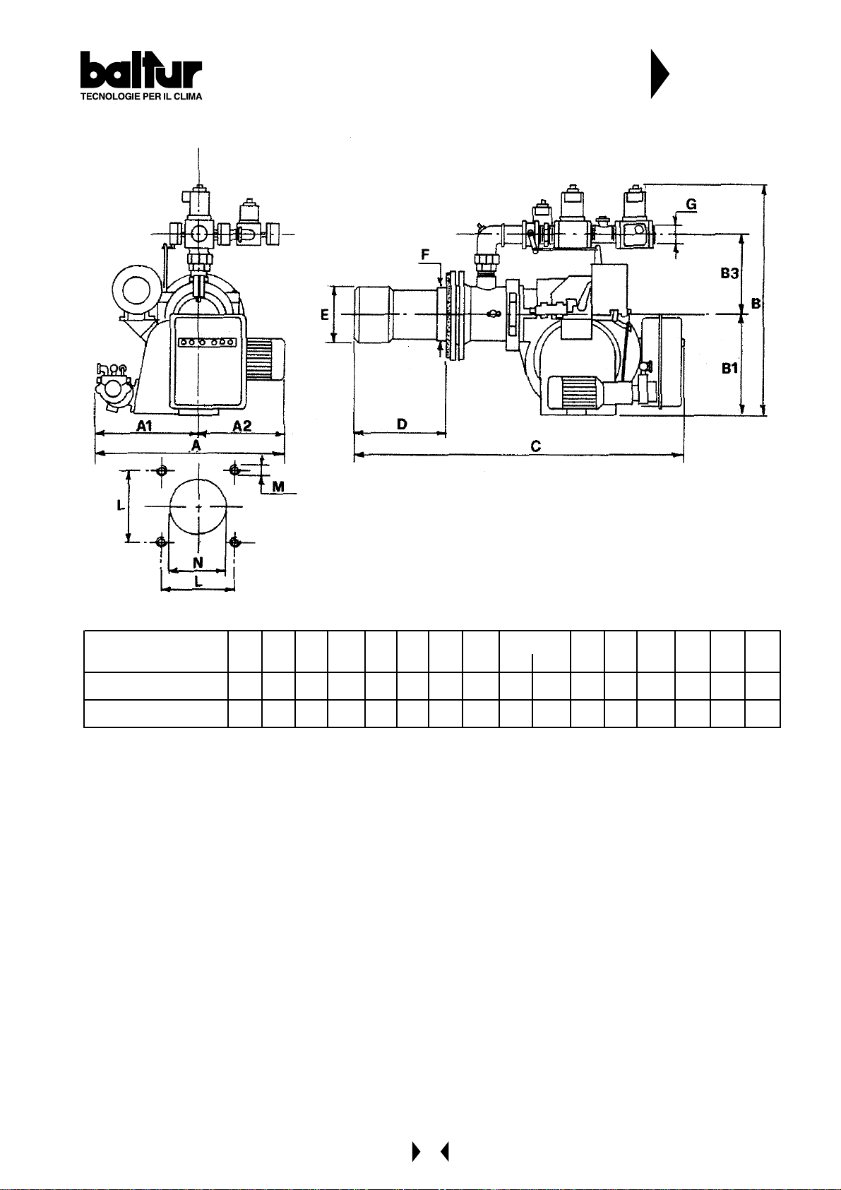
Dimensioni / Dimensions / Dimensiones
N° 0002570030
Rev.
MOD.
COM IST 7 2 DSPG M
COMI S T 122 DS P GM
A A1 A2 B B1 B2 B3 C D E F G L M N
MIN MAX Ø Ø Ø Ø
670 400 270 810 375 43 5 265 1410 185 445 227 220 2" 240 M16 240
830 460 370 1170 455 715 - 1500 195 455 227 220 2"1/2 240 M16 240
5
Page 6
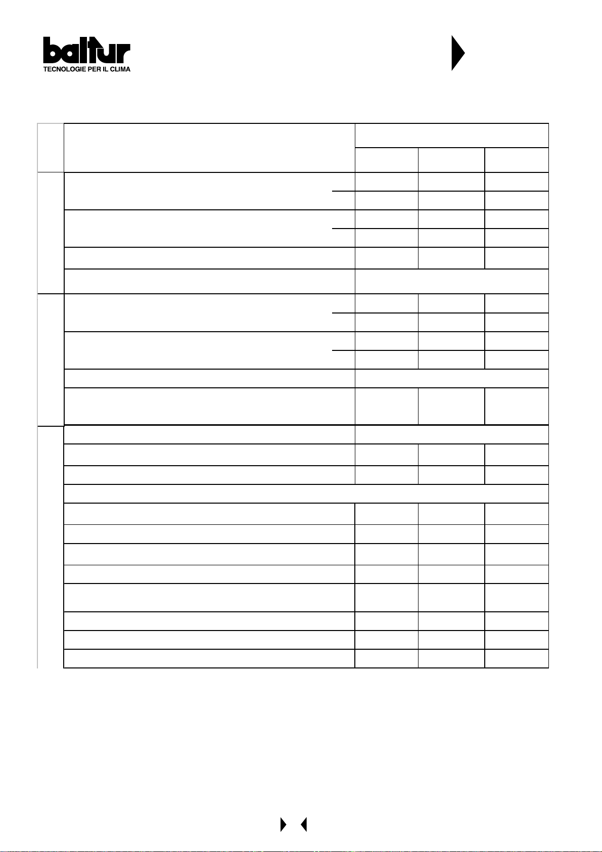
CARA TTERISTICHE TECNICHE
W
W
TECHNICAL DA T A
CARACTIRÍSTICAS TÉCNICAS
N° 0002570100
Rev.
CARATTERIS T ICHE TECNICHE / T ECHNICAL DAT A
CARACTERÍST ICAS T ÉCNICAS / T ECHNIS CHE DAT EN
POTENZA TERMICA / THERMIC CA PACITY /
POTENCIA TÉRMICA / HEIZLEISTUNG
PORTATA / FLOW RATE / CAUDAL / DURCHSATZ
PRESSIONE MIN.(*) / MIN. PRESSURE (*) /
METANO /
PRESIÓN METANO MÍN. (*) / DRUCK MIN. (*)
NATURAL GAS
TRASFORMATORE METANO / NAT. GAS TRANSFORMER /
TRANSFORMADORES DE ENCENDIDO METANO
POTENZA TERMICA / THERMIC CA PACITY /
POTENCIA TÉRMICA / HEIZLEISTUNG
PORTATA / FLOW RATE / CAUDAL / DURCHSATZ
VISC OSIT A ' COMBUSTIBILE / FU EL VISCO SITY / VISCOSIDAD COMBUSTIBLE
TRASFORMATORE GASOLIO / LI GHT OIL TRANSFORMER
GASÓLEO / HEIZÖL
GASOLIO /LIGHT OIL
TRANSFORMADORES DE ENCENDIDO GASÓLEO / ZÜNDTRAFO
MODELL O / M O DEL /
MODELO / MODELL
COMIST 180 COMIST 250 COMIST 300
DSPGM DSPGM DSPGM
MAk
MI k
MAX m³/h 199 340 390
MIN m³/h 69 113 131
CE
bar 37 150 150
1981 33 80 3878
688 1127 1304
8 kV - 20 mA
MAX kW 1981 3380 3878
MIN kW 688 1127 1304
MAX kg/h 167 285 327
MIN kg/h 58 95 110
1,5° E a/at 20° C
12 kV - 30 mA
14 kV - 30 mA 14 kV - 30 mA
TENSIONE / VOLTA GE / TENSIÓN / SPANNUNG
MOTORE VENTOLA / FAN MOTOR /
MOTORES VENTILA DOR / LÜFTERMOTOR
MOTORE POMPA / PUMP MOTOR / MOTORES BOMBA / PUMPM OTOR
Vol
kW/r.p.m.
kW/r.p.m.
230/ 400 - 50 Hz
3 - 2870 7, 5 - 2870 7,5 - 2870
0,75 - 28 00 1, 5 - 2800 1,5 - 2800
MAT ERI A L E A CO RREDO / S T ANDARD ACCESSO RIES / MATERI AL EN DOTACIÓN / STANDAR DZUBEHÖR
FLANGIA ATTACCO BRUCIAT. / BURNER FIXING FLANGE /
BRIDA UNIÓN / BEFESTIGUNGSFLANSCH
COLLARE ELASTICO / ELASTIC COLLAR / COLLARÍN ELÁSTICO / FEDER
GUARNIZIONE ISOLANTE / INSULATING GASKET /
EMPAQUETADURA / ISOLIERDICHTUNG
FILTRO / FILTE R
TUBI FLESSIBILI / FLEXIBLE PIPE / TUBOS FLEXIBLES / SCHLÄUCHE
PRIGIONIERI / STUD BOLTS / ESPÁRRAGOS / STIFTSCHRAUBEN
DADI / EXAGONAL NUTS / TUERCAS / SECHSKANTMUTTERN
RONDELLE PIA NE / FLA T WA SHERS / A RANDELA S / FLACHSCHEIBEN
111
- - 1 1
222
1"¼ 1"¼ 1"1/4
N°2
1"¼x1"¼
N°2
1"¼x1"¼
N°2
1"¼x1"¼
N°6 M20N°3 M20N°3 M20
N°6 M20N°3 M20N°3 M20
N°6 ø20N°3 ø20N°3 ø20
6
Page 7
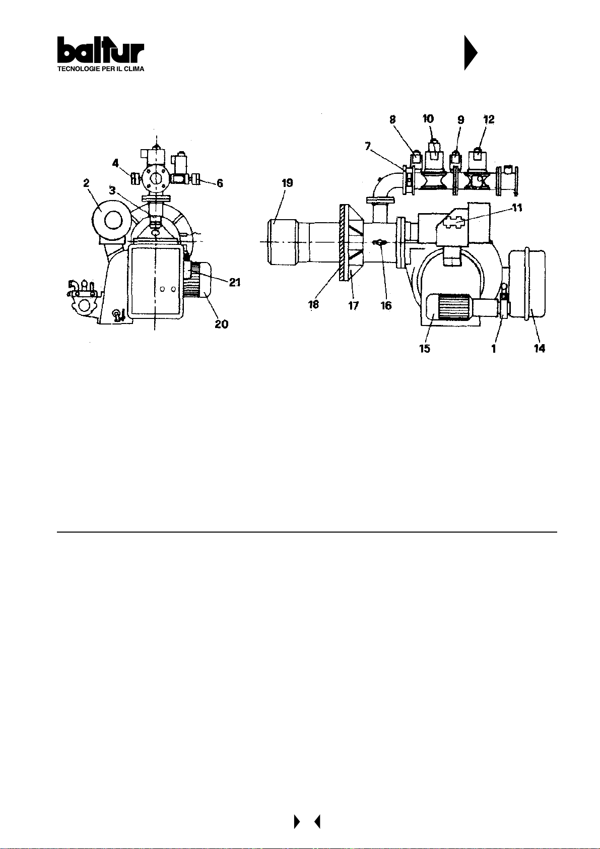
CARA TTERISTICHE TECNICHE
TECHNICAL DA T A
CARACTIRÍSTICAS TÉCNICAS
N° 0002570100
Rev.
1 - Pompa
2 - Modulatore
3 - Pressostato aria
4 - Pressostato gas minima
5 - Pressostato gas massima
6 - Pressostato gas massima
7 - Valvola a farfalla
8 - Valvola funzionamento rampa pilot a
9 - Valvola sicurezza rampa pilot a
10 - Valvola funzionamento
1 - Pump
2 - Modulator
3 - Aire pressure switch
4 - Gas pressure switch min.
5 - Gas pressure switch max.
6 - Gas pressure switch max.
7 - Butterfly
8 - Pilot main valve
9 - Pilot safety valve
10 - Main valve
1 1 - Regulation valve return pressure
12 - Safety valve
14 - Electric board
15 - Pump motore
16 - Combustion head air control knob
17 - Burner fixing flange
18 - Gasket
19 - Combustion head
20 - Fan motor
21 - Electromagnet
1 1 - V alvola regolatrice di pressione
12 - Valvola di sicurezza
14 - Quadro elettrico
15 - Motore pompa
16 - Vite regolazione aria alla testa di combustione
17 - Flangia attacco bruciatore
18 - Guarnizione isolante
19 - Testa di combustione
20 - Motore ventola
21 - Elettromagnete
1 - Bomba
2 - Modulator
3 - Presóstato aire
4 - Presóstato gas mínima
5 - Presóstato gas máxima
6 - Presóstato gas máxima
7 - Válvula de mariposa
6 - Válvula funcionamiento tren piloto
9 - Válvula de seguridad tren piloto
10 - Válvula de funcionamiento
1 1 - Válvula de regulación presión
12 - Válvula de seguridad
14 - Cuadro eléctrico
15 - Motor bomba
16 - T ornillo regulaciónaire en el cabezal de combustión
17 - Brida unión quemador
18 - Empaquetadura aislante
19 - Cabezal de combustión
20 - Motor ventilador
21 - Electroimán
7
Page 8
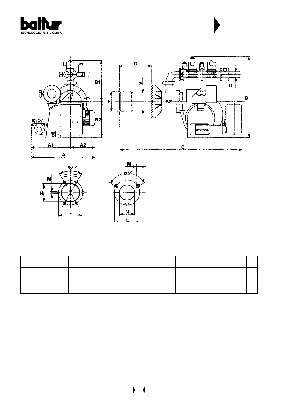
Dimensioni / Dimensions / Dimensiones
M
M
M
N° 0002570100
Rev.
Mod.
COMIST 1 80 DSP G
COMIST 2 50 DSP G
COMIST 3 00 DSP G
AA1A2BB1B2CDEFGLMN
min max min max
875 460 415 1225 510 715 1725 330 520 260 245 2”1/ 2G 400 400 M 20 300
1075 540 535 1300 580 720 1750 320 500 320 273 3”G 490 490 M 20 340
1075 540 535 1300 580 720 1750 320 500 320 273 3”G 490 490 M 20 350
8
Page 9
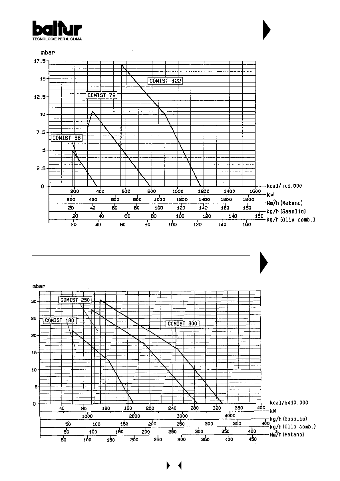
COMIST 36 - 72 - 122
N° 8187/1
Rev.
COMIST 180 - 250 - 300
N° 8111/2
Rev.
9
Page 10
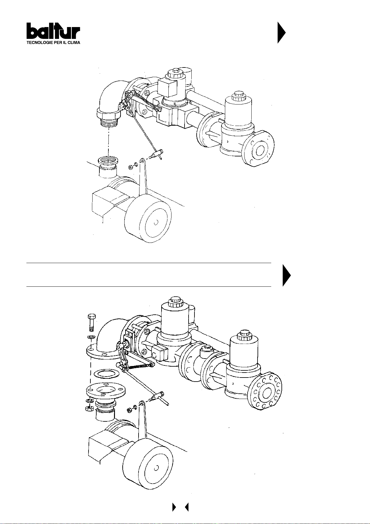
DRAWING SHOWING THE GAS TRAIN ASSEMBL Y
COMIST 72 MG - DSPGM
N° 8805
Rev.
DRAWING SHOWING THE GAS TRAIN ASSEMBL Y
COMIST 122 - 180 - 250 - 300 MG - DSPGM - DSPNM
N° 8797
Rev.
10
Page 11
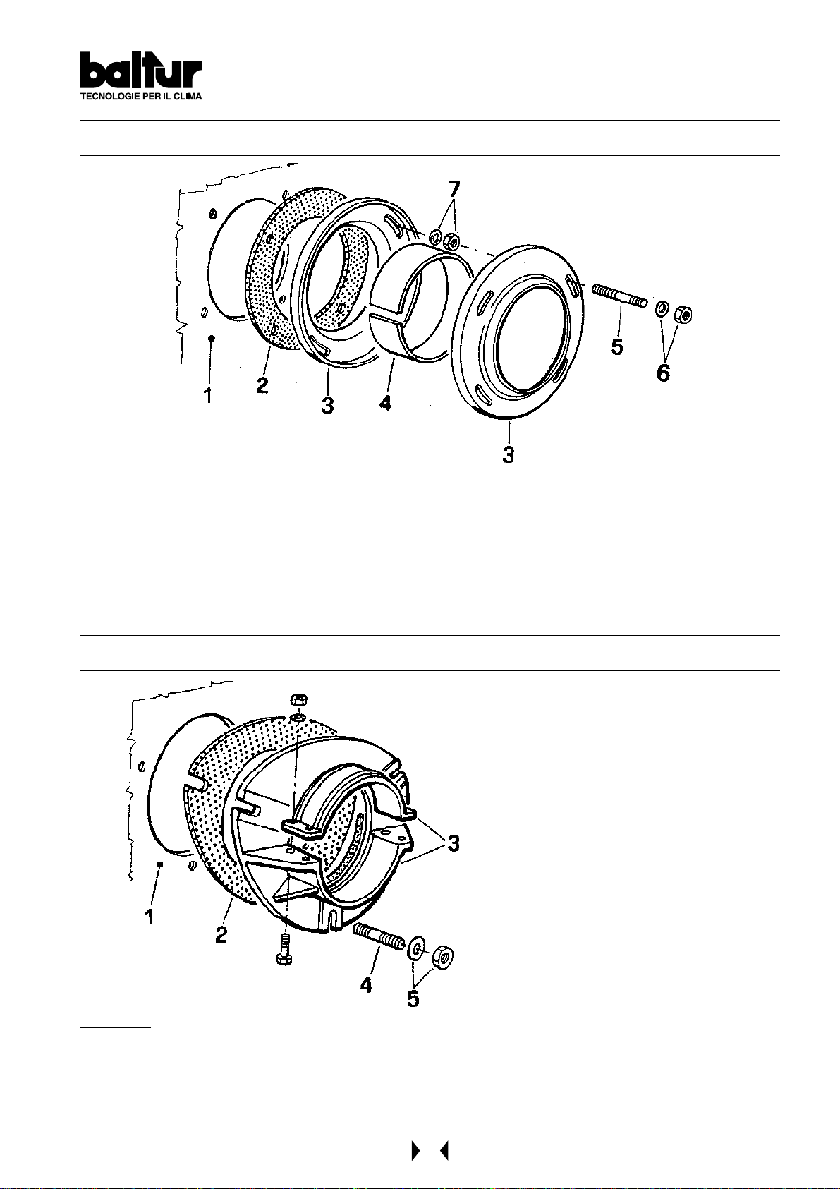
APPLICATION OF THE BURNER TO BOILER
for model COMIST 72 - 122 DSPGM (steel fixing flange)
1 - Boiler plate
2 - Insulating gasket
3 - Burner fixing flange
4 - Elastic collar
for model COMIST 250 - 300 DSPGM
5 - Stud bolt
6 - Locking nut with washer
7 - Nut and washer for fastening the first flange
1 - Boiler plate
2 - Insulating gasket
3 - Burner fixing flange
4 - Stud bolt
5 - Locking nut with washer
REMARKS
When tightening the flange, it is important to do it evenly so that the inner faces are parallel between them.
Since the locking system is highly efficient, do not tighten the nuts too much.
During this operation (tightening of the flange locking nuts) keep the body of the burner lifted so that the
combustion head is kept in a horizontal position.
11
Page 12
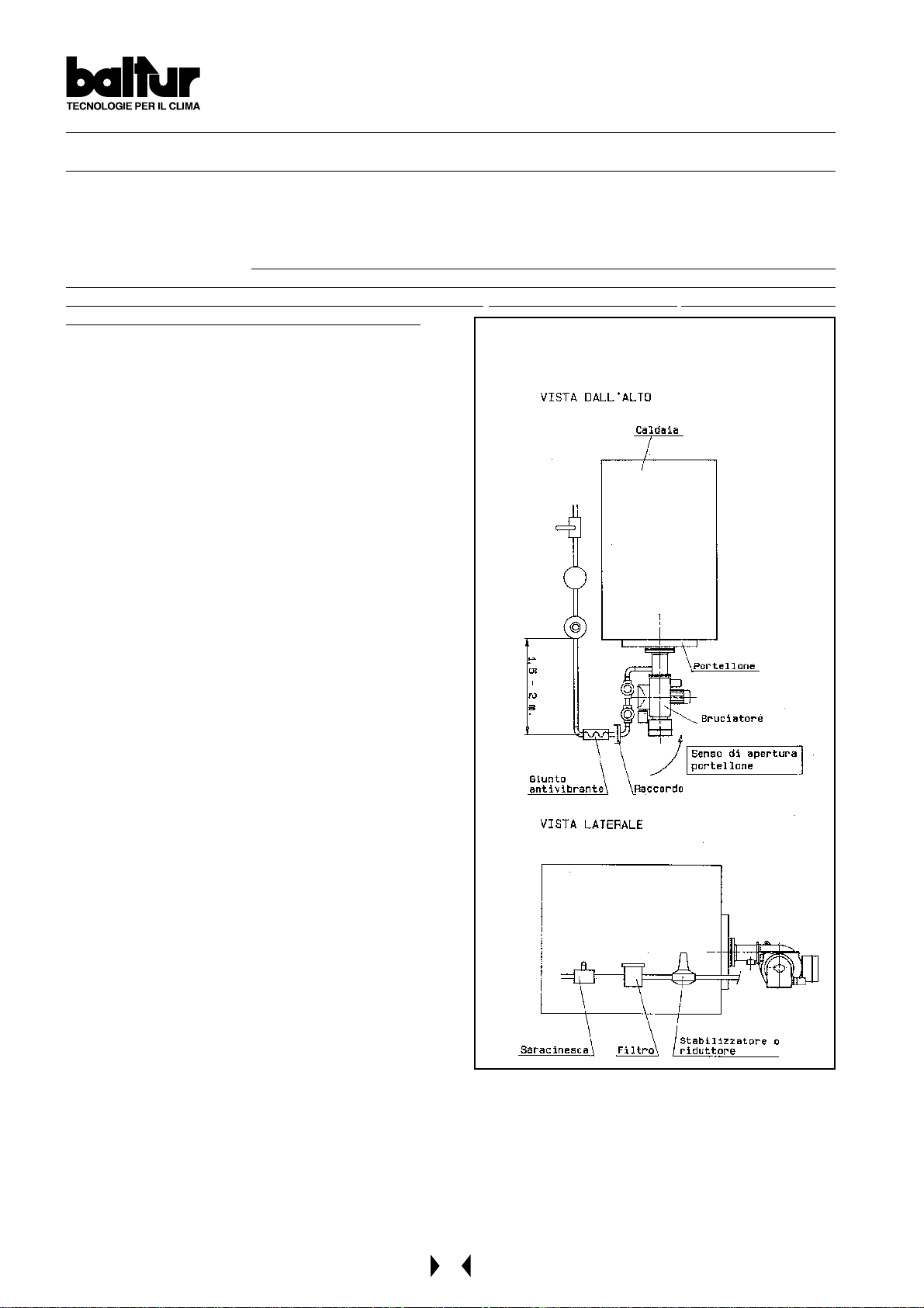
GAS FEED SYSTEM AT LOW PRESSURE ( max. 400 mm.C.A )
When the burner has been correctly fastened to the boiler, proceed with connecting it to the gas pipeline
(see BT 8780 and BT 1387). The dimension of the gas adduction pipeline should be in proportion to its length and
to gas delivery and the load loss should not exceed 5 mm W. C. (see diagram). It must also be perfectly hermetic
and adequately tested before the burner’s general inspection. It is indispensable to install a proper fitting on the
pipeline, in proximity to the burner, to allow for easy disassembling of the burner and/or opening of the boiler door .
In addition, the following should be installed: a cut -off cock, a gas filter , a st abilizer or a pressure regulator (when
the feed pressure is superior to 400 mm W. C. = 0,04 Kg/cm2), and an antivibration joint. These parts should be
installed as described in our drawing (see BT 8780).
We consider it useful to give the following practical tips for
installing the essential accessories on the gas pipeline near
to the burner:
1) To avoid big drops in pressure on ignition, the length of
the pipeline between the point where the stabilizer or
reducer is fitted and the burner should be from 1,5 to 2
m. This pipe must have a diameter equal or superior to
that of the burner attachment fitting.
2) The fitting must be applied on horizontal pipes.
This is to avoid any impurities falling into the pipes or
entering the stabilizer during cleaning.
3) T o get the best performance out of the pressure st abilizer,
it is advisable to fit it onto horizontal pipes, after the filter .
In this way, the vertical movement of the entire mobile
part (shutter) of the stabilizer is rapid. (If the movement
of the mobile part were horizontal - with the stabilizer
fitted into vertical pipes - friction to the guide bush/es of
the pin to which the entire mobile part is fitted would
delay movement).
GENERAL DIAGRAM FOR INSTALLATION OF
GATE-FILTER-STABILIZER-ANTIVIBRA TION JOINT
OPENABLE PITTING
N° BT 8780
4) We advise installing a bend directly onto the burner gas
ramp before applying the removable fitting. This layout
makes it possible to open the boiler door, if there is one,
after the pipe fitting itself has been opened. The above
information is clearly illustrated in drawing BT 8780.
12
Page 13
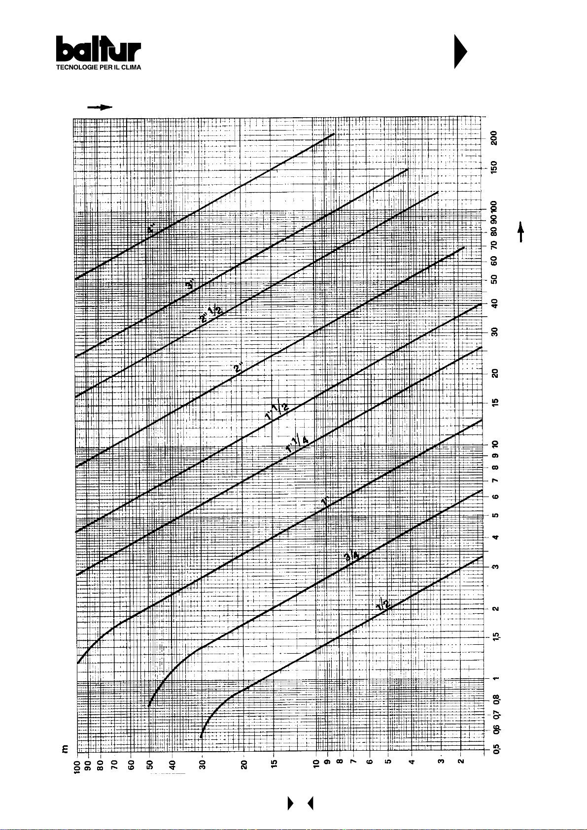
FLOW (m3/h) METHANE GAS (d=0,85) IN
COMMERCIAL GAS PIPES (UNI 3824-68)
LOAD LOSS MAX. 5 mm W . C.
VIRTUAL LENGTH IN METERS
N° BT 1387
/h
3
FLOW m
13
Page 14
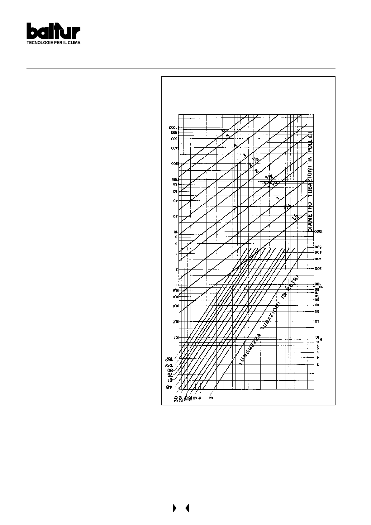
GAS FEED SYSTEM AT AVERAGE PRESSURE a few bars (see BT 8058-BT 8530/1-8531/1)
When high delivery is required, the Gas
Distributing Company requests the installation of
a unit comprising a pressure reducer and a meter,
and then connects it to the gas pipe network at
average pressure (a few bars).
This unit can be supplied by the Gas Distributing
Company or by the user , but should be according
to the Gas Company’s precise instructions.
The unit’s pressure reducer should be large
enough to supply the maximum gas delivery
required by the burner at the rate of pressure
normally estimated for it.
From experience, we would recommend utilising
a large-scale reducer in order to attenuate the
notable increase in pressure which occurs when
the burner comes to a standstill, with a high
delivery . (Regulations require that the gas valves
close in less than one second).
As an indication, we would advise using a reducer
capable of producing at delivery (m3/h) about
double that of the maximum amount estimated
for the burner.
If several burners are to be used, each one should
have its own pressure reducer; this will enable
the gas feed pressure to the burner to be
maintained at a constant level even if only one
burner is operating at the time.
Consequently , it is possible to accurately regulate
the delivery and therefore the combustion, and
thus improve yield.
The dimension of the gas pipeline should be in
function with the quantity of gas it has to deliver.
We advise maintaining the load loss at a low level
(not more than 10% of the gas pressure value at
the burner); it should be kept in mind that the
load loss is added to the pressure existing when
the burner stops and therefore a subsequent start
up will occur at a pressure that rises in
accordance with an increase in the pipe’s load
loss. Should the gas pressure reach
unacceptable values when the burner stops
(rapid closure of the gas valves), it is necessary
to install between the reducer and the first valve
of the burner an automatic overflow valve and
relative conveying pipe, of suitable section, in the
open air.
The end of conveying pipe in the open air should terminate in a suitable place, be protected from rain and have a
flame trap. The overflow valve should be regulated in such a way as to completely unload excessive pressure.
See diagram BT 8058 for gas pipeline dimensions.
Near to the burner should also be fitted a cut-off ball cock, a gas filter , an anti-vibration joint and a flanged fitting
(see BT 8530/1 and BT 8531/1).
DIAGRAM FOR CALCULATING THE DIAMETER OF THE
PIPES IN RELATION TO THEIR LENGTH AND GAS FLOW
/h OF METHANE p.a. 0,60
c
FLOW IN m
LENGTH OF PIPES IN METERS
DIAMETER OF PIPES IN INCHES
O
2
PRESSURE DROP IN mm OF H
N° BT 8058
14
Page 15
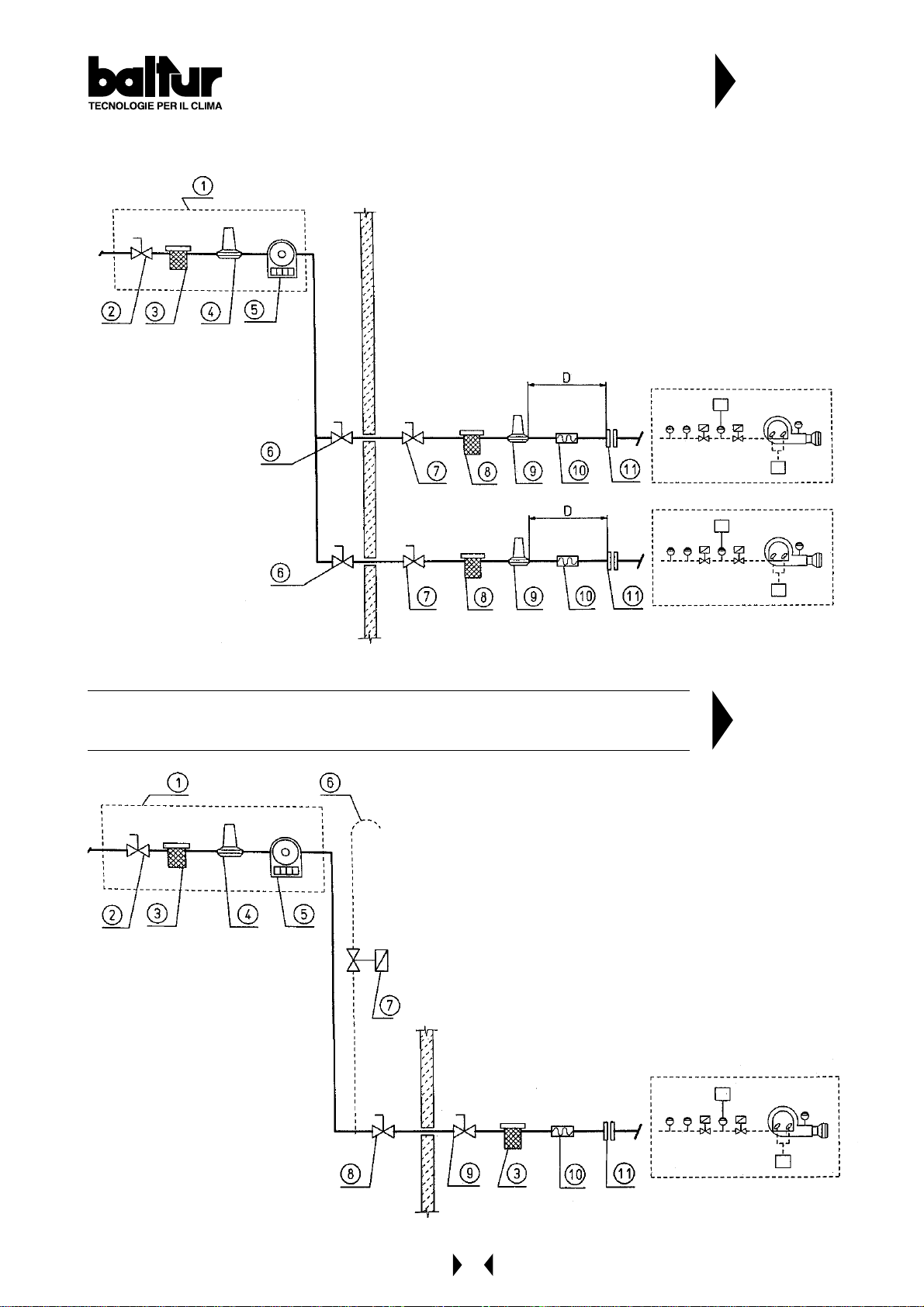
DIAGRAM OF CONNECTING MORE THAN ONE
BURNER TO THE GAS PIPE NETWORK
A T A VERAGE PRESSURE
1 - Measuring and reducing unit
2 - Interception
3 - Filter
4 - Reducer
5 - Meter
6 - Emergency interception (installed outside)
7 - Ball cock
8 - Filter
9 - Final reducer or stabilizer
10- Anti-vibration joint
11- A couple of flane
D = Distance between pressure stabilizer and valve about 1,5 ÷ 2 m
N° BT 8530/1
DIAGRAM OF CONNECTING A BURNER TO THE GAS PIPE NETWORK AT
A VERAGE PRESSURE
1 - Measuring and reducing unit
2 - Interception
3 - Filter
4 - Reducer
5 - Meter
6 - Wire gauze flame trap
7 - Eventual automatic overflow valve (it should obviously
unload outside in a suitable place)
8 - Emergency interception installed outside
9 - Ball cock
10- Anti-vibration joint
11- A couple of flange
N° BT 8531/1
15
Page 16

ELECTRICAL CONNECTIONS
It is advisable to make all connections with flexible electric wire.
The electric lines should be at an adequate distance from hot parts.
Make sure that the electric line to which the unit will be connected has frequency and voltage ratings suitable for
the burner.
Check that the main line, the relevant switch with fuses (essential) and the current limiter (if required) are capable
of withstanding the maximum current absorber by the burner .
For details, refer to the specific electric diagram for each single burner .
FUEL FEED SYSTEM
The burner pump should receive fuel from a feed circuit which has an ancillary pump and, in some cases, a
pressure regulator capable of modifying the pressure value 0,2 to 1 bar (see drawing BT 0002901120).
In this case, the value of the fuel feed pressure at the burner pump (0,2 ÷ 1 bar) should not vary when the burner
is at a standstill or when it is operating at the maximum fuel delivery required by the boiler.
Normally it is possible to realize a circuit without a pressure regulator as shown in drawing n° BT 8666/3.
The feed circuit must be realized according to drawing 0002901 120 or to drawing BT 8666/3.
The dimension of the pipelines should be in function with their length and with the output of the pump utilized.
Our instructions cover the basic requirements needed to ensure efficient operations.
All rules and regulations existing in the country of installation should be strictly complied with and the local fire
brigade should be consulted.
FURTHER INSTRUCTIONS TO START A MIXED BURNER
It is advisable to first carry out the starting with the liquid fuel because in this case the delivery is conditioned by the
available nozzle whereas the delivery of methane be varied as you like by working on its delivery regulator .
16
Page 17
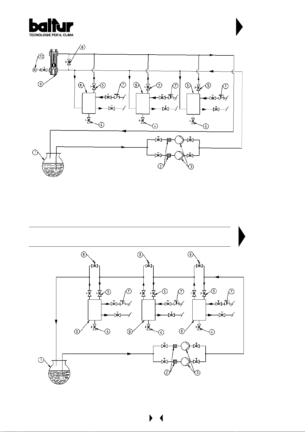
FUEL FEEDING HYDRAULIC DIAGRAM FOR ONE
OR MORE LIGHT OIL BURNERS
WITH MAXIMUM NOMINAL VISCOSITY (5 °E at 50 °C)
1 Main cictern
2 Filter
3 Circulation pump
4 Water and system drain
6 Fuel recovery and degasifier
7 One-way valve
8 By-pass (usually closed)
9 Feeding circuit presure regulator adjustment range between 0.2 and 1 bar
10 Pressure gauge (0 - 4 bar)
The combustible recovery and degasifier
tanks (diameter ~ 150, height ~ 400)
should be installed as near as possible
to the burner and should be about 0,5 m.
higher with respect to the burner's pump.
N° 0002901 120
rev.:19/02/2002
DIAGRAM OF PIPES OF FEED SYSTEM FOR LIGHT OIL BURNERS
WITH MAXIMUM NOMINAL VISCOSITY (5 °E at 50 °C)
1 Main cictern
2 Filter
3 Circulation pumps
4 Water and system drain
5 Air-gas drain usually closed
6 Fuel recovery and degasifier
7 One-way valve
8 By-pass (usually closed)
The combustible recovery and degasifier tanks (diameter
~ 150, height ~ 400) should be installed as near as
possible to the burner and should be about 0,5 m. higher
with respect to the burner's pump.
N° BT 8666/3
17
Page 18
DESCRIPTION OF TWO ST AGE PROGRESSIVE OPERATIONS WITH LIGHT OIL
COMIST...DSPGM (See BT 8714/2)
This is referred to as a 2-stage progressive operation because the passage from the 1st flame to the 2nd flame
(from the minimum rate to the maximum pre-established rate) takes place gradually both as delivery of combustion
air and of fuel. The burner’s control box (cyclic relay) is connected by operating panel switch ( I ).
Control box specifications
Control box
& relative
Programmer
LFL 1.333
Cyclic relay
The cyclic relay control box carries out the ignition programme by starting up the fan motor and thus the pump in
order to effect the pre-ventilation and light oil pre-circulation phases.
It is necessary that the air pressure supplied by the fan is sufficient to cause the intervention of the relative
pressure switch, if not, the control box will go to “shut down”.
Oil from the pump reaches the atomizer unit and circulates within it because the passages leading to the outward
and return nozzles are closed. This closure is carried out by “closing pins” applied to the ends of the rods.
These “pins” are pressed against their seats by strong springs which are situated at the opposite ends of the rods.
The oil circulates, comes out of the atomizer unit return and arrives at the return pressure regulator.
It passes through this and reaches the pump return and from there it is discharged back into the return.
Oil circulation, as described above, should be carried out at a pressure value slightly higher (by some bar) than the
minimum pressure at which the return pressure regulator has been set (10 ÷ 12 bar).
Duration of the pre-ventilation and oil pre-circulation phase is not as foreseen by the control box, because it is
effected when the air shutter is in an open position.
The pre-ventilation and pre-circulation time is calculated by summing together the times of the following manoeuvres:
- the delivery regulation servomotor’s opening stroke (fuel/air) +
- preventilation time foreseen by the control box +
- the closing stroke of the delivery regulation servomotor (fuel/air) until ignition air position.
Subsequently , the control box continues carrying out the ignition programme by connecting the ignition transformer
which feeds the electrodes with high voltage. The voltage between the electrodes primes the electric spark for
ignition of the fuel/air mixture. After the insertion spark appears, the control box carries voltage to the magnet
which, by means of appropriate levers, moves backwards the two rods which intercept the flow (outward and
return) of light oil to the nozzle. This moving backwards of the rods also determines a closing of the passage (bypass) inside the atomizer unit. Consequently , the pump pressure is taken to the normal value of about 20 ÷ 22 bar .
Deviation of the two rods the closing seat, now permits the fuel to enter the nozzle at the pressure at which the
pump has been regulated at (20 ÷ 22 bar), and comes out of the nozzle adequately atomized.
The return pressure, which determines delivery to the furnace, is regulated by the return pressure regulator.
The value of the ignition flow rate (minimum delivery) should be about 10 ÷ 12 bar.
The atomized light oil which comes out of the nozzle is mixed with air supplied by the fan and is then ignited by the
spark of the electrodes. Flame presence is detected by the photocell UV.
The programme proceeds and surpasses the “shut down” position, disconnects the ignition transformer and by
this point on the burner is operating at minimum output.
If the boiler thermostat (or pressure switch) of the 2nd stage allows it (regulated at a temperature or pressure value
superior to that existing in the boiler), the servomotor which regulates the delivery starts turning and determines a
gradual increase in the fuel delivery and in the relative combustion air until it reaches the maximum delivery value
at which the burner has been regulated. The increase in fuel delivery is determined by a disk with a varied profile
which, by rotating, can determine a greater compression of the return pressure regulator spring and thus an
increase in the pressure itself. When the return pressure increases, there is also a corresponding increase in fuel
delivery . There should also be an adequate increase in combustion air to meet the increase in fuel delivery.
Adjustment can be carried out at first regulation by operating the screws which vary the profile of the commend
disk of the combustion air regulator.
Safety
time in
seconds
3
Pre-Ventilation &
Oil Pre-circulation
Time
in seconds
31,5
Pre-ignition
Time
in seconds
6
Post-ignition
Time
in seconds
3
Time between
1st flame & Start
of Modulation
in seconds
12
18
Page 19

Fuel and combustion air delivery both increase at the same time until they reach maximum value (light oil pressure
at the return pressure regulator is equal to about 18 ÷ 20 bar if the pressure at the pump is at the value of 20 ÷ 22
bar). The burner remains in the maximum delivery position until the temperature or pressure reaches the limit set
for the intervention of the boiler thermostat (or pressure switch) of the 2nd stage and makes the servomotor
regulating fuel/air delivery rotate in the opposite sense of direction, a causing gradual reduction in fuel delivery and
a relative reduction in combustion air until they reach minimum value.
Should the maximum temperature (pressure, if steam boiler), be reached even with fuel and combustion air
delivery at a minimum, the thermostat (pressure switch, if steam boiler) will intervene when the value at which it
has been set is reached, and bring the burner to a standstill. When the temperature (pressure, if steam boiler)
drops below the intervention limit of the “shut down” device, the burner will start up again as previously described.
During normal operations, the boiler thermostat / pressure switch of the 2nd stage fitted to the boiler detects the
variations requested and automatically proceeds with adapting the fuel and combustion air delivery by inserting
the servomotor which regulates delivery (fuel/air). This will rotate in such a way as to obtain an increase or a
decrease. In this way , the delivery regulating system (fuel/air) reaches a position of equilibrium which corresponds
to a fuel delivery and a relative combustion air delivery equal to the quantity of heat required by the boiler.
As in indication, it should be kept in mind that the field of variation in output obtainable with good combustion is
from 1 to 1/3 of the maximum output given on the rating plate.
Note: The air pressure switch must be set when the burner is started up and must be in function with the pressure
value verified during operations with the ignition flame; otherwise the control box will go to “shut down”.
DESCRIPTION OF MODULATING OPERATIONS WITH LIGHT OIL (COMIST...MM) (See BT 8714/2)
The burner’s control box (cyclic relay) is connected by operating panel switch ( I ).
Control box specifications
Control box
& relative
Programmer
LFL 1.333
Safety Time
in seconds
3
Pre-Ventilation &
Oil Pre-circulation
Time
in seconds
31,5
Pre-ignition
Time
in seconds
6
Post-ignition
Time
in seconds
3
Time between
1st flame & Start
of Modulation
in seconds
12
Cyclic relay
The cyclic relay control box carries out the ignition programme by starting up the fan motor and thus the pump in
order to effect the pre-ventilation and light oil pre-circulation phases.
It is necessary that the air pressure supplied by the fan is sufficient to cause the intervention of the relative
pressure switch, if not, the control box will go to “shut down”.
Oil from the pump reaches the atomizer unit and circulates within it because the passages leading to the outward
and return nozzles are closed.
This closure is carried out by “closing pins” applied to the ends of the rods.
These “pins” are pressed against their seats by strong springs which are situated at the opposite ends of the rods.
The oil circulates, comes out of the atomizer unit return and arrives at the return pressure regulator.
It passes through this and reaches the pump return and from there it is discharged back into the return.
Oil circulation, as described above, should be carried out at a pressure value slightly higher (by some bar) than the
minimum pressure at which the return pressure regulator has been set (10 ÷ 12 bar).
Duration of the pre-ventilation and oil pre-circulation phase is not as foreseen by the control box, because it is
effected when the air shutter is in an open position.
The pre-ventilation and pre-circulation time is calculated by summing together the times of the following manoeuvres:
- the delivery regulation servomotor’s opening stroke (fuel/air) +
- pre-ventilation time foreseen by the control box +
- the closing stroke of the delivery regulation servomotor (fuel/air) until ignition air
position .
Subsequently , the control box continues carrying out the ignition programme by connecting the ignition transformer
which feeds the electrodes with high voltage.
The voltage between the electrodes primes the electric spark for ignition of the fuel/air mixture.
19
Page 20

After the insertion spark appears, the control box carries voltage to the magnet which, by means of appropriate
levers, moves backwards the two rods which intercept the flow (outward and return) of light oil to the nozzle.
This moving backwards of the rods also determines a closing of the passage (by-pass) inside the atomizer unit.
Consequently , the pump pressure is t aken to the normal value of about 20 ÷ 22 bar.
Deviation of the two rods from the closing seat, now permits the fuel to enter the nozzle at the pressure at which
the pump has been regulated at (20 ÷ 22 bar), and comes out of the nozzle adequately atomized.
The return pressure, which determines delivery to the furnace, is regulated by the return pressure regulator.
The value of the ignition flow rate (minimum delivery) should be about 10 ÷ 12 bar.
The atomized light oil which comes out of the nozzle is mixed with air supplied by the fan and is then ignited by the
spark of the electrodes. Flame presence is detected by the photocell UV.
The programme proceeds and surpasses the “shut down” position, disconnects the ignition transformer , and then
connects the modulation circuit. The modulation motor commands an increase in the delivery of fuel and combustion
air at the same time. The increase in fuel delivery is determined by a disk with a varied profile which, by rotating,
can determine a greater compression of the return pressure regulator spring and thus an increase in the pressure
itself. When the return pressure increases, there is also a corresponding increase in fuel delivery.
There should also be an adequate increase in combustion air to meet the increase in fuel delivery .
Adjustment can be carried out at first regulation by operating the screws which vary the profile of the commend
disk of the combustion air regulator. Fuel and combustion air delivery both increase at the same time until they
reach maximum value (light oil pressure at the return pressure regulator is equal to about 18 ÷ 20 bar if the
pressure at the pump is at the value of 20 ÷ 22 bar). Fuel and combustion air delivery remain at maximum value
until the boiler temperature (pressure, if steam boiler), approaches the value at which it has been set and causes
the servomotor regulating fuel/air delivery to reverse its previous sense of movement. The return movement of the
modulation causes a reduction in light oil delivery and a relative reduction in combustion air.
The modulation system reaches a position of equilibrium which corresponds to a fuel delivery and a relative
combustion air delivery equal to the quantity of heat required by the boiler. With the boiler operating, the probe in
the boiler is aware of load variation in the boiler and automatically commands the modulation motor to make an
adjustment in the light oil delivery and in the relative combustion air.
Should the maximum temperature (pressure, if steam boiler), be reached even with fuel and combustion air
delivery at a minimum, the thermostat (pressure switch, if steam boiler) will intervene when the value at which it
has been set is reached, and bring the burner to a standstill. When the temperature (pressure, if steam boiler)
drops below the intervention limit of the “shut down” device, the burner will start up again as previously described.
The air pressure switch must be regulated at the burner ignition, in relation to the pressure value obtained whit
ignition flame; on the contrary the control box stops in lock position.
Note: As an indication, it should be kept in mind that the field of variation in output obtainable with a good quality
fuel is from 1 to 1/3 of the maximum output given on the rating plate.
20
Page 21
CONNECTION AT THE
FUEL FEEDING
DIAGRAM FOR ONE
OR MORE BURNERS
(SEE 0002901120)
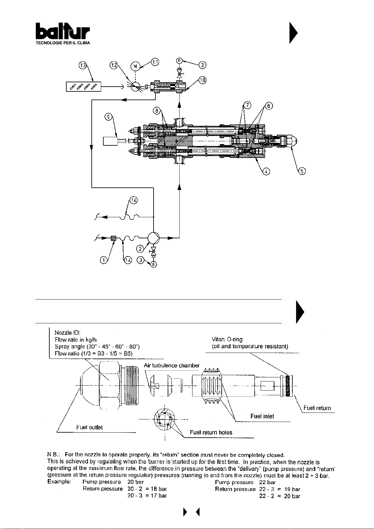
DIAGRAM OF LIGHT OIL MODULATING
BURNERS ( MAGNET - NOZZLE WITHOUT PIN)
1 FILTER
2 BURNER PUMP
3 PRESSURE GAUGE 0 - 40 BAR
4 ATOMIZER UNIT
5 RETURN NOZZLE WITHOUT PIN
6 ROD WITH CLOSING PINS
7 BY-PASS HOLES
8 CLOUSING SPRING
9 OPENING ELECTROMAGNET
10 RETURN PRESSURE REGULATOR
11 MODULATION SERVOMOTOR
12 CONTROL DISK FOR VARIATION OF FUEL / AIR DELIERY
13 AIR REGULATION SHUTTERS
14 FLEXIBLE PIPE
N° BT 8714/2
REV .: 19/02/2002
MIN = 10-12 BAR
MAX = 18-20 BAR
DIAGRAM OF A DISMANTLED ( C.B. ) CHARLES BERGONZO NOZZLE
(WITHOUT PIN)
N° BT 9353/1
21
Page 22
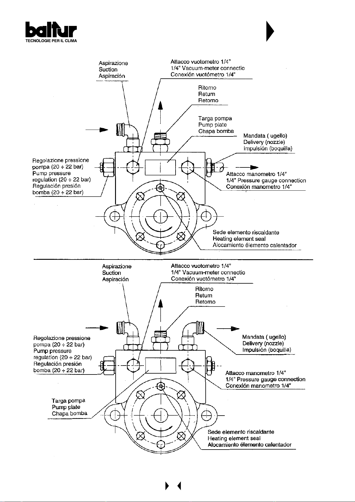
BAL TUR PUMP
N° 0002900580
22
Page 23

DESCRIPTION OF TWO ST AGE PROGRESSIVE OPERATION WITH NA TURAL GAS FOR
COMIST.....DSPGM (see N° 0002910610 and N° 0002910640)
CONTROL BOX SPECIFICATIONS
Control
box &
relative
programmer
LFL 1.333
Safety time in
seconds
3
Pre-ventilation
time with shutter
open
in seconds
31,5
Pre-ignition
in seconds
6
Post-ignition
in seconds
3
Time between
1st flame &
modulation start
in second
12
Cyclic relay
This is referred to as a 2-stage progressive operation because the passage from the 1st flame to the 2nd flame
(from the minimum rate to the maximum pre-established rate) takes place gradually.
The amount of combustion air and fuel delivery are increased very gradually and this ensure stabilization of the
gas feed network pressure.
The field of variation in flow obtainable is from 1 to 1/3.
The burner is fitted with an end-of-the-run switch (a micro-switch) which stops the burner starting up if the flow
regulator is not in the minimum position.
Before ignition, a pre-ventilation of the combustion chamber occurs (according to Regulations) with air open.
At the end of the ventilation phase, if the air ventilation pressure switch has measured sufficient pressure, the
ignition transformer will be connected and subsequently the ignition (pilot) valves and the safety valve will open.
Gas reaches the combustion head, mixes with air supplied by the fan, and is ignited.
Delivery is regulated by the flow regulator incorporated in the ignition flame (pilot) valve.
The ignition transformer is disconnected 3 seconds after the ignition flame and safety valves are inserted.
The burner is now operating with the ignition flame (pilot) only.
Flame presence is detected by a relative control device (ionization probe immersed in the flame, or UV cell).
The relay programmer passes the “shut down” position and gives voltage to the servomotor which regulates the
delivery (gas/air); the burner is now operating at minimum output.
If the boiler thermostat (or pressure switch) of the 2nd stage allows it (regulated at a temperature or pressure value
superior to that existing in the boiler), the servomotor which regulates the gas/air delivery starts turning and
determines a gradual increase in the gas delivery and in the relative combustion air until it reaches the maximum
delivery value at which the burner has been regulated.
N.B. The “V” cam of the servomotor regulating air/gas delivery (see BT 8562/1) inserts almost immediately the
principle gas valve, which in turn opens completely. Gas delivery is not determined by the principle valve
but by the position of the gas delivery regulation valve (see BT 8816/1 and BT 8813/1).
The burner remains in the maximum delivery position until the temperature or pressure reaches the limit set for the
intervention of the boiler thermostat (or pressure switch) of the 2nd stage and makes the servomotor regulating
gas/air delivery rotate in the opposite sense of direction.
Thus gas delivery and the relative combustion air are gradually reduced until they reach minimum value.
Even with delivery at a minimum, if the limit (temperature or pressure) at which the shut down device (thermostat
or pressure switch) has been regulated is reached, the burner will be brought to a standstill.
When the temperature or pressure drops below the intervention limit set on the shut down device, the burner will
start up again, according to the programme previously described.
During normal operations, the boiler thermostat/pressure switch of the 2nd stage fitted to the boiler detects the
variations requested and automatically proceeds with adapting the fuel and combustion air delivery by inserting
the servomotor which regulates delivery (gas-air). This will rotate in such a way as to obtain an increase or a
decrease. With this manoeuvre, the gas/air delivery regulating system try to equilibrate the quantity of heat supplied
to the boiler with that which the boiler gives to be utilized.
If the flame does not appear the control box goes to “shut down” (the burner stops completely and the relative
indicator light is turned on).
To unblock the control box, press the appropriate pushbutton.
23
Page 24

DESCRIPTION OF MODULATING OPERATIONS WITH NATURAL GAS FOR COMIST....MM
(see N° 0002910610 and N° 0002910640)
CONTROL BOX SPECIFICATIONS
Control box
&
relative
programmer
LFL 1:333
Safety time
in seconds
3
Pre-ventilation
time with
shutter open
in seconds
31,5
Pre-ignition
in seconds
6
Post-ignition
in seconds
3
Time between
1st flame &
modulation start
in seconds
12
Cyclic relay
The field of variation in flow obtainable is from 1 to 1/3.
The burner is fitted with an end-of-the-run switch (a micro-switch) which stops the burner starting up if the flow
regulator is not in the minimum position. Before ignition, a pre-ventilation of the combustion chamber occurs (according
to Regulations) with air open. At the end of the ventilation phase, if the air ventilation pressure switch has measured
sufficient pressure, the ignition transformer will be connected and subsequently the ignition flame (pilot) valves and
the safety valves will open. Gas reaches the combustion head, mixes with air supplied by the fan, and is ignited.
Delivery is regulated by the flow regulator incorporated in the ignition flame (pilot) valve.
The ignition transformer is disconnected after the ignition flame and safety valves are inserted.
The burner is now operating with the ignition flame (pilot) only .
Flame presence is detected by a relative control device (ionization probe immersed in the flame, or UV cell).
The relay programmer passes the “shut down” position and gives voltage to the servomotor which regulates the
delivery (gas/air); the burner is now operating at minimum output. If the modulation probe allows it (regulated at a
temperature or pressure value superior to that existing in the boiler), the servomotor which regulates the gas/air
delivery starts turning and determines a gradual increase in the gas delivery and in the relative combustion air until
it reaches the maximum delivery value at which the burner has been regulated.
N.B. The “V” cam of the servomotor regulating gas/air delivery (see BT 8562/1) inserts almost immediately the
principle gas valve, which in turn opens completely . Gas delivery is not determined by the principle valve but
by the position of the gas delivery regulation valve (see BT 8816/1 and BT 8813/1).
The burner remains in the maximum delivery position until the temperature or pressure reaches the limit set for the
intervention of the modulation device (pressure switch or thermostat); the modulation motor will now rotate in the
opposite direction. The reverse rotation of the modulation motor causes a decrease in the fuel delivery and in the
relative combustion air. The reverse rot ation and thus the reduction in delivery occur at brief intervals of time.
With this manoeuvre, the modulation system trys to equilibrate the quantity of heat supplied to the boiler with that
which the boiler gives to be utilized.
From this moment, the modulation device fitted to the boiler (thermostat or pressure switch) detects the variations
requested and automatically proceeds with adapting the fuel and combustion air delivery by inserting the modulation
motor, which will rotate in such a way as to obt ain an increase or s decrease.
With delivery at a minimum, if the limit (temperature or pressure) at which the shut down device (thermostat or
pressure switch) has been regulated is reached; the burner will be brought to a standstill.
When the temperature or pressure drops below the intervention limit set on the shut down device, the burner will
start up again according to its programme, as previously described.
Note: If the flame does not appear within two seconds from the opening of the first flame valves (pilot), the control
box goes to “shut down” (the burner stops completely and the relative indicator light is turned on).
To unblock the control box, press the appropriate pushbutton.
24
Page 25
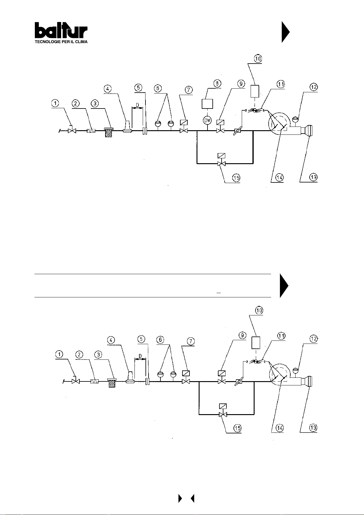
DIAGRAM FOR MODULA TING OR TWO-STAGE
PROGRESSIVE GAS AND DUAL FUEL BURNERS A T
NOMINAL THERMAL POWER > 2000 Kw
1 - Ball cock
2 - Anti-vibration joint
3 - Filter
4 - Gas pressure reducer ot stabilizer
5 - A couple of flange
6 - Minimum and maximum pressure switsc
7 - Safety valve
8 - Device to control valve seal and relative pressure switch DW
9 - Principle flame valve
10- Servomotore regulator delivery (gas-air)
1 1- Disc with screw to regulate air and gas delivery
12- Air pressure switch
13- Combustion head
14- Air regulation shutter
15- Ignition flame valve (pilot) with delivery regulator
D = Distance between pressure stabilizer and flange about 1,5 ÷ 2 m
N° 0002910610
DIAGRAM FOR MODULA TING OR TWO-STAGE PROGRESSIVE GAS AND
DUAL FUEL BURNERS AT NOMINAL THERMAL POWER < 2000 Kw
1 - Ball cock
2 - Anti-vibration joint
3 - Filter
4 - Gas pressure reducer or stabilizer
5 - A couple of flange
6 - Minimum and maximum pressure switch
7 - Safety valve
9 - Principle flame valve
10- Servomotore regulator delivery (gas-air)
1 1- Disc with screw to regulate air and gas delivery
12- Air pressure swit sh
13- Combustion head
14- Air regulation shutter
15- Ignition flame valve (pilot) with delivery regulator
D = Distance between pressure stabilizer and
flange about 1,5 ÷ 2 m
N° 0002910640
25
Page 26
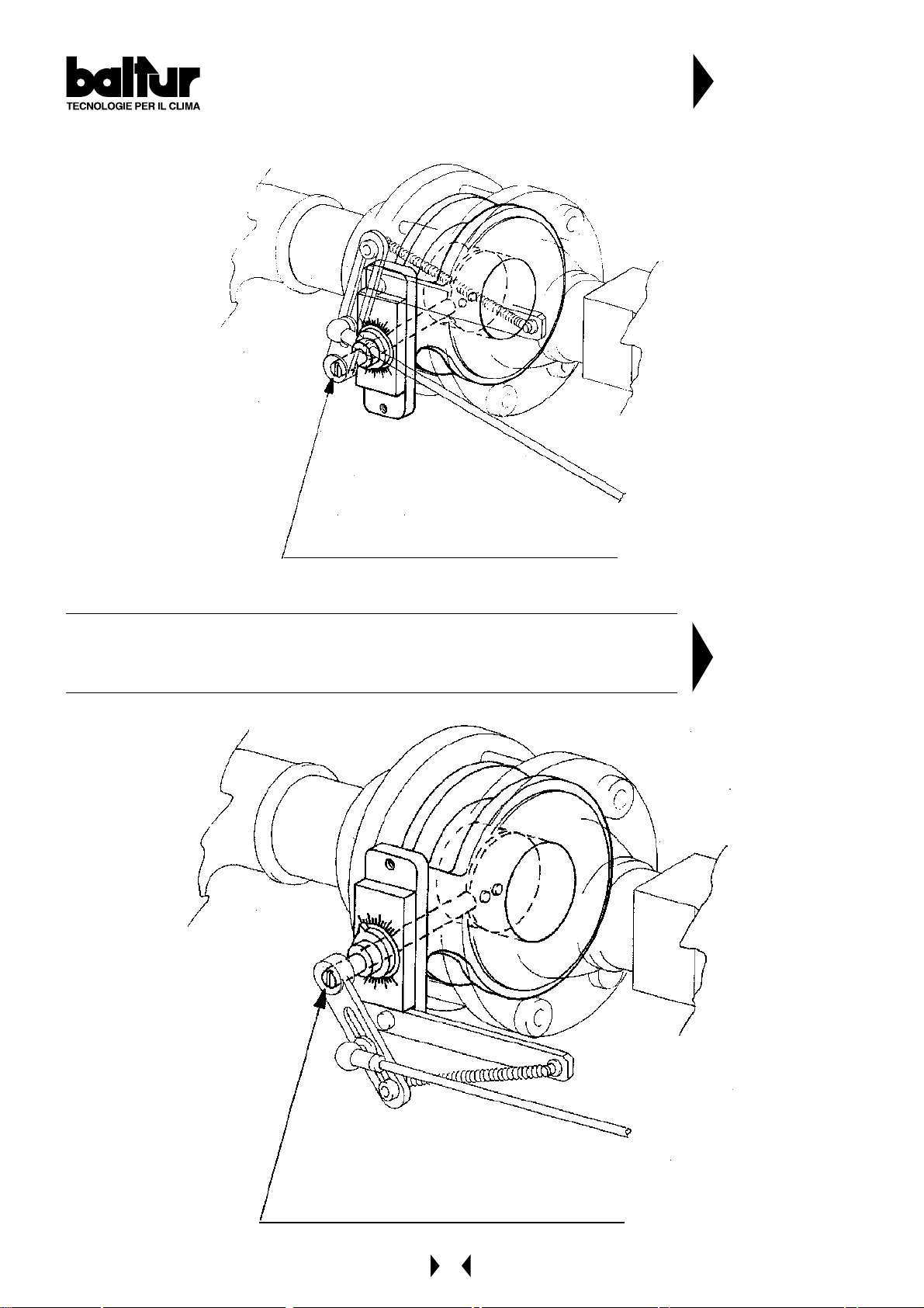
DETAILS ON THE REGULATION OF GAS
DELIVERY IN MODULATING BURNERS WITH
THROTTLE VALVE COMIST 72 - 122 DSP GM / MG
N° BT 8816/1
The notch shown on the end of the shaft indicates
the position pf the throttle valve (shutter)
DETAILS ON THE REGULATION OF GAS DELIVERY IN MODULATING
BURNERS WITH THROTTLE V ALVE
COMIST 180 - 250 - 300 DSPGM / DSPNM
N° BT 8813/1
The notch shown on the end of the shaft indicates
the position pf the throttle valve (shutter)
26
Page 27

ST ARTING UP AND REGULATION WITH LIGHT OIL
1) Check that the characteristics of the nozzle (delivery and spray angle) are suitable for the furnace
(see BT 9353/1). If not, replace it.
2) Check that there is fuel in the cistern and that it is, at least visually , suitable for the burner.
3) Check that there is water in the boiler and that the system’s gate valves are open.
4) Check, with absolute certainty, that the discharge of combustion products can take place freely (boiler and
chimney lock-gates should be open).
5) Make sure that the voltage of the electric line to which the burner is to be connected, corresponds to that
required by the manufacturer, and that the motors electrical connections have been correctly prepared to
match the voltage rating available. Also check that all the electrical connections carried out on the spot are in
accordance with our electric wiring diagram.
6) Make sure that the combustion head is long enough to enter the furnace to the extent specified by the boiler
manufacturer.
Check that the air regulation device on the combustion head is in the position considered necessary for the
fuel delivery required (the air passage between the disk and the head should be considerably closed when the
fuel delivery is relatively reduced; on the other hand, when the nozzle has a fairly high delivery , the air passage
between the disk and the head should be relatively open (see chapter “Regulation of the Combustion Head).
7) Remove the protective cover from the rotating disk inserted on the servomotor regulating delivery (fuel/air).
On this disk have been fitted adjustable screws which are used to control the fuel and the relative combustion
air.
8) Put the two modulating switches in the “MIN” (minimum) and “MAN” (manual) position.
9) Start up the fuel supply auxiliary circuit, check its efficiency and regulate the pressure at about 1 bar
(if the circuit is supplied with a pressure regulator).
10) Remove from the pump the vacuumeter connection point plug and then open slightly the gate valve fitted on
the fuel arrival pipe. Wait until the fuel comes out of the hole, without air bubbles, and then re-close the gate
valve.
11) Insert a manometer (end of the scale about 3 bar) into the vacuumeter connection point on the pump and
control the value of the pressure at which the fuel arrives at the burner pump. insert a manometer (end of the
scale 30 bar) into the manometer connection point provided on the pump and control its working pressure.
Insert a manometer (end of the scale about 30 bar) into the special connection point of the nozzle return
pressure regulator (see BT 8714/2) in order to control the return pressure.
12) Now open all the gate valves and any other interception devices fitted on the light oil pipelines.
13) Put the switch on the control panel in the “O” (open) position and give current to the electric lines which the
burner is connected to. Check, by pressing manually the relative relay, that the fan and pump motors rot ate in
the right direction. If they do not, exchange the places of two cables of the principle line in order to inverse the
sense of rotation.
14) St art operating the burner pump by pressing manually on the relative relay until the manometer, which measures
the working pressure of the pump, indicates a slight pressure. The presence of low pressure in the circuit
confirms that filling up has taken place.
15) Insert the switch on the control panel to give current to the control box. If the thermostats (safety and boiler)
are closed, the control box’s programmer will be connected and will insert the burner’s component devices
according to its pre-established programme. The unit start s up in this way , as described in Chapter “Description
of Operations”.
16) When the burner is operating at “minimum”, proceed with regulating the air to the quantity considered necessary
to ensure good combustion. Tighten more or loosen more the adjusting screws in correspondence to the point
of contact, with the lever which transmits the movement to the combustion air regulation shutter . It is preferable
that the quantity of air for the “minimum” is slightly reduced, in order to ensure a soft ignition even in the most
critical conditions.
17) After having regulated the air for the “minimum”, put the modulation switches in the “MAN” (manual) and
“MAX” (maximum) positions.
27
Page 28

18) The servomotor which regulates the fuel/air delivery starts moving; wait until the disk on which the regulating
screws have been fitted, has reached an angle of about 12° (this corresponds to a space taken up by three
screws), stop the modulation and return the switch to the “O” position. Carry out a visual control of the flame
and proceed, if necessary, with regulating the combustion air by operating as described in point 16.
Subsequently, control combustion with the appropriate instruments and modify, if necessary, the previous
regulation carried out by visual control only. The operation described above should be repeated progressively
(by moving forwards the disk by about 12° at a time) and modifying every time, if necessary , the fuel/air ratio
during the entire modulation run. Make sure that the increase in fuel delivery occurs gradually and that maximum
delivery is reached at the end of the modulation run. This is necessary in order to ensure that modulation
functions with good graduality. The positions of the screws that commend the fuel may need to be modified in
order to obtain the graduality required. Maximum delivery is obtained when the return pressure is about 2 ÷ 3
bar less than the delivery pressure (normally 20 ÷ 22 bar). For a correct air/fuel ratio, the percentage of Carbon
Dioxide (CO2) should increase with the increase in delivery (at least 10% at minimum delivery to a maximum
of 13% at maximum delivery). We advise against exceeding 13% of CO2 to avoid operating with a rather
limited excess of air which could cause a considerable increase in smoke opacity due to unavoidable
circumstances (a variation in the atmospheric pressure, presence of dust particles in the fan’s air ducts, etc.).
Smoke opacity depends on the type of fuel utilized (the most recent provisions indicate that it should not
exceed N° 2 of the Bacharach Scale). We advise, if possible, maintaining smoke opacity below N° 2 of the
Bacharach Scale, even if, as a consequence, the CO2 value is slightly lower. The lower smoke opacity dirties
the boiler less and therefore its average yield is normally high even when the CO2 value is slightly inferior.
It should be remembered that, in order to regulate properly, the water in the system should be at the right
temperature and the burner should have been operating for at least 15 minutes.
If the appropriate instruments are not available, judgement can be based on the colour of the flame.
We advise regulating in such a way as to obtain a flame bright orange in colour . Avoid a red flame with smoke
in it, or a white flame with an exaggerated excess of air. After having checked the air/fuel regulation, tighten the
locking screws of the adjustable screws.
19) Control that the modulation motor functions automatically by putting the AUT - O - MAN switch in the “AUT”
position and the MIN - O - MAX switch in the “O” position. In this way , modulation is activated exclusively by the
automatic command of the boiler’s probe, if the burner is a COMIST...MM (modulating) version, or on the
command of the thermostat or pressure switch of the 2nd stage, if the burner is a COMIST...DSPGN (two
stage progressive) version. (See Chapter “Electronic Potentiality Regulator RWF... for the modulating version).
Normally, it is not necessary to alter the internal settings of the Potentiality Regulator RWF... .
20) Check the efficiency of the flame detection device (photocell UV). The photoresistant cell is a flame control
device and, if the flame should be extinguished during operations, it must be capable of intervening (this
control should be made at least one minute after start up). The burner should be capable of blocking itself
(shut down), and remaining so, if the flame does not appear regularly during the start up phase within the time
limit preset on the control box. The shut down causes an immediate interception of the fuel, the burner comes
to a standstill and the red warning light comes on. To check the efficiency of the photocell UV and of the shut
down system, proceed as follows:
a) Start up the burner
b) after one minute, extract the photoresistant cell by pulling it out of its seat and simulate flame failure with
a dark cloth. The flame should be extinguished and the control box will repeat the ignition phase from the
beginning and, immediately after the flame appears, it will go to shut down.
c) The control box can only be unblocked by pressing manually on the appropriate pushbutton (unblocking).
To check the efficiency of the shut down device, carry out this control at least twice.
21) Check the efficiency of the boiler’s thermostats or pressure switches (this operation should stop the burner).
28
Page 29

REGULA TION OF THE COMBUSTION HEAD AND FLAME DISK (See BT 8608/1)
The burner is equipped with a combustion head which can be regulated (by moving it backwards or forwards) in
such a way as to close more or open more the air passage between the disk and the head.
By closing the passage, it is possible to achieve high pressure upstream the disk and therefore high velocity and air
turbulence for low inputs as well.
High velocity and air turbulence ensure a better penetration in the fuel and are therefore an optimum mixture and
allow the burner to operate with good flame stability .
High air pressure, upstream the disk, might be necessary in order to avoid flame pulsations, and it is considered
practically indispensable when the burner is operating with a pressurized furnace and/or high thermal load.
It is evident from above, that the position of the device which regulates the air on the combustion head should be put
in such a position as to always obtain a decidedly high air pressure value behind the disk.
It is advisable to regulate in such a way as to achieve a closing of the air between the disk and the head; this will
necessitate a considerable opening of the air shutter which regulates the flow to the burner’s fan suction.
Obviously these adjustments should be carried out when the burner is operating at maximum delivery desired.
In practice, commence regulating with the combustion head in an intermediate position, start up the burner and
make a first adjustment as previously described.
When maximum delivery desired has been reached, proceed with correcting the position of the combustion head;
move it backwards and forwards in such a way as to obtain an air flow suitable for the light oil delivery with the air
regulation shutter in suction considerably open.
It the combustion head is pushed forwards (which causes a reduction in the air passage between the head and the
disk), avoid closing it completely .
When regulating the combustion head, proceed with centering it perfectly with respect to the disk.
It must be pointed out that, if perfect centering with respect to the disk is not obtained, bad combustion and excessive
heating of the head could occur which would result in its rapid deterioration.
A control can be carried out by looking through the spy hole situated on the back of the burner.
Then tighten home the screws that lock the combustion head in position.
The distance between the disk and the nozzle, regulated by the manufacturer , must be reduced only it the atomized
fuel cone coming out of the nozzle wets the disk and fouls it.
Note: Check that ignition occurs regularly, because when the device has been moved forwards, it could occur that
the air velocity in exit is so high as to render ignition difficult.
If this happens, move it backwards, gradually , until it reaches the correct position and ignition occurs regularly.
This position should be definitive. It should be kept in mind that it is preferable, for the first flame, to limit the
amount of air to that strictly necessary in order to ensure safe ignition even in difficult circumstances.
29
Page 30

STARTING UP AND REGULATION WITH METHANE GAS
1) If not already done at the moment of connecting the burner to the gas pipeline, it is indispensable to carry out
a purge of the air contained in the pipeline. As a precaution, special care should be taken and doors and
windows should be opened. Open the pipe union on the pipeline situated near the burner and the open a little
the gas cut-off cock (or cocks). When the characteristic odour of gas can be smelled, close the cut-off cock.
Wait until the gas present in the room has dispersed, and then reconnect the burner to the gas pipeline.
Subsequently , re-open the gas cut-of f cock.
2) Check that there is water in the boiler and that the system’s gas valves are open.
3) Check, with absolute certainty that the discharge of combustion products can take place freely (boiler and
chimney lock-gates should be open).
4) Make sure that the voltage of the electric line to which the burner is to be connected, corresponds to that
required by the burner and that the electrical connections (motor or principle line) have been prepared to
match the voltage rating available. Also check that all the electrical connections carried out on the spot are in
accordance with our electric wiring diagram.
5) Make sure that the combustion head is long enough to enter the furnace to the extent specified by the boiler
manufacturer. Check that the device which regulates the air on the combustion head is in the position considered
necessary for the fuel delivery required (air passage between the disk and the head should be considerably
reduced when the fuel delivery is reduced; on the other hand, when the fuel delivery is fairly high; the air
passage between the disk and the head should be relatively open). See chapter “Air Regulation on the
Combustion Head”.
6) Apply a manometer with an adequate scale (if the entity of pressure forecast allows it; it is preferable to use a
column of water instruments, do not use a pointer instrument for moderate pressure) to the pressure plug on
the gas pressure switch.
7) Open, to the quantity considered necessary, the flow regulator incorporated in the ignition flame valve(s)
(pilot). If the burner is already working on light oil fuel, the combustion air regulation shutter must not be
modified; in such a case it will be necessary to adjust the gas flow to the amount of air already adjusted for the
light oil operation. If the burner is started up only on gas it is necessary to verify that the combustion air
regulation shutter is in the right position and, if not, to modify it by operating the adjustable screws of the
regulating disk.
8) Remove the protective cover from the disk on which are inserted the screws which regulate the gas and air
delivery , and unloosen the locking screws.
9) With the switch on the burner’s control panel in the “O” position and the main switch inserted check by manually
closing the relay, that the motor rotates in the right direction. If it does not, exchange the places of two cables
of the motor’s supply line in order to invert its sense of rotation.
10) Now insert the switch on the commend panel and put the modulating switches in the MIN (minimum) and MAN
(manual) positions. The control box receives voltage in this way and the programmer turns on the burner as
described in Chapter “Description of Operations”.
Note: Pre-ventilation is carried out with air open and, during this phase, the servomotor regulating the delivery
(gas/air) is inserted and completes the whole opening run until it reaches the “maximum” position.
Subsequently, the servomotor which regulates delivery (gas/air) returns to the starting position (minimum).
Only when modulation has returned to the “minimum” position, does the control box proceed with its ignition
programme and insert the transformer and the gas ignition valves (pilot). During the pre-ventilation phase
check that the air pressure switch effects a changeover (it should pass from a closed position without
measurement of pressure to a closed position with measurement of air pressure).
If the air pressure switch does not measure sufficient pressure (it will not effect the changeover) and neither
the ignition transformer nor the gas ignition flame valves will be inserted and the control box will go to “shut
down”. It should be pointed out that “shut downs” during the first ignition phase are considered normal. This
is because air still exists in the pipeline of the valve incline and must be expelled before it is possible to have
a stable flame. To unblock the control box, press the relative pushbutton.
30
Page 31

UV CELL
If the flame detection is carried out with the UV cell, the following should be taken into consideration.
Even the slightest greasiness will compromise the passage of the ultraviolet rays through the UV photoelectric
cell bulb, thus preventing the sensitive internal element from receiving the quantity of radiation necessary for
it to function properly . Should the bulb be fouled by light oil, fuel oil, etc., it is indispensable to clean it thoroughly .
It should be pointed out that even by simply touching the bulb with the fingers, it is possible to leave a slight
greasiness which could compromise the working of the UV photoelectric cell. The UV cell does not “see”
daylight or light from an ordinary lamp. It is possible to verify its sensibility with a flame (or cigarette lighter or
a candle) or with the electric spark that occurs between electrodes in an ordinary ignition transformer .
To ensure that the UV cell works properly, its current value should be suf ficiently st able so as not to fall below
the minimum value required for the specific control box. It may be necessary to search experimentally for the
best position by sliding (axial or rotation movement) the body that contains the photoelectric cell in respect to
the fastening clamp. An inspection can be carried out by inserting a microammeter , with an adequate scale, in
series to one of the two UV photoelectric cell connection wires. It is obviously necessary to respect the polarity
+ and -). For the LFL.... control box, the value of the cell current should be from 70 microamperes to 630
microamperes (the value is shown on the wiring diagram).
11) With the burner operating at a minimum (ignition flame valve and safety valve open and servomotor which
regulates delivery (gas/air) at a minimum), immediately check visually the entity and appearance of the flame
and, if necessary , proceed with correcting it by operating the gas delivery regulator of the ignition flame (pilot)
and/or the adjustable screws of the disk which regulates the gas and air delivery. Subsequently, check the
quantity of gas delivered by reading the meter. See Chapter “Reading the meter”.
If necessary, correct the gas and relative combustion air delivery by operating as described in point 7. The
control combustion with the appropriate instruments. For a correct air/gas ratio, the percentage of Carbon
Dioxide (CO2) should increase together with the increase in delivery. As an indication, for methane gas, the
percentage should be from at least 8 % at minimum burner delivery to an optimum value of 10 % for maximum
delivery. We advise against exceeding the value of 10 % to avoid operating with a rather limited excess of air
which could cause (variation in atmospheric pressure, presence of dust particles in fan’s air ducts) a considerable
amount of Carbon Monoxide (CO). It is indispensable to check, with the appropriate instrument, that the Carbon
Monoxide (CO) present in the smoke does not exceed the maximum level permitted of 0,1 %.
12) After having regulated at “minimum”, put the modulation switches in the “MAN” (manual) and “MAX” (maximum)
positions.
13) The servomotor regulating fuel/air delivery starts up; wait until the disk on which the regulating screws have
been fitted, has reached an angle of about 12° (this corresponds to the space taken up by three screws), and
then stop modulation and return the switch to the “O” position. Carry out a visual control of the flame and
proceed, if necessary , with regulating the combustion air and the gas by operating the adjustable screws of the
regulating disk. The operation described above should be repeated progressively (by moving forward the disk
about 12° at a time) and modifying every time, if necessary , the fuel/air ratio during the whole modulation run.
Make sure that the increase in fuel delivery occurs gradually and that maximum delivery is reached at the end
of the modulation run. This is necessary in order to ensure that the modulation functions with good graduality.
The positions of the screws that commend the fuel may need to be modified in order to obtain the graduality
required.
14) With the burner operating at maximum delivery required for the boiler, check combustion with the appropriate
instruments and modify , if necessary , the previous regulation carried out af ter a visual control only (CO2 max. =
10 % CO max. = 0,1 %).
15) We recommend controlling the combustion with the appropriate instruments and, if necessary, modify the
previous regulation carried out, after a visual control only, also in a few intermediate points of the modulation
run.
16) Check that modulation functions automatically by putting the AUT - O - MAN switch in the “AUT” position and
the MIN - O - MAX switch in the “O” position. In this way , modulation is activated exclusively by the automatic
command of the boiler’s probe, if the burner is a COMIST ....MM (modulating) version, or on the command of the
thermostat or pressure switch of the 2nd stage, if the burner is a COMIST...DSPGN (two-stage progressive)
version. (See Chapter “Electronic Potentiality Regulator RWF ... for the modulating version).
31
Page 32

17) The air pressure switch has the job of bringing the control box to a safety shut down if the air pressure is not at
the correct value. Therefore, the air pressure switch must be regulated in such a way as to intervene by closing
the contact (foreseen to be closed while working) when the air pressure in the burner has reached a sufficient
level. The pressure switch is self-controlled and therefore it must close the contact (fan stops and consequently
there is an absence of air pressure in the burner; if it does not, the control box will not be inserted (the burner
remains at a standstill). It must be specified that if the contact is not closed during working (insufficient air
pressure), the control box will carry out its cycle, but the ignition transformer will not be inserted and the gas pilot
valves will not open. Consequently, the burner will go to “shut down”. Check that the air pressure switch functions
properly with burner at minimum delivery , increase the regulating valve until it reaches intervention point and the
burner should go to shut down. To unblock the burner, press the special pushbutton and return the pressure
switch regulator to a sufficient value in order to measure the air pressure existing during the pre-ventilation
phase.
18) The pressure switches which control the gas pressure (minimum and maximum) have the job of stopping the
burner functioning when the gas pressure is not within the values specified. From the specific functions of the
pressure switches, it is evident that the pressure switch which controls the minimum pressure must make use
of the contact, which is closed, when it measures a pressure which exceeds that at which it has been set.
The maximum pressure switch must make use of the contact, which is closed, when it measures a pressure
below that at which is has been set. The minimum and maximum gas pressure switches should be regulated
during the burner’s general inspection and should be in function with the pressure found each time.
The pressure switches have been electrically connected in series and therefore the intervention (by this mean
the opening of the circuit) of any one of the gas pressure switches, will prevent the control box and thus the
burner from starting up. When the burner is operating (flame lit), the intervention of the gas pressure switches
(opening of the circuit) determines the immediate arrest of the burner. During the burner’s general inspection,
check the correct functioning of the pressure switches. By operating the respective regulating device, it is
possible to control the pressure switch’s intervention (opening of circuit) which causes the burner’s arrest.
19) Check the efficiency of the flame detector “UV photoelectric Cell” sliding it put of its seat on the burner and verify
the “shut down”.
20) Check the efficiency of the thermostats and pressure switches (this should result in the burner coming to a
standstill).
32
Page 33
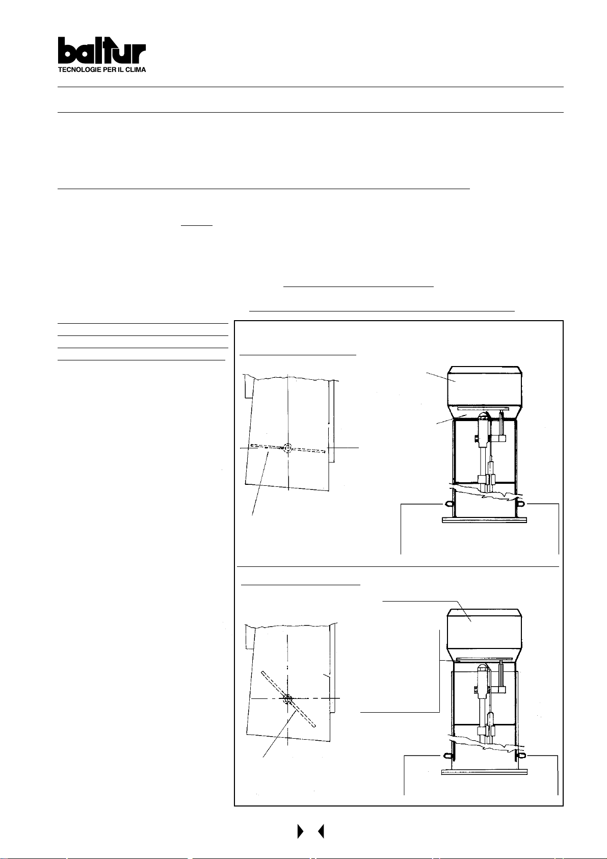
REGULA TION OF THE COMBUSTION HEAD AND FLAME DISK (See BT 8608/1)
The burner is equipped with a combustion head which can be regulated (by moving it backwards or forwards) in
such a way as to close more or open more the air passage between the disk and the head.
By closing the passage, it is possible to achieve high pressure upstream the disk and therefore high velocity and
air turbulence for low inputs as well. High velocity and air turbulence ensure a better penetration in the fuel and are
therefore an optimum mixture and allow the burner to operate with good flame stability .
High air pressure, upstream the disk, might be necessary in order to avoid flame pulsations, and it is considered
practically indispensable when the burner is operating with a pressurized furnace and/or high thermal load.
It is evident from above, that the position of the device which regulates the air on the combustion head should be
put in such a position as to always obtain a decidedly high air pressure value behind the disk.
It is advisable to regulate in such a way as to achieve a closing of the air between the disk and the head; this will
necessitate a considerable opening of the air shutter which regulates the flow to the burner’s fan suction.
Obviously these adjustments should be carried out when the burner is operating at maximum delivery desired.
In practice, commence regulating with the combustion head in an intermediate position, start up the burner and
make a first adjustment as previously described. When maximum delivery desired has been reached, proceed
with correcting the position of the combustion head; move it backwards and forwards in such a way as to obtain
an air flow suitable for the light oil delivery with the air regulation shutter in suction considerably open.
It the combustion head is pushed
forwards (which causes a reduction in
the air passage between the head and
the disk), avoid closing it completely.
When regulating the combustion head,
proceed with centering it perfectly with
respect to the disk. It must be pointed
out that, if perfect centering with
respect to the disk is not obtained, bad
combustion and excessive heating of
the head could occur which would
result in its rapid deterioration.
A control can be carried out by looking
through the spy hole situated on the
back of the burner.
Then tighten home the screws that lock
the combustion head in position. The
distance between the disk and the
nozzle, regulated by the manufacturer,
must be reduced only it the atomized
fuel cone coming out of the nozzle wets
the disk and fouls it.
Note: Check that ignition occurs
regularly, because when the
device has been moved
forwards, it could occur that the
air velocity in exit is so high as
to render ignition difficult. If this
happens, move it backwards,
gradually, until it reaches the
correct position and ignition
occurs regularly. This position
should be definitive.
It should be kept in mind that it
is preferable, for the first flame,
to limit the amount of air to that
strictly necessary in order to
ensure safe ignition even in
difficult circumstances.
GENERAL DIAGRAM AIR REGULA TION
INCORRECT REGULA TION
Combustion head
Combustion air inlet with
very locked shutter
CORRECT REGULA TION
Combustion air inlet with
very opened shutter
Air flow large
opening
Control and fixing knobs
of combustion head
Combustion head
Air flow
quite locked.
Attention:
Avoid complete
locking
Control and fixing knobs
of combustion head
N° BT 8608/1
33
Page 34

READING GAS (METHANE) METER
When the burner is operating at maximum output, check that the quantity of gas delivered is necessary for the
boiler’s needs. The low calorific value for methane gas is about 8550 kcal/m3.
To find out the low calorific values of other types of gas, contact the Gas Distributing Company . Delivery per hour
should be taken at the meter. When checking delivery make sure that gas is not being consumed by other users.
If the gas delivery pressure at the meter is not above 400 mm.w.c., t ake into consideration the value indicated by
the meter without correcting it.
For a first indication, turn on the burner and when it arrives at nominal delivery, measure the gas output in one
minute exactly (the difference between the two readings should be one minute exactly from one to the other .
Multiply this value by 60 in order to obtain the output for 60 minutes (one hour).
The output measured is considered the actual value if the meter reads a pressure below 400 mm.w.c. If the
pressure is more than 400 mm.w.c., the value read must be multiplied by a correction coefficient, as previously
described. Subsequently, multiply the delivery per hour (m3/h) by the gas calorific value to obtain the potentiality
delivered in kcal/h; this should correspond or be very near to that requested for the boiler (low calorific value for
methane gas = 8550 kcal/m3).
Do not allow the burner to operate for a long time (only a few minutes) if the output exceeds the maximum allowed
for the boiler, to avoid possible damage to it; it would be timely to stop the burner immediately after having taken
the two meter readings.
Correcting the value indicated by the meter If the meter measures the gas delivery at a pressure above 400
mm.w.c., it is necessary to multiply the value by a correction coef ficient.
As an indication, the correction coefficient values to be adopted in function with the gas pressure existing at the
meter, can be determined in the following way:
Add to number 1 (one) the number which expresses the gas pressure value in bar, existing at the meter.
Example n°1
Gas pressure at the meter = 2 bar, the multiplication coef ficient is 1 + 2 = 3.
Therefore, if the meter reads a delivery of 100 m3/h, multiply it by 3 to obtain the actual output which is
100 m3/h x 3 = 300 m3/h.
Example n°2
Gas pressure at the meter = 1,2 bar, the multiplication coefficient is 1 + 1,2 = 2,2.
Therefore, if the meter reads a delivery of 100 m3/h, multiply it by 2,2 to obtain the actual output which is
100 m3/h x 2,2 = 220 m3/h.
Example n° 3
Gas pressure at the meter = 0,3 bar, (3000 mm.w.c.), the multiplication coefficient is 1 + 0,3 = 1,3.
Therefore, if the meter reads a delivery of 100 m3/h, multiply it by 1,3 to obtain the actual output which is
130 m3/h.
Example n°4
Gas pressure at the meter = 0,3 bar, (600 mm.w.c.), the multiplication coefficient is 1 + 0,06 = 1,06.
Therefore, if the meter reads a delivery of 100 m3/h, multiply it by 1,06 to obtain the actual output which is
100 m3/h x 1,06 = 106 m3/h.
34
Page 35
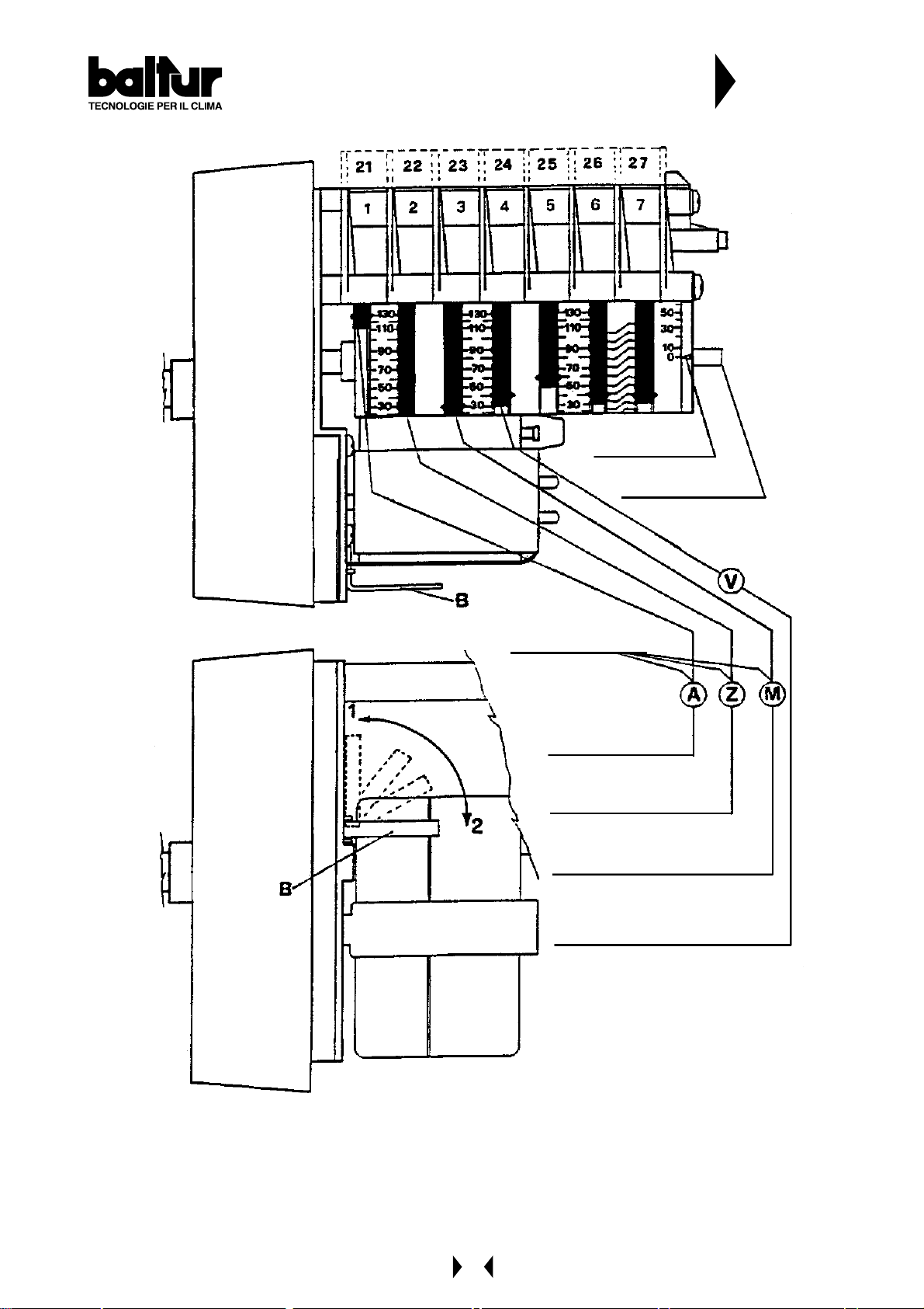
DET AILS OF THE MODULATION CONTROL
MOTOR SQM 10 - SQM 20 FOR REGULATING
CAMS OF GAS AND MIXER BURNERS
Reference index
Cam shaft
N° BT 8562/1
Adjustable cams
Maximum opening
end of the run
Total air closure
(burner at a standstill)
Air ignition opening
Principle feed valve(s)
B = Insertion and disinsertion lever
Motor connection - camshaft
Position 1 = Disinsertion
Position 2 = Insertion
To modify the regulation of the cams utilized, operate the respective red rings (A - Z - M - V).
By pushing with enough force, in the direction desired, each red ring will rotate with respect to the reference scale.
The index of the red ring indicates on the respective reference scale the rotation angle taken up foe each cam.
35
Page 36
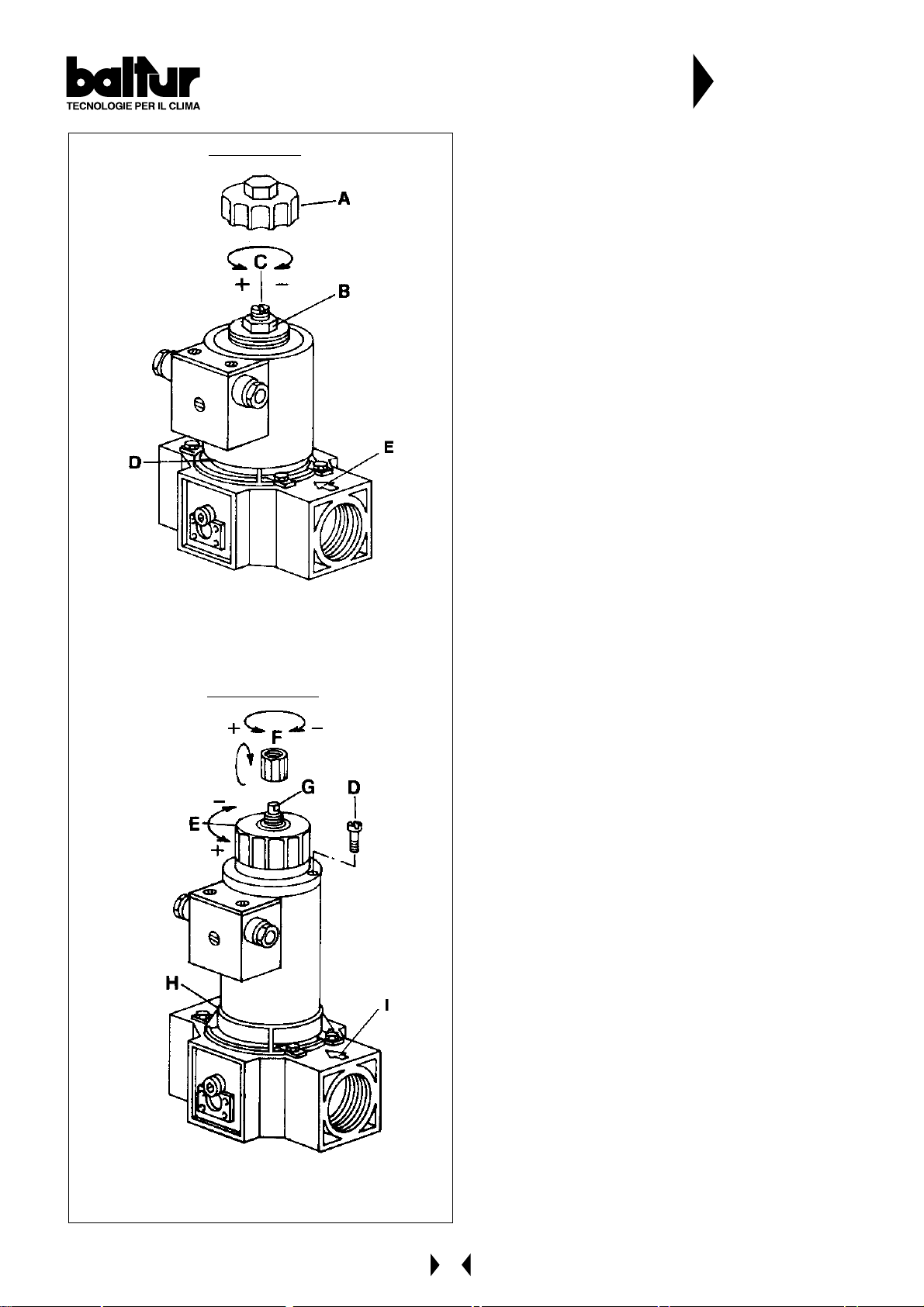
INSTRUCTIONS FOR SETTING DUNGS GAS
VALVES mod. MVD ... and MVDLE ...
Mod. MVD....
D = Identification plate
E = Flow direction indicator
Mod. MVDLE....
N° 8875-GB
Rev. 06/11/90
8875.tif
The MVD gas valves open and close rapidly .
To regulate the gas flow, unscrew and remove cap
“A” and loosen nut “B”.
Then, using a screwdriver turn screw “C”.
Unscrewing it increases the gas flow, tightening it
decreases the flow.
After regulating, lock nut “B” in place and reposition
cap “A”.
HOW THE VALVE FUNCTIONS mod. MVDLE
The gas valve has a rapid initial trip (opening can be
adjusted from 0 to 40% using pin “G”). Full opening
from that point on takes place slowly over
approximately 10 seconds.
N.B. There will not be sufficient supply for ignition if
the flow feed device “E” is set at its minimum
position. Therefore, it is essential to open the
maximum flow rate control device “E” sufficiently
to ensure ignition.
Setting the initial rapid release trip
T o set the initial rapid release, unscrew the protection
cap “F” and use the back of this cap as a tool to turn
pin “G”.
Turning clockwise decreases the gas flow, turning
counter-clockwise increases it.
This done, return cap “F” to its original position.
H= Identification plate
I = Flow direction indicator
Setting maximum gas flow
To adjust the gas flow rate, loosen screw “D” and
turn knob “E”. Turning clockwise decreases the gas
flow, turning counter-clockwise increases it.
This done, tighten screw “D”.
36
Page 37
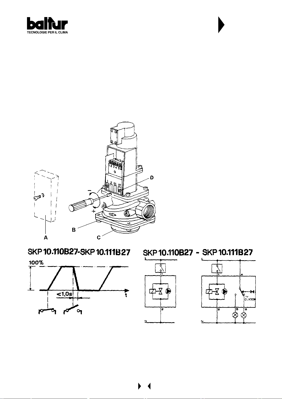
INSTRUCTIONS FOR SETTING LANDIS & GYR
mod. SKP 10.110 B27 - SKP 10.111B27
SINGLE ST AGE GAS VALVES
DESCRIPTION OF HOW THE VA LVE OPERATES
Single-stage valves
When the valve receives the signal to open, the pump cuts in and the magnetic valve closes. The pump
transfers the oil from under the piston to above it, forcing the piston downward, which compresses the closure
return spring with the rod and plate. The valve remains in the open position while the pump and magnetic valve
remain powered. When the unit receives the signal to close (or if power supply is cut off) the pump shuts down,
the magnetic valve opens decompressing the chamber above the piston. The plate is closed both by the return
spring and by gas pressure. The flow rate for this valve is calculated to ensure full closure in less than one
second.
This type of valve cannot regulate the gas flow
rate (closure/opening).
Screw “D” on terminal “IV” sets the “clean
contact” position which can be used for an
outside signal.
N° 8880
Rev. 06/11/90
A = Driver identification plate
B = Flow direction indicator
C = V alve body identification plate
37
Page 38
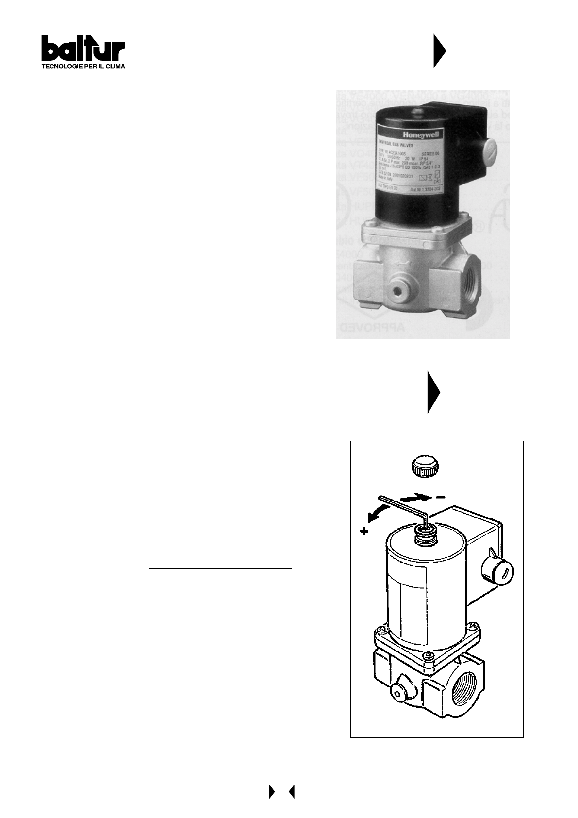
INSTRUCTIONS FOR HONEYWELL GAS
VALVES UNIVERSAL GAS VALVES TYPE: VE
4000A1 (....A .... = Opening - Closure, rapid)
The VE 4000A1 valves are Class A solenoid valves, normally
closed. They may be used as ON/OFF valves in the supply
trains with Natural Gas, Manufactured Gas or GPL, on burners
or combustion installations.
They are provided with M.I. and CE Approval for EN161.
FEATURES
- V alves normally closed
- Without flow regulator
- Rapid opening and closing
N° 0002910370
Rev . 25/06/96
02910370.tif
INSTRUCTIONS FOR HONEYWELL GAS VALVES UNIVERSAL GAS
VALVES TYPE: VE 4000B1 (....B.... = Opening - Closure, rapid. Flow
regulator)
FEATURES
- Valve normally closed
- With flow regulator
- Rapid opening and closing
The VE4000B1 valves are Class A solenoid valves, normally
closed. They may be used as ON/OFF valves in the supply trains
with Natural Gas, Manufactured Gas or GPL, on burners or
combustion plants.
They are provided with M.I. and CE Approval for EN 161.
ADJUSTMENT
For models VE 4000B1 (see fig. 1)
Adjustment to the flow
- Remove the cover from the upper section of the coil.
- Insert a hexagonal Allen key into the central section at the top.
- Turn clockwise to decrease the flow or anti-clockwise to increase it.
- Replace the cover and tighten it.
ATTENTION
- The adjustment must only be carried out by qualified personnel.
- Per la chiusura della valvola è necessario che la tensione ai termi-
nali della bobina sia 0 volt.
- The flow regulator of the VE 4100 valve series is situated in the
lower section.
fig.1
N° 0002910380
Rev . 13/10/95
02910380a.tif
38
Page 39

CONTROL BOX FOR LFL 1...
SERIES 02 GAS BURNERS
Control box for burners of average and high power, with forced draught, intermittent service (*), 1 or 2
stages, or modulating types, with supervision of the air pressure for controlling the air damper .
This control box bears the EC mark, in accordance with the Gas and Electromagnetic Compatibility Directive.
* For reasons of safety, it is necessary to make at least one controlled stop every 24 hours!
As regards the standards
The following LFL1… features exceed the standards, offering a high level of additional safety:
- The flame detector test and false flame test start immediately after the tolerated post-combustion time. If the
valves remain open, or do not close completely after adjustment stops, a lock-out stop is triggered at the end of the
tolerated post-combustion period. The tests will end only at the end of the pre-ventilation time of the next start-up.
- The validity of working of the flame control circuit is checked each time the burner starts up.
- The fuel valve control contacts are checked for wear during the post-ventilation time.
- A built-in fuse in the appliance protect s the control cont act s from any overloads that may occur.
As regards the burner control
- The equipment allows operation with or without post-ventilation.
N° 7451
Rev . 10/1997
- Controlled activation of the air damper to ensure pre-ventilation with nominal airflows. Positions checked: CLOSED
or MIN (position of ignition flame on start-up); OPEN at the beginning and MIN at the end of the pre-ventilation
time. If the servomotor does not position the air damper at the points described, the burner does not start-up.
- Ionization current minimum value = 6mA
- UV cell current minimum value = 70mA
- Phase and neutral must not be inverted.
- Any place may be used for installation and assembly (IP40 protection).
39
Page 40
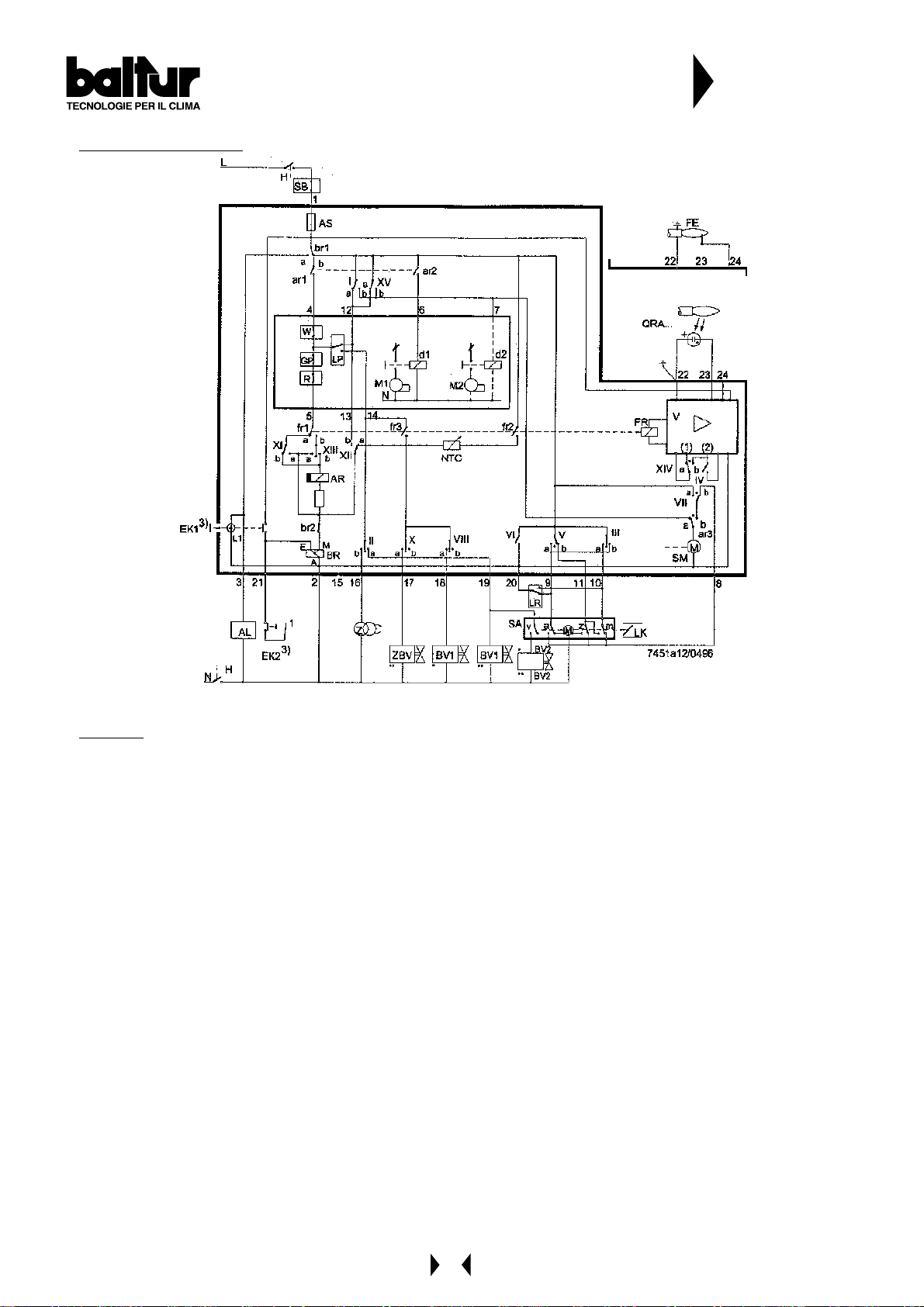
Electrical connections
CONTROL BOX FOR LFL 1...
SERIES 02 GAS BURNERS
N° 7451
Rev . 10/1997
The burner manufacturer’s diagram is valid for the relief valve connections.
LEGEND
For the entire catalogue sheet
a Limit switch commutation contact for air damper
OPEN position
AL Remote signalling of lock-out stop (alarm)
AR Main relay (operating relay) with “ar…” contacts
AS Appliance fuse
BR Lock-out relay with “br…” contacts
BV Fuel valve
bv... Control contact for gas valve CLOSED position
d… Remote control switch or relay
EK… Lock-out push-button
FE Ionization current probe electrode
FR Flame relay with “fr…” contacts
GP Gas pressure switch
H Main switch
L1 Fault indicator light
L3 Ready for operation indicator
LK Air damper
LP Air pressure switch
LR Power regulator
m Auxiliary commutation contact for air damper
MIN position
M… Motor fan or burner
NTC NTC resistor
QRA.. UV probe
R Thermostat or pressure probe
RV Fuel valve with continuous regulation
S Fuse
SA Air damper servomotor
SB Safety limiter (temperature, pressure, etc.)
SM Programmer synchronous motor
v In the case of servomotor: auxiliary contact for
consensus for fuel valve depending on air damper
position
V Flame signal amplifier
W Thermostat or safety pressure switch
z In the case of servomotor: limit switch
commutation contact for air damper CLOSED
position
Z Ignition transformer
ZBV Pilot burner fuel valve
• Valid for forced draught burners, with obe tube
•• Valid for pilot burners with intermittent operation
(1) Input for increasing operating voltage for UV probe
(probe test)
(2) Input for forced energizing of flame relay during
functional test of flame supervision circuit (contact
XIV) and during safety time t2 (contact IV)
3
) Do not press EK for more than 10 seconds
40
Page 41
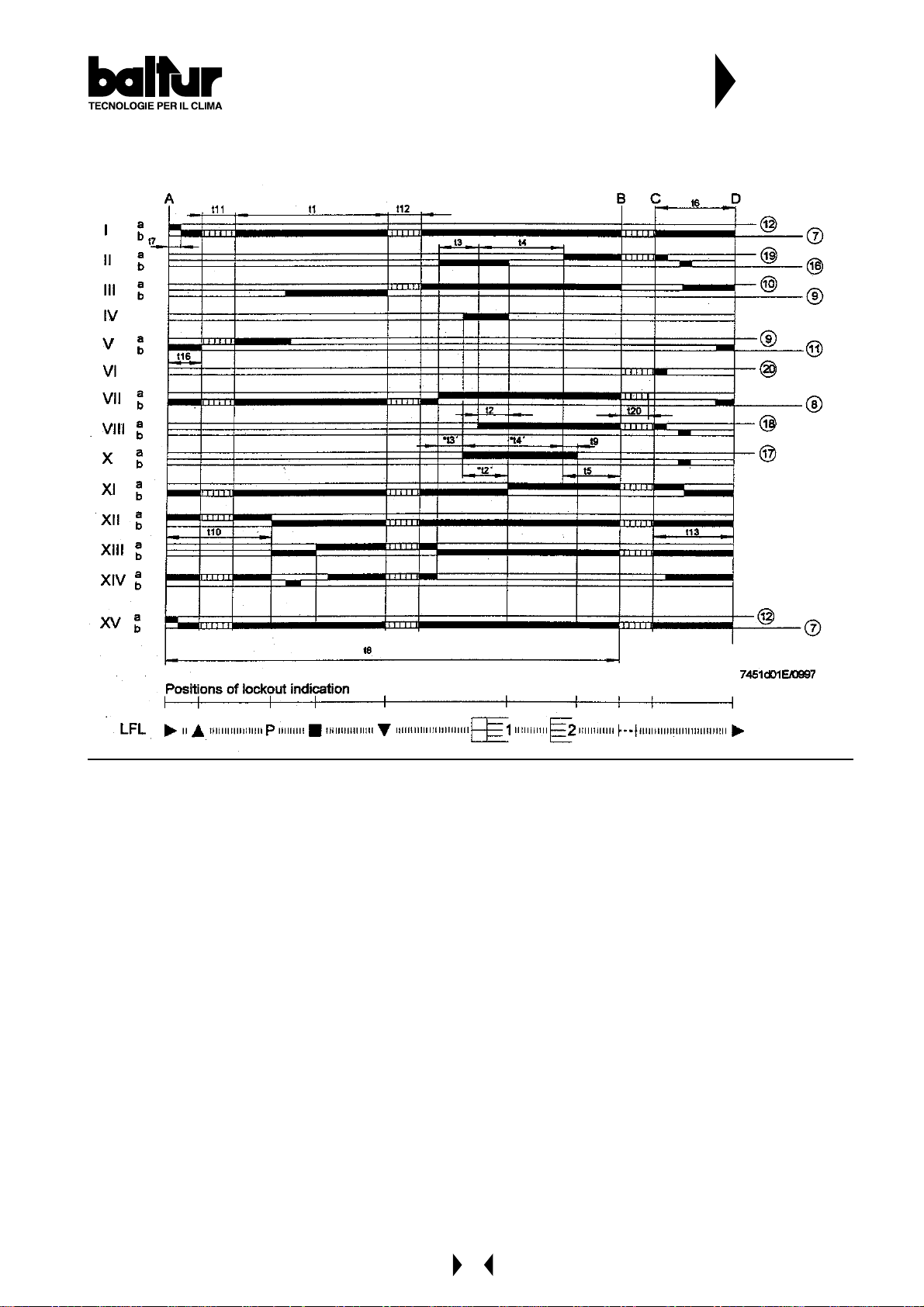
Notes on the programmer
Programmer sequence
CONTROL BOX FOR LFL 1...
SERIES 02 GAS BURNERS
N° 7451
Rev . 10/1997
Output signals on terminals
Times Legend
time (50 Hz) in seconds
31.5....... t1 Pre-ventilation time with air damper open
3............ t2 Safety time
- ............ t2' Safety time or safety time with burners that use pilot burners
6............ t3 Short pre-ignition time (ignition transformer on terminal 16)
- ............ t3' Long pre-ignition time (ignition transformer on terminal 15)
12.......... t4 Time between beginning of t2' and valve consensus on terminal 19 with t2
- ............ t4' Time between beginning of t2' and valve consensus on terminal 19
12.......... t5 Time between end of t4 and consensus at power regulator or at valve on terminal 20
18.......... t6 Post-ventilation time (with M2)
3............ t7 Time between consensus for start-up and voltage at terminal 7 (start delay for fan motor M2)
72.......... t8 Start-up duration (without t11 and t12)
3............ t9 Second safety time for burners that use pilot burners
12.......... t10 Time from start-up to beginning of air pressure control without air damper travel time
t11 Air damper opening travel time
t12 Air damper in flow flame position (MIN) travel time
18.......... t13 Permitted post-combustion time
6............ t16 Initial delay of consensus for air damper OPENING
27.......... t20 Time up to automatic closure of programmer mechanism after burner start-up
NOTE: With voltages at 60 Hz, the times are reduced by about 20%.
41
Page 42

CONTROL BOX FOR LFL 1...
SERIES 02 GAS BURNERS
t2', t3', t3':
These times are valid only for series 01 or LFL1.335, LFL1.635, LFL1.638 burner control and command
equipment.
They are not valid for types of Series 032, since they involve simultaneous activation of cams X and VIII.
Working
The above diagrams illustrate both the connection circuit and the sequencer mechanism control program.
A Consensus for start-up by means of installation thermostat or pressure switch “R”.
A-B Start-up program
B-C Normal burner operation (on the basis of “LR” power regulator control commands)
C Stop controlled by “R”
C-D Return of programmer to start-up position “A”, post-ventilation.
During periods of inactivity of the burner, only the command output s 11 and 12 are powered, and the air
damper is in the CLOSED position, determined by limit switch “z” of the air damper servo motor. During the
probe test and false flame test, the flame supervision test is also powered (terminals 22/23 and 22/24).
N° 7451
Rev . 10/1997
Safety standards
• In association with the use of QRA…, earthing of terminal 22 is compulsory.
• The power cables must conform to existing national and local standards.
• LFL1… is a safety device, and it is therefore forbidden to open it, tamper with it or modify it!
• The LFL1… device must be completely insulated from the mains before carrying out any operations on it!
• Check all the safety functions before activating the unit or after replacing a fuse!
• Provide protection against electric shock on the unit and all electric connections. This is ensured by
following the assembly instructions correctly!
• During operation and maintenance, prevent infiltration of condensate into the command and control
equipment.
• Electromagnetic discharges must be checked on the application plan.
42
Page 43
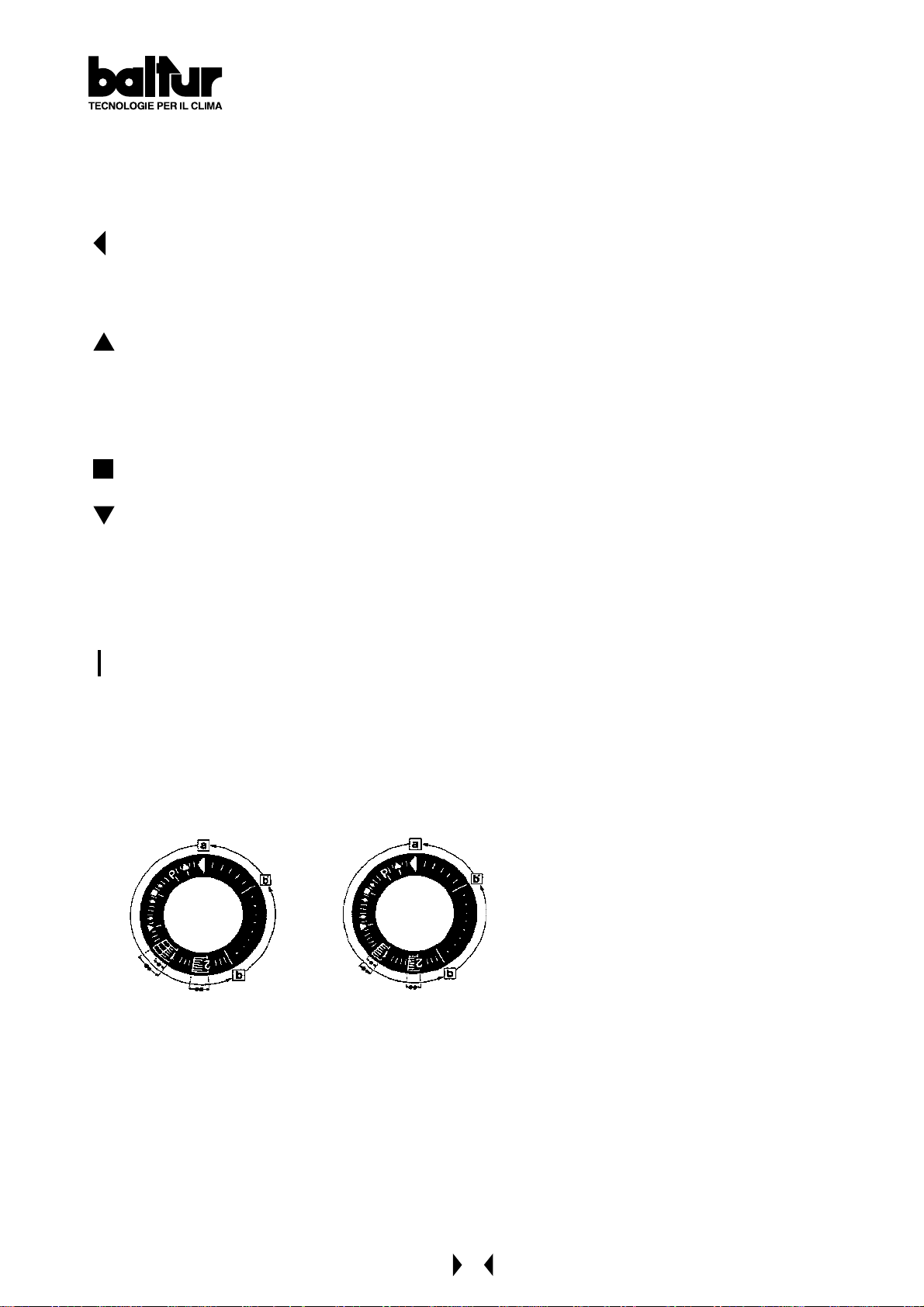
CONTROL BOX FOR LFL 1....
SERIES 02 GAS BURNERS
Control program in the event of stopping, indicating position of stop
As a rule, in the event of any kind of stop, the fuel flow is cut off immediately. At the same time, the
programmer remains immobile, as does the switch position indicator. The symbol visible on the indicator
reading disk indicates the type of fault.
No start-up, because of failure in closing of a contact or lock-out stop during or at the end of the
command sequence because of external lights (for example: flames not extinguished, loss at the level
of the fuel valve, defects in the flame control circuit, etc.)
Start-up sequence stops , because the OPEN signal was not sent to terminal 8 by limit switch contact
“a”. Terminals 6, 7 and 15 remain powered until the defect is eliminated.
Rev . 10/1997
P Lock-out stop, because of lack of air pressure signal.
Any lack of pressure from this moment onwards will cause a lock-out stop!
Lock-out stop because of flame detection circuit malfunction.
Start-up sequence stops , because the position signal for low flame was not sent to terminal 8 by
auxiliary switch “m”. Terminals 6, 7 and 15 remain powered until the fault is eliminated.
N° 7451
1 Lock-out stop, due to lack of flame signal at the end of the first safety time.
2 Lock-out stop, because no flame signal was received at the end of the second safety time (main lame
signal with pilot burners at intermittent operation).
Lock-out stop, due to lack of flame signal during burner operation.
If a lock-out stop occurs at any moment between the start and pre-ignition without a symbol, the cause is
generally to be attributed to a premature or abnormal flame signal caused, for example, by self-ignition of a
UV tube.
Stop indications
a-b Start-up program
b-b’ “Trips” (without contact confirmation)
b(b’)-a Post-ventilation program
LFL …, Series 01 LFL …, Series 02
43
Page 44

LDU 1 1.. GAS VALVE TIGHTNESS CONTROL EQUIPMENT
Use
LDU 1 1 equipment is used to verify tightness of valves on natural gas burners.
The LDU 1 1 combined with a normal pressure switch automatically verifies tightness of natural gas burners valves,
before every start up and immediately after each stop. T ightness control is carried out by two-st age verification of
gas circuit pressure in the section between the two burner valves.
Operation
During the first stage of the tightness control (TEST 1), the pipeline between the valves being checked must be at
atmospheric pressure. In plant without atmospheric pressure setting pipes, this pressure is achieved by tightness
control equipment. The latter opens the valve on the furnace side for 5 seconds during “t4” time.
When the 5 seconds are up, the furnace side valve is closed. During the first phase (TEST 1) the control equipment
ensures that atmospheric pressure in the pipes is kept constant.
Surveillance is carried out by the “DW” thermostat.
If there is blow-by in the safety valve while closing, pressure increases and as a result the “DW” pressure switch
operates. For this reason, in addition to indicating pressure, the equipment goes into fault state and the position
indicator stops blocked in the “TEST 1” position (red pilot lamp lit).
Vice-versa, if pressure does not increase because there is no blow-by in the relief valve as it closes, the equipment
immediately programmes the second stage “TEST 2”.
Under these conditions, the relief valve opens for 5 seconds during “t3” time and introduces gas pressure into the
pipeline (“filling operation”). During the second verification stage, this pressure must remain constant.
Should it drop, this means that the burner on the furnace side has a blow-by (fault) when closing.Therefore the
“DW” pressure switch operates and the tightness control equipment prevents burner start-up and stops in blocked
state (red pilot lamp lit). If second stage verification is positive, the LDU 11 equipment closes the internal control
circuit between terminals 3 and 6 (terminal 3 - contact ar2 - outer cross-connection for terminals 4 and 5 - contact
III - terminal 6). This is the circuit that usually enables the equipment start-up control circuit. After circuit between
terminals 3 and 6 has closed, the LDU 11’s programmer returns to rest position and stops. This means it enables
fresh verification without changing the position of the programmer’s control contacts.
N.B. Adjust the “DW” pressure switch to about half the pressure of the gas supply network.
Key to symbols:
} St art-up = operating position
In plants without a bleed valve = test circuit put under atmospheric pressure by opening of valve on the
furnace side of the burner.
TEST 1 “TEST 1” pipeline at atmospheric pressure (blow-by verification at closure of relief valve)
Putting test circuit gas under pressure by opening of relief valve
TEST 2 “TEST 2” pipeline at gas pressure (blow-by verification of valve on furnace side of burner)
III Automatic zero (or inoperative mode) reset of programmer
} Operation = set for new blow-by verification
If trouble is signalled, there is no voltage in all control equipment terminals excepting terminals 13 which gives
remote, visual indication of trouble.
When verification is over, the programmer automatically returns to rest position, and is ready to carry out a further
programme for checking tightness of valves as they close.
44
Page 45
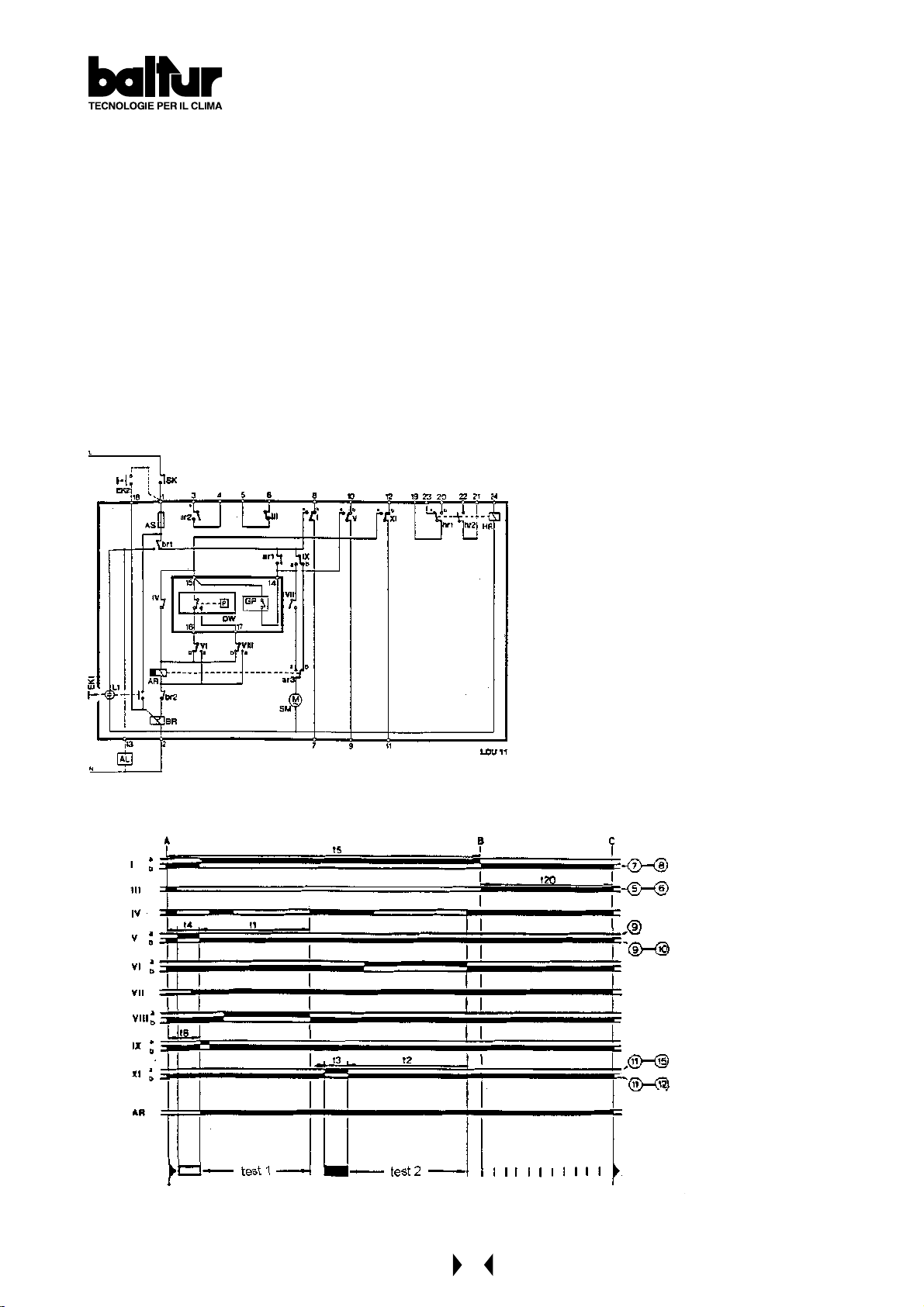
LDU 1 1.. GAS VALVE TIGHTNESS CONTROL EQUIPMENT
Control programme
t
5s Putting control circuit under atmospheric pressure
4
t
7,5s Time between start-up and energizing of main “AR” relay
6
t
22,5s 1st verification stage at atmospheric pressure
1
t
5s Putting control circuit gas under pressure
3
t
27,5s 2nd verification stage at gas pressure
2
t
67,5s Total time of tightness control, up to burner operation consent
5
t
22,5s Return of programmer to rest position = fresh verification is enabled
20
AL remote alarm signalling
AR main relay with “ar” contacts
AS equipment fuse
BR blocking relay with “ar” contacts
DW outer pressure switch (tightness control)
EK... unblocking button
GP outer pressure switch (for mains gas pressure)
HR auxiliary relay with “ar” contacts
L1 equipment trouble signalling lamp
SK line switch
I...XI programmer cam contacts
Course of
programme
Terminals activated by
equipment or by electric
connections
45
Page 46
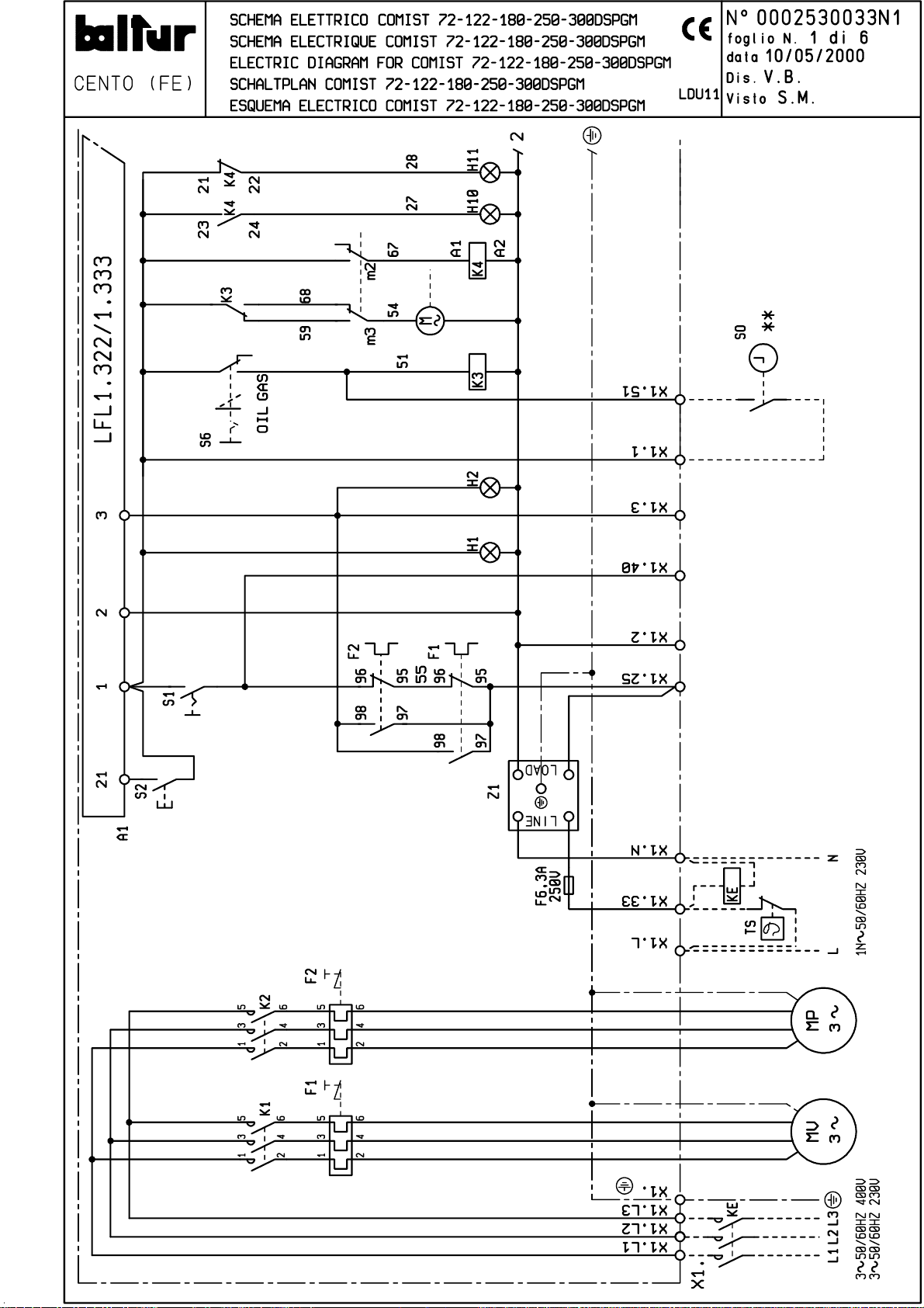
Page 47
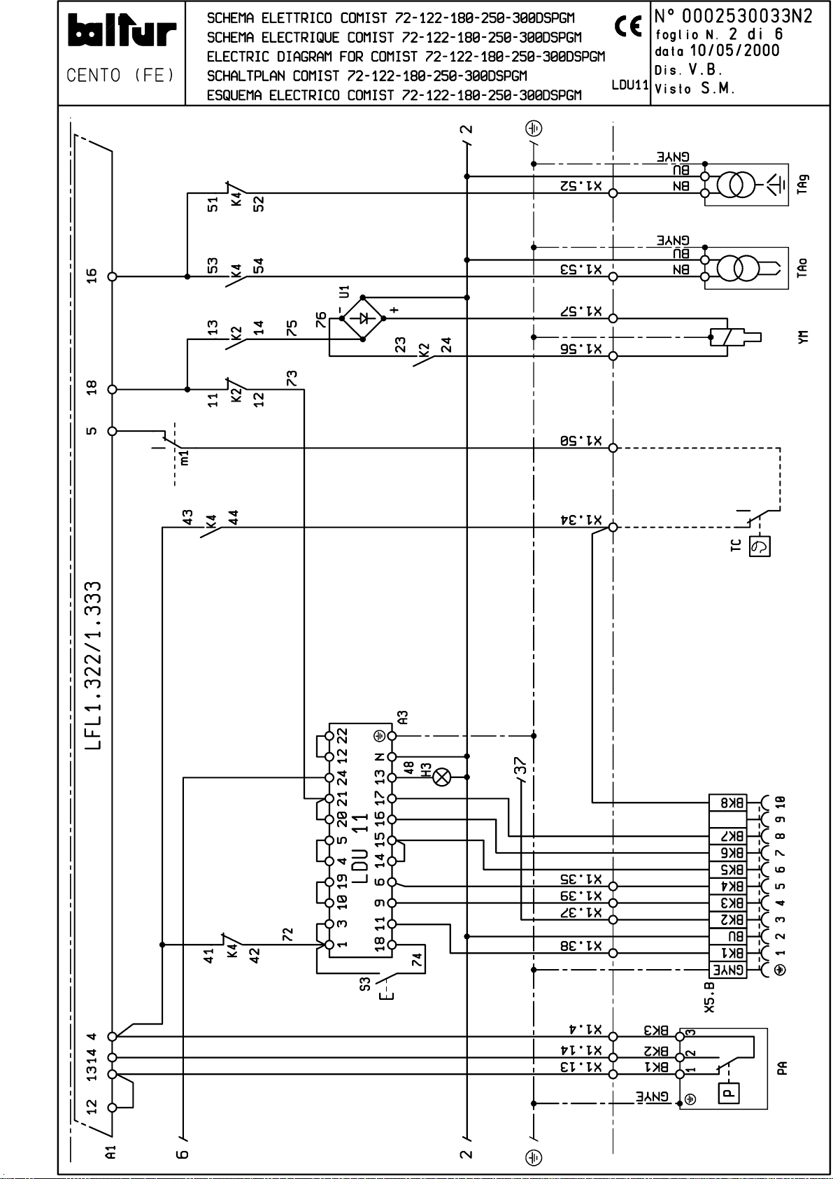
Page 48
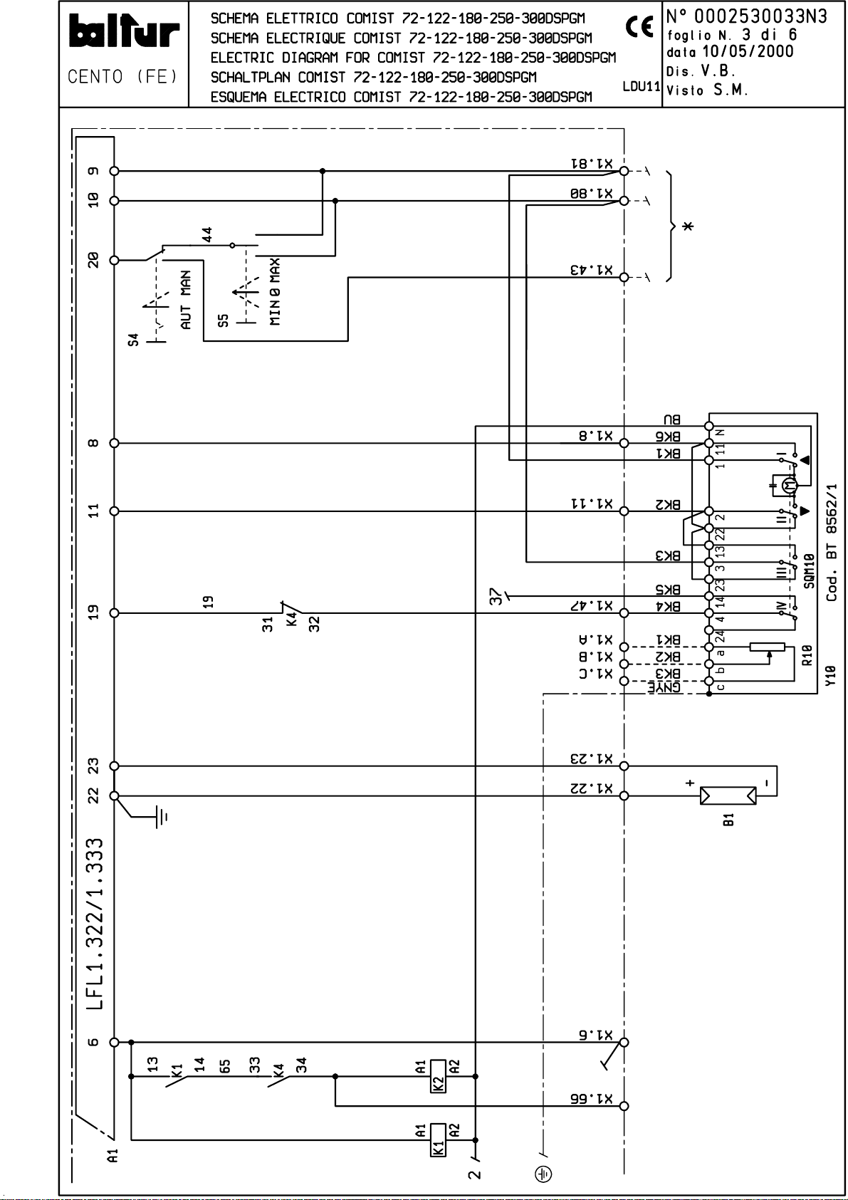
Page 49

Page 50
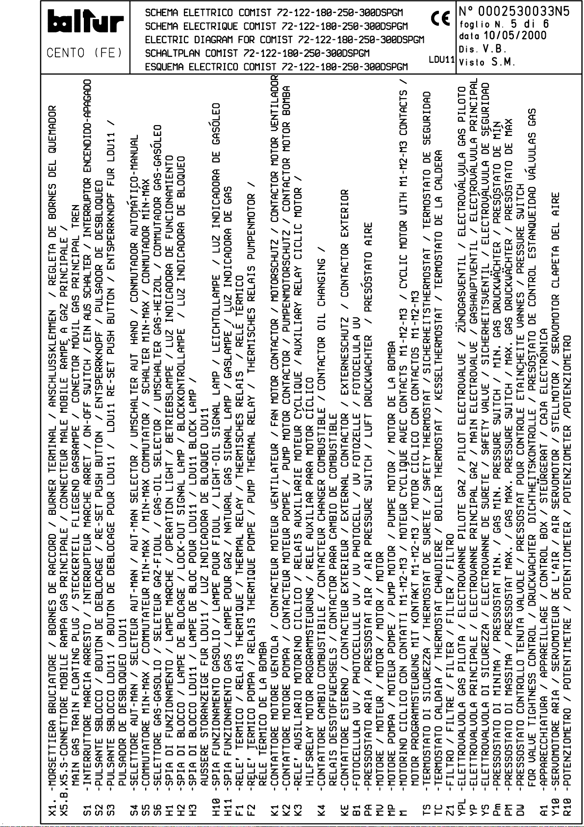
Page 51
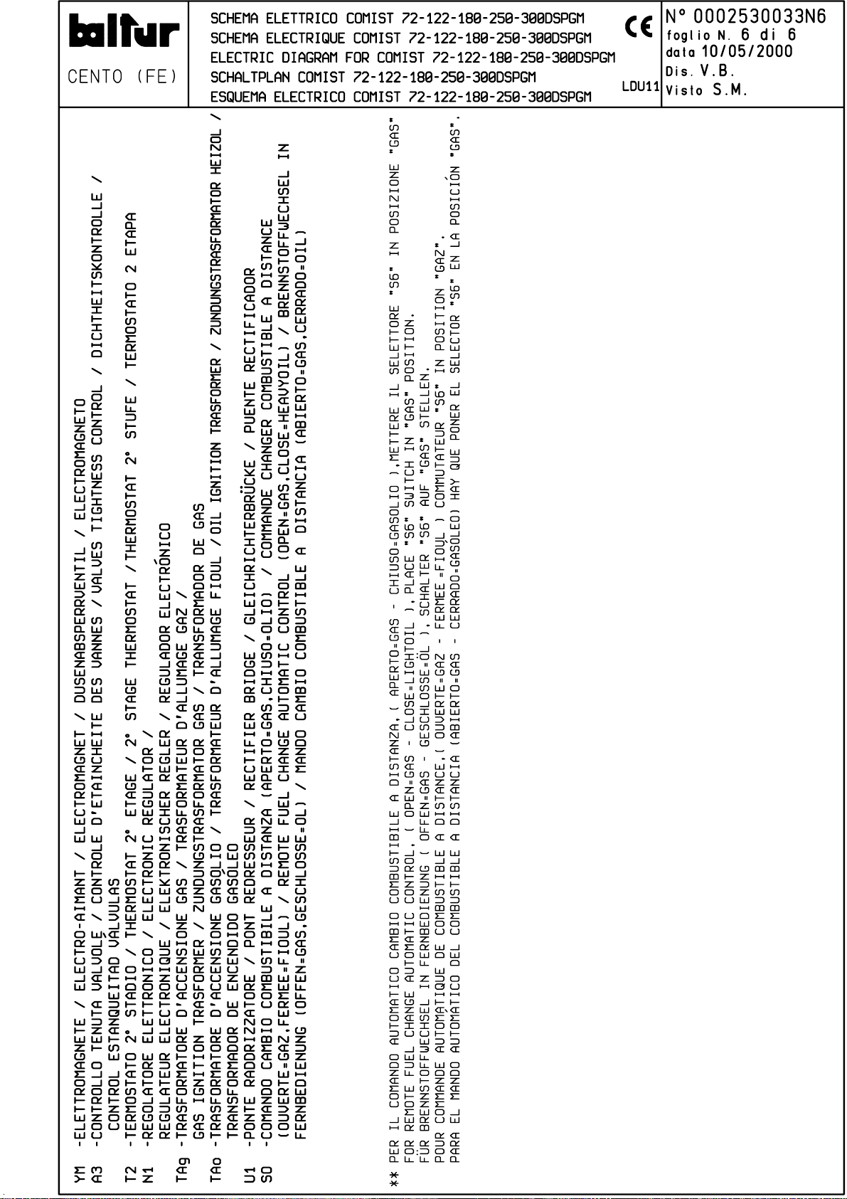
Page 52
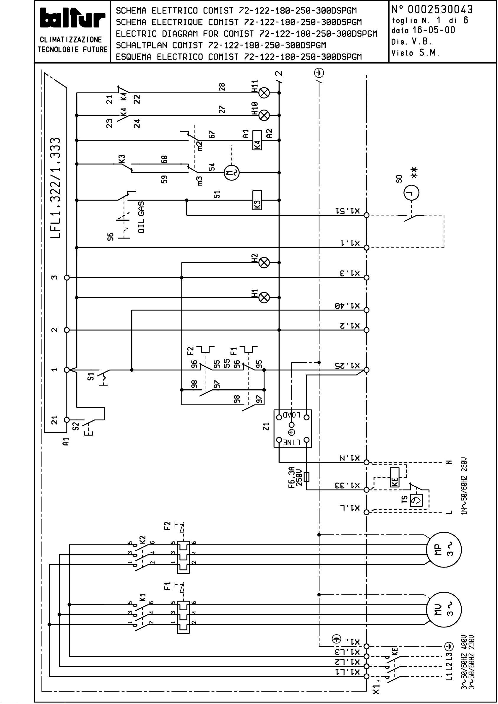
Page 53
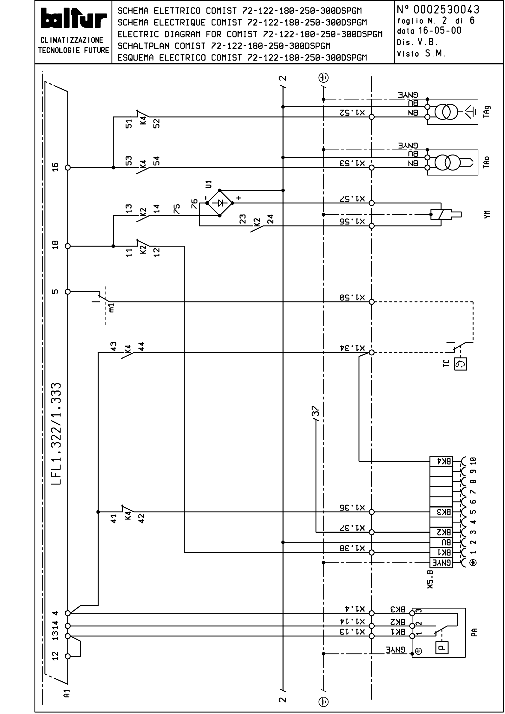
Page 54
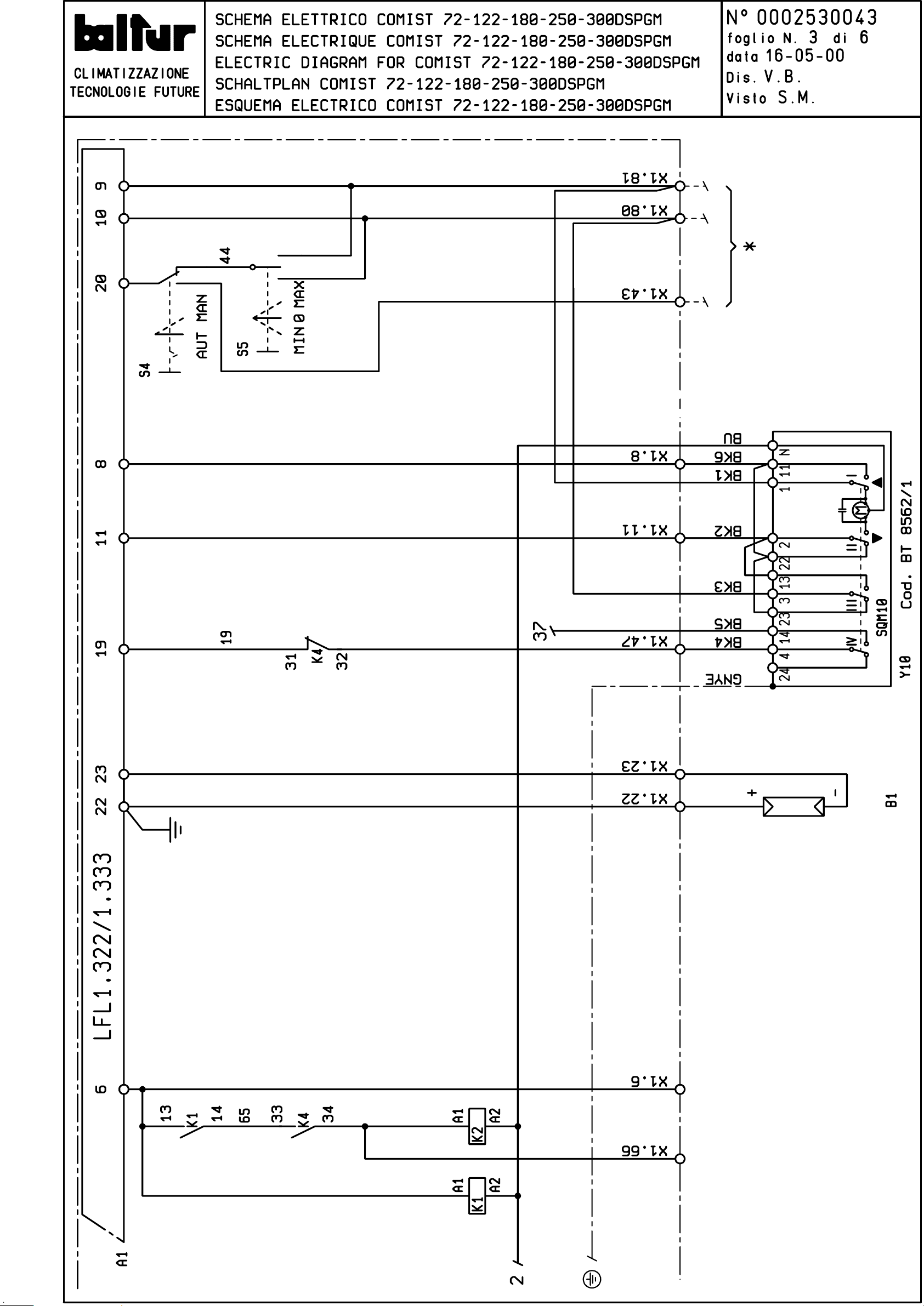
Page 55
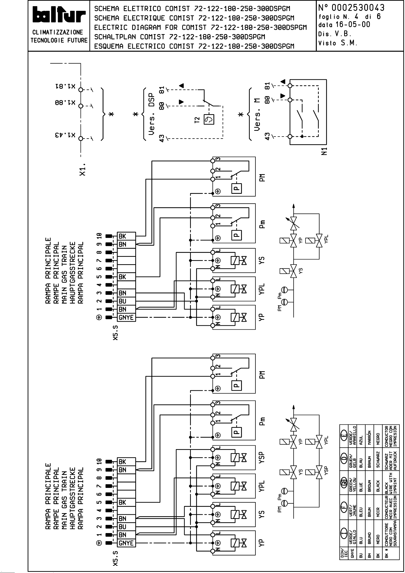
Page 56
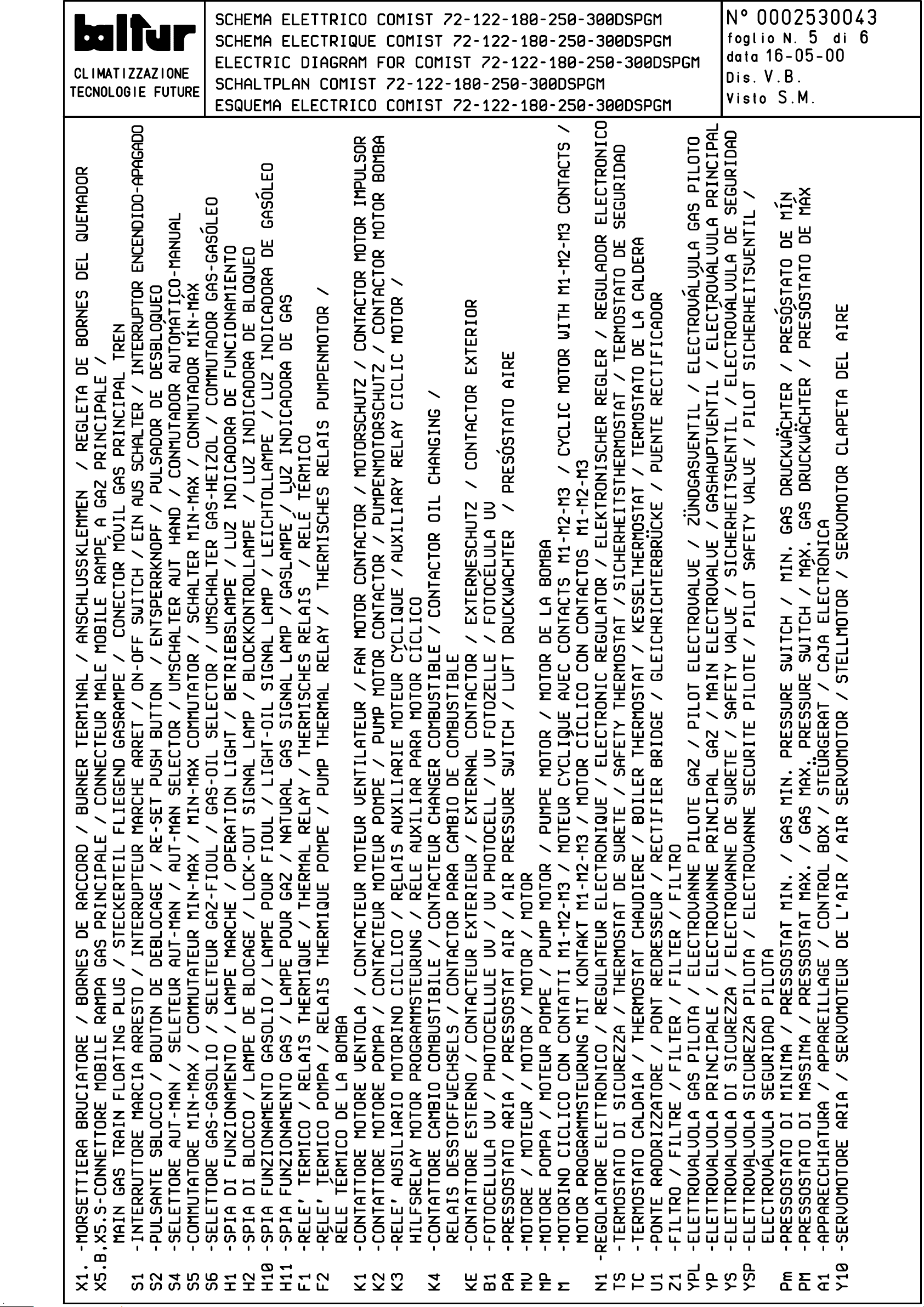
Page 57
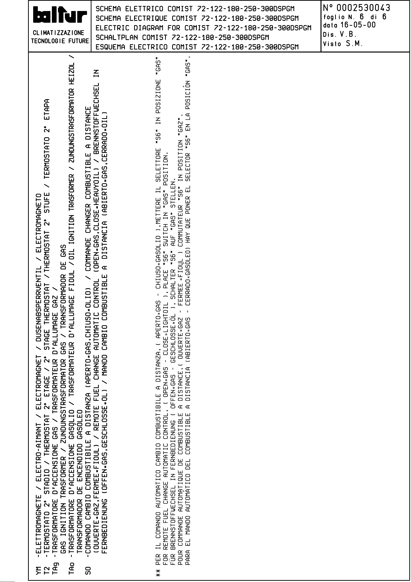
Page 58
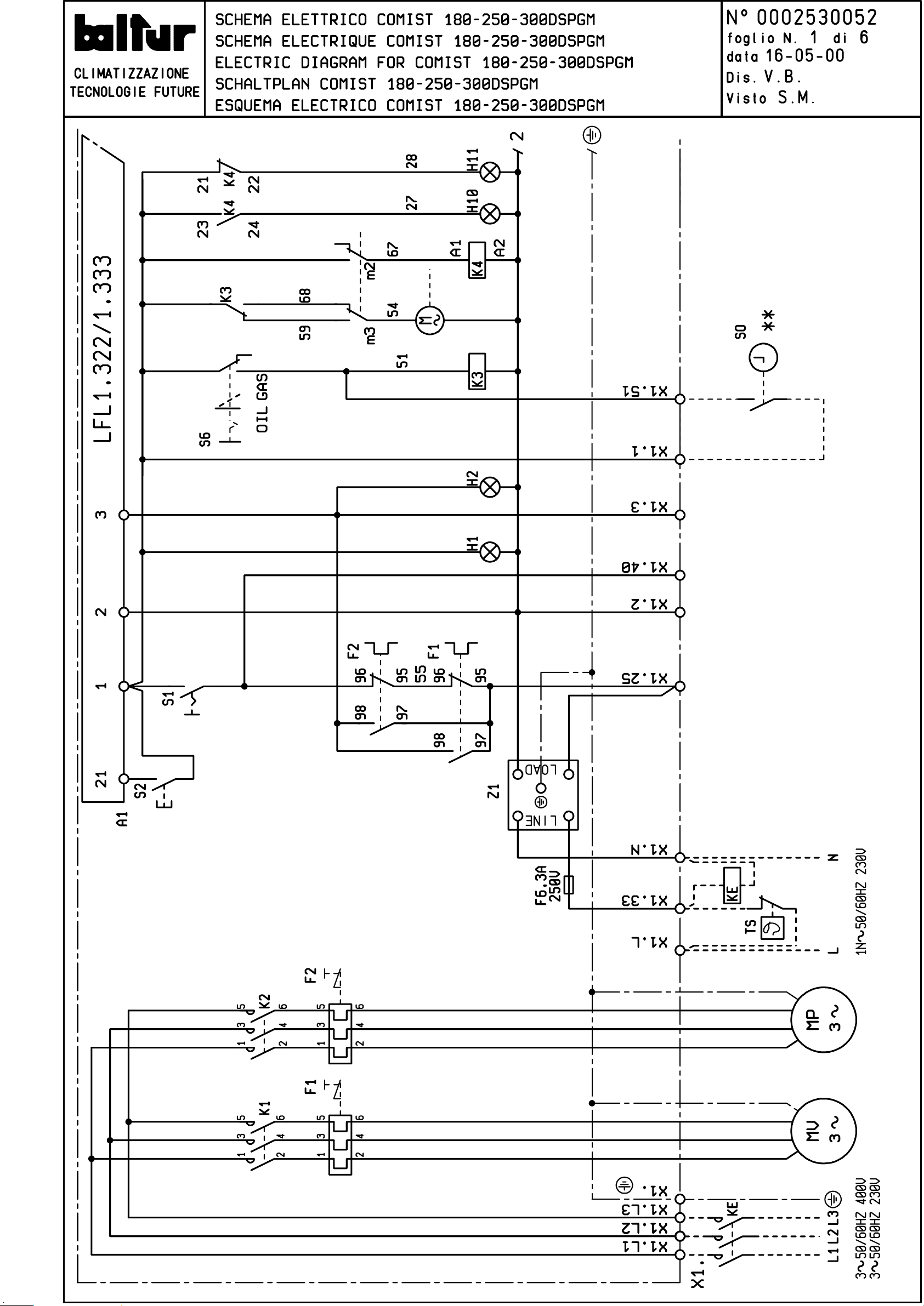
Page 59
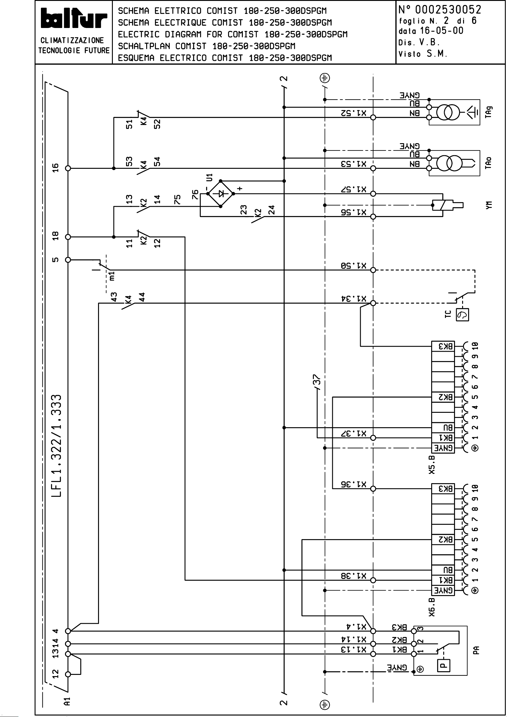
Page 60
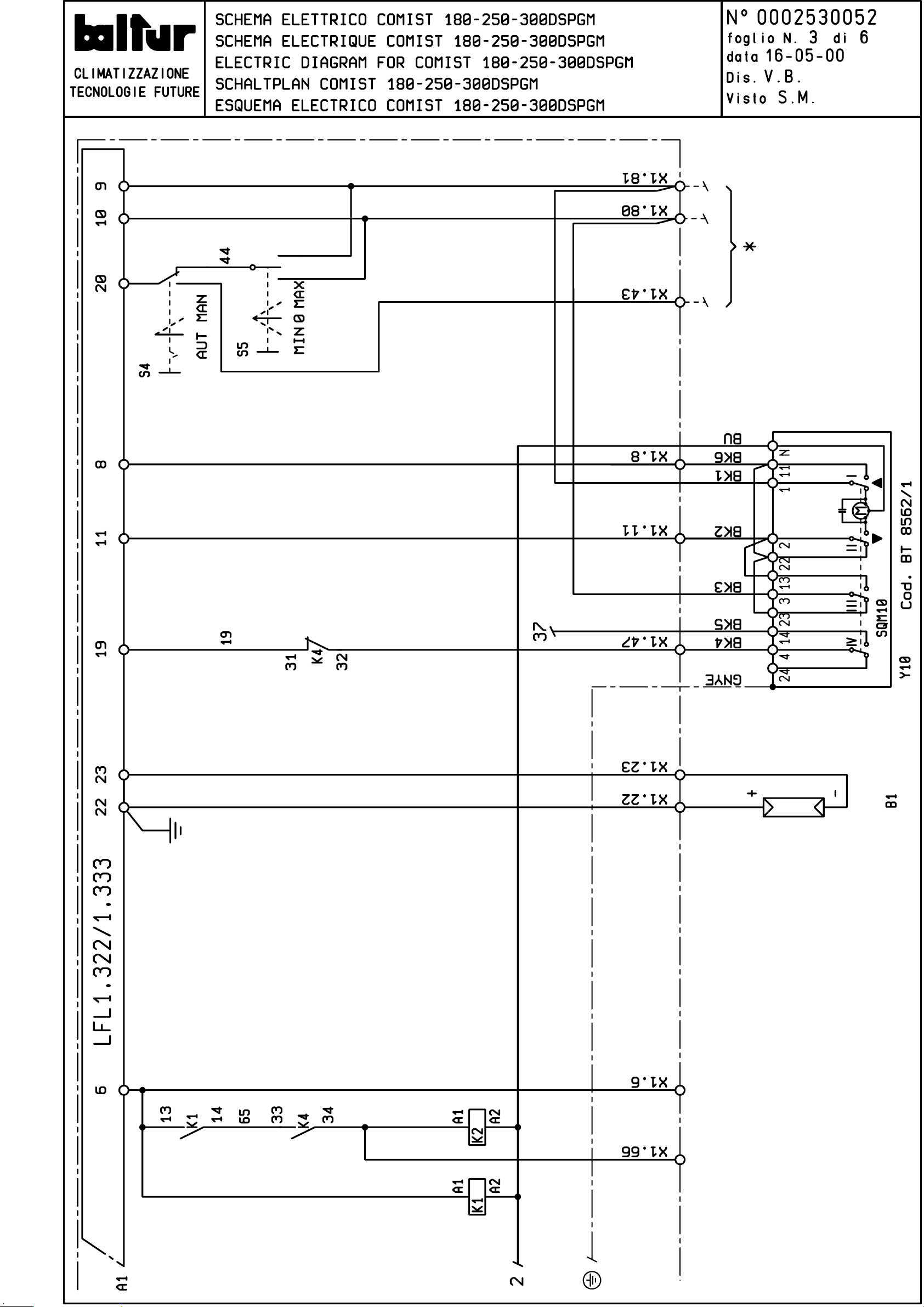
Page 61
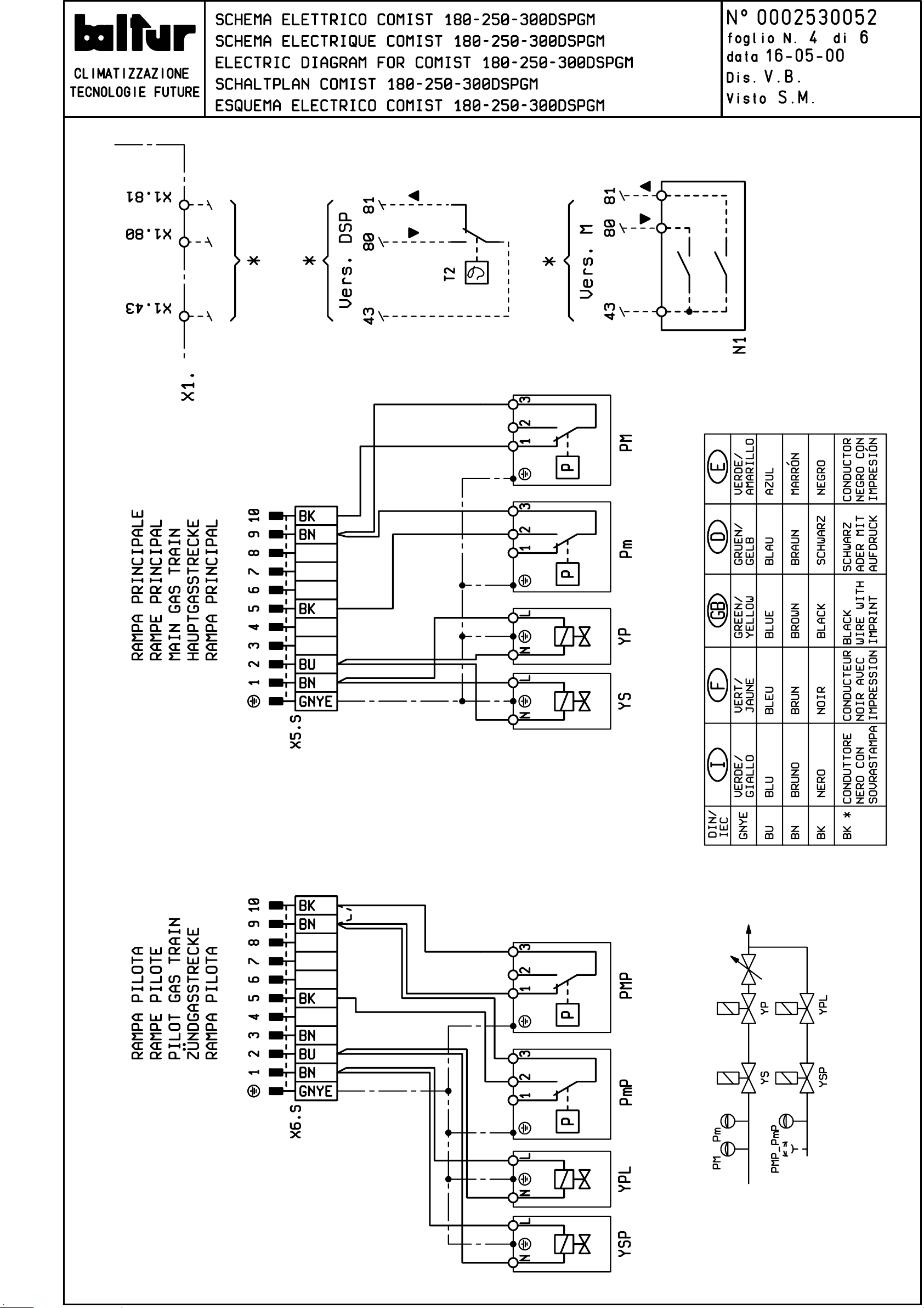
Page 62
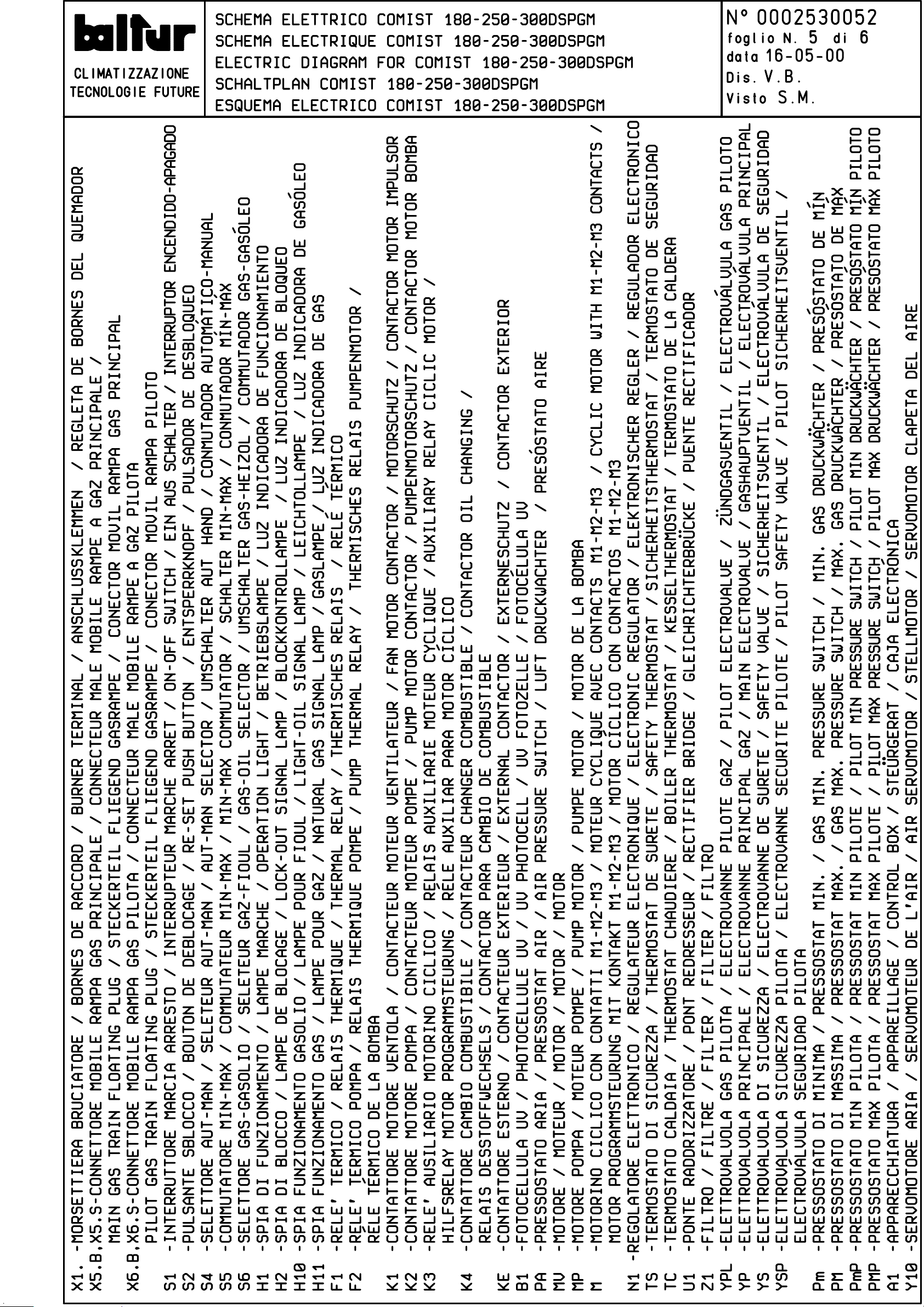
Page 63
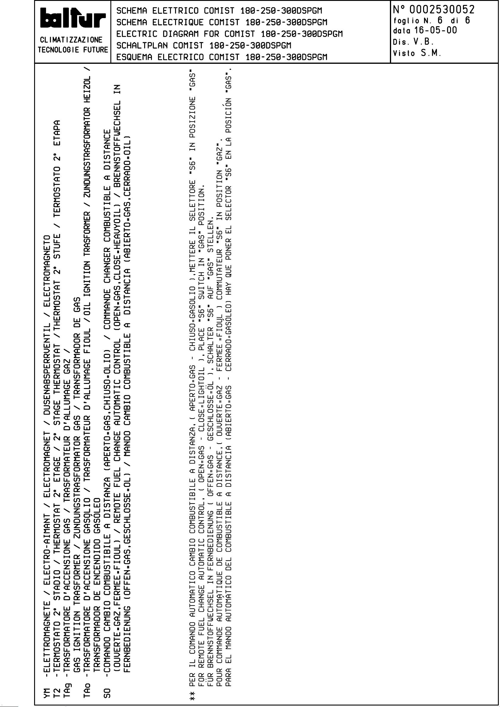
Page 64
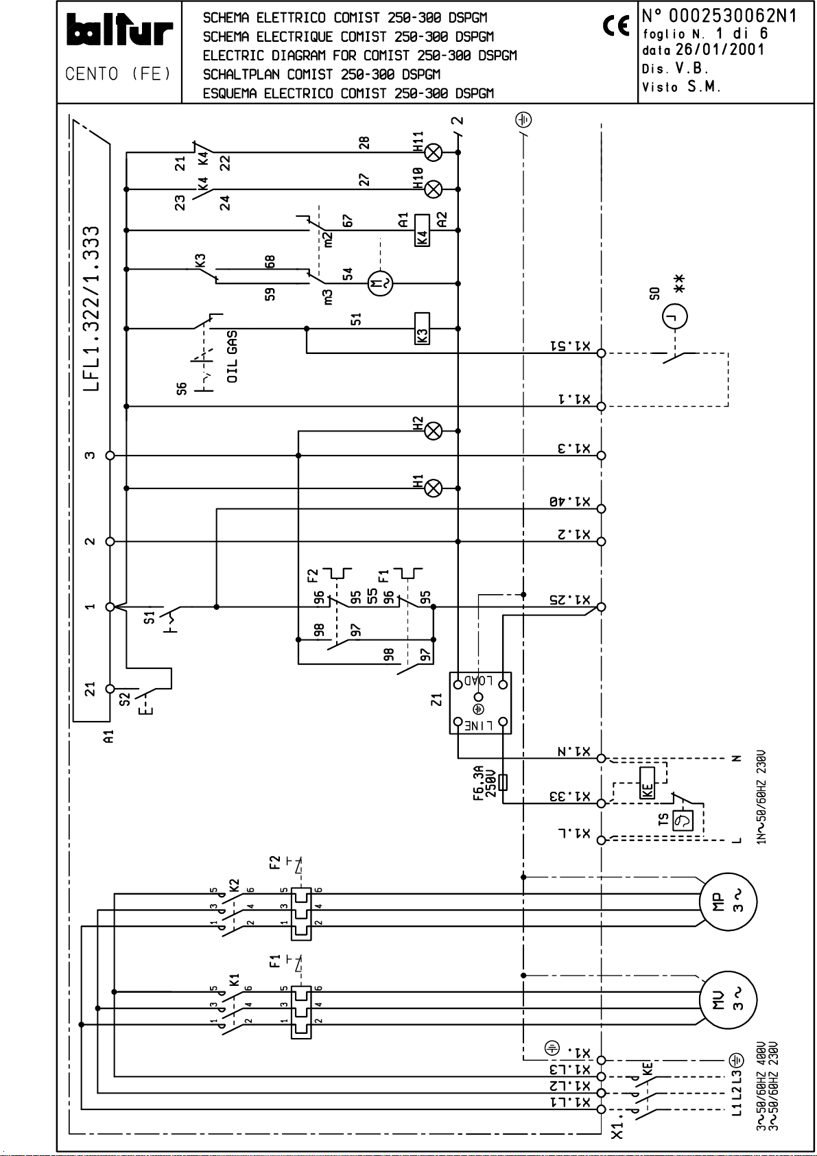
Page 65
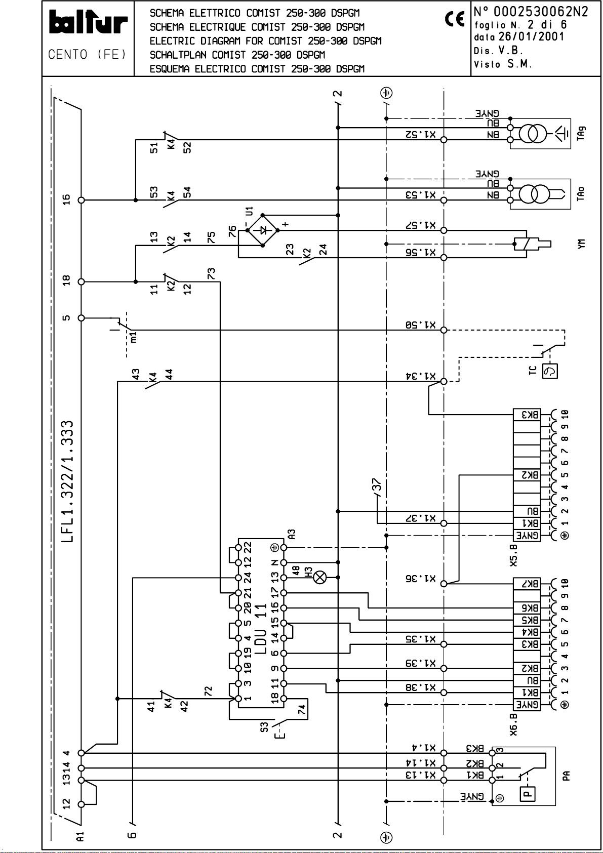
Page 66
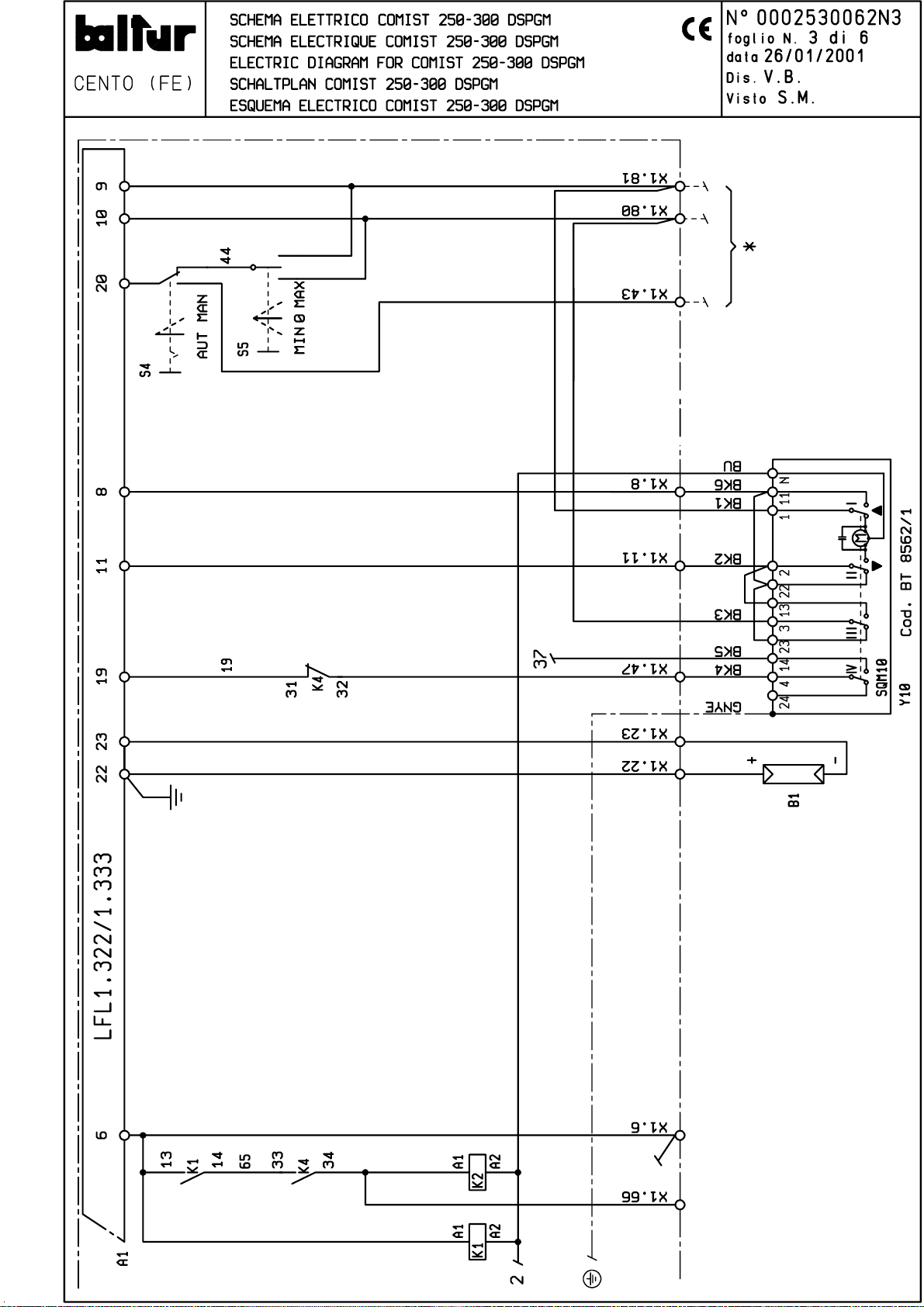
Page 67
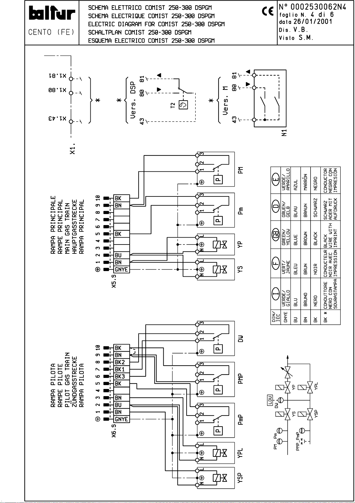
Page 68
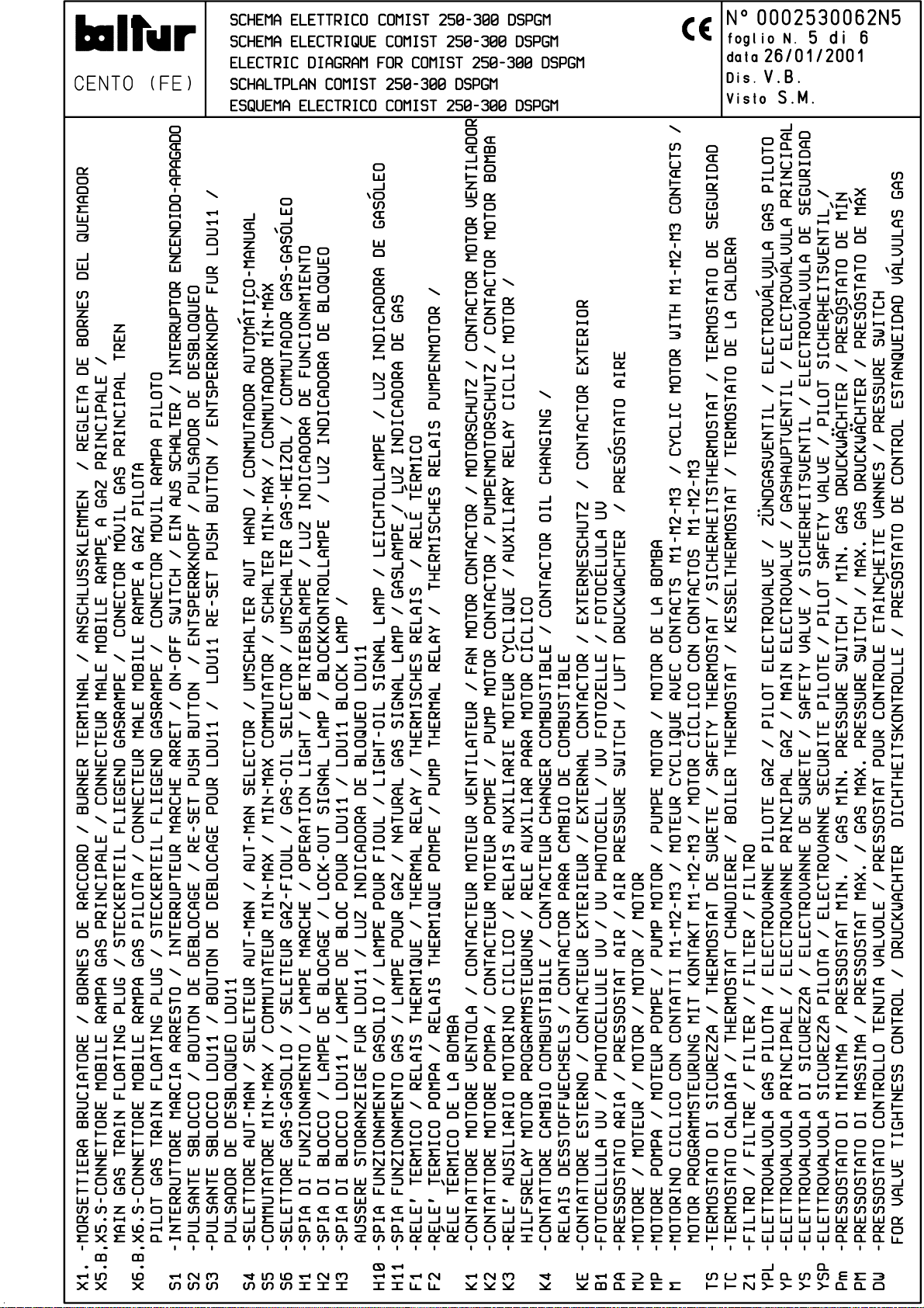
Page 69
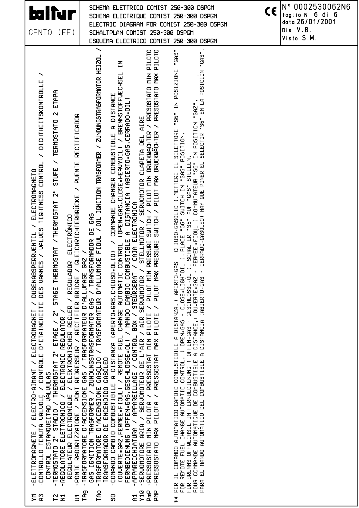
Page 70

BALTUR S.p.A.
Via Ferrarese 10 - 44042 CENTO (Ferrara) ITALIA
Tel. 051.684.37.11 Fax 051.685.75.27/28
(International Tel. ++39.051.684.37.11 - Fax ++39.051.683.06.86)
http://www.baltur.it - http://www.baltur.com
E-MAIL [email protected]
Technical data in this brochure are given as information only.
Baltur reserves the right to change specification, without notice.
 Loading...