

Page 1
BRUCIATORI DI GAS MONOSTADIO
SINGLE-STAGE GAS BURNERS
ITALIANO
Manuale istruzioni per l'installazione, l'uso
e la manutenzione
Instruction manual for
installation, use and maintenance
IT
EN
BTG 12
ISTRUZIONI ORIGINALI (IT)
ORIGINAL INSTRUCTIONS (IT)
0006160053_201912
Page 2

Page 3

ITALIANO
ITALIANO
SOMMARIO
Avvertenze per l'uso in condizioni di sicurezza ......................................................................................................................................................2
Caratteristiche tecniche ..........................................................................................................................................................................................5
Materiale a corredo ..........................................................................................................................................................................................6
Targa identicazione bruciatore........................................................................................................................................................................6
Dati registrazione prima accensione ................................................................................................................................................................6
Campo di lavoro ...............................................................................................................................................................................................7
Descrizione componenti ...................................................................................................................................................................................7
Dimensioni di ingombro ....................................................................................................................................................................................8
Collegamenti elettrici ..............................................................................................................................................................................................9
Descrizione del funzionamento ............................................................................................................................................................................10
Controllo tenuta valvole "VPS 504" (se presente) ..........................................................................................................................................10
Accensione e regolazione gas metano .................................................................................................................................................................11
Corrente ionizzazione.....................................................................................................................................................................................13
Regolazione aria sulla testa di combustione ..................................................................................................................................................13
Schema di regolazione testa di combustione e distanza disco elettrodi ........................................................................................................14
Apparecchiatura di comando e controllo TGRD 61 ..............................................................................................................................................15
Manutenzione .......................................................................................................................................................................................................21
tempi di manutenzione ...................................................................................................................................................................................22
Vita attesa ......................................................................................................................................................................................................23
Precisazioni sull'uso del propano .........................................................................................................................................................................24
Schema di principio per riduzione pressione G.P.L. a due stadi per bruciatore oppure caldaia ....................................................................25
Istruzioni per l'accertamento delle cause di irregolarità nel funzionamento e la loro eliminazione.......................................................................26
Schemi elettrici .....................................................................................................................................................................................................27
1 / 28
0006160053_201912
Page 4

ITALIANO
AVVERTENZE PER L'USO IN CONDIZIONI DI
SICUREZZA
SCOPO DEL MANUALE
Il manuale si propone di contribuire all'utilizzo sicuro del prodotto a
cui fa riferimento, mediante l'indicazione di quei comportamenti necessari prevedendo di evitare alterazioni delle caratteristiche di sicurezza derivanti da eventuali installazioni non corrette, usi erronei,
impropri o irragionevoli.
E’ esclusa qualsiasi responsabilità contrattuale ed extracontrattuale
del costruttore per i danni causati da errori nell’installazione e nell’uso, e comunque da inosservanza delle istruzioni date dal costruttore
stesso.
• Le macchine prodotte hanno una vita minima di 10 anni, se vengono rispettate le normali condizioni di lavoro ed effettuate le manu-
tenzioni periodiche indicate dal fabbricante.
• ll libretto di istruzioni costituisce parte integrante ed essenziale del
prodotto e dovrà essere consegnato all’utente.
• L'utente dovrà conservare con cura il libretto per ogni ulteriore con-
sultazione.
• Prima di iniziare a usare l’apparecchio, leggere attentamente
le “Istruzioni per l’uso” riportate nel manuale e quelle applica-
te direttamente sul prodotto, al ne di minimizzare i rischi ed
evitare incidenti.
• Prestare attenzione alle AVVERTENZE DI SICUREZZA, non adottare USI IMPROPRI.
• L'installatore deve valutare i RISCHI RESIDUI che potrebbero sus-
sistere.
• Per evidenziare alcune parti di testo o per indicare alcune speci-
che di rilevante importanza, sono stati adottati alcuni simboli di cui
viene descritto il signicato.
PERICOLO / ATTENZIONE
Il simbolo indica situazione di grave pericolo che, se trascurate,
possono mettere seriamente a rischio la salute e la sicurezza
delle persone.
CAUTELA / AVVERTENZE
Il simbolo indica che è necessario adottare comportamenti
adeguati per non mettere a rischio la salute e la sicurezza delle
persone e non provocare danni economici.
IMPORTANTE
Il simbolo indica informazioni tecniche ed operative di particolare importanza da non trascurare.
• L'apparecchio non è adatto a essere usato da persone (bambini
compresi) le cui capacità siche, sensoriali o mentali siano ridotte,
oppure con mancanza di esperienza o di conoscenza.
• l'uso dell'apparecchio è consentito a tali persone solo nel caso in
cui possano beneciare, attraverso l'intermediazione di una persona responsabile, di informazioni relative alla loro sicurezza, di una
sorveglianza, di istruzioni riguardanti l'uso dell'apparecchio.
• I bambini devono essere sorvegliati per sincerarsi che non giochino
con l'apparecchio.
• Questo apparecchio dovrà essere destinato solo all’uso per il quale
é stato espressamente previsto. Ogni altro uso é da considerarsi
improprio e quindi pericoloso.
• L’installazione dell’apparecchio deve essere effettuata in ottemperanza alle norme vigenti, secondo le istruzioni del costruttore a da
personale professionalmente qualicato.
• Per personale professionalmente qualicato si intende quello
avente specica e dimostrata competenza tecnica nel settore, in
accordo con la legislazione locale vigente.
• Un’errata installazione può causare danni a persone, animali o
cose, per i quali il costruttore non é responsabile.
• Dopo aver tolto ogni imballaggio assicurarsi dell’integrità del contenuto. In caso di dubbio non utilizzare l’apparecchio e rivolgersi al
fornitore. Gli elementi dell’imballaggio non devono essere lasciati
alla portata dei bambini in quanto potenziali fonti di pericolo.
• La maggior parte dei componenti dell'apparecchio e del suo im-
ballo è realizzata con materiali che possono essere riutilizzati.
L'imballaggio l'apparecchio ed i suoi componenti non possono essere smaltiti insieme ai normali riuti domestici, ma sono soggetti a
smaltimento conforme alle normative vigenti.
• Prima di effettuare qualsiasi operazione di pulizia o manutenzione,
disinserire l’apparecchio dalla rete di alimentazione agendo sull’interruttore dell’impianto e/o attraverso gli appositi organi di intercettazione.
• Se l’apparecchio dovesse essere venduto o trasferito ad un altro
proprietario o se si dovesse traslocare e lasciare l’apparecchio, as-
sicurarsi sempre che il libretto accompagni l’apparecchio in modo
che possa essere consultato dal nuovo proprietario e/o dall’installatore.
• Con apparecchio in funzione non toccare le parti calde normal-
mente situate in vicinanza della amma e dell’eventuale sistema di
preriscaldamento del combustibile. Possono rimanere calde anche
dopo un arresto non prolungato dell'apparecchio.
CONDIZIONI E DURATA DELLO STOCCAGGIO
Gli apparecchi vengono spediti con l'imballaggio del costruttore e trasportati su gomma, via mare e via ferrovia in conformità con le norme
per il trasporto di merci in vigore per l'effettivo mezzo di trasporto
utilizzato.
Per apparecchi non utilizzati, è necessario conservarli in locali chiusi
con la dovuta circolazione d'aria a condizioni standard con temperatura compresa fra -25° C e + 55° C.
Il periodo di stoccaggio è di 3 anni.
AVVERTENZE GENERALI
• La data di produzione dell'apparecchio (mese, anno) sono indicati
sulla targa identicazione bruciatore presente sull'apparecchio.
0006160053_201912
2 / 28
Page 5

ITALIANO
• In caso di guasto e/o di cattivo funzionamento dell’apparecchio,
disattivarlo, astenendosi da qualsiasi tentativo di riparazione o di
intervento diretto. Rivolgersi esclusivamente a personale profes-
sionalmente qualicato.
• L’eventuale riparazione dei prodotti dovrà essere effettuata solamente da un centro di assistenza autorizzato da BALTUR o dal suo
distributore locale, utilizzando esclusivamente ricambi originali.
• Il costruttore e/o il suo distributore locale declinano qualunque responsabilità per incidenti o danni causati da modiche non autoriz-
zate sul prodotto o dalla inosservanza delle prescrizioni contenute
nel manuale.
AVVERTENZE DI SICUREZZA PER L’INSTALLAZIONE
• L'apparecchio deve essere installato in un locale idoneo con una
adeguata ventilazione secondo le leggi e norme vigenti.
• La sezione delle griglie di aspirazione dell’aria e le aperture di
aerazione del locale di installazione non devono essere ostruite
o ridotte.
• Il locale di installazione NON deve presentare il rischio di esplosione e/o incendio.
• Prima dell’installazione si consiglia di effettuare una accurata pu-
lizia interna di tutte le tubazioni dell’impianto di alimentazione del
combustibile.
• Prima di collegare l'apparecchio accertarsi che i dati di targa siano
corrispondenti a quelli della rete di alimentazione (elettrica, gas,
gasolio o altro combustibile).
• Accertarsi che il bruciatore sia ssato saldamente al generatore di
calore secondo le indicazioni del costruttore.
• Effettuare gli allacciamenti alle fonti di energia a regola d’arte come
indicato negli schemi esplicativi secondo i requisiti normativi e legislativi in vigore al momento dell’installazione.
• Vericare che l’impianto di smaltimento fumi NON sia ostruito.
• Se si decide di non utilizzare, in via denitiva il bruciatore, si do-
vranno far effettuare da personale professionalmente qualicato le
seguenti operazioni:
- Disinserire l’alimentazione elettrica staccando il cavo di alimentazione dell’interruttore generale.
- Chiudere l’alimentazione del combustibile attraverso la valvola
manuale di intercettazione e asportare i volantini di comando
dalla loro sede.
- Rendere innocue quelle parti che potrebbero essere potenziali
fonti di pericolo.
• L’impianto di alimentazione del combustibile sia dimensionato per
la portata necessaria al bruciatore e che sia dotato di tutti i dispositivi di sicurezza e controllo prescritti dalle norme vigenti.
• Prima di avviare il bruciatore e almeno una volta all’anno, far ef-
fettuare da personale professionalmente qualicato le seguenti
operazioni:
- Tarare la portata di combustibile del bruciatore secondo la
potenza richiesta dal generatore di calore.
- Eseguire il controllo della combustione regolando la portata
d’aria comburente e/o del combustibile, per ottimizzare il
rendimento di combustione e le emissioni in osservanza alla
legislazione vigente.
- Vericare la funzionalità dei dispositivi di regolazione e di
sicurezza.
- Vericare la corretta funzionalità del condotto di evacuazione
dei prodotti della combustione.
- Controllare la tenuta nel tratto interno ed esterno dei tubi di
alimentazione del combustibile.
- Controllare al termine delle regolazioni che tutti i sistemi di
bloccaggio meccanico dei dispositivi di regolazione siano ben
serrati.
- Accertarsi che siano disponibili le istruzioni relative all’uso e
manutenzione del bruciatore.
• In caso di ripetuti arresti in blocco del bruciatore non insistere con
le procedure di riarmo manuale, ma rivolgersi a personale profes-
sionalmente qualicato.
• Allorché si decida di non utilizzare il bruciatore per un certo periodo,
chiudere il rubinetto o i rubinetti di alimentazione del combustibile.
AVVERTENZE PER L'AVVIAMENTO IL COLLAUDO L'USO E LA
MANUTENZIONE
• L'avviamento, il collaudo e la manutenzione devono essere effet-
tuati esclusivamente da personale professionalmente qualicato,
in ottemperanza alle disposizioni vigenti.
• Fissato il bruciatore al generatore di calore, accertarsi durante il
collaudo che la amma generata non fuoriesca da eventuali fessure.
• Controllare la tenuta dei tubi di alimentazione del combustibile
all'apparecchio.
• Vericare che la portata del combustibile coincida con la potenza
richiesta al bruciatore.
• Tarare la portata di combustibile del bruciatore secondo la potenza
richiesta dal generatore di calore.
• La pressione di alimentazione del combustibile deve essere com-
presa nei valori riportati nella targhetta presente sul bruciatore e/o
sul manuale
0006160053_201912
3 / 28
Page 6

ITALIANO
Avvertenze particolari per l’uso del gas.
• Vericare che la linea di adduzione e la rampa siano conformi alle
norme e prescrizioni vigenti.
• Vericare che tutte le connessioni gas siano a tenuta.
• Non lasciare l’apparecchio inutilmente inserito quando non è utiliz-
zato e chiudere sempre il rubinetto del gas.
• In caso di assenza prolungata dell’utente dell’apparecchio chiude-
re il rubinetto principale di adduzione del gas al bruciatore.
• Avvertendo odore di gas:
- non azionare interruttori elettrici, il telefono e qualsiasi altro
oggetto che possa provocare scintille;
- aprire immediatamente porte e nestre per creare una corrente
d’aria che purichi il locale;
- chiudere i rubinetti del gas;
- richiedere l’intervento di personale professionalmente qualicato.
• Non ostruire le aperture di aerazione del locale dove é installato un
apparecchio a gas, per evitare situazioni pericolose quali la formazione di miscele tossiche ed esplosive.
RISCHI RESIDUI
• Nonostante l'accurata progettazione del prodotto, nel rispetto delle
norme cogenti e delle buone regole nell'impiego corretto possono
permanere dei rischi residui. Questi vengono segnalati sul brucia-
tore con opportuni Pittogrammi.
- Allorché si decida di non utilizzare l’apparecchio per un certo
periodo é opportuno spegnere l’interruttore elettrico di alimentazione a tutti i componenti dell’impianto che utilizzano energia
elettrica (pompe, bruciatore, ecc.).
• Usare cavi essibili secondo norma EN60335-1:EN 60204-1
- se sotto guaina di PVC almeno tipo H05VV-F;
- se sotto guaina di gomma almeno tipo H05RR-F; LiYCY
450/750V
- senza nessuna guaina almeno tipo FG7 o FROR, FG70H2R
• L’equipaggiamento elettrico funziona correttamente quando l’umidità relativa non supera il 50% a una temperatura massima di +40°
C. Umidità relative superiori sono ammesse a temperature inferiori(esempio 90% a 20° C).
• L’equipaggiamento elettrico funziona correttamente ad altitudini
no a 1000 m sopra il livello del mare.
DICHIARAZIONE DI CONFORMITÀ
IMPORTANTE
Dichiariamo che i nostri bruciatori ad aria sofata di combustibili gassosi, liquidi e misti, rispettano i requisiti essenziali impo-
sti dalle Direttive e Regolamenti europei e sono conformi alle
Norme europee
Una copia della dichiarazione di conformità CE è fornita a corredo con il bruciatore.
ATTENZIONE
Organi meccanici in movimento.
ATTENZIONE
Materiali a temperature elevate.
ATTENZIONE
Quadro elettrico sotto tensione.
AVVERTENZE SICUREZZA ELETTRICA
• Vericare che l’apparecchio abbia un idoneo impianto di messa a
terra, eseguito secondo le vigenti norme di sicurezza.
• Far vericare da personale professionalmente qualicato che
l’impianto elettrico sia adeguato alla potenza massima assorbita
dall’apparecchio indicata in targa.
• Prevedere un interruttore onnipolare con distanza d’apertura dei
contatti uguale o superiore a 3 mm per l’allacciamento alla rete
elettrica, come previsto dalle normative di sicurezza vigenti (condizione della categoria di sovratensione III).
• Sguainare l’isolante esterno del cavo di alimentazione nella misura
strettamente necessaria al collegamento, evitando così che il lo
possa venire a contatto con parti metalliche.
• L’uso di un qualsiasi componente che utilizza energia elettrica
comporta l’osservanza di alcune regole fondamentali quali:
- non toccare l’apparecchio con parti del corpo bagnate o umide
e/o a piedi umidi;
- non tirare i cavi elettrici;
- non lasciare esposto l’apparecchio ad agenti atmosferici (pioggia, sole, ecc.) a meno che non sia espressamente previsto;
- non permettere che l’apparecchio sia usato da bambini o da
persone inesperte;
- ll cavo di alimentazione dell’apparecchio non deve essere sostituito dall’utente. In caso di danneggiamento del cavo, spegnere
l’apparecchio. Per la sua sostituzione,rivolgersi esclusivamente
a personale professionalmente qualicato;
4 / 28
0006160053_201912
Page 7

CARATTERISTICHE TECNICHE
MODELLO BTG 12
PIN omologazione CE0085BQ0476
Potenza termica massima metano
Potenza termica minima metano
¹) emissioni metano
Funzionamento
Trasformatore metano 50 hz
Portata termica massima metano
Portata termica minima metano
Pressione massima metano
Pressione minima metano
Potenza termica massima propano
Potenza termica minima propano
Portata termica massima propano
Portata termica minima propano
Pressione massima propano
Pressione minima propano
²)emissioni propano
Motore ventola 50hz
Giri motore ventola 50hz
Potenza elettrica assorbita* 50hz
Tensione di alimentazione 50 hz
Grado di protezione
Rilevazione amma
Apparecchiatura
Temperatura aria ambiente di funzionamento
Pressione sonora**
Peso con imballo
Peso senza imballo
kW
kW
mg/kWh
Stm³/h
Stm³/h
hPa (mbar)
hPa (mbar)
kW
kW
Stm³/h
Stm³/h
hPa (mbar)
hPa (mbar)
mg/kWh
kW
giri/min.
kW
°C
dBA
kg
kg
SONDA IONIZZAZIONE
BRAHMA KOMPACT TGRD61
115
35
Classe 2
monostadio
17 kV - 60 mA
11.88
3.6
360
16.6
115
35
4.7
1.43
200
14.6
Classe 3
0.11
2800
0.2
1N~ 230V ± 10%
IP 20
-15 ÷ +40
60
12
10.75
ITALIANO
Potere calorico inferiore alle condizioni di riferimento 15° C, 1013 hPa (mbar):
Gas metano: Hi = 9,45 kWh/Stm³ = 34,02 MJ/Stm³
Propano: Hi = 24,44 kWh/Stm³ = 88,00 MJ/Stm³
Per tipi di gas e pressioni diverse, consultare i nostri ufci commerciali.
* Assorbimento totale, in fase di partenza, con trasformatore d'accensione inserito.
Le misure sono state effettuate in conformità alla norma EN 15036 - 1.
** La pressione sonora e stata rilevata con bruciatore funzionante alla portata termica nominale massima, alle condizioni ambientali nel labora-
torio del costruttore e non è confrontabile con misure effettuate in siti diversi.
Emissioni CO metano / propano ≤ 100 mg/kWh
¹) EMISSIONI GAS METANO
Classi denite secondo la normativa EN 676.
Classe
1 ≤ 170
2 ≤ 120
3 ≤ 80
Emissioni NOx in mg/kWh gas
metano
²) EMISSIONI GAS PROPANO
Classi denite secondo la normativa EN 676.
Classe
1 ≤ 230
2 ≤ 180
3 ≤ 140
Emissioni NOx in mg/kWh gas
propano
5 / 28
0006160053_201912
Page 8
Targa_descr_bru
ITALIANO
MATERIALE A CORREDO
MODELLO BTG 12
Flangia attacco bruciatore 1
Guarnizione angia attacco bruciatore 1
Prigionieri N°4 M8 x 37
Dadi esagonali N°5 M8
Rondelle piane N°4 Ø 8
Vite N°1 M8 x 25
Connettore 7 poli 1
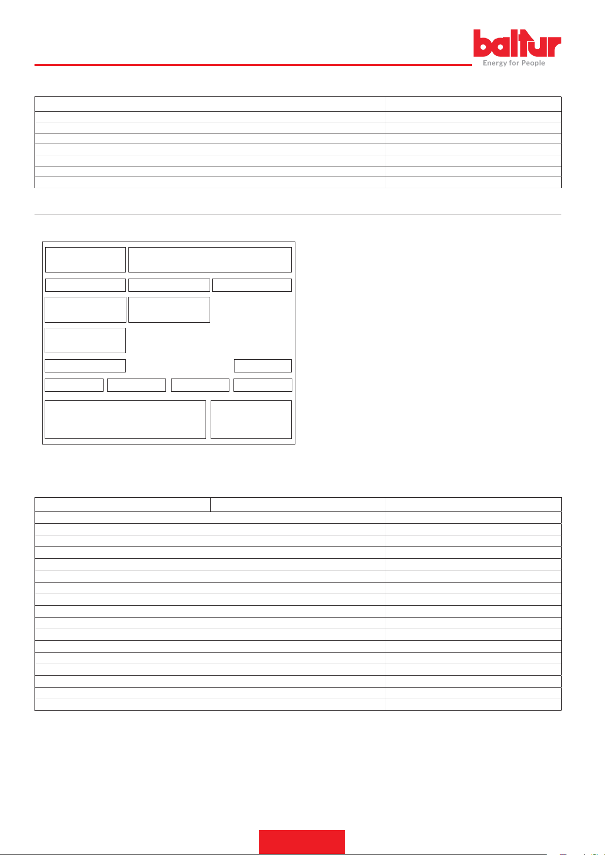
TARGA IDENTIFICAZIONE BRUCIATORE
1 Logo aziendale
2 Ragione sociale azienda
1 2
3 4 5
6 7
8
9
10 13
11
12
14
1615
3 Codice prodotto
4 Modello bruciatore
5 Matricola
6 Potenza combustibili liquidi
7 Potenza combustibili gassosi
8 Pressione combustibili gassosi
9 Viscosità combustibili liquidi
10 Potenza motore ventilatore
11 Tensione di alimentazione
12 Grado di protezione
13 Paese di costruzione e numeri di certicato di omologazione
14 Data di produzione mese / anno
15 -
16 Codice a barre matricola bruciatore
DATI REGISTRAZIONE PRIMA ACCENSIONE
Modello: Data: ora:
Tipo di gas
Indice di Wobbe inferiore
Potere calorico inferiore
Portata min gas
Portata max gas
Potenza min gas
potenza max gas
Pressione gas di rete
Pressione gas a valle dello stabilizzatore
CO (alla potenza minima)
CO2 (alla potenza minima)
Nox (alla potenza minima)
CO (alla potenza massima)
CO2 (alla potenza massima)
Nox (alla potenza massima)
temperatura fumi
temperatura aria
hPa (mbar)
hPa (mbar)
Stm³/h
Stm³/h
kW
kW
ppm
%
ppm
ppm
%
ppm
6 / 28
0006160053_201912
Page 9
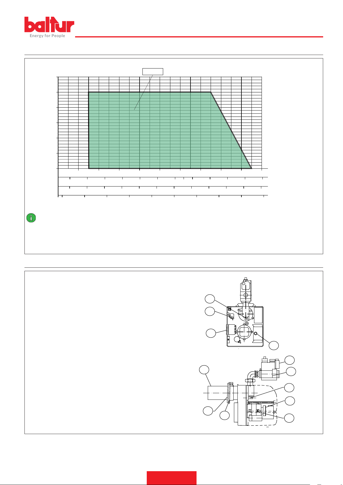
CAMPO DI LAVORO
1,5
2
2,5
3
3,5
4
4,5
1
5
5.5
ITALIANO
2.5
1.5
0.5
mbar
3
2
1
0
30 40 50
30
40 50 60 70 80 90
3
4 5 6 7 8 9 10 11
BTG 12
60 70 80 90
100 110
100
110
120
12 13 14
130
0002922950
kcal/hx1.000
120
kW
140
mn³/h(metano)
mn³/h(G.P.L)
IMPORTANTE
I campi di lavoro sono ottenuti su caldaie di prova rispondenti alla norma EN676 e sono orientativi per gli accoppiamenti bruciatore-caldaia. Per il corretto funzionamento del bruciatore le dimensioni della camera di combustione devono essere rispondenti alla normativa
vigente; in caso contrario vanno consultati i costruttori.
Il bruciatore non deve operare al di fuori del campo di lavoro dato.
DESCRIZIONE COMPONENTI
1 Riferimento disposizione disco - testa
2 Vite di regolazione apertura serranda aria
3 Connettore 7 poli
4 Apparecchiatura
5 Testa di combustione
6 Guarnizione isolante
7 Flangia attacco bruciatore
8 Motore
9 Pressostato aria
10 Vite regolazione disco testa
11 Valvola gas monoblocco
12 Pressostato di minima pressione gas
0002471470nom
1
2
3
4
12
5
11
10
9
6
7
8
7 / 28
0006160053_201912
Page 10
ITALIANO
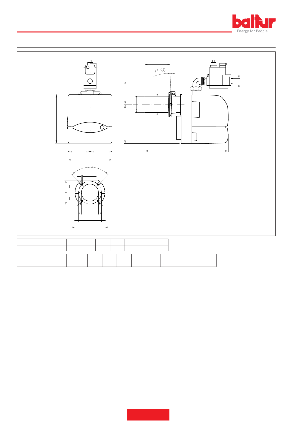
DIMENSIONI DI INGOMBRO
D
B6
EØ
B
B1
A1
45°
I1
A2
A
45°
M
N
L
I
FØ
C
G
0002471470dim
Modello A A1 B B1 B2 B6 C
BTG 12 246 123 289 219 70 53 450
Modello D E Ø F Ø G I I1 LØ M N Ø
BTG 12 70 ÷ 150 90 90 Rp 3/4 170 140 130 ÷ 155 M8 95
8 / 28
0006160053_201912
Page 11

COLLEGAMENTI ELETTRICI
• Rispettare le normative nazionali ed europee applicabili (es. EN
60335-1/EN 50165) relative alla sicurezza elettrica;
• Connettere i dispositivi, senza opzione N o N1, all’alimentazione
elettrica rispettando la polarità fase-neutro della rete.
• Le versioni a gas, con elettrodo di rilevazione, sono provviste di un
dispositivo di riconoscimento della polarità.
• Il mancato rispetto della polarità fase-neutro provoca un arresto
di blocco non volatile alla ne del tempo di sicurezza; In caso di
cortocircuito "parziale" o un insufciente isolamento tra linea e terra, la tensione sull'elettrodo di rivelazione può essere ridotta no a
provocare l'arresto di blocco dell'apparecchio, a causa dell'impossibilità di rivelare il segnale di amma.
• Prima della messa in funzione controllare bene i cavi.
• Cablaggi errati possono danneggiare l'apparecchio e compromettere la sicurezza dell'impianto;
• Assicurare un ottimo collegamento fra il morsetto di terra dell'appa-
recchio, la carcassa metallica del bruciatore e la terra dell'impianto
elettrico;
• Evitare di posare il cavo di rivelazione assieme a cavi di potenza o
a quelli d'accensione;
• Usare un cavo e un elettrodo di rivelazione resistenti al calore, ben
isolati verso terra e protetti dalla formazione di condensa o acqua
in generale;
• Utilizzare un cavo d'accensione più corto e diritto possibile e posarlo lontano da altri conduttori per ridurre al minimo l'emissione
di radiodisturbi, (lunghezza massima inferiore ai 2 m e tensione di
isolamento > 25 kV);
• Questo apparecchio è fornito di fusibili interni, ma deve essere pro-
tetto con un fusibile almeno sulla connessione di linea.
Il motore elettrico è dotato di protettore termico a riarmo automatico
che provoca l'arresto in caso di surriscaldamento.
ITALIANO
CAUTELA / AVVERTENZE
In caso di blocco è necessario controllare l'integrità del motore
e le possibili cause del suo riscaldamento.
9 / 28
0006160053_201912
Page 12
ITALIANO
DESCRIZIONE DEL FUNZIONAMENTO
Indicazioni per l’installazione:
• Gli apparecchi di accensione sono dispositivi di sicurezza; la loro
manomissione comporta il decadere di ogni garanzia e responsa-
bilità;
• Il sistema è progettato per rimanere nella posizione di regime per
un tempo inferiore alle 24h (sistema per funzionamento non-permanente).
• Il raggiungimento di tale limite provoca un arresto di regolazione
per consentire all’apparecchio di vericare la propria efcienza;
• Collegare e scollegare l'apparecchio solo in assenza di tensione;
• Vericare che il tipo, i tempi ed il codice siano quelli previsti prima
di installare o sostituire l'apparecchio;
• L’impianto in cui vengono installati gli apparecchi deve fornire un’adeguata protezione contro i rischi di scossa elettrica (almeno IP20).
• Il pulsante di sblocco remoto deve essere installato in prossimità
del sistema, in modo tale da consentirne la visibilità dello stesso
durante lo sblocco.
Il bruciatore è a funzionamento completamente automatico; chiudendo l’interruttore generale e quello del quadro di comando il bruciatore
viene inserito.
Alla chiusura dell’interruttore generale, se i termostati sono chiusi,
la tensione raggiunge l’apparecchiatura di comando e controllo che
avvia il bruciatore.
Viene così inserito il motore del ventilatore per effettuare la preventi-
lazione della camera di combustione.
Successivamente si inserisce il trasfomatore d’accensione e, dopo 2
secondi si aprono le valvole del gas.
La presenza della amma, rilevata dal dispositivo di controllo, consente il proseguimento e completamento della fase di accensione con
la disinserzione del trasfomatore d’accensione.
Nel caso di assenza di amma, l’apparecchiatura va in “blocco di sicurezza” entro 3 secondi, dall’apertura in prima amma della valvola
principale.
In caso di “blocco di sicurezza” le valvole vengono immediatamente
richiuse.
Per sbloccare l’apparecchiatura dalla posizione di sicurezza occorre
premere il pulsante rosso sull'apparecchiatura.
CONTROLLO TENUTA VALVOLE "VPS 504" (SE PRESENTE)
Ha lo scopo di vericare la tenuta delle valvole di intercettazione gas
Tale verica viene effettuata non appena il termostato di caldaia dà il
consenso al funzionamento del bruciatore creando tramite la pompa
a membrana al suo interno, una sovrapressione nel circuito di prova
di 20 mbar superiore alla pressione a monte.
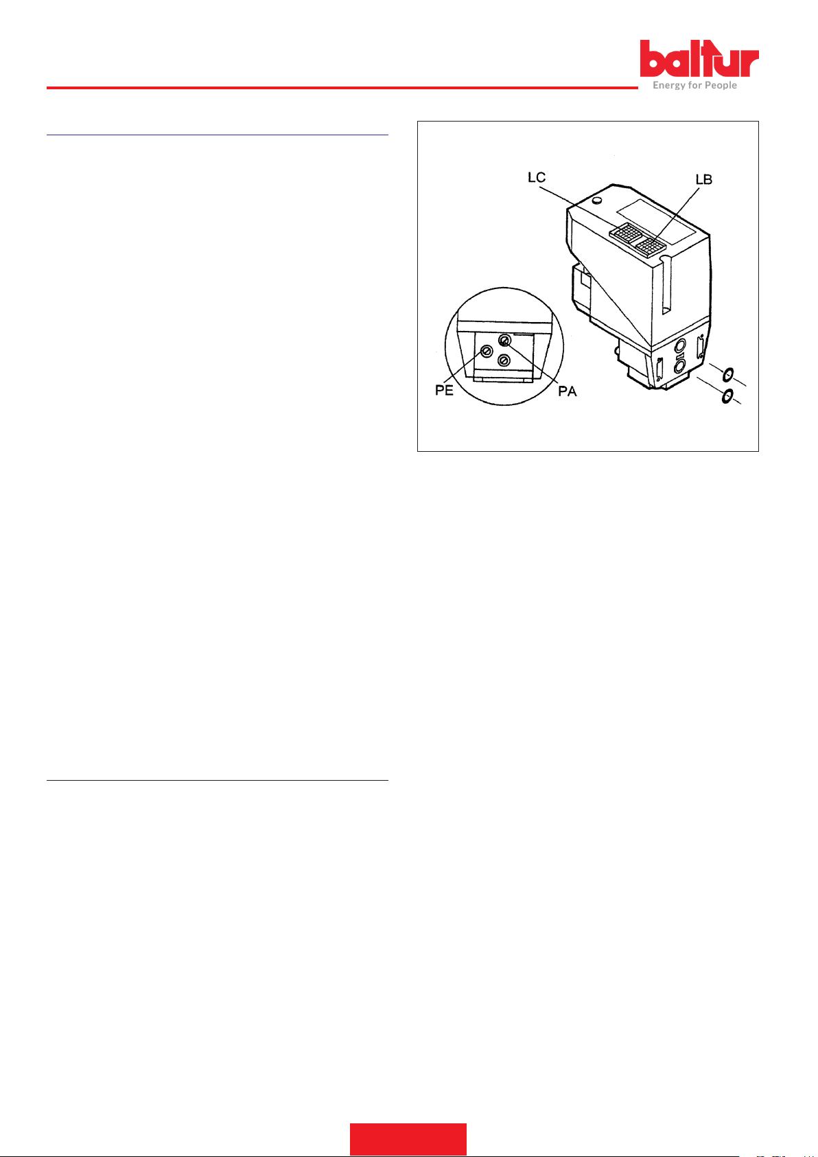
Volendo effettuarne la verica, inserire un manometro in corrispon-
denza della presa di pressione PA.
Se il ciclo di prova ha esito positivo, dopo alcuni secondi si accende
la lampada di consenso LC (gialla).
Per ripartire è necessario sbloccare l’apparecchiatura trmite il pulsante luminoso LB.
Il fusibile è accessibile rimuovendo con un cacciavite il coperchietto
situato vicino alle prese di collegamento elettrico; un fusibile di riserva
è alloggiato nella parte superiore del controllo di tenuta sotto il tappo.
0006160053_201912
10 / 28
Page 13
ACCENSIONE E REGOLAZIONE GAS META-
8922/2
NO
Eseguire un controllo dell’apparecchio alla prima messa in funzione,
dopo ogni revisione e dopo che l’impianto è rimasto inattivo per lungo
tempo.
Prima di qualsiasi operazione d’accensione vericare che la camera
di combustione sia libera da gas.
• effettuando un tentativo di avviamento senza immissione di gas,
si verichi un arresto di blocco alla ne del tempo di sicurezza (o
più ripetizioni di ciclo no ad un massimo di 10, a seconda delle
impostazioni);
• interrompendo l’afusso del gas con l’apparecchio in posizione di
regime, vericare che entro 1s venga tolta tensione alle elettrovalvole gas e, dopo una ripetizione di ciclo (o più ripetizioni di ciclo no
ad un massimo di 10, a seconda delle impostazioni), l’apparecchio
effettui un arresto di blocco;
• i tempi ed il ciclo siano conformi a quelli dichiarati per il tipo di
apparecchio utilizzato;
• il livello del segnale di amma sia sufcientemente elevato;
• gli elettrodi d’accensione siano regolati stabilmente per una distan-
za di scarica in aria fra 2 e 4 mm;
• l’intervento di limitatori o dispositivi di sicurezza provochino il bloc-
co o l’arresto di sicurezza dell’apparecchio conformemente al tipo
di applicazione e alle modalità previste.
• Vericare che lo scarico dei prodotti della combustione attraverso le
serrande caldaia e serrande camino, possa avvenire liberamente.
• Vericare che la tensione della linea elettrica corrisponda a quella
richiesta dal costruttore e, che tutti i collegamenti elettrici realizzati
sul posto, siano eseguiti come da nostro schema elettrico.
• Vericare che ci sia acqua in caldaia e che le saracinesche dell’im-
pianto siano aperte.
• Aprire, della quantità che si presume necessaria, il regolato-
re dell'aria di combustione e aprire di circa un terzo il passaggio
dell'aria tra testa e disco amma (diffusore). Agire sui regolatori
incorporati nella valvola di sicurezza e di funzionamento in modo
da consentire l'erogazione di gas che si presume necessaria.
• Dare corrente al bruciatore inserendo l’interruttore generale.
• Il bruciatore viene così inserito ed effettua la fase di preventilazio-
ne.
• Se il pressostato di controllo della pressione dell’aria rileva una
pressione superiore al valore a cui è regolato, si inserisce il trasformatore d’accensione e, successivamente si inseriscono anche le
valvole gas (di sicurezza e di funzionamento).
• Le valvole si aprono completamente e l’erogazione di gas è limitata
dalla posizione in cui è stato regolato, manualmente, il regolatore
di portata incorporato nella valvola di funzionamento (principale).
ITALIANO
4
3
2
1
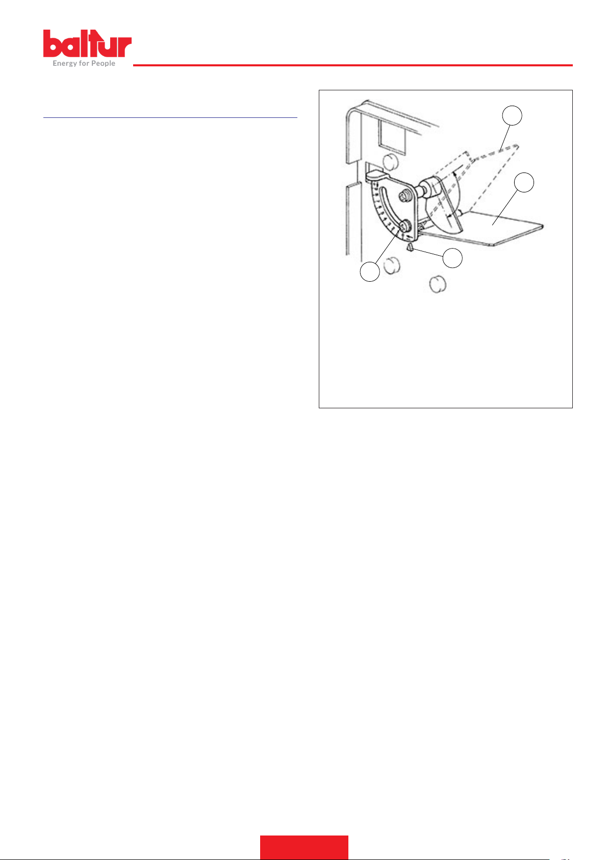
1 Vite di regolazione apertura serranda aria
2 Indice di riferimento apertura serranda aria
3 Serranda chiusa: indice di riferimento in posizione "0"
4 Serranda tutta aperta: indice di riferimento in posizione "0"
• Alla prima accensione possono vericarsi “bloccaggi” successivi
dovuti a:
• La tubazione del gas non è stata sfogata dall’aria in modo suf-
ciente e quindi la quantità di gas è insufciente per consentire una
amma stabile.
• Il “bloccaggio” con presenza di amma, può essere causato da instabilità della stessa nella zona di ionizzazione, per un rapporto
aria gas non corretto.
• Si rimedia variando la quantità di aria e/o di gas erogati in modo da
trovare il corretto rapporto.
• Lo stesso inconveniente puo’ essere causato da una non corretta
distribuzione aria/gas nella testa di combustione.
• Si rimedia agendo sul dispositivo di regolazione della testa di com-
bustione chiudendo o aprendo maggiormente il passaggio dell’aria
tra testa e diffusore gas, attraverso il sistema regolazione disco
amma.
• Può capitare che la corrente di ionizzazione sia contrastata dalla
corrente di scarica del trasformatore di accensione (le due correnti
hanno un percorso in comune sulla “massa” del bruciatore) pertanto il bruciatore si porta in blocco per insufciente ionizzazione.
• Si rimedia vericando la corretta posizione dell’elettrodo di accensione.
• Detto inconveniente può anche essere causato da un insufciente
“messa a terra” della carcassa del bruciatore.
• Il valore minimo della corrente di ionizzazione per assicurare il fun-
zionamento dell’apparecchiatura è presente sullo schema elettrico.
11 / 28
0006160053_201912
Page 14
3
0002939070
ITALIANO
• Con bruciatore acceso adeguare la portata al valore desiderato;
effettuando la lettura al contatore.
• Detta portata può essere modicata agendo sull’apposito regolato-
re incorporato alla valvola, vedere nelle pagine seguenti la descrizione della regolazione delle valvole.
• Controllare, mediante gli appositi strumenti, che la combustione
avvenga correttamente (CO2 max.= circa 10% per metano - CO
max. = 0,1 %).
• Dopo aver effettuato la regolazione occorre spegnere e riaccende-
re alcune volte il bruciatore per vericare che l’accensione avvenga
regolarmente.
• Quando il bruciatore è acceso occorre vericare, come esposto
precedentemente, l’erogazione di gas e la combustione con gli appositi strumenti. In funzione dei rilievi effettuati si procede variando,
se necessario, l’erogazione del gas e della relativa aria di combustione per adeguare l’erogazione al valore desiderato per il caso
specico (potenza caldaia) ovviamente occorre anche vericare
che i valori della CO2 e del CO siano adeguati (CO2 max. = circa
10 % per metano e CO = 0,1%).
• Controllare l’efcienza dei dispositivi di sicurezza, blocco (staccan-
do il cavo dell’elettrodo di ionizzazione) pressostato aria, pressostato gas, termostati.
1
IMPORTANTE
Il circuito di collegamento del pressostato prevede l’ autocon-
trollo, quindi, è necessario che il contatto previsto per essere
chiuso a riposo (ventola ferma e di conseguenza assenza di
pressione aria nel bruciatore), realizzi effettivamente questa
condizione, in caso contrario l’ apparecchiatura di comando e
controllo non viene inserita (il bruciatore resta fermo).
• Vericare che lo scarico dei prodotti della combustione attraverso le
serrande caldaia e serrande camino, possa avvenire liberamente.
• Precisiamo che se non si chiude il contatto previsto per essere
chiuso in lavoro, l’ apparecchiatura esegue il suo ciclo ma non si
inserisce il trasformatore d’ accensione e non si aprono le valvole
del gas, di conseguenza il bruciatore si arresta in “blocco”.
• Per accertare il corretto funzionamento del pressostato aria occor-
re, con bruciatore acceso,aumentarne il valore di regolazione no
a vericarne l’ intervento a cui deve conseguire l’ immediato arresto
in “blocco” del bruciatore.
• Sbloccare il bruciatore, premendo l’apposito pulsante e riportare la
regolazione del pressostato ad un valore sufciente per rilevare la
pressione di aria esistente durante la fase di preventilazione.
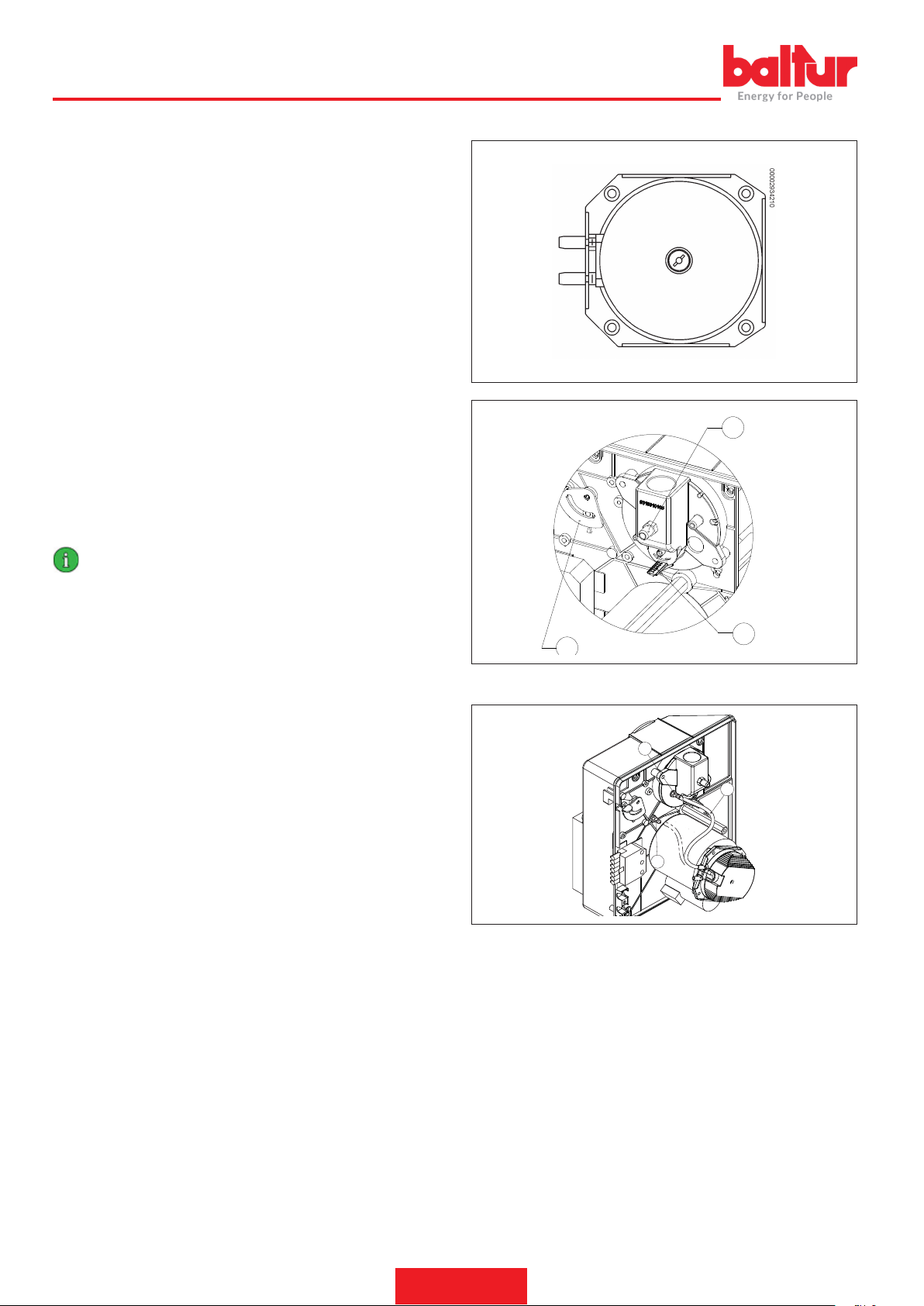
PRESSOSTATO ARIA
Eseguire la regolazione del pressostato aria dopo aver effettuato tutte
le altre regolazioni del bruciatore con il pressostato aria regolato a
inizio scala.
Con il bruciatore funzionante alla potenza richiesta, agire sulla vite
centrale lentamente in senso orario no al blocco del bruciatore.
Ruotare quindi in senso antiorario la vite di circa 1/2 giro e ripetere
l’avviamento del bruciatore per vericarne la regolarità.
Se il bruciatore si blocca nuovamente, ruotare ancora la manopola
di 1/2 giro.
Il pressostato aria ha lo scopo di mettere in sicurezza (blocco) l’apparecchiatura se la pressione dell’aria non è quella prevista.
Qualora il pressostato aria non rilevi una pressione superiore a quella
di taratura, l'apparecchiatura esegue il suo ciclo ma non si inserisce
il trasformatore d'accensione e non si aprono le valvole del gas e di
conseguenza il bruciatore si arresta in "blocco"
2
INSTALLAZIONE BRUCIATORE SU IMPIANTI INDUSTRIALI
A
B
0002939510
C
Qualora il pressostato aria riceva un valore inferiore al minimo di
taratura, occorre togliere il tubo "C" dalla presa di pressione "A" e
collegarlo alla presa di pressione "B".
Al termine ripetere nuovamente la regolazione del pressostato aria.
12 / 28
0006160053_201912
Page 15
CORRENTE IONIZZAZIONE
3
0002939070
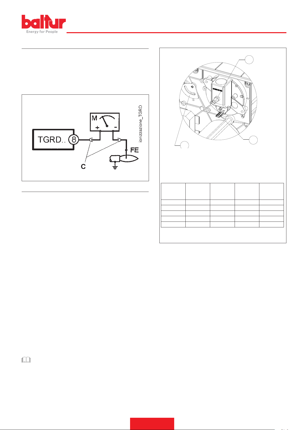
Il valore minimo della corrente di ionizzazione necessario a far funzio-
nare l'apparecchiatura, è riportato nello schema elettrico.
Il bruciatore dà una corrente nettamente superiore, tale da non richie-
dere normalmente alcun controllo.
Per misurare la corrente di ionizzazione bisogna collegare un microamperometro in serie al cavetto dell'elettrodo di ionizzazione aprendo
il connettore "C" come rappresentato in gura.
ITALIANO
1
2
1 - Presa di pressione P3
2 - Indice posizione disco miscelatore
3 - Indice serranda
DATI INDICATIVI REGOLAZIONE POTENZA
REGOLAZIONE ARIA SULLA TESTA DI COMBUSTIONE
La testa di combustione è dotata di un dispositivo di regolazione che
permette di aprire o chiudere il passaggio dell’aria tra il disco e la
testa. Chiudendo il passaggio si riesce così ad ottenere, un’elevata
pressione a monte del disco anche con le basse portate. L’elevata velocità e turbolenza dell’aria consente una migliore penetrazione della
stessa nel combustibile e quindi, un’ottima miscela e stabilità di amma. Può essere indispensabile avere un’elevata pressione d’aria a
monte del disco, per evitare pulsazioni di amma, questa condizione
è praticamente indispensabile quando il bruciatore lavora su focolare
pressurizzato e/o ad alto carico termico.
Il dispositivo che chiude l’aria sulla testa di combustione deve essere
portato in una posizione tale da ottenere sempre dietro al disco un
valore decisamente elevato della pressione dell’aria. Quando il bruciatore lavora alla massima erogazione, regolare la chiusura dell'aria
sulla testa, tale da richiedere una sensibile apertura della serranda
che regola il usso aria. Iniziare quindi la regolazione con il dispositivo che chiude l'aria sulla testa di combustione in una posizione
intermedia, accendendo il bruciatore per una regolazione orientativa
come esposto precedentemente. Spostare in avanti o indietro la testa
di combustione in modo da avere un usso d'aria adeguato all'erogazione.
Raggiunta |b|l'erogazione masssima desiderata|bb| si provvede a
correggere la posizione del dispositivo che chiude l'aria sulla testa
di combustione, spostandolo in avanti o indietro, in modo di avere un
usso d'aria, adeguato all'erogazione, |b|con serranda di regolazione
dell'aria in aspirazione sensibilmente aperta.|bb|
Potenza kW
35 2 2 1.8 1.5
55 3 3 2.2 1.8
75 4,5 4.5 2.9 2.2
95 6 6 4.3 3.2
115 9 9 5.5 1.3
Posizione
serranda aria
Posizione
Disco misce-
latore
Pressione
P3 metano
mbar
Pressione P3
GPL mbar
CAUTELA / AVVERTENZE
Controllare che l'accensione avvenga regolarmente agendo
per gradi sulla vite di regolazione disco - testa, no a raggiungere una posizione in cui l'accensione avviene regolarmente.
Per il primo stadio, limitare la quantità d'aria allo stretto indi-
spensabile per avere un'accensione sicura anche nei casi più
impegnativi.
13 / 28
0006160053_201912
Page 16
ITALIANO
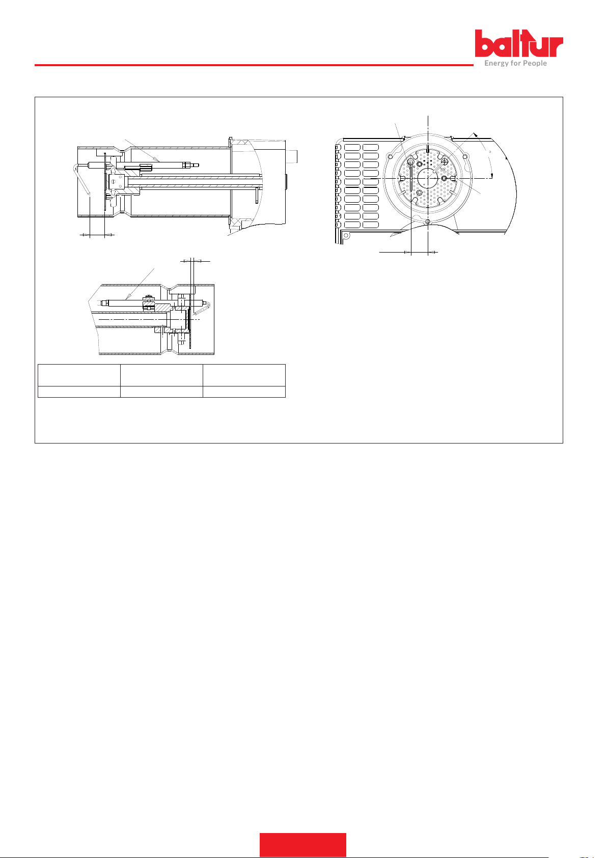
SCHEMA DI REGOLAZIONE TESTA DI COMBUSTIONE E DISTANZA DISCO ELETTRODI
7
A
A
8
0002939080
7
45
8
21.5
A 20 mm 4-5 mm
Elettrodo Ionizzatore
pos. 7
Elettrodo Accensione
pos. 8
14 / 28
0006160053_201912
Page 17

ITALIANO
APPARECCHIATURA DI COMANDO E CONTROLLO TGRD 61
La seguente descrizione fa riferimento ai dispositivi di controllo dotati di ciclo di funzionamento standard. Ad ogni avviamento il dispositivo effet-
tua un’autoverica della propria efcienza.
Durante il tempo di attesa (TW) o preventilazione (TP) il circuito interno controlla il corretto funzionamento dell’amplicatore del segnale di amma: un segnale di amma parassita o un guasto dell’amplicatore che corrisponda alle condizioni di amma presente impediscono l’avviamento
dell’apparecchio.
Nei tipi in cui è previsto il comando del ventilatore, prima dell’inizio del tempo di preventilazione (TP), viene vericato che il contatto del pressostato aria si trovi nella posizione di assenza d’aria e solo se tale verica ha esito positivo la commutazione del pressostato consente l’inizio della
fase di preventilazione (TP).
La verica dei contatti del pressostato aria viene effettuata ad ogni inizio di ciclo.
Alla ne del tempo di attesa (TW) o di preventilazione (TP) viene alimentata l’elettrovalvola gas EV1 e avviato il dispositivo di accensione, dando
così inizio al tempo di sicurezza (TS).
Se durante il tempo di sicurezza l’apparecchio rivela un segnale di amma, il dispositivo di accensione viene inibito e, nei modelli che lo prevedono, viene alimentata la valvola principale EV2.
Se invece l’apparecchio non rivela alcun segnale di amma nel corso del tempo di sicurezza, allo scadere dello stesso si verica un arresto di
blocco, per cui vengono chiuse le l’elettrovalvole, viene inibito il dispositivo di accensione e viene alimentata la segnalazione di blocco.
Per meglio comprendere il funzionamento dei singoli apparecchi, si rimanda ai diagrammi di ciclo.
DIAGNOSI DELLE CAUSE DI MALFUNZIONAMENTO E BLOCCO.
In caso di blocco premendo il pulsante di sblocco per più di 5 sec., la fase di diagnosi verrà attivata (segnalazione d’allarme con lampeggio).
La segnalazione d’allarme viene spenta per un numero di volte che dipende dal tipo di blocco con una pausa di 2 sec. tra una serie di lampeggi
e l’altra.
Nella tabella sottostante viene riportato il signicato della causa di blocco o malfunzionamento in funzione del numero di lampeggi.
Tabella dei codici di errore
Codice di lampeggio della segnalazione
d’allarme (led rosso)
2 lampeggi
●●
3 lampeggi
●●●
4 lampeggi
●●●●
5 lampeggi
●●●●●
6 lampeggi
●●●●●●
7 lampeggi
●●●●●●●
8 - 14 lampeggi Guasto interno generico.
Possibili cause
Assenza del segnale di amma alla ne del tempo di sicurezza <TS>
- Malfunzionamento valvole combustibile
- Malfunzionamento rilevatore amma
- Difettosità nella taratura del bruciatore, assenza di combustibile
- Mancata accensione difettosità trasformatore di accensione
Pressostato aria non chiude o le rotazioni per minuto sono inferiori al minimo impostato (TGR-
D6x-TGRD8x). Termostato Preriscaldo non chiude (TGRD7x-TGRD9x). Termostato sicurezza non
chiude (TGRDxx).
Luce estranea durante la fase di accensione
Pressostato aria non apre o presenza di rotazioni per minuto superiori al minimo impostato
(TGR6x-TGR8x).
Perdita pressostato aria o le rotazioni per minuto, a regime, sono inferiori al minimo impostato
(TGR6x-TGR8x). Perdita Termostato sicurezza a regime (TGRDxx).
Mancanza amma a regime
15 / 28
0006160053_201912
Page 18
ITALIANO
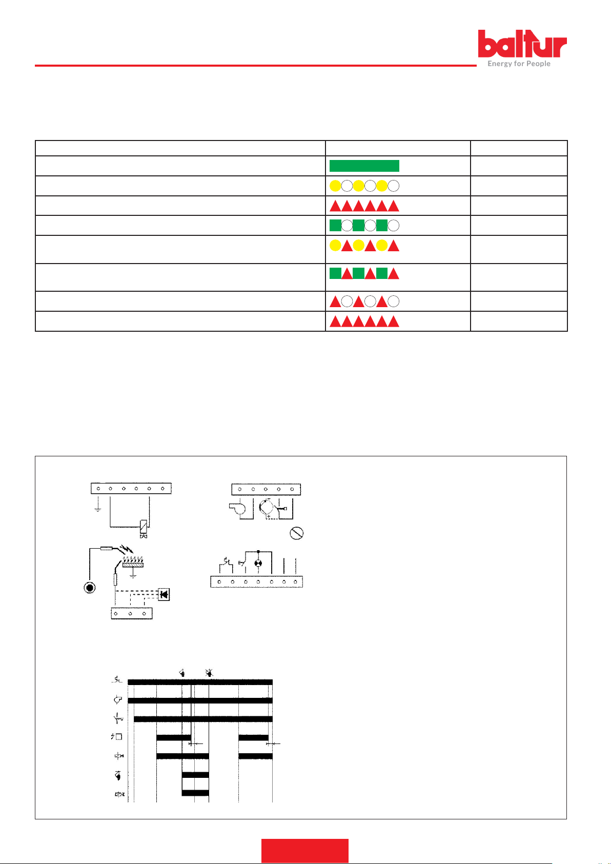
SEGNALAZIONI DURANTE IL FUNZIONAMENTO
Nelle varie condizioni di funzionamento l’apparecchio è in grado di segnalare lo stato di funzionamento mediante LED multicolore disposto in
corrispondenza della segnalazione di blocco a bordo.
Di seguito è riportata la legenda dei colori:
Condizione Sequenza colori Colori
Stato di buon funzionamento con buon segnale di amma Verde
Fase di accensione Arancio
Condizione di blocco bruciatore Rosso
Stato di funzionamento con scarso segnale di amma Verde intermittente
Segnalazione di bassa/alta tensione Rosso e Arancio
alternati
Stato di accensione con scarso segnale di amma Verde Arancio alter-
nati
Stato di accensione con buon segnale di amma Arancio intermittente
Diagnostica nello stato di blocco o amma parassita Rosso intermittente
A richiesta, è possibile variare le segnalazioni dello stato di funzionamento del LED multicolore
SBLOCCO DELL’APPARECCHIO
Blocco non volatile (riarmo manuale)
Quando l’apparecchio si porta in condizione di blocco non volatile, per sbloccare il sistema è necessario agire sul pulsante di riarmo sino allo
spegnimento della segnalazione di blocco (< 5 secondi).
Blocco volatile (riarmo elettrico)
l riarmo dell’apparecchio da una condizione di blocco volatile è possibile mediante interruzione e successivo ripristino dell’alimentazione elettrica.
Non è possibile sbloccare il sistema mediante spegnimento del dispositivo di richiesta calore.
SCHEMA DEI COLLEGAMENTI
EVP Valvola Pilota
16 17 18 19 20 21
J3
ACC
ION
J5
W
J4
8 9 10
T
V
PA
A
EV1
ION
EV1
J1
BC
FD
TSP TSP
1s 1s
11 12 13 14 15
J2
RPM
V
SB
RE
T
1 2 3 4 5
PA
N L
6 7
F1
schema_coll_TGRD
diagr_ciclo_TGRD
FR Fotoresistenza
FD Fotodiodo
ION Elettrodo ionizzazione
T Termostato Ambiente
RISC Preriscaldatore combustibile
TC Termostato Preriscaldatore
RPM Rotazioni per minuto
PA Pressostato aria
V Motore bruciatore
TR Trasformatore Accensione
RE Reset
EV1 Valvola Principale
EV2 Valvola secondo stadio
SB Segnalazione di Blocco
TS Tempo di sicurezza
TP Tempo di Preventilazione
TPS Tempo accensione scintilla
Tj Tempo di Pre-accensione
EV2
16 / 28
0006160053_201912
Page 19
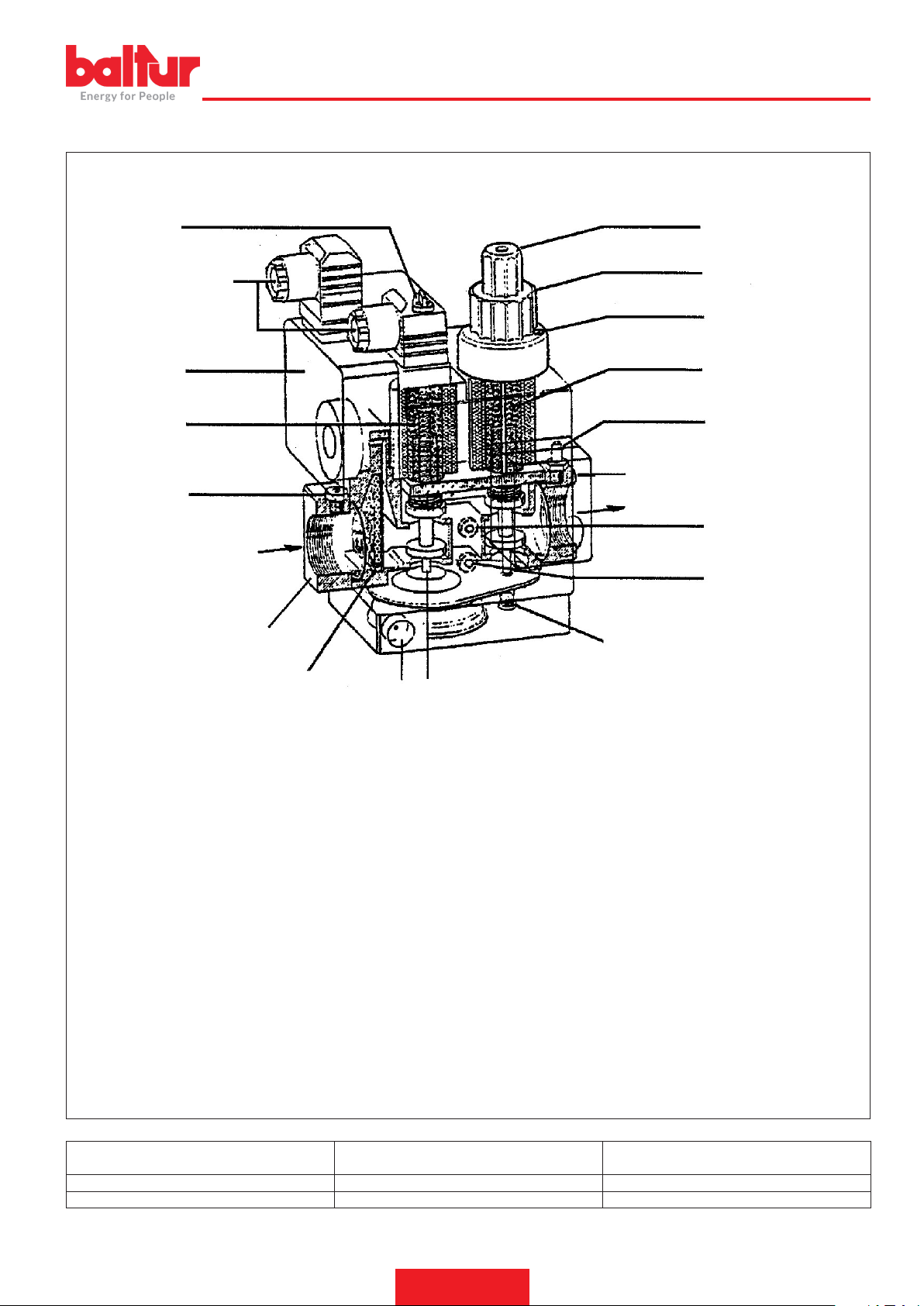
VALVOLA GAS COMBINATA (MONOBLOCCO) DUNGS MOD. MB-DLE ... B01
0002910301
1 2
ITALIANO
14
6
13
A
B
15
12
11
3
4
5
7
17
8 (Pa)
9 (Pa)
16
10
A Collegamenti elettrici
B Senso del usso
1 Accesso alla vite regolazione stabilizzatore
2 Manopola di accesso per manovra regolatore della portata di
accensione
3 Manopola di regolazione erogazione massima loccaggio manopola di regoalzione
4 Vite in bloccaggio
5 Valvola principale (apertura in due tempi)
6 Valvola di sicurezza (rapida)
7 Presa di pressione (controllo pressione uscita valvola)
8 Presa di pressione in uscita dello stabilizzatore (Pa)
9 Pressa di pressione ingresso valvola (Pe)
Valvola modello Pressione max ingresso (PE) mbar
MB …403 B01 S 20 200 da 4 a 20
MB … … B01 S 20 360 da 4 a 20
10 Stabilizzatore di presione
11 Sato dello stabilizzatore di pressione
12 Filtrino di ingresso
13 Presa di pressione ingresso valvola
14 Pressostato di minima pressione
15 Flangia entrata
16 Tappo
17 Flangia uscita
Pressione regolabile in uscita stabilizzatore (Pa)
mbar
17 / 28
0006160053_201912
Page 20

ITALIANO
Il gruppo valvole gas DUNGS MB-DLE... è costituito da:
• Valvola di sicurezza ad apertura rapida e chiusura rapida (6).
• Valvola principale (5) ad apertura in due tempi. Il primo tempo di
apertura avviene rapidamente (a scatto) ed è regolabile svitando
la manopola (2) ed inserendola rovesciata sul perno sottostante di
regolazione. Sulla testa della valvola sono riportati i simboli + e -
che indicano in quale senso occorre ruotare il pomello per ottenere
una variazione della portata di gas all'accensione (primo tempo di
apertura della valvola). Ruotando in senso orario l’erogazione d’accensione diminuisce, con rotazione in senso antiorario l’erogazione
aumenta. La corsa completa da zero al massimo si realizza con
una rotazione di poco superiore ai tre giri completi (40% dell’apertura totale) e viceversa. Al termine del primo scatto l’apertura della
valvola prosegue lentamente ed in 15 secondi raggiunge l’apertura
massima. La regolazione dell'erogazione massima desiderata si
effettua allentando la vite con testa sporgente di bloccaggio (4) e
ruotando la manopola (3). Non toccare la vite con sigillo in vernice.
Ruotando in senso orario l’erogazione diminuisce, in senso antiorario l’erogazione aumenta. Precisiamo che ruotando la manopola
si sposta il ne corsa che limita l’apertura della valvola pertanto
quando la manopola di regolazione è tutta ruotata verso il segno
- la valvola non si apre, quindi il bruciatore non si accende. Per
ottenere l’accensione occorre ruotare in senso antiorario, verso il
segno + la manopola. La corsa completa da zero al massimo e viceversa si ottiene ruotando la manopola per quasi sei giri completi.
L’operazione di regolazione della portata massima e di accensione
deve essere effettuata senza forzare contro i rispettivi ne corsa.
• Lo stabilizzatore di pressione (10) viene regolato (vedi tabella),
tramite la vite accessibile facendo scorrere lateralmente il coper-
chietto (1). La corsa completa dal minimo al massimo e viceversa
richiede circa 80 giri completi, non forzare contro i ne corsa. Attorno all’orizio di accesso sono riportate le frecce con i simboli che
indicano il senso di rotazione, per l’aumento (rotazione in senso
orario) o diminuzione (rotazione in senso antiorario) della pressio-
ne. Detto stabilizzatore realizza la chiusura ermetica tra “monte” e
“valle” quando manca il usso. Non sono previste molle diverse per
ottenere valori di pressione diversi da quelli sopra esposti. |bb|Per
la regolazione dello stabilizzatore di pressione collegare il mano-
metro ad acqua al portagomma installato alla presa (8) corrispon-
dente all’uscita dello stabilizzatore (Pa). |bb|
• Filtrino di ingresso (12) accessibile per la pulizia asportando una
delle due piastrine laterali di chiusura.
• Pressostato (14) di minima pressione gas. Per la regolazione, occorre asportare il coperchio trasparente ed agire sulla manopola
nera. L’indice di riferimento è un piccolo rettangolo riportato sul disco giallo attorno al quale ruota la manopola di regolazione.
• All’ingresso, sulla angia di attacco, è prevista una presa (13) per
il rilevamento della pressione di ingresso. All’uscita sulla angia di
attacco, è prevista una presa (7) per il rilevamento della pressione
di uscita.
• Le prese di pressione laterali (9), indicate con Pe, sono in comunicazione con la pressione di ingresso.
• Le prese di pressioni laterali (8), indicate con (Pa), servono per
rilevare la pressione in uscita dallo stabilizzatore. É bene sapere che la pressione in uscita del gruppo valvole (7) corrisponde
alla pressione regolata dallo stabilizzatore, diminuita della pressione necessaria a vincere la resistenza di attraversamento della valvola principale (5). Le resistenze di attraversamento valvola
sono variabili in funzione dell'apertura della valvola, regolata dalla
manopola (3) con cui si sposta il ne corsa. |b|Per la regolazione
dello stabilizzatore di pressione collegare il manometro ad acqua al
portagomma installato alla presa (8) corrispondente all’uscita dallo
stabilizzatore (Pa).|bb|
• Sato (11) dello stabilizzatore di pressione, per un corretto funzionamento i fori di sato devono essere liberi.
CONSIGLI DI REGOLAZIONE DELLA VALVOLA GAS
• Collegare il manometro ad acqua alla presa di pressione Pa (8)
per rilevare la pressione in uscita dello stabilizzatore.
• Portare i regolatori della erogazione del gas per l’accensione (2) e
quella per la portata massima (3) nella posizione che si presume
necessaria per l'erogazione desiderata. Aprire anche adeguata-
mente il regolatore dell’aria di combustione.
• Accendere il bruciatore.
• Con bruciatore acceso, agire sotto il coperchietto (1) sulla vite di
regolazione dello stabilizzatore di pressione del gas e regolare la
pressione al valore necessario per ottenere la portata desiderata,
circa 40 ÷ 70 mm.C.A. quando il regolatore di portata massima (3)
è nella posizione di massima apertura.
• Portare il regolatore della portata di accensione (2), nella posizione necessaria per ottenere l’accensione con la minima erogazione
possibile.
CAUTELA / AVVERTENZE
Con accensioni irregolari, regolare la pressione allo stabilizzatore (8) a 20 mbar.
18 / 28
0006160053_201912
Page 21
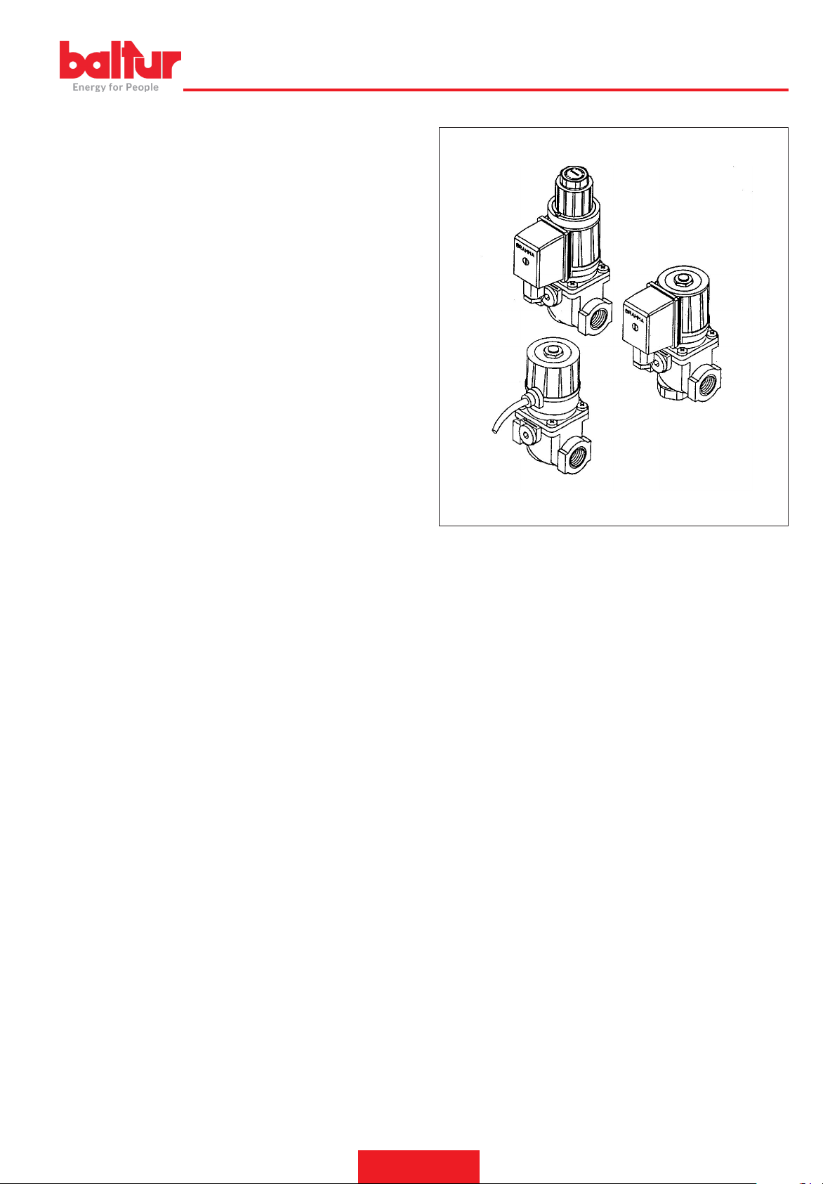
ELETTROVALVOLA PER BRUCIATORI DI GAS (BASSA PRESSIONE) BRAHMA MOD. EG 12*... E E 6G*
ITALIANO
DESCRIZIONE
Con la sigla EG 12*S... viene identicato un tipo di valvola normalmente a chiusura rapida, ad apertura rapida o lenta con scatto rapido
regolabile per la portata iniziale.
La EG 12*S... (g.1) e la EG 12*L sono alimentate in corrente alternata ma con un circuito raddrizzatore integrato, la bobina viene
alimentata con corrente continua.
Tutte le EG 12*... sono corredate di due raccordi per il montaggio di
prese di pressione,
Ogni valvola a monte è munita di un ltro per evitare l’ingresso di
particelle solide di dimensioni maggiori di 1 mm.
L’elettrovalvola EG 12*SR... (g.2) si differenzia dalla EG 12*S... per
la presenza a valle di un dispositivo atto a regolare la portata.
L’elettrovalvola EG 12*L... (g.3) consente l’accensione progressiva
del bruciatore in quanto la sua apertura viene ritardata da un apposito
ammortizzatore oleodinamico posto a diretto contatto con l’equipag-
gio mobile.
L’elettrovalvola EG 12*L... presenta sia la regolazione del tempo di
apertura, sia la possibilità di regolare lo scatto rapido per la portata
iniziale.
É possibile, inoltre, regolare la portata massima agendo sull’intero
blocco ammortizzante.
CARATTERISTICHE TECNICHE
Classe: A.
gruppo: 2
Alimentazione: 110-230 Vac / 50-60 Hz (sono disponibili versioni con
diverse tensioni di alimentazione)
Temperatura di esercizio: – 10 / + 60° C
Massima pressione di esercizio garantita: 500 mbar.
Posizione di montaggio verticale o orizzontale.
Tempo di chiusura ≤ 1 s.
Tempo di apertura ≤ 1 s.
Classe: A Temperatura di esercizio: – 10° C / + 60° C.
Molla in acciaio inossidabile, Alimentazione: 230V 50/60 Hz.
Rivestimento bobina: PA6 Grado di protezione: IP54.
Corpo alluminio pressofuso.
Pressacavi: PG9.
Fig.3
0002910220d
Fig.2
Fig.1
19 / 28
0006160053_201912
Page 22
0002910220
ITALIANO
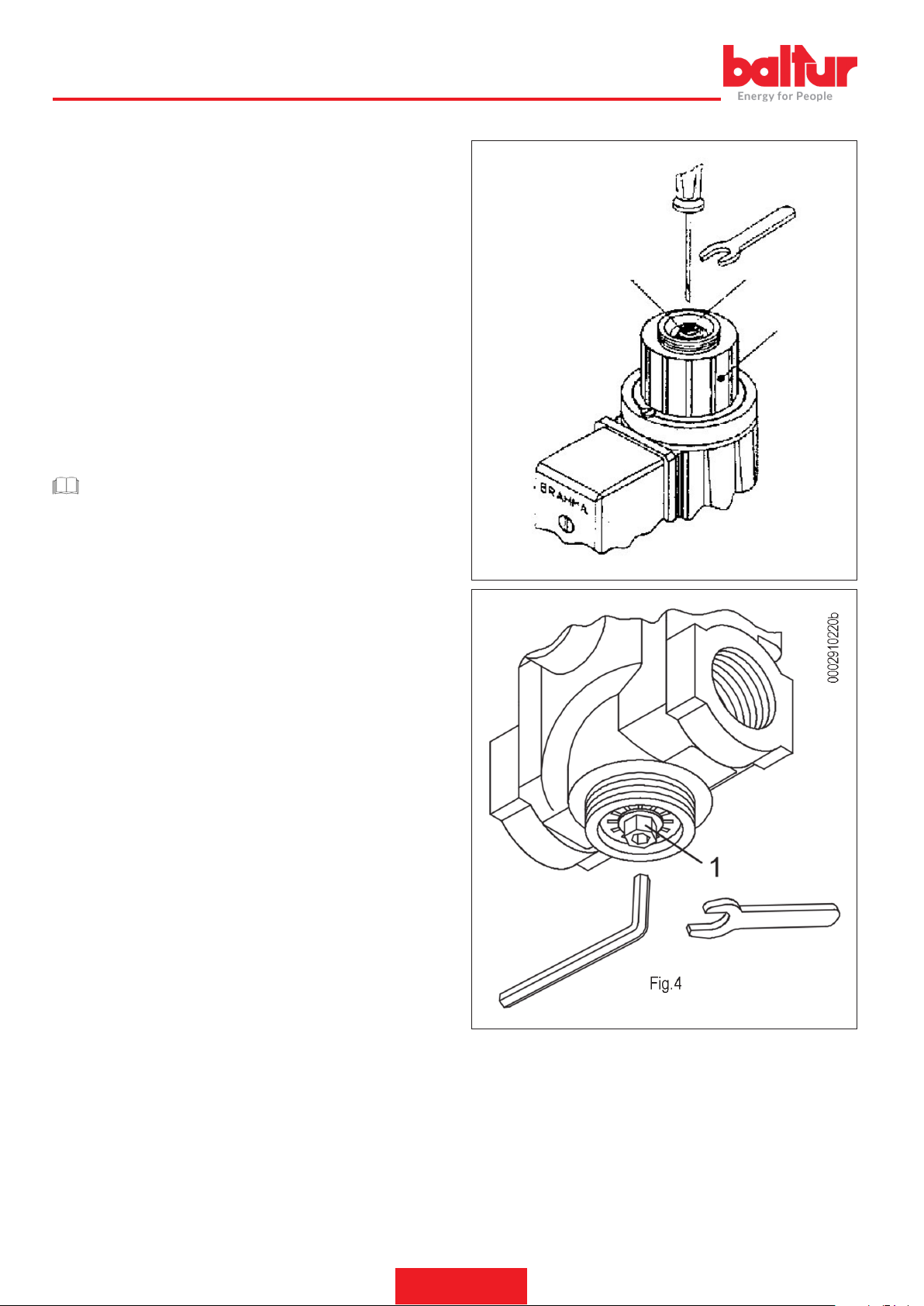
ISTRUZIONI PER LA REGOLAZIONE DELLA ELETTROVALVOLA EG 12*L ... E E 6G*
Regolazione della portata
Per poter variare la portata di gas sul bruciatore agire sull’intero blocco 3 del gruppo ritardatore rappresentato in g. 4.
Allentare la vite di bloccaggio della calotta (svitare solo quella priva di
vernice bloccante) e ruotare l’intero gruppo.
Agendo in senso orario si ottiene la diminuzione della portata, inversamente se ne ha l’aumento.
I ne corsa della regolazione sono garantiti dalla battuta di arresto
del letto del regolatore e da un anello di spallamento, entrambi situa-
ti all’interno della guaina.
Regolazione del tempo di apertura della valvola:
Si ottiene agendo sulla vite di regolazione 1 indicata in g. 4.
Agendo in senso orario, la vite tende ad occludere il foro di passaggio
dell’olio ottenendo un tempo di apertura della valvola lungo. Inversamente, in senso antiorario, il tempo di apertura diminuisce in quanto
la vite libera la sezione di afusso dell’olio.
CAUTELA / AVVERTENZE
La vite di regolazione 1 è già regolata dalla Casa Costruttrice,
pertanto non toccare.
Regolazione dello scatto rapido della portata iniziale:
É ottenuta tramite la rotazione del regolatore 2 indicato in g. 4.
Ruotando, mediante una chiave esagonale da 6, in senso orario, lo
scatto rapido diminuisce, inversamente si ottiene un aumento.
2
2
1
3
Fig. 4
ISTRUZIONI PER LA REGOLAZIONE DELLA ELETTROVALVOLA EG12*AR-EG 12*SR
Regolazione della portata:
Per poter variare la portata di gas bisogna agire sul regolatore A mediante chiave esagonale da 8 mm.
Oppure chiave per esagono incassato da 4 mm.
Ruotando in senso orario si ottiene la riduzione di portata; in senso
antiorario si ha un aumento della portata.
20 / 28
0006160053_201912
Page 23

MANUTENZIONE
Effettuare almeno una volta all’anno e comunque in conformità alle
norme vigenti, l’analisi dei gas di scarico della combustione vericando la correttezza dei valori di emissioni.
• Pulire le serrande aria, il pressostato aria con presa di pressione ed
il relativo tubo se presenti.
• Vericare lo stato degli elettrodi. Se necessario sostituirli.
• Pulire la fotocellula. Se necessario sostituirla.
• Far pulire la caldaia ed il camino da personale specializzato in fumisteria, una caldaia pulita ha maggior rendimento, durata e silenziosità.
• Controllare che il ltro del combustibile sia pulito. Se necessario
sostituirlo.
• Vericare che tutti i componenti della testa di combustione siano
in buono stato, non deformati e privi di impurità o depositi derivanti
dall'ambiente di installazione e/o da una cattiva combustione.
• Effettuare l’analisi dei gas di scarico della combustione vericando
la correttezza dei valori di emissioni.
ITALIANO
21 / 28
0006160053_201912
Page 24

ITALIANO
TEMPI DI MANUTENZIONE
Descrizione particolare Azione da eseguire Gas
TESTA DI COMBUSTIONE
ELETTRODI
DISCO FIAMMA CONTROLLO VISIVO INTEGRITA' EVENTUALI DEFORMAZIONI, PULIZIA ANNUO
SONDA DI IONIZZAZIONE
COMPONENTI TESTA COMBU-
STIONE
GUARNIZIONE ISOLANTE CONTROLLO VISIVO TENUTA ED EVENTUALE SOSTITUZIONE ANNUO
GUARNIZIONE RACCORDO
MANDATA GAS
GRIGLIA/SERRANDE ARIA PULIZIA ANNO
CUSCINETTI SERRANDA ARIA INGRASSAGGIO ANNO
VENTILATORE PULIZIA VENTOLA E CHIOCCIOLA, INGRASSAGGIO ALBERO MOTORE ANNO
PRESSOSTATO ARIA PULIZIA ANNO
PRESA E CONDOTTI PRESSIO-
NE ARIA
SENSORE FIAMMA PULIZIA ANNO
PRESSOSTATO GAS VERIFICA FUNZIONALE ANNO
MOTORI ELETTRICI PULIZIA VENTOLA RAFFREDDAMENTO, VERIFICA RUMOROSITÁ CUSCINETTI ANNO
CAMMA MECCANICA VERIFICA USURA E FUNZIONALITÁ, INGRASSAGGIO PATTINO E VITI ANNO
LEVE/TIRANTI/SNODI SFERICI CONTROLLO EVENTUALI USURE, LUBRIFICAZIONE COMPONENTI ANNO
IMPIANTO ELETTRICO VERIFICA CONNESSIONI E SERRAGGIO MORSETTI ANNO
INVERTER PULIZIA VENTOLA DI RAFFREDDAMENTO E SERRAGGIO MORSETTI ANNO
SONDA CO PULIZIA E CALIBRAZIONE ANNO
SONDA O2 PULIZIA E CALIBRAZIONE ANNO
KIT ESTRAZIONE TESTA COM-
BUSTIONE
FILTRO GAS SOSTITUIRE ELEMENTO FILTRANTE ANNO
TENUTE IDRAULICHE/GAS VERIFICA EVENTUALI PERDITE ANNO
CONTROLLO CO CONFRONTO CON VALORI REGISTRATI ALL'AVVIAMENTO DEL'IMPIANTO ANNO
CONTROLLO CO2 CONFRONTO CON VALORI REGISTRATI ALL'AVVIAMENTO DEL'IMPIANTO ANNO
CONTROLLO INDICE DI FUMO
BACHARACH
CONTROLLO NOX CONFRONTO CON VALORI REGISTRATI ALL'AVVIAMENTO DEL'IMPIANTO ANNO
CONTROLLO CORRENTE DI
IONIZZAZIONE
CONTROLLO TEMPERATURA
FUMI
REGOLATORE PRESSIONE
GAS
CONTROLLO VISIVO, INTEGRITA' CERAMICHE, SMERIGLIATURA ESTREMITA', VERIFICARE
DISTANZA, VERIFICARE CONNESSIONE ELETTRICA
CONTROLLO VISIVO, INTEGRITA' CERAMICHE, SMERIGLIATURA ESTREMITA', VERIFICARE
DISTANZA, VERIFICARE CONNESSIONE ELETTRICA
CONTROLLO VISIVO INTEGRITA' EVENTUALI DEFORMAZIONI, PULIZIA ANNUO
CONTROLLO VISIVO TENUTA ED EVENTUALE SOSTITUZIONE ANNUO
LINEA ARIA
PULIZIA ANNO
COMPONENTI DI SICUREZZA
COMPONENTI VARI
VERIFICA USURA E FUNZIONALITÁ ANNO
LINEA COMBUSTIBILE
PARAMETRI DI COMBUSTIONE
CONFRONTO CON VALORI REGISTRATI ALL'AVVIAMENTO DEL'IMPIANTO N.A.
CONFRONTO CON VALORI REGISTRATI ALL'AVVIAMENTO DEL'IMPIANTO ANNO
CONFRONTO CON VALORI REGISTRATI ALL'AVVIAMENTO DEL'IMPIANTO ANNO
RILIEVO PRESSIONE ALL'AVVIAMENTO ANNO
ANNUO
ANNUO
IMPORTANTE
Per utilizzi gravosi o con combustibili particolari, gli intervalli tra una manutenzione e la successiva, dovranno essere ridotti adeguandoli
alle effettive condizioni di impiego secondo le indicazioni del manutentore.
22 / 28
0006160053_201912
Page 25

ITALIANO
VITA ATTESA
La vita attesa dei bruciatori e dei relativi componenti dipende molto dal tipo di applicazione su cui il bruciatore è installato, dai cicli, dalla potenza
erogata, dalle condizioni dell’ambiente in cui si trova, dalla frequenza e modalità di manutenzione, ecc. ecc.
Le normative relative ai componenti di sicurezza prevedono una vita attesa di progetto espressa in cicli e/o anni di funzionamento.
Tali componenti garantiscono un corretto funzionamento in condizioni operative "normali" (*) con manutenzione periodica secondo le indicazioni
riportate nel manuale.
La seguente tabella illustra la vita attesa di progetto dei principali componenti di sicurezza; i cicli di funzionamento indicativamente corrispondono
alle partenze del bruciatore.
|b|In prossimità del raggiungimento di tale limite di vita attesa il componente deve essere sostituito con un ricambio originale|bb|.
IMPORTANTE
le condizioni di garanzia (eventualmente ssate in contratti e/o note di consegna o di pagamento) sono indipendenti e non fanno riferimento alla vita attesa di seguito indicata.
(*) Per condizioni operative “normali” si intendono applicazioni su caldaie ad acqua e generatori di vapore oppure applicazioni industriali conformi
alla norma EN 746, in ambienti con temperature nei limiti previsti dal presente manuale e con grado di inquinamento 2 conformemente all’alle-
gato M della norma EN 60335-1.
Componente di sicurezza
Apparecchiatura 250 000 10
Sensore amma (1) n.a. 10 000 ore di funzionamento
Controllo di tenuta 250 000 10
Pressostato gas 50 000 10
Pressostato aria 250 000 10
Regolatore di pressione gas (1) n.a. 15
Valvole gas (con controllo di tenuta) Sino alla segnalazione della prima anomalia di tenuta
Valvole gas (senza controllo di tenuta) (2) 250 000 10
Servomotori 250 000 10
Girante del ventilatore aria 50 000 partenze 10
Cicli di funzionamento Anni di funzionamento
Vita attesa di progetto
(1) Le caratteristiche possono degradare nel tempo; nel corso della manutenzione annuale il sensore deve essere vericato ed in caso di degrado del segnale amma va sostituito.
(2) Utilizzando normale gas di rete.
23 / 28
0006160053_201912
Page 26

ITALIANO
PRECISAZIONI SULL'USO DEL PROPANO
• Valutazione, indicativa, del costo di esercizio;
- 1 m3 di gas liquido in fase gassosa ha un potere calorico
inferiore, di circa 25,6 kWh
- Per ottenere 1 m3 di gas occorrono circa 2 Kg di gas liquido
che corrispondono a circa 4 litri di gas liquido.
• Disposizione di sicurezza
• Il gas propano liquido (G.P.L.) ha, in fase gassosa, un peso speci-
co superiore a quello dell’aria (peso specico relativo all’aria = 1,56
per il propano) e quindi non si disperde come il metano che ha un
peso specico inferiore (peso specico relativo all’aria = 0,60 per
il metano), ma precipita e si spande al suolo (come fosse un liquido). Riassumiamo di seguito i concetti che riteniamo più importanti
nell’impiego del gas propano liquido.
• L’utilizzo del gas propano liquido (G.P.L.) bruciatore e/o caldaia
può avvenire solo in locali fuori terra e attestati verso spazi liberi.
Non sono ammesse installazioni che utilizzano il G.P.L. in locali
seminterrati o interrati.
• I locali dove si utilizza gas propano liquido devono avere aperture di ventilazione prive di dispositivo di chiusura ricavate su pareti
esterne, rispettare le normative locali vigenti.
• |b|Esecuzione impianto del gas propano liquido per assicurare un
corretto funzionamento in sicurezza.|bb|
La gassicazione naturale, da batteria di bombole o serbatoio,
è utilizzabile solo per impianti di piccola potenza. La capacità di
erogazione in fase di gas, in funzione delle dimensioni del serba-
toio e della temperatura minima esterna sono esposte, solo a titolo
indicativo, nella seguente tabella.
Temperatu-
ra minima
Serbatoio
990 l.
Serbatoio
3000 l.
Serbatoio
5000 l.
- 15 °C - 10 °C - 5 °C - 0 °C + 5 °C
1,6 Kg/h 2,5 Kg/h 3,5 Kg/h 8 Kg/h 10 Kg/h
2,5 Kg/h 4,5 Kg/h 6,5 Kg/h 9 Kg/h 12 Kg/h
4 Kg/h 6,5 Kg/h 11,5 Kg/h 16 Kg/h 21 Kg/h
PERICOLO / ATTENZIONE
La potenza massima e minima (kW) del bruciatore, è considerata con combustibile metano che coincide approssimativa-
mente con quella del propano.
• |b|Controllo combustione|bb|
Per Contenere i consumi e principalmente per evitare gravi inconve-
nienti, regolare la combustione impiegando gli appositi strumenti. E’
assolutamente indispensabile accertare che la percentuale di ossido
di carbonio (CO) non superi il valore massimo ammesso dalla normativa locale vigente (impiegare l’analizzatore di combustione).
• |b|Bruciatore;|bb|
Il bruciatore deve essere richiesto specicatamente per l’uso di gas
propano liquido (G.P.L.) afnché sia dotato di valvole gas di dimen-
sioni adatte per ottenere accensione corretta e regolazione gradua-
le. Il dimensionamento delle valvole è da noi previsto partendo da
una pressione di alimentazione di circa 300 mbar. Consigliamo di
vericare la pressione del gas al bruciatore mediante manometro.
0006160053_201912
24 / 28
Page 27
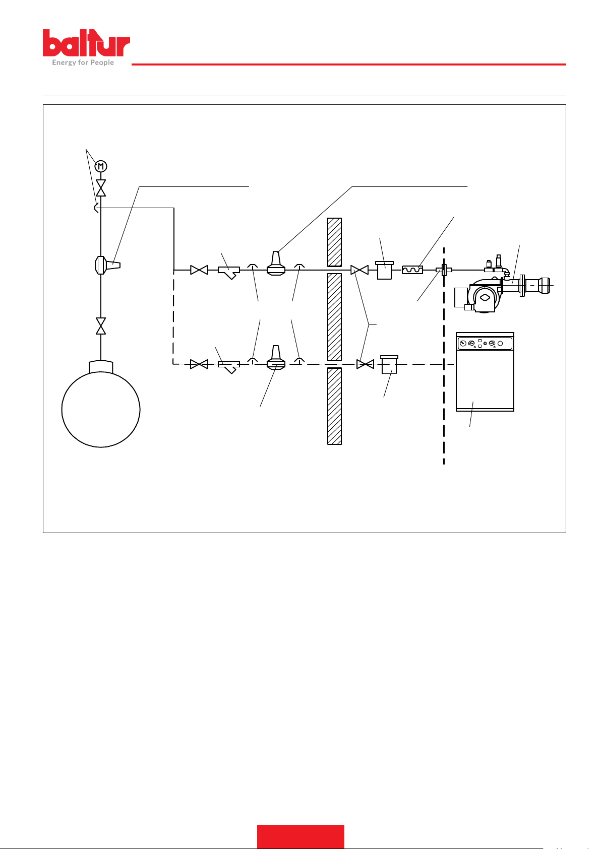
SCHEMA DI PRINCIPIO PER RIDUZIONE PRESSIONE G.P.L. A DUE STADI PER BRUCIATORE OPPURE CALDAIA
8721_2
Manometro e presa di pressione
ITALIANO
Serbatoio G.P.L.
Riduttore di 1° salto
Uscita ~ 1,5 bar
Portata ~ il doppio del massimo richiesto dall’utilizzatore
Filtro a Y
Presa di pressione
Filtro a Y
Riduttore di 2° salto
Uscita ~ 30 hPa (mbar)
Portata ~ il doppio del massimo richiesto
dall’utilizzatore
Riduttore di 2° salto
Uscita ~ 30 hPa (mbar)
Portata ~ il doppio del massimo richiesto dall’utilizzatore
Giunto antivibrante
Filtro
Raccordo
Rubinetto a
sfera
Filtro
Caldaia a pavimento o
Bruciatore
murale
A CURA DELL’INSTALLATORE
FORNITO DAL COSTRUTTORE
25 / 28
0006160053_201912
Page 28

ITALIANO
ISTRUZIONI PER L'ACCERTAMENTO DELLE CAUSE DI IRREGOLARITÀ NEL FUNZIONAMENTO E LA LORO ELIMINAZIONE
IRREGOLARITÁ
L'apparecchio va in "blocco" con
amma (lampada rossa accesa).
Guasto circoscritto al dispositivo di
controllo amma.
POSSIBILE CAUSA
1 Disturbo della corrente di ionizzazione da
parte del trasformatore di accensione.
2 Sensore amma (sonda ionizzazione)
inefciente.
3 Sensore di amma (sonda ionizzazione)
in posizione non corretta.
4 Sonda ionizzazione o relativo cavo a
massa.
5 Collegamento elettrico interrotto del
sensore di amma.
6 Tiraggio inefciente o percorso fumi ostru-
ito.
7 Disco amma o testa di combustione
sporchi o logori.
8 Apparecchiatura guasta.
9 Manca ionizzazione.
RIMEDIO
1 Invertire l'alimentazione (lato 230V) del
trasformatore di accensione e vericare con
micro-amperometro analogico.
2 Sostituire il sensore amma.
3 Correggere la posizione del sensore di amma
e, successivamente, vericarne l'efcienza
inserendo il micro-amperometro analogico.
4 Vericare visivamente e con strumento.
5 Ripristinare il collegamento.
6 Controllare che i passaggi fumo caldaia/rac-
cordo camino siano liberi.
7 Vericare visivamente ed eventualmente
sostituire.
8 Sostituirla.
9 Se la "massa" dell'apparecchiatura non è
efciente non si verica la corrente di ionizzazione.Vericare l'efcienza della "massa"
all'apposito morsetto dell'apparecchiatura e al
collegamento a "terra" dell'impianto elettrico.
L'apparecchio va in "blocco", il gas
esce, ma la amma non è presente
(lampada rossa accesa).Guasto circoscritto al circuito di accensione.
L'apparecchio va in "blocco", il gas
esce, ma la amma non è presente
(lampada rossa accesa).
1 Guasto nel circuito di accensione.
2 Cavetto trasformatore d'accensione scari-
ca massa.
3 Cavetto d'accensione scollegato.
4 Trasformatore d'accensione guasto.
5 La distanza tra l'elettrodo e massa non è
corretta.
6 Isolatore sporco e quindi l'elettrodo scari-
ca massa.
1 Rapporto aria/gas non corretto.
2 La tubazione del gas non è stata adegua-
tamente sfogata dall'aria (caso di prima
accensione).
3 La pressione del gas è insufciente o
eccessiva.
4 Passaggio aria tra disco e testa troppo
chiuso.
1 Vericare l'alimentazione del trasformatore
d'accensione (lato 230V) e circuito alta tensione (elettrodo a massa o isolatore rotto sotto il
morsetto di bloccaggio).
2 Sostituirlo.
3 Collegarlo.
4 Sostituirlo.
5 Metterlo alla corretta distanza.
6 Pulire o sostituire l'isolatore e l'elettrodo.
1 Correggere il rapporto aria/gas (probabilmente
c'è troppa aria o poco gas).
2 Sfogare ulteriormente, con le dovute cautele,
la tubazione del gas.
3 Vericare il valore della pressione gas al
momento dell'accensione (usare manometro
ad acqua, se possibile).
4 Adeguare l'apertura disco/testa.
26 / 28
0006160053_201912
Page 29
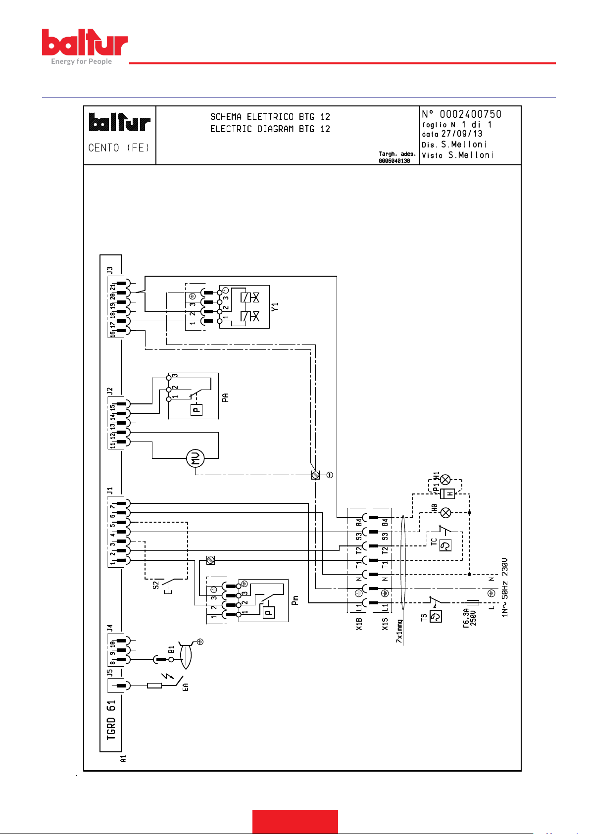
SCHEMI ELETTRICI
ITALIANO
27 / 28
0006160053_201912
Page 30

ITALIANO
A1 APPARECCHIATURA
B1 SENSORE FIAMMA
Y1/Y2 ELETTROVALVOLE 1° / 2° STADIO
H0 SPIA BLOCCO ESTERNA / LAMPADA FUNZIONAMENTO RESI-
STENZE AUSILIARIE
H1 SPIA DI FUNZIONAMENTO
P1 “CONTAORE“
PA PRESSOSTATO ARIA
Pm PRESSOSTATO DI MINIMA
MV MOTORE VENTOLA
S2 PULSANTE SBLOCCO
TC TERMOSTATO CALDAIA
TS TERMOSTATO DI SICUREZZA
X1B/S CONNETTORE ALIMENTAZIONE
L1 - L2- L3 Fasi
N - Neutro
Terra
Corrente ionizzazione minima 1,5 µA
28 / 28
0006160053_201912
Page 31

ENGLISH
ITALIAN
SUMMARY
Warnings for use in safety conditions .....................................................................................................................................................................2
Technical specications ..........................................................................................................................................................................................5
Standard accessories .......................................................................................................................................................................................6
Burner identication plate .................................................................................................................................................................................6
Data recorded during rst start-up ....................................................................................................................................................................6
Operating range ...............................................................................................................................................................................................7
Component description ....................................................................................................................................................................................7
Overall dimensions ...........................................................................................................................................................................................8
Electrical connections .............................................................................................................................................................................................9
Operating description ...........................................................................................................................................................................................10
“VPS 504” valve tightness control (if present) ................................................................................................................................................10
Natural gas ignition and regulation ....................................................................................................................................................................... 11
Ionisation current ............................................................................................................................................................................................13
Air regulation on the combustion head ...........................................................................................................................................................13
Diagram for regulating the combustion head and the electrode disk distance ...............................................................................................14
Control and command equipment TGRD 61 ........................................................................................................................................................15
Maintenance .........................................................................................................................................................................................................21
maintenance time ...........................................................................................................................................................................................22
Expected lifespan ...........................................................................................................................................................................................23
Specications for propane use .............................................................................................................................................................................24
Block diagram illustrating the principle of L.P.G. pressure reduction in two stages for burner or boiler .........................................................25
Instructions for determining the cause leading to irregularities in the operation and their elimination .................................................................26
Wiring diagrams ....................................................................................................................................................................................................27
1 / 28
0006160053_201912
Page 32

ENGLISH
WARNINGS FOR USE IN SAFETY CONDITIONS
PURPOSE OF THIS MANUAL
This manual is aimed at ensuring the safe use of the product to which it refers, through the indication of the necessary components in
order to prevent the original safety features from being jeopardized
by improper or erroneous installation and by improper, erroneous or
unreasonable use.
The manufacturer accepts no liability for any damage caused by
improper installation and use or in case of non-compliance with the
manufacturer's instructions.
• The manufactured machines have a minimum life of 10 years, if
normal working conditions are met and periodic maintenance spe-
cied by the manufacturer is done.
• The instruction booklet is an integral and essential part of the product and must be given to the user.
• The user must keep the booklet to hand for consultation when needed.
• Before starting to use the equipment, carefully read the "In-
structions for use" in this manual and those directly applied to
the product in order to minimize risks and accidents.
• Observe the SAFETY WARNINGS, avoid IMPROPER USES.
• Installer must evaluate any RESIDUAL RISK that might arise.
• This manual contains symbols to highlight some parts of the text or
to indicate some important specications. You nd their description
below.
DANGER / ATTENTION
This symbol indicates a very dangerous situation that, if ignored, can seriously endanger people health and safety.
CAUTION / WARNINGS
This symbol indicates that it is necessary to behave properly
to void endangering people's health and safety and causing
economical damages.
ment use.
• Children must be watched over to prevent them from playing with
the equipment.
• This appliance should only be used for the purpose it has been
designed for. Any other use is to be considered improper and therefore dangerous.
• The equipment must be installed in accordance with current regulations, with the manufacturer’s instructions and by qualied technicians.
• The term ‘qualied personnel’ refers to those specically trained
in the eld and with proven skills, in accordance with the local law
in force.
• An incorrect installation can cause injury or damage to persons,
animals and objects, for which the manufacturer cannot be held
responsible.
• After removing all the packaging make sure the contents are com-
plete and intact. If in doubt, do not use the equipment and contact
your supplier. The packing pieces are potentially dangerous and
must be kept away from children.
• The majority of the equipment components and its package is
made with reusable materials. The package, the equipment and
its components cannot be disposed of with the standard waste but
according to the regulations in force.
• Before carrying out any cleaning or maintenance, disconnect the
equipment at the mains supply, using the system’s switch and/or
shut-off systems.
• If the equipment is sold or transferred to another owner or if the ow-
ner moves and leaves the equipment, make sure that the booklet
always goes with the equipment so it can be consulted by the new
owner and/or installer.
• When the equipment is working, do not touch hot parts that are
usually positioned near the ame and the fuel pre-heating system,
if any. They could still be hot after the equipment is turned off for a
short period of time.
IMPORTANT
This symbol indicates particularly important technical and operative information that must not be neglected.
CONDITIONS AND DURATION OF STORAGE
The equipment is shipped with the manufacturer package and tran-
sported on road, by boat or by train in compliance with the standards
on goods transport in force for the actual mean of transport used.
The unused equipment must be placed in closed rooms with enough
air circulation in standard conditions with temperature between -25°
C and + 55° C.
The storage time is 3 years.
GENERAL WARNINGS
• The equipment production date (month, year) is written on the burner identication plate located on the equipment.
• The equipment cannot be used by people (including children) with
reduced physical, sensory or mental capacities or lacking experien-
ce or know-how.
• The equipment use is allowed to such people only if they can have
access to, through a responsible person, the information concerning their safety, surveillance and instructions concerning equip-
0006160053_201912
2 / 28
Page 33

ENGLISH
• If there is any fault or if the equipment is not working properly,
de-activate the equipment and do not attempt to repair it or tamper
with it directly. Contact only qualied personnel.
• Any product repairs must only be carried out by BALTUR authori-
sed assistance centres or by its local distributor using only original
spare parts.
• The manufacturer and/or its local distributor are not liable for any
accident or damage caused by unauthorised changes of the product and by failure to follow the rules described in the manual.
SAFETY WARNINGS FOR INSTALLATION
• The equipment must be installed in a well-ventilated suitable room
in compliance with the laws and regulations in force.
• Ventilation grille section and installation room aeration openings
must not be obstructed or reduced.
• The installation room must NOT have the risk of explosion and/
or re.
• Before installing the equipment we recommend to carefully clean
the interior area of all fuel supply system pipes.
• Before connecting the equipment check that the details on the plate
correspond to those of the utility supplies (electricity, gas, light oil
or other fuel).
• Make sure the burner is rmly xed to heat generator according to
manufacturer instructions.
• Connect to the source of energy according to state-of-the-art stan-
dards as described in the explanatory diagrams and in compliance
with the regulatory and law requirements in force at the moment of
installation.
• Check that the fume disposal system is NOT obstructed.
• If it is decided not to use the burner any more, the following proce-
dures must be performed by qualied technicians:
- Switch off the electrical supply by disconnecting the power
cable from the main switch.
- Cut off the fuel supply using the shut-off valve and remove the
control wheels from their position.
- Render harmless any potentially dangerous parts.
- Check the efciency of the combustion products exhaust duct.
- Check seal in the fuel supply pipe internal and external section.
- At the end of the adjustment procedures, check that all the
locking devices of mechanical securing systems are properly
tightened.
- Make sure that the use and maintenance manual of the burner
is available.
• If the burner repeatedly stops in lock-out, do not keep trying to manually reset it but call a qualied technician.
• If you decide not to use the burner for a while, close the valve or
valves that supply the fuel.
WARNINGS FOR START UP, TEST, USE AND MAINTENANCE
• Start up, test and maintenance of the equipment must only be carried out by qualied technicians, in compliance with current regu-
lations.
• Once the burner is xed to the heat generator, make sure that the
generated ame does not come out of any slot during testing.
• Check equipment fuel supply pipe seal.
• Check that fuel ow rate equals the power required to the burner.
• Set the burner fuel capacity to the power required by the heat generator.
• Fuel supply pressure must be within the values indicated on the
plate on the burner and/or manual
• The fuel supply system is suitably sized for the ow required by the
burner and that it has all the safety and control devices required by
current standards.
• Before starting up the burner, and at least once a year, have quali-
ed technicians perform the following operations:
- Set the burner fuel capacity to the power required by the heat
generator.
- Check combustion and adjust combustion and/or fuel air ow to
optimize combustion and reduce emissions in accordance with
the law in force.
- Check the adjustment and safety devices are working properly.
0006160053_201912
3 / 28
Page 34

ENGLISH
Special precautions when using gas.
• Check that the feed line and the train comply with current law and
regulations.
• Check that all the gas connections are properly sealed.
• Do not leave the equipment on when it is not in use and always
close the gas cock.
• If the user is absent for a prolonged period of time, close the main
gas feed tap to the burner.
• If you smell gas:
- do not operate electrical switches, phones or any other object
that may cause sparks;
- open immediately doors and windows to create a draught to
clear the air in the room;
- close the gas cocks;
- have professionally qualied personnel correct the fault.
• Do not obstruct ventilation openings in the room where there is
gas equipment. Otherwise, dangerous situations may arise with the
build up of toxic and explosive mixtures.
RESIDUAL RISKS
• Even though the product was designed in compliance with the obligatory standards, residual risks may still be present during correct
operation. They are signalled on the burner through special Picto-
grams.
CAUTION
Moving mechanical organs.
etc.).
• Use regulation-compliant exible cables EN60335-1:EN 60204-1
- in case of PVC sheath, at least type H05VV-F;
- in case of rubber sheath, at least type H05RR-F; LiYCY
450/750V
- without any sheath, at least type FG7 o FROR, FG70H2R
• The electric equipment works correctly when the relative humidity
does not exceed the 50% at a maximum temperature of +40° C.
Higher relative humidity are allowed at lower temperatures(e.g. 90
% at 20° C)
• The electric equipment works correctly at altitudes of up to 1000 m
above the see level.
DECLARATION OF CONFORMITY
IMPORTANT
We hereby declare that our gas, liquid and mixed forced draught burners respect the minimum requirements of the Europe-
an Directives and Regulations and are compliant with European standards.
A copy of the EC declaration of conformity is supplied with the
burner.
CAUTION
Materials at high temperature.
CAUTION
Powered electric panel.
ELECTRIC SAFETY WARNINGS
• Check that the equipment has a suitable ground system, carried
out following safety standards in force.
• Have qualied personnel check that the electric system is adequate
to equipment maximum power consumption indicated on the plate.
• For the mains supply connection is required an omnipolar switch
with a contact opening gap equal or above 3 mm in accordance
with current safety regulations (condition of overvoltage category
III).
• Remove the external insulating seal of the supply pipe necessary
for the connection, preventing the cable to touch metal parts.
• The use of any electrically fed components entails complying with
certain fundamental rules, including the following:
- do not touch the equipment with parts of the body that are wet
or damp or with damp feet;
- do not pull on electrical cables;
- do not leave the equipment exposed to atmospheric agents
(such as rain or sun etc.) unless there is explicit provision for
this;
- do not allow the equipment to be used by children or inexpert
persons;
- The power supply cable for the equipment must not be replaced
by the user. In case of cable damage, turn the equipment off. To
replace it contact qualied personnel only;
- If you decide not to use the equipment for a certain period of
time it is advisable to switch off the electrical power supply to all
components in the system that use electricity (pumps, burner,
4 / 28
0006160053_201912
Page 35

TECHNICAL SPECIFICATIONS
MODEL BTG 12
Type-approval PIN CE0085BQ0476
Maximum natural gas heat power
Minimum natural gas heat power
¹) natural gas emissions
Operation
50 Hz natural gas transformer
Maximum natural gas heat rate
Minimum natural gas heat rate
Maximum natural gas pressure
Minimum natural gas pressure
Maximum propane thermal power
Minimum propane thermal power
Maximum propane thermal ow rate
Minimum propane thermal ow rate
Maximum propane pressure
Minimum propane pressure
²)propane emissions
50hz fan motor
50hz fan motor rpm
Absorbed electrical power* 50hz
50 Hz power supply voltage
Protection rating
Flame detection
Control box
Operating ambient air temperature
Sound pressure**
Weight with packaging
Weight without packaging
kW
kW
mg/kWh
Stm³/h
Stm³/h
hPa (mbar)
hPa (mbar)
kW
kW
Stm³/h
Stm³/h
hPa (mbar)
hPa (mbar)
mg/kWh
kW
r.p.m.
kW
°C
dBA
kg
kg
BRAHMA KOMPACT TGRD61
115
35
Class 2
single-stage
17 kV - 60 mA
11.88
3.6
360
16.6
115
35
4.7
1.43
200
14.6
Class 3
0.11
2800
0.2
1N~ 230V ± 10%
IP 20
IONISATION PROBE
-15 ÷ +40
60
12
10.75
ENGLISH
Caloric power below reference conditions 15° C, 1013 hPa (mbar):
Natural gas: Hi = 9,45 kWh/Stm³ = 34,02 MJ/Stm³
Propane: Hi = 24,44 kWh/Stm³ = 88,00 MJ/Stm³
For different types of gases and pressure values, contact our sales departments.
* Total absorption at start-up with ignition transformer on.
The measurements have been carried out in accordance with EN 15036 - 1 standard.
** The acoustic pressure measured with burner operating at maximum rated thermal output refers to the manufacturer's laboratory environment
conditions and cannot be compared to measurements carried out in different locations.
Propane / natural gas CO emissions ≤ 100 mg/kWh
¹) NATURAL GAS EMISSIONS
Classes dened according to EN 676 standards.
Class
1 ≤ 170
2 ≤ 120
3 ≤ 80
NOx emissions in mg/kWh natural
gas
²) PROPANE GAS EMISSIONS
Classes dened according to EN 676 standards.
Class
1 ≤ 230
2 ≤ 180
3 ≤ 140
NOx emissions in mg/kWh propane
gas
5 / 28
0006160053_201912
Page 36
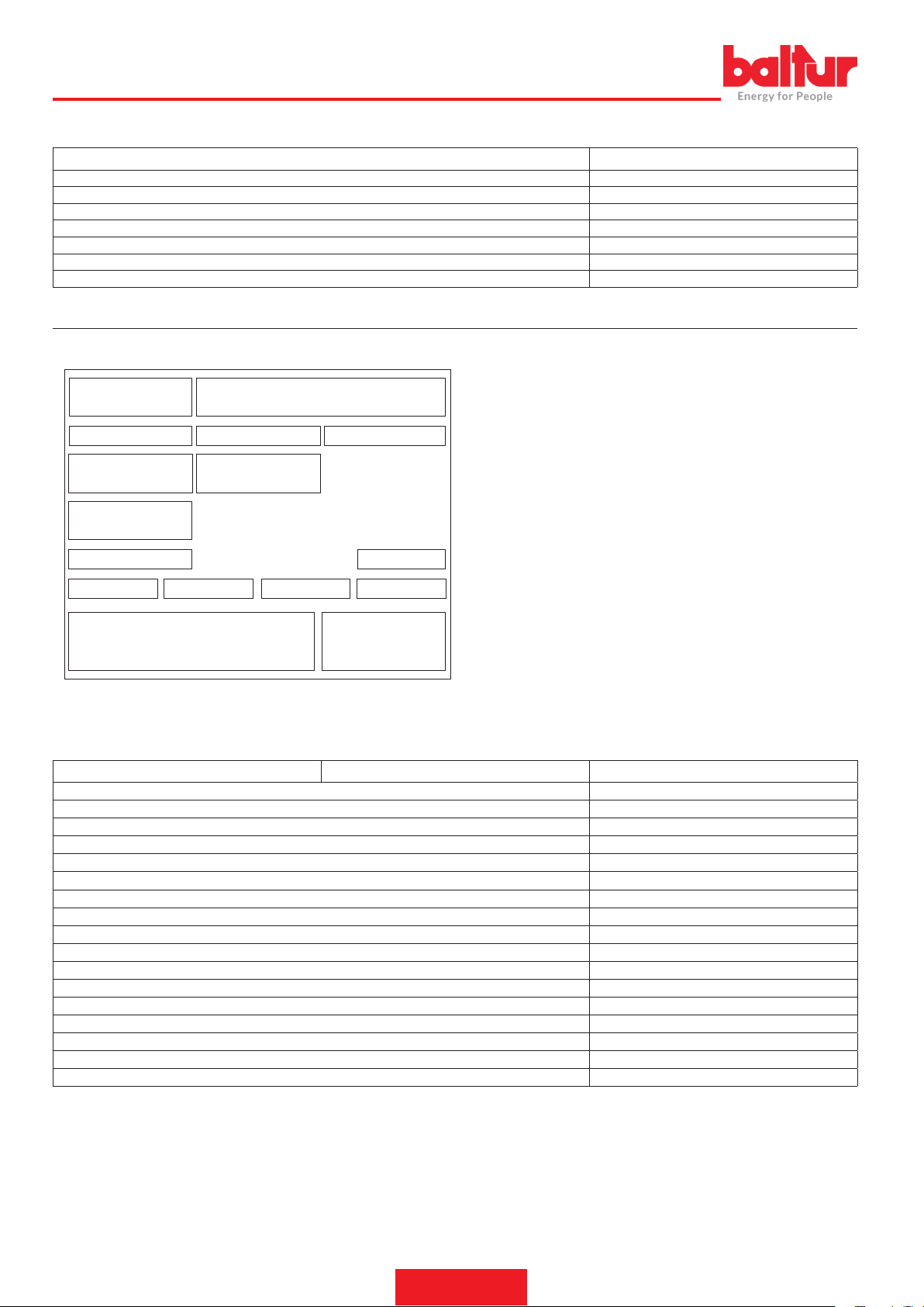
Targa_descr_bru
ENGLISH
STANDARD ACCESSORIES
MODEL BTG 12
Burner connection ange 1
Burner coupling ange gasket 1
Stud bolts N°4 M8 x 37
Hexagon nuts No.5 M8
Flat washers No.4 Ø 8
Screw N°1 M8 x 25
7-pole connector 1
BURNER IDENTIFICATION PLATE
1 Company logo
2 Company name
1 2
3 4 5
6 7
8
9
10 13
11
12
14
1615
3 Product code
4 Burner model
5 Serial number
6 Liquid fuel power
7 Gaseous fuel power
8 Gaseous fuel pressure
9 Liquid fuel viscosity
10 Fan motor power
11 Power supply voltage
12 Protection rating
13 Country of origin and numbers of certicate of approval
14 Manufacturing date - month / year
15 -
16 Bar code serial number of burner
DATA RECORDED DURING FIRST START-UP
Model: Date: Time:
Type of gas
Lower Wobbe index
Lower caloric power
Min. gas ow rate
Max. gas ow rate
Min. gas power
Max. gas power
System gas pressure
Gas pressure downstream from stabilizer
CO (at minimum power)
CO2 (at minimum power)
Nox (at minimum power)
CO (at maximum power)
CO2 (at maximum power)
Nox (at maximum power)
smoke temperature
air temperature
Stm³/h
Stm³/h
kW
kW
hPa (mbar)
hPa (mbar)
ppm
%
ppm
ppm
%
ppm
6 / 28
0006160053_201912
Page 37
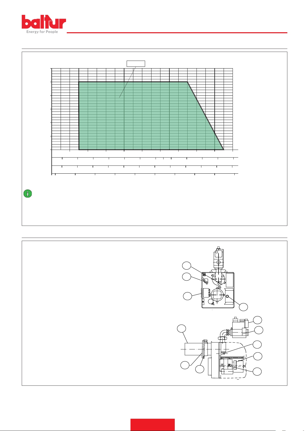
OPERATING RANGE
1,5
2
2,5
3
3,5
4
4,5
1
5
5.5
ENGLISH
2.5
1.5
0.5
mbar
3
2
1
0
30 40 50
30
40 50 60 70 80 90
3
4 5 6 7 8 9 10 11
BTG 12
60 70 80 90
100 110
100
110
120
12 13 14
130
0002922950
kcal/hx1.000
120
kW
140
mn³/h(metano)
mn³/h(G.P.L)
IMPORTANT
The operating ranges are obtained from test boilers corresponding to Standard EN676 and are indicative of the burner-boiler combination. For correct working of the burner, the size of the combustion chamber must correspond to current regulations; if not the manufacturers must be consulted.
The burner shall not operate outside its specic operating range.
COMPONENT DESCRIPTION
1 Reference for disk - head positioning
2 Screw for adjusting air damper opening
3 7-pole connector
4 Control box
5 Combustion head
6 Insulating gasket
7 Burner connection ange
8 Motor
9 Air pressure switch
10 Head disk adjusting screw
11 Gas valve monoblock
12 Minimum gas pressure switch
0002471470nom
1
2
3
4
12
5
11
10
9
6
7
8
7 / 28
0006160053_201912
Page 38
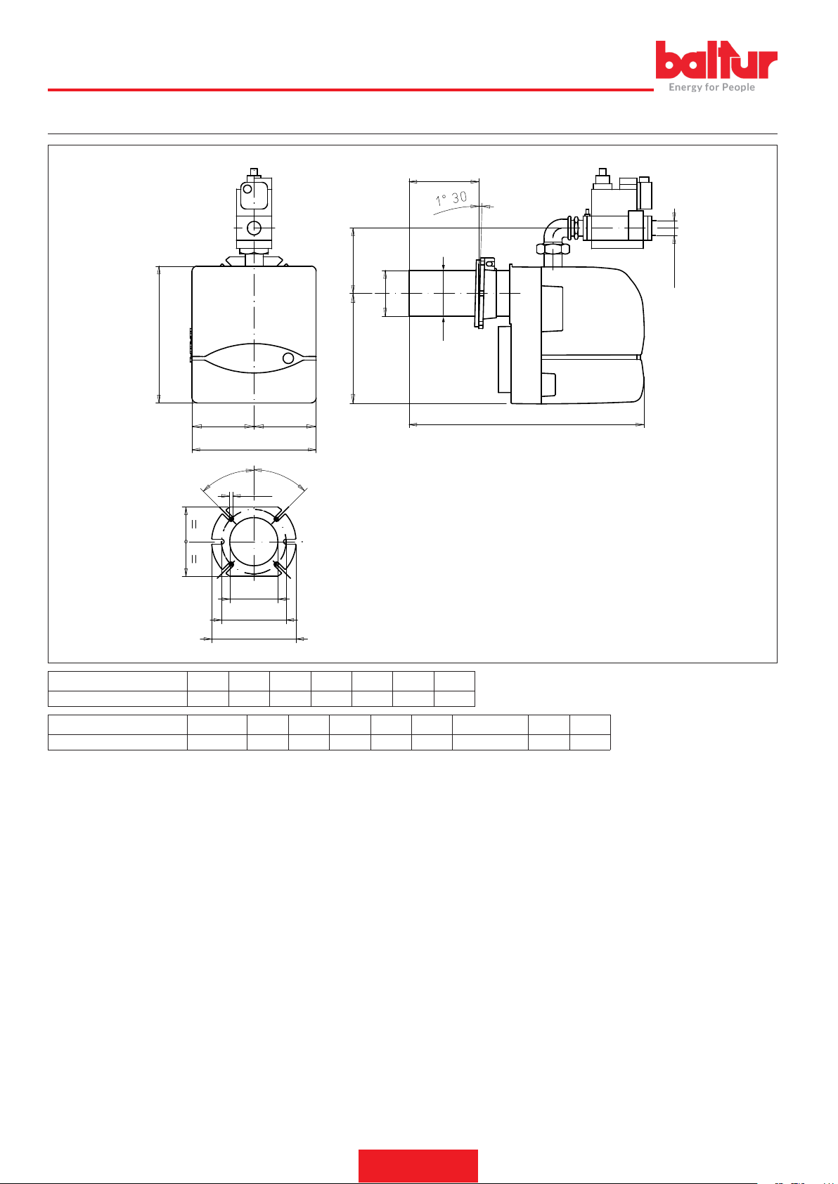
ENGLISH
OVERALL DIMENSIONS
D
B6
EØ
B
B1
A1
45°
I1
A2
A
45°
M
N
L
I
FØ
C
G
0002471470dim
Model A A1 B B1 B2 B6 C
BTG 12 246 123 289 219 70 53 450
Model D E Ø F Ø G I I1 LØ M N Ø
BTG 12 70 ÷ 150 90 90 Rp 3/4 170 140 130 ÷ 155 M8 95
8 / 28
0006160053_201912
Page 39

ELECTRICAL CONNECTIONS
• Observe applicable national and European Standards (e.g. EN
60335-1/EN 50165) regarding electrical safety.
• Connect the devices, without option N or N1, to the power supply
respecting the phase-neutral polarity of the mains.
• Gas models, with detection electrode, are equipped with a device
that recognises the polarity.
• Failure to respect the phase-neutral polarity causes a non volatile
lock out at the end of the safety time. In the event of a 'partial' short
circuit or poor isolation between the line and earth, the voltage on
the detection electrode may be reduced until it causes the equipment to lock out, given that the ame signal fails to be detected.
• Carefully check the cables before commissioning.
• Incorrect wiring can damage the equipment and jeopardise system
safety.
• Makes sure the equipment earth terminal, the metal burner casing
and electrical system earthing are connected properly.
• Avoid laying the detection cable along with the power cables or
ignition cables.
• Use a cable and detection electrode capable of withstanding heat.
They should also be well insulated and protected against conden-
sation or water in general;
• Use a shorter and straight ignition cable and lay it far from other
conductors to minimise radio interferences, (maximum length less
than 2 m and insulating voltage > 25 kV);
• This equipment has internal fuses, however, it must be protected
by means of at least one fuse on the line connection.
The electric motor is equipped with an automatic reset thermal cutout that causes it to stop when overheating.
ENGLISH
CAUTION / WARNINGS
If it stops please make sure that the motor is in good conditions
and verify the causes of its overheating.
9 / 28
0006160053_201912
Page 40
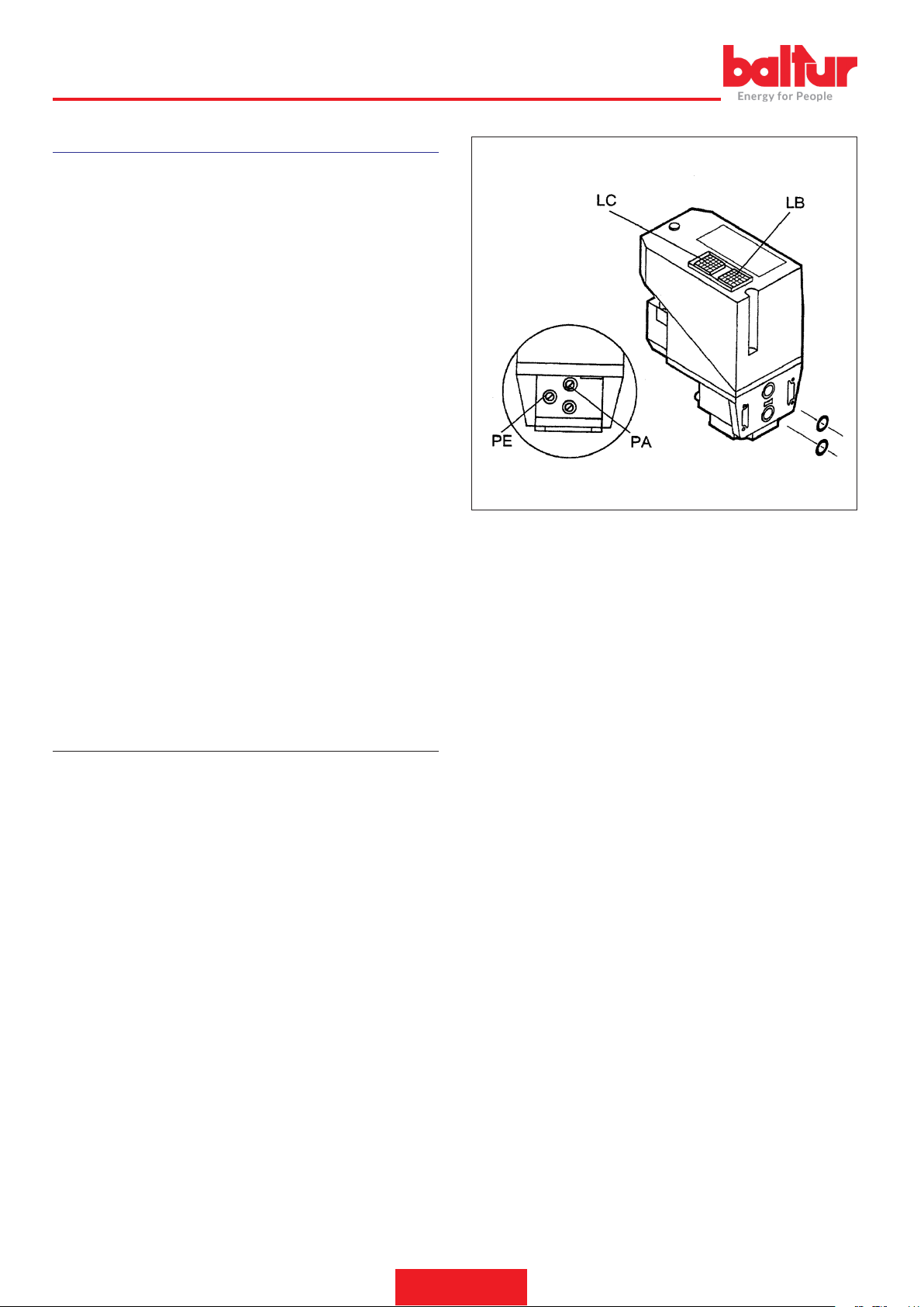
ENGLISH
OPERATING DESCRIPTION
Installation instructions:
• Ignition devices are safety devices. Their tampering voids the war-
ranty and releases the manufacturer from any liability.
• The system is designed to stay fully operational for less than 24
hours (non-permanent system).
• As this threshold is reached, a regulation stop is triggered to allow
the equipment to verify its efciency.
• Connect and disconnect the equipment only when voltage is off.
• Before installing or replacing the equipment, make sure the type,
time interval and code are those foreseen.
• The system in which the devices are installed, must provide an
adequate protection against electrocution risks (at least IP20).
• The remote reset button must be installed close to the system, to
allow it to be clearly visible during the reset.
The burner operates fully automatically: it is activated by switching on
the main switch and the control panel switch.
If when the main switch is turned on, the thermostats are on, the
voltage reaches the control box which starts the burner.
This turns on the fan motor for pre-ventilating the combustion chamber.
The ignition transformer then comes on, and 2 seconds later the gas
valves open.
The presence of the ame, detected by the control device, permits
continuation and completion of ignition, turning off the ignition transformer.
If there is no ame, the appliance goes to “safety lock-out” mode within 3 seconds of the opening of the rst ame on the main valve.
In “safety lock-out” mode the valves are closed again immediately.
To reset the equipment from its safety position, press the red button
on the equipment.
“VPS 504” VALVE TIGHTNESS CONTROL (IF PRESENT)
It checks the tightness of gas cut-off valves.
This check is carried out as soon as the boiler thermostat authorises
burner operation creating, by means of a membrane pump, an overpressure greater than the upstream pressure by 20 mbar in the test
circuit.
If you wish to carry out a check, place a pressure gauge corresponding to the PA pressure plug.
If the test circuit has a positive result, the LC authorisation lamp (yellow) switches on after a few seconds.
In order to restart, it is necessary to unlock the equipment using the
LB light button.
The fuse can be accessed using a screwdriver to remove the cover
that is located near the sockets for electrical connection; a spare fuse
is located in the upper part of the tightness control, under the cap.
10 / 28
0006160053_201912
Page 41
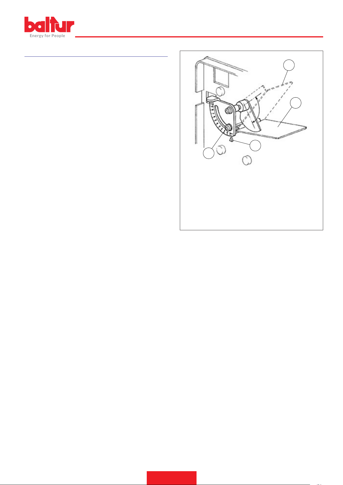
NATURAL GAS IGNITION AND REGULATION
8922/2
ENGLISH
Carry out a check of the equipment before commissioning, after each
overhaul and after the equipment has been inactive for a long time.
Verify the combustion chamber does not contain gas before any igni-
tion operation.
• Attempting a start up without introducing gas, verify a lock out stop
occurs at the end of the safety time (or more cycle repetitions up to
a maximum of 10, depending on the settings).
• Interrupting the ow of gas with the equipment operating, verify that
voltage to the gas solenoid valves is cut within 1 sec., and after a
cycle repetition (or more repetitions up to a maximum of 10, depending on the settings), the equipment carries out a lock out stop.
• The time and cycle comply with those indicated for the type of equi-
pment used.
• The ame signal level is sufciently high.
• The ignition electrodes are regulated according to an air discharge
distance between 2 and 4 mm.
• The intervention of limiters or safety devices causes a shut down
or safety stop of the equipment according to the type of application
and modes foreseen.
• Make sure that the combustion products may be freely vented
through the boiler and ue dampers.
• Make sure that the mains voltage corresponds to the manufactu-
rer's requirements and that all electrical connections made at the
installation site are effected properly as illustrated in our wiring diagram.
• Check that there is water in the boiler and that the gate valves of
the system are open.
• Open the combustion air regulator as necessary and open approx.
a third of the passage of air between ame disk and head (diffuser). Act on the regulators incorporated in the safety and operating
valve in such a way as to obtain the gas delivery deemed to be
necessary.
• Power the burner by connecting the main switch.
• The burner is therefore activated and carries out the pre-ventilation
phase.
• If the air pressure exceeds that value at which the air pressure
switch has been set, the ignition transformer will be connected and,
subsequently, the gas valves (safety and operating) will be inser-
ted.
• The valves open completely and the gas delivery is limited to the
position at which the ow regulator incorporated in the main operating valve has been manually regulated.
4
3
2
1
1 Screw for adjusting air damper opening
2 Air damper opening reference index
3 Closed damper: reference index in position “0”
4 Damper fully open: reference index in position “0”
• Upon rst switching on, repeated “lock outs” may occur due to:
• The gas pipeline has not been adequately purged of air and there-
fore the quantity of gas is not sufcient to allow for a stable ame.
• “Lock out” with ame presence could be caused by ame instability
in the ionisation area, due to an incorrect air/gas ratio.
• This can be solved by changing the amount of air and/or gas sup-
plied, so as to nd the right ratio.
• This problem could also be caused by an incorrect distribution of
air/gas in the combustion head.
• This can be solved with the combustion head adjustment device by
further closing or opening the air passage between the combustion
head and gas diffuser, through the ame disk adjustment system.
• It may occur that the ionisation current is disturbed by the discharge current of the ignition transformer (the two currents have a com-
mon path on the burner’s “mass”). Therefore, the burner locks out
due to an insufcient ionisation.
• This can be solved by verifying the correct position of the ignition
electrode.
• A shut down with ame presence could also be caused by the bur-
ner’s casing not being properly “grounded”.
• The minimum ionisation current value required for a correct operation of the equipment is indicated in the wiring diagram.
11 / 28
0006160053_201912
Page 42
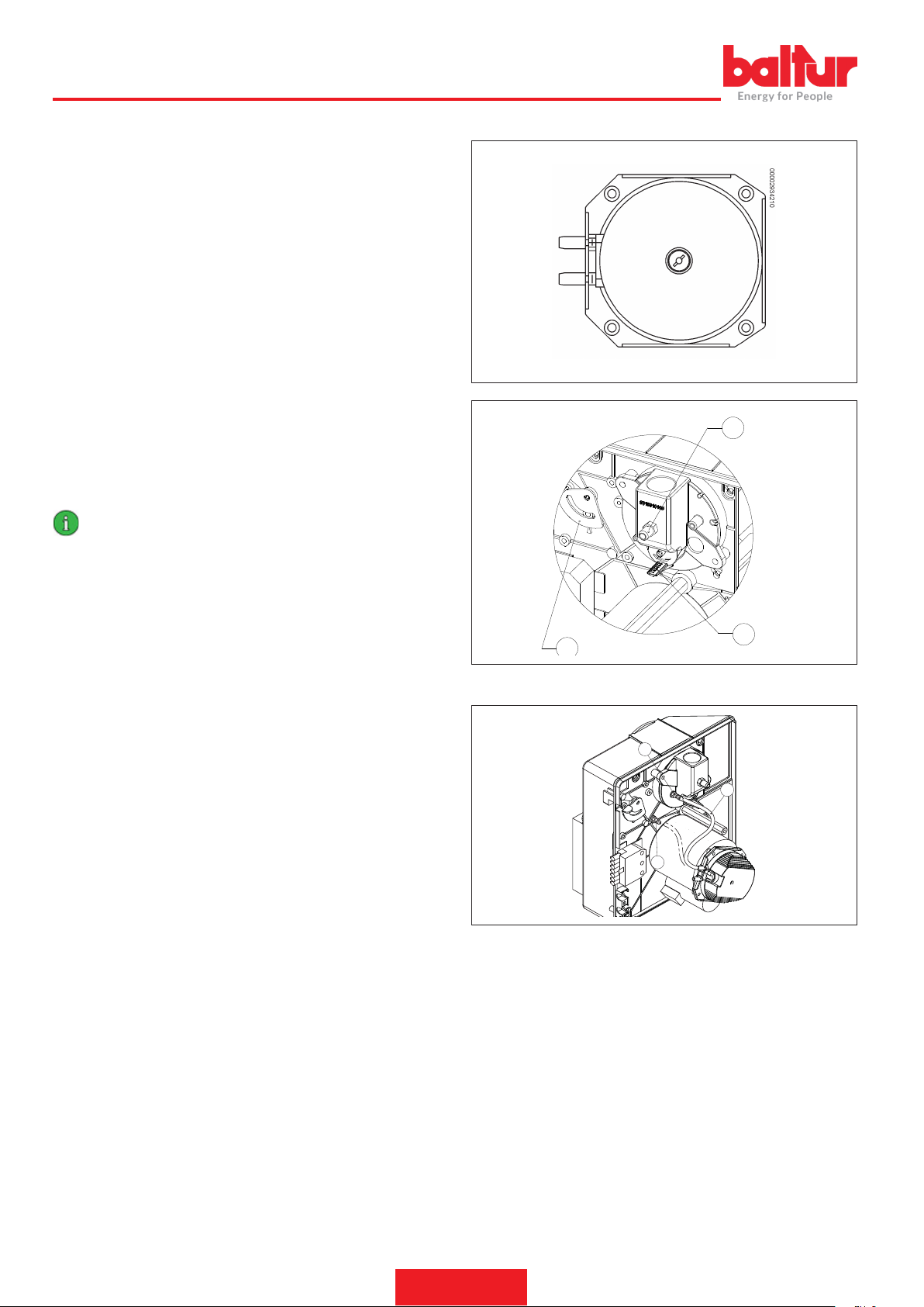
3
0002939070
ENGLISH
• With the burner on, adapt ow rate to the required value, by reading
the meter.
• The ow rate can be modied using the special regulator incorpora-
ted on the valve (see the following pages for a description on how
to regulate the valves).
• Check that combustion occurs correctly by using the appropriate
instruments (CO2 max= about 10% for natural gas - CO max. =
0.1%).
• After this adjustment, switch the burner off and on again a few times to check if ignition is correct.
• When the burner is lit, it is necessary to check as previously shown,
the gas ow and the combustion with the appropriate instruments.
When the results are known, if necessary proceed with varying the
gas delivery and relative combustion air in order to adapt delivery
to that required for the specic case (boiler potentiality). It’s also
necessary to check if the CO2 and CO values are adequate (CO-
2max. = about 10% for natural gas and CO = 0.1%).
• Control the efciency of the safety and “shut down” devices (by
disconnecting the ionisation electrode cable), air pressure switch,
gas pressure switch and thermostats.
IMPORTANT
The pressure switch connection circuit is self-controlling. The-
refore, the contact which is meant to be closed in a non-operating state (fan stopped and thus no air pressure in burner),
should in fact be in this state, otherwise the command/control
equipment will not be switched on (burner remains inoperative).
• Make sure that the combustion products may be freely vented
through the boiler and ue dampers.
• If the contact foreseen to close when the unit is operating does not
close, the unit performs its cycle but the ignition transformer does
not start and the gas valves do not open, hence the burner remains
locked out.
• Check that the air pressure switch functions properly with burner
operating at 1st ame only, increase the regulating value until it
reaches intervention point and the burner should go to shut down.
• To unblock the burner, press the special pushbutton and return the
pressure switch regulator to a sufcient value in order to measure
the air pressure existing during the pre-ventilation phase.
AIR PRESSURE SWITCH
Regulate the air pressure switch after rst carrying out all the other
burner adjustments with the air pressure switch adjusted to the start
of the scale.
With the burner operating at the required power, slowly turn the central screw clockwise until the burner locks out.
Then give the screw a half-turn anti-clockwise and repeat burner
start-up to check for proper operation.
If the burner locks out again give the screw another half-turn.
The air pressure switch stops the equipment operation if air pressure
is not at the expected value.
If the air pressure switch does not detect a pressure greater than that
calibrated, the equipment runs through its cycle but does not switch
on the ignition transformer and does not open the gas valves and so
the burner “locks-out”.
1
2
BURNER INSTALLATION ON INDUSTRIAL SYSTEMS
A
B
0002939510
C
If the air pressure switch measures a value less than the minimum
calibration value, remove the tube "C” from the pressure port "A” and
connect it to pressure port "B”.
At the end repeat again the air pressure switch adjustment.
12 / 28
0006160053_201912
Page 43
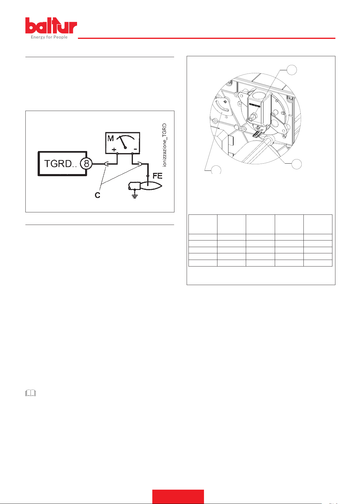
IONISATION CURRENT
3
0002939070
The maximum ionisation current value required for a correct operation of the equipment is indicated in the wiring diagram.
The burner provides a signicantly higher current and therefore does
not normally require any checks at all.
To measure the ionisation current connect a microammeter in series
to the ionisation electrode cable by opening the connector “C” as
shown in the gure.
ENGLISH
1
2
1 - Pressure port P3
2 - Mixer disk position index
3 - Damper index
POWER ADJUSTMENT INDICATIVE DATA
AIR REGULATION ON THE COMBUSTION HEAD
The combustion head is equipped with a regulation device that makes
it possible to open or close the air passage between the disk and
the head. Closing the passage increases the pressure upstream of
the disk also with low ow rates. The high speed and turbulence of
the air provides for its greater penetration into the fuel and therefore
an excellent mixture and ame stability. High air pressure upstream
of the disk may be necessary to prevent ame uctuations, this is
particularly essential when the burner works on the furnace that is
pressurised and/or at a high thermal load.
The combustion head closing device must be set to a position in which, behind the disc, there is always a very high air pressure value.
When the burner operates at maximum delivery, adjust the head air
closure, in such a way as to require a considerable air ow damper
opening. Therefore start the regulation with the device that closes
the air on the combustion head in an intermediate position, igniting
the burner for an indicative regulation as explained above. Move the
combustion head forward or backward so as to have an air ow suitable for the delivery.
When the |b|maximum required supply|bb| is reached, correct the
position of the device closing the air on the combustion head by moving it forwards or backwards so as to have a suitable air ow for the
supply, |b|with suction air adjustment damper considerably open.|bb|
CAUTION / WARNINGS
Check that ignition takes place regularly, by acting gradually on
the disk-head adjusting screw, until you reach a position in whi-
ch ignition occurs regularly. For the rst stage, limit the quantity
of air to that which is strictly necessary for safe ignition, even in
the most difcult circumstances.
Power kW
35 2 2 1.8 1.5
55 3 3 2.2 1.8
75 4,5 4.5 2.9 2.2
95 6 6 4.3 3.2
115 9 9 5.5 1.3
Air damper
position
Mixer disk
position
Natural gas
mbar pressu-
re P3
LPG mbar
pressure P3
13 / 28
0006160053_201912
Page 44
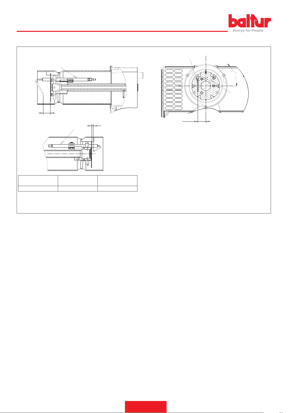
ENGLISH
DIAGRAM FOR REGULATING THE COMBUSTION HEAD AND THE ELECTRODE DISK DISTANCE
7
7
A
21.5
A
8
0002939080
45
8
A 20 mm 4-5 mm
Ionisation electrode
pos. 7
Ignition electrode
pos. 8
14 / 28
0006160053_201912
Page 45

ENGLISH
CONTROL AND COMMAND EQUIPMENT TGRD 61
The following description refers to the control devices with a standard working cycle. The device carries out a self-test of its efciency upon each
start up.
During the waiting time (TW) or pre-ventilation time (TP) the internal circuit controls the correct operation of the ame signal amplier: A parasitic
ame signal or a failure of the amplier which corresponds to the current ame conditions prevent the equipment from starting up.
On models tted with a fan control, it is veried that the air pressure switch contact is in the air absence position before the start of the pre-ventilation time (TP). Only if this verication has a positive outcome, the switching of the pressure switch allows the start of the pre-ventilation (TP)
stage.
The verication of the air pressure switch contacts is performed at the beginning of each cycle.
At the end of the waiting time (TW) or pre-ventilation time (TP), the gas solenoid valve EV1 is powered and the ignition device started, thus
allowing the safety time (TS) to begin.
If the equipment detects a ame signal during the safety time, the ignition device is inhibited and, in some models, the main valve EV2 is powered.
Instead, if the equipment does not detect any ame signal during the safety time, a lock out stop occurs at the end of the safety time. This closes
the solenoid valves, inhibits the ignition device and provides the lock out signal.
To better understand the operation of the individual equipment, see the cycle diagrams,
MALFUNCTION AND LOCK CAUSE DIAGNOSTICS.
In the event of a lock out, pressing the reset button for more than 5 sec, activates diagnostics (alarm signal ashing).
The alarm signal is switched off for a number of times depending on the type of lock out with a pause of 2 seconds between a series of ashes
and the next.
The table below indicates the meaning of the lock out or malfunction cause according to the number of ashes.
Error code table
Code for ashing alarm signal (red LED) Possible causes
2 blinks
●●
3 blinks
●●●
4 blinks
●●●●
5 blinks
●●●●●
6 blinks
●●●●●●
7 blinks
●●●●●●●
8 - 14 blinks Generic internal fault.
No ame signal at the end of the safety time <TS>
- Fuel valves malfunctioning
- Flame detector malfunctioning
- Incorrect burner calibration, no fuel
- No ignition faulty ignition transformer
Air pressure switch does not close or the revolutions per minute are lower than the minimum set-
ting (TGRD6x-TGRD8x). Pre-heat thermostat does not close (TGRD7x-TGRD9x). Safety thermostat does not close (TGRDxx).
Extraneous light during the ignition phase
Air pressure switch does not open or the revolutions per minute are higher than the minimum
setting (TGR6x-TGR8x).
Air pressure switch loss or the revolutions per minute, in operation, are lower than the minimum
setting (TGRD6x-TGRD8x). Safety Thermostat loss in operation (TGRDxx).
Lack of ame in operation
15 / 28
0006160053_201912
Page 46
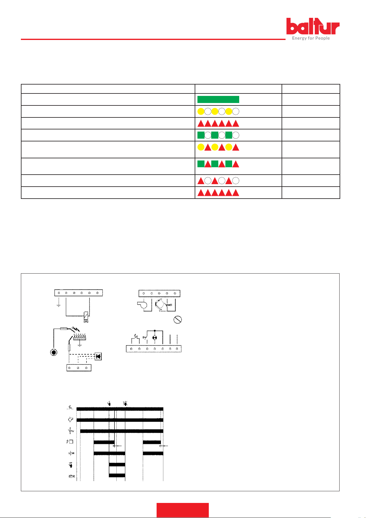
ENGLISH
SIGNALLING DURING OPERATION
The equipment is capable of indicating the operation status in various operating conditions by means of a multi-colour LED positioned near the
lock out signal.
A key of the colours is shown below:
Condition Colour sequence Colours
Good operating mode with good ame signal Green
Ignition phase Orange
Burner shut down condition Red
Operating mode with scarce ame signal Intermittent green
Low/high voltage signal Alternating red and
orange
Ignition mode with scarce ame signal Alternating green and
orange
Ignition status with good ame signal Flashing orange
Diagnostics of the lock-out mode or parasitic ame Intermittent red
On request, it is possible to vary the operating mode signalling of the multi-colour LED.
RESETTING THE EQUIPMENT
Non-volatile lock-out (manual reset)
When the equipment goes into a non-volatile lock-out condition, to reset the system it is necessary to hold down the reset button until the lock-out
signal switches off (< 5 seconds).
Volatile lock-out (electric reset)
The equipment can be reset from a volatile lock out by interrupting and then restoring the power supply. The system cannot be reset by switching
off the heat request device.
CONNECTION DIAGRAM
EVP Pilot valve
16 17 18 19 20 21
J3
ACC
ION
J5
W
J4
8 9 10
T
V
PA
A
EV1
ION
EV1
J1
BC
FD
TSP TSP
1s 1s
11 12 13 14 15
J2
RPM
V
SB
RE
T
1 2 3 4 5
PA
N L
6 7
diagr_ciclo_TGRD
F1
schema_coll_TGRD
FR Photoresistor
FD Photodiode
ION Ionisation electrode
T Ambient thermostat
RISC Fuel pre-heater
TC Pre-heater thermostat
RPM Revolutions per minute
PA Air pressure switch
V Burner motor
TR Ignition transformer
RE Reset
EV1 Main valve
EV2 Second stage valve
SB Lock-out warning
TS Safety time
TP Preventilation time
TPS Spark ignition time
Tj Pre-ignition time
EV2
16 / 28
0006160053_201912
Page 47
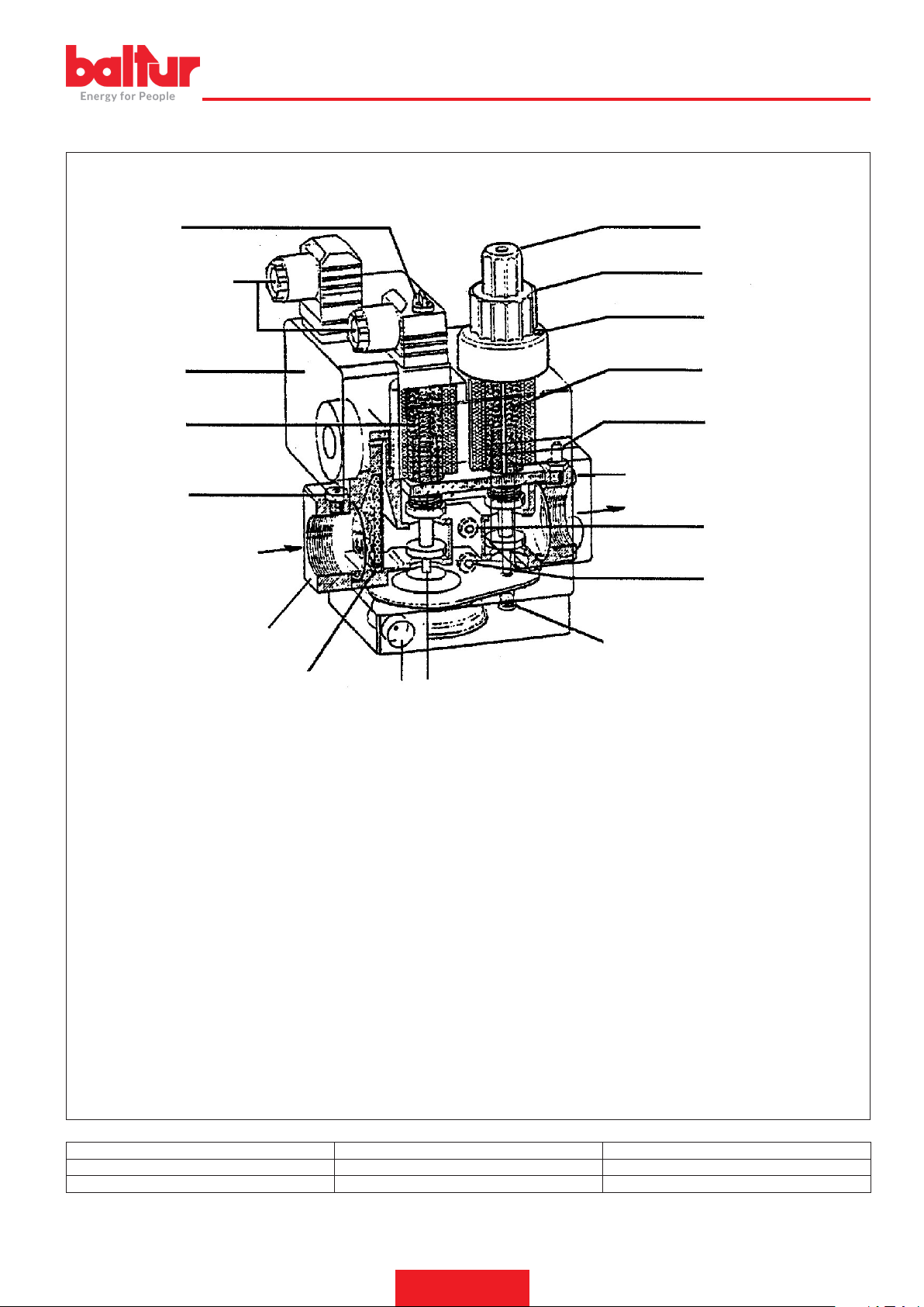
COMBINED DUNGS GAS VALVE (MONOBLOCK) MOD. MB-DLE ... B01
0002910301
1 2
ENGLISH
14
6
13
A
B
15
12
11
3
4
5
7
17
8 (Pa)
9 (Pa)
16
10
A Electrical connections
B Flow direction
1 Acces to stabilizer regulating screw
2 Access knob for controlling the ignition ow rate regulator
3 Locking screw for regulating knob
4 Locking screw
5 Main valve (two-phase opening)
6 Safety valve (quick)
7 Pressure port (for checking the valve outlet pressure)
8 Stabilizer outlet pressure port (Pa)
9 Valve inlet pressure port (Pe)
Valve model Max intake pressure (PE) mbar Stabiliser pressure adjustable at outlet (PA) mbar
MB …403 B01 S 20 200 from 4 to 20
MB … … B01 S 20 360 from 4 to 20
10 Pressure stabilizer
11 Pressure stabiliser bleed
12 Inlet lter
13 Valve inlet pressure port
14 Minimum pressure switch
15 Input ange
16 Tappo
17 Outlet ange
17 / 28
0006160053_201912
Page 48

ENGLISH
The DUNGS MB-DLE... gas valve unit is made up of:
• A safety valve which closes opens rapidly (6).
• A main valve which opens in two stages (5). The rst opening stage
occurs rapidly (release) and can be adjusted unscrewing the knob
(2) and inserting it overturned on the underlying adjusting pin. The
+ and - symbols on the valve head indicate the direction in which
the knob should be turned to change gas ignition ow rate (rst
valve opening stage). Rotating in a clockwise direction, the ignition
delivery diminishes; rotating in an anti-clockwise direction, the de-
livery increases. The complete stroke from zero to the maximum is
slightly more than three turns (40% of the total opening), and vice
versa. When the rst opening stage has taken place, the valve continues to open slowly and takes 15 seconds to reach the maximum
open position. To adjust the desired maximum delivery, loosen the
screw with locking protruding head (4) and turn the knob (3). Do
not tamper with the painted screw. Turn in a clockwise direction
to reduce delivery and in anti-clockwise direction to increase it. It
should be pointed out that when the regulating knob is turned, the
end-of-the-run which limits the operating of the valve moves; there-
fore, when the knob has been turned until it reaches the - sign, the
valve will not open and the burner will not ignite. To get ignition, it
is necessary to turn the knob in an anti-clockwise direction towards
the + sign. The complete run from zero to maximum and vice versa
is nearly six turns of the knob. This adjusting operation (for maximum and ignition output) must be carried out without forcing the
corresponding end of stroke.
• The pressure stabiliser (10) can be adjusted (see table) using the
screw which can be accessed sliding the cover (1) to one side. The
complete run from the maximum to the position and vice versa is
about 80 turns. Do not force against the end-of-the-run positions.
Around the access opening there are arrows with symbols indica-
ting the rotation direction for pressure increase (clockwise) or de-
crease (anti-clockwise). This stabilizer creates a hermetic closure
between the "upstream" and "downstream" sections when there is
no ow. Different springs to obtain different pressure value from
those described above are not foreseen. To regulate the pressure
stabilizer, connect a water manometer to the rubber tube holder
installed on the tap (8) in correspondence with the exit of the stabilizer (Pa). |bb|
• The inlet lter (12) can be accessed for cleaning removing one of
the two side closing plates.
• Minimum pressure switch (14). For adjusting remove the transpa-
rent cover and operate the black knob. The reference mark is a
small rectangle on the yellow disk around which the adjusting knob
rotates.
• At the inlet, a tting (13) has been installed on the connection an-
ge to measure the inlet pressure. At the connection ange outlet,
there is also a tting (7) to measure the outlet pressure.
• The side pressure ttings (9), indicated as Pe, are in communication with the inlet pressure.
• The side pressure taps (8) indicated as Pa, are used to measu-
re the pressure coming out of the stabilizer. It is useful to know,
that the pressure coming out of the valve unit (7) corresponds to
the pressure regulated by the stabilizer and is reduced in order to
overcome the crossing resistance of the principle valve (5). The
valve crossing resistances depend on the opening of the valve re-
gulated by the knob (3) through which the end-of-stroke position
is adjusted. |b|To regulate the pressure stabilizer, connect a water
manometer to the rubber tube holder installed on tap (8) in correspondence to the stabilizer exit (Pa).|b|
• The holes of the pressure stabilizer bleed (11) should be free and
to ensure a proper operation.
SUGGESTIONS FOR ADJUSTING THE GAS VALVE
• Connect a water manometer to the pressure tap Pa (8) to measure
the pressure coming out of the stabilizer.
• Put the gas delivery regulators for ignition (2) and for maximum
delivery (3) in the positions presumed necessary for the delivery
desired. Also open the combustion air regulator.
• Turn on the burner.
• With the burner on, operate under the cover (1) on the adjusting
screw of the gas and pressure stabiliser and adjust pressure to the
value considered necessary to obtain the desired output, approx.
40-70 mm. W.C. when the maximum output regulator (3) is in the
maximum opening position.
• Put the ignition ow regulator (2) in the position considered necessary to obtain ignition with the minimum possible delivery.
CAUTION / WARNINGS
With irregular ignitions, adjust the pressure to the stabiliser (8)
at 20 mbar.
18 / 28
0006160053_201912
Page 49
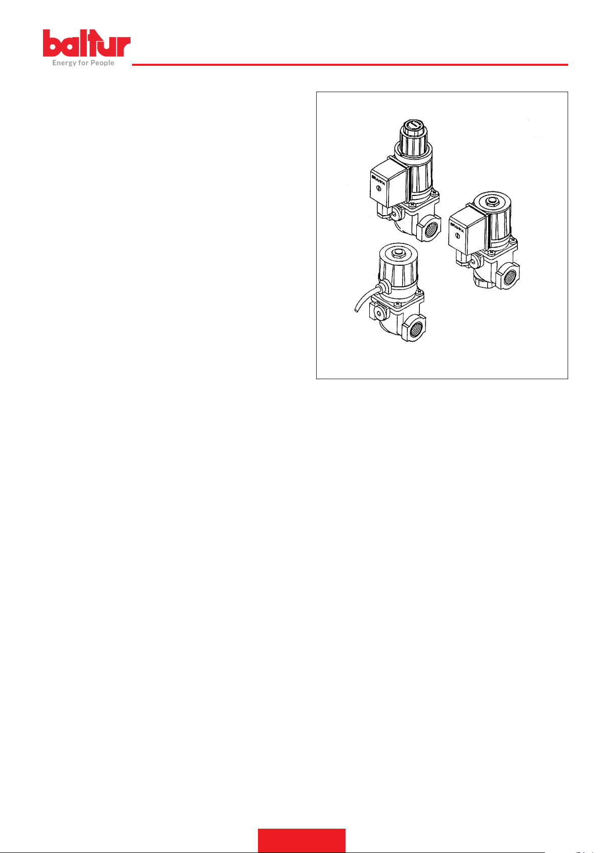
BRAHMA SOLENOID VALVE MOD. EG 12*... AND E6G* FOR
GAS BURNERS (LOW PRESSURE)
ENGLISH
DESCRIPTION
Code EG 12*S... identies a type of valve that is normally with quick
closure, quick or slow opening with a quick release that can be adjusted for the initial ow rate.
Version EG 12*S... (g. 1) and EG 12*L are powered with alternating
current but with an integrated rectier circuit, the coil is powered with
direct current.
All EG 12*... solenoid valves have two ttings for the installation of
pressure ports.
Each valve is tted with an upstream lter to prevent the inltration of
solid particles with size larger than 1 mm.
Solenoid valve EG 12*SR... (g. 2) differs from EG 12*S... due to a
downstream device that regulates the ow rate.
Solenoid valve EG 12*L... (g. 3) allows the burner to be ignited progressively, as its opening is delayed by a specic hydraulic damper in
direct contact with the moving element.
The solenoid valve EG 12*L... makes it possible to regulate the opening time and the quick release for the initial ow rate.
The maximum ow rate can be regulated by adjusting the damper
block.
TECHNICAL DATA
Class: A.
unit: 2
Power supply: 110-230 Vac / 50-60 Hz (versions with different power
supplies are also available)
Working temperature: – 10 / + 60° C
Maximum working pressure guaranteed: 500 mbar.
Vertical / horizontal assembly position.
Closure time ≤ 1 s.
Opening time ≤ 1 s.
Class: At working temperature: – 10° C / + 60° C.
Stainless steel spring, Power supply: 230V 50/60 Hz.
Coil coating: PA6 Degree of protection: IP54.
Die-cast aluminium body
Cable glands: PG9.
Fig.3
0002910220d
Fig.2
Fig.1
19 / 28
0006160053_201912
Page 50
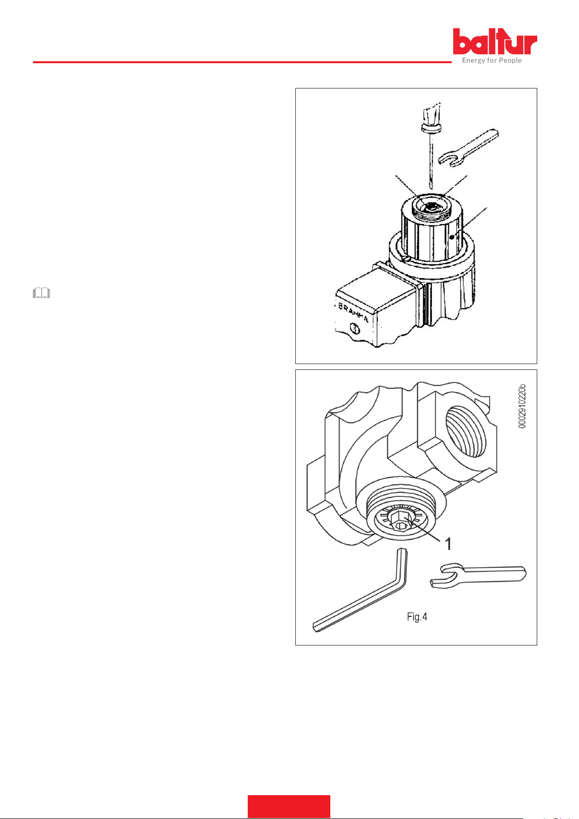
0002910220
ENGLISH
INSTRUCTIONS FOR THE ADJUSTMENT OF SOLENOID VALVES EG 12*L ... AND E 6G*
Flow rate adjustment
To vary the gas ow rate to the burner, adjust block 3 of the time delay
device shown in Fig. 4.
Slacken the cover lock screw (only slacken the screw without paint
seal) and rotate the entire unit.
Turning it clockwise decreases the ow rate and inversely the ow
rate increases.
Maximum adjustment is determined by the regulator screw stop and
a thrust ring, which are both tted inside the sheath.
Solenoid valve opening time adjustment:
It can be obtained using the adjustment screw 1 indicated in g. 4.
Turning it clockwise, the screw tends to block the oil passage hole,
obtaining a long valve opening time. By turning it instead anticlockwi-
se, the opening time decreases as the screw frees the area where
the oil ows.
CAUTION / WARNINGS
The adjustment screw 1 is supplied correctly calibrated by the
manufacturer and, therefore, must not be re-adjusted.
Regulation of the initial ow rate rapid release:
This is done by rotating regulator 2 shown in g. 4.
Turning it with a 6 mm hexagonal wrench in a clockwise direction
decreases the rapid release, turning it anticlockwise increases it.
2
2
1
3
Fig. 4
INSTRUCTIONS FOR THE REGULATION OF THE SOLENOID
VALVE EG12*AR-EG 12*SR
Flow rate regulation:
To be able to vary the gas ow rate, use regulator A and an 8-mm
hex wrench
Or a 4 mm countersunk hexagon wrench.
Turning clockwise, the ow rate decreases. Turning anticlockwise,
the ow rate increases.
20 / 28
0006160053_201912
Page 51

MAINTENANCE
Analyse combustion gases and check that the emission values are
correct at least once a year, in compliance with current law.
• Clean air dampers, the air pressure switch with pressure port and
the relevant pipe, if any.
• Check the electrode condition. Replace them, if necessary.
• Clean the photocell. Replace it, if necessary.
• Have the burner and the chimney cleaned by specialised personnel
(stove repairer); a clean burner is more efcient, lasts longer and
is quieter.
• Check that the fuel lter is clean. Replace it, if necessary.
• Check that all components of the combustion head are in good con-
dition, have not been deformed and are free from deposits deriving
from the installation environment and/or from poor combustion.
• Analyse combustion gases and check emissions values.
ENGLISH
21 / 28
0006160053_201912
Page 52

ENGLISH
MAINTENANCE TIME
Part description Action to be performed Gas
COMBUSTION HEAD
ELECTRODES
FLAME DISC INTEGRITY VISUAL CHECK FOR ANY DEFORMATIONS, CLEANING, YEARLY
IONISATION PROBE
COMBUSTION HEAD COMPO-
NENTS
INSULATING GASKET SEAL VISUAL INSPECTION AND POSSIBLE REPLACEMENT YEARLY
GAS DELIVERY COUPLING
SEAL
AIR GRILLE/DAMPERS CLEANING YEAR
AIR DAMPER BEARINGS GREASING, (Note: apply only on burners with bearings requiring lubrication) YEAR
FAN FAN AND SCROLL CLEANING, DRIVE SHAFT GREASING YEAR
AIR PRESSURE SWITCH CLEANING YEAR
AIR PRESSURE PORT AND
PIPES
FLAME SENSOR CLEANING YEAR
GAS PRESSURE SWITCH FUNCTIONAL INSPECTION YEAR
ELECTRIC MOTORS COOLING FAN CLEANING, BEARING NOISE CHECK YEAR
MECHANICAL CAM CHECK OF WEAR AND OPERATION, GREASING OF SLIDING BLOCK AND SCREWS YEAR
LEVERS/TIE-RODS/BALL
JOINTS
ELECTRICAL SYSTEM CHECK OF CONNECTIONS AND TERMINAL TIGHTENING YEAR
INVERTER COOLING FAN CLEANING AND TERMINAL TIGHTENING YEAR
CO PROBE CLEANING AND CALIBRATION YEAR
O2 PROBE CLEANING AND CALIBRATION YEAR
COMBUSTION HEAD EX-
TRACTION KIT
GAS FILTER REPLACING THE FILTERING ELEMENT YEAR
HYDRAULIC/GAS SEALS CHECK OF ANY LEAKAGES YEAR
CO CONTROL COMPARISON WITH VALUES RECORDED AT SYSTEM START-UP YEAR
CO2 CONTROL COMPARISON WITH VALUES RECORDED AT SYSTEM START-UP YEAR
BACHARACH SMOKE INDEX
CONTROL
NOX CONTROL COMPARISON WITH VALUES RECORDED AT SYSTEM START-UP YEAR
IONISATION CURRENT CON-
TROL
SMOKE TEMPERATURE
CONTROL
GAS PRESSURE REGULATOR PRESSURE MEASURED AT START-UP YEAR
VISUAL INSPECTION OF THE INTEGRITY OF CERAMICS. TIP GRINDING, CHECK DISTANCE,
CHECK ELECTRICAL CONNECTION
VISUAL INSPECTION OF THE INTEGRITY OF CERAMICS. TIP GRINDING, CHECK DISTANCE,
CHECK ELECTRICAL CONNECTION
INTEGRITY VISUAL CHECK FOR ANY DEFORMATIONS, CLEANING, YEARLY
SEAL VISUAL INSPECTION AND POSSIBLE REPLACEMENT YEARLY
AIR LINE
CLEANING YEAR
SAFETY COMPONENTS
VARIOUS COMPONENTS
CHECK OF ANY WEAR, COMPONENT LUBRICATION YEAR
CHECKING WEAR AND OPERATION YEAR
FUEL LINE
COMBUSTION PARAMETERS
COMPARISON WITH VALUES RECORDED AT SYSTEM START-UP n.a.
COMPARISON WITH VALUES RECORDED AT SYSTEM START-UP YEAR
COMPARISON WITH VALUES RECORDED AT SYSTEM START-UP YEAR
YEARLY
YEARLY
IMPORTANT
In case of heavy-duty operation or when using special fuels, the maintenance intervals must be reduced adapting them to the real operating conditions, according to the indications of the maintenance technician.
22 / 28
0006160053_201912
Page 53

ENGLISH
EXPECTED LIFESPAN
The expected lifespan of burners and relevant components depends very much from the type of application on which the burner is installed, from
cycles ,of delivered power, from the conditions of the environment in which it is located, from maintenance frequency and mode, etc.
Standards about safety components provide for a project expected lifespan expressed in cycles and/or years of operation.
Such components ensure the correct operation in standard (*) operating conditions, with periodic maintenance according to the instructions
contained in the manual.
The table below shows the project expected lifespan of the main safety components; approximately, operating cycles correspond to the burner
activations.
|b|When this expected lifespan limit has almost been reached the component must be replaced with an original spare part |bb|.
IMPORTANT
warranty conditions (laid down in contracts and/or delivery or payment notes, if necessary) are independent and do not refer to the
expected lifespan stated below.
(*) “Normal” operating conditions means applications on water boilers and steam generators or industrial applications compliant with the standard
EN 746, in environments with temperatures within the limits provided for in this manual and with pollution degree 2 in compliance with annex M
of the standard EN 60335-1.
Safety component
Control box 250 000 10
Flame sensor (1) n.a. 10,000 operating hours
Seal control 250 000 10
Gas pressure switch 50 000 10
Air pressure switch 250 000 10
Gas pressure regulator (1) n.a. 15
Gas valves (with seal check) Until the rst seal fault signal
Gas valves (without seal check) ( 2) 250 000 10
Servomotors 250 000 10
Air fan impeller 50,000 activations 10
Operating cycles Years of operation
Project expected lifespan
(1) The characteristics can degrade over time; during the annual maintenance the sensor must be checked and in case of ame signal degradation must be replaced.
(2) Using normal mains gas.
23 / 28
0006160053_201912
Page 54

ENGLISH
SPECIFICATIONS FOR PROPANE USE
• Operating costs approximate assessment;
- 1 m3 of liquid gas in gaseous stage has a lower heating capacity, of nearly 25.6 kWh.
- To obtain 1 cu.m of gas, about 2 kg of liquid gas are needed,
i.e. about 4 litres of liquid gas.
• Safety provisions
• Liquid propane gas (L.P.G.) in the gaseous form has a greater specic weight than air (specic weight relative to air = 1.56 for propane), which means it does not disperse in air like natural gas, which
has a lower specic weight than air (specic weight of natural gas
relative to air = 0.60), but precipitates and spreads out at ground
level (as if it were a liquid). Summing up the concepts we deem
most relevant r the use of LPG
• Liqueed petroleum gas (L.P.G.) burners and/or boilers may be
used only in premises located above ground level and certied
toward free spaces. Installations using liquid gas are not allowed in
underground or semi-underground premises.
• Rooms where liquid gas is used must have ventilation inlets without
closing devices, located on external walls, in compliance with the
local exiting rules.
• |b|Carrying out the propane gas system to ensure correct, safe
operation.|bb|
Natural gasication from sets of cylinders or a tank can be used only
in low power systems. Gas supply capacity on the basis of tank size
and minimum outdoor temperature are shown in the table below, as
an approximate indication only.
Minimum
tempera-
ture
Tank 990 l.
Tank
3000 l.
Tank
5000 l.
- 15 °C - 10 °C - 5 °C - 0 °C + 5 °C
1.6 Kg/h 2.5 Kg/h 3.5 Kg/h 8 Kg/h 10 Kg/h
2.5 Kg/h 4.5 Kg/h 6.5 Kg/h 9 Kg/h 12 Kg/h
4 Kg/h 6.5 Kg/h 11.5 Kg/h 16 Kg/h 21 Kg/h
DANGER / ATTENTION
The maximum and minimum power (kW) of the burner refers
to natural gas which is more or less the same as with propane.
• |b|Combustion control|bb|
To keep consumption down and mainly to prevent serious problems,
regulate the combustion using the specic instruments. It is absolutely essential to check that the percentage of carbon monoxide (CO)
does not exceed the maximum permitted value by the local existing
regulation (use a combustion analyser or other similar instrument).
• |b|Burner;|bb|
The burner must be ordered specically for use with liquid gas
(L.P.G.) so that it is equipped with gas valves of sufcient dimen-
sions to ensure correct ignition and gradual adjustment. We provide
valves with size suitable for a supply pressure starting from approx.
300 mm mbar. You suggest checking the burner gas pressure by
using a pressure gauge.
0006160053_201912
24 / 28
Page 55
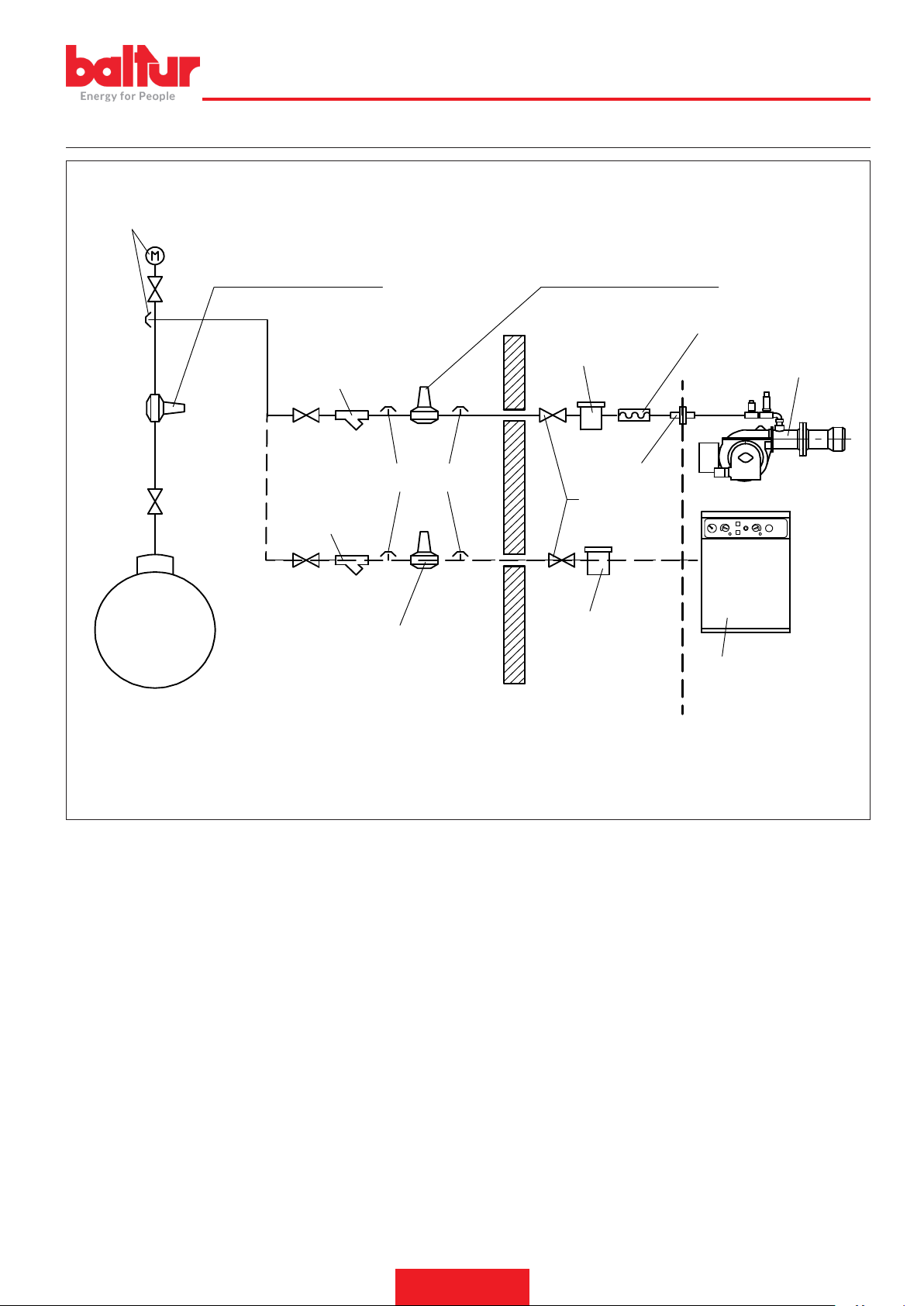
8721_2
ENGLISH
BLOCK DIAGRAM ILLUSTRATING THE PRINCIPLE OF L.P.G. PRESSURE REDUCTION IN TWO STAGES FOR BURNER OR BOILER
Pressure gauge and pressure intake
1st step reducer
Output ~ 1.5 bar
Flow rate ~ double the maximum required by the user
2nd step reducer
Output ~ 30 hPa (mbar)
Flow rate ~ double the maximum required by the user
Vibration-proof joint
LPG tank
Y lter
Pressure intake
Y lter
2nd step reducer
Output ~ 30 hPa (mbar)
Flow rate ~ double the maximum required by
the user
TO BE CARRIED OUT BY THE INSTALLER
Filter
Ball cock
Burner
Pipe tting
Filter
Free-standing or wall-
mounted boiler
SUPPLIED BY THE MANUFACTURER
25 / 28
0006160053_201912
Page 56

ENGLISH
INSTRUCTIONS FOR DETERMINING THE CAUSE LEADING TO IRREGULARITIES IN THE OPERATION AND THEIR ELIMINATION
IRREGULARITY
Appliance locks out due to no ame
(red light lit).The fault is in the ame
control device.
POSSIBLE CAUSE
1 Disturbance to ionization current from the
ignition transformer.
2 Flame sensor (ionization probe) inef-
cient.
3 Flame sensor (ionisation probe) position
incorrect.
4 Ionization probe or relative ground cable.
5 Electrical connection cut-off by ame
sensor.
6 Inefcient draught or fumes passage
blocked.
7 Flame disk or combustion heads dirty or
worn.
8 Equipment fault.
9 No ionization.
REMEDY
1 Invert the ignition transformer power supply
(230V side) and check using an analogue
micro-ammeter.
2 Replace the ame sensor.
3 Correct the position of the ame sensor, and
then check its efciency by connecting the
analogue micro-ammeter.
4 Check visually and using the instrument.
5 Restore the connection.
6 Ensure that the boiler fumes passage and
chimney connection are free.
7 Visually check and replace, if necessary.
8 Replace it.
9 If the “earth” of the equipment is not efcient,
do not check the ionization current.Check
the efciency of the “earth” at the terminal
concerned in the equipment and at the “earth”
connection of the electric system.
The burner goes into “lock-out”, gas
ows, but there is no ame (red light
on).Fault in ignition circuit.
The burner goes into “lock-out”, gas
ows, but there is no ame (red light
on).
1 Fault in ignition circuit
2 Ignition transformer cable discharges to
earth.
3 Ignition cable disconnected.
4 Ignition transformer is faulty.
5 The distance between electrode and
ground is incorrect.
6 Insulator dirty, so electrode discharges to
ground.
1 Air/gas ratio incorrect.
2 Gas pipe has not been properly bled of air
(in the case of rst ignition).
3 The gas pressure is insufcient or exces-
sive.
4 Air ow between disk and head too nar-
row.
1 Check the ignition transformer power supply
(230V) and high voltage circuit (electrode to
earth or isolator broken under locking termi-
nal).
2 Replace it.
3 Connect it.
4 Replace it.
5 Position it at the correct distance.
6 Clean or change the insulator or electrode.
1 Correct the air/gas ratio (there is probably too
much air or very little gas)
2 Bleed the gas pipe again, with due caution.
3 Check the maximum gas pressure value at the
time of ignition (use a water pressure gauge,
if possible).
4 Adjust the disk/head opening.
26 / 28
0006160053_201912
Page 57
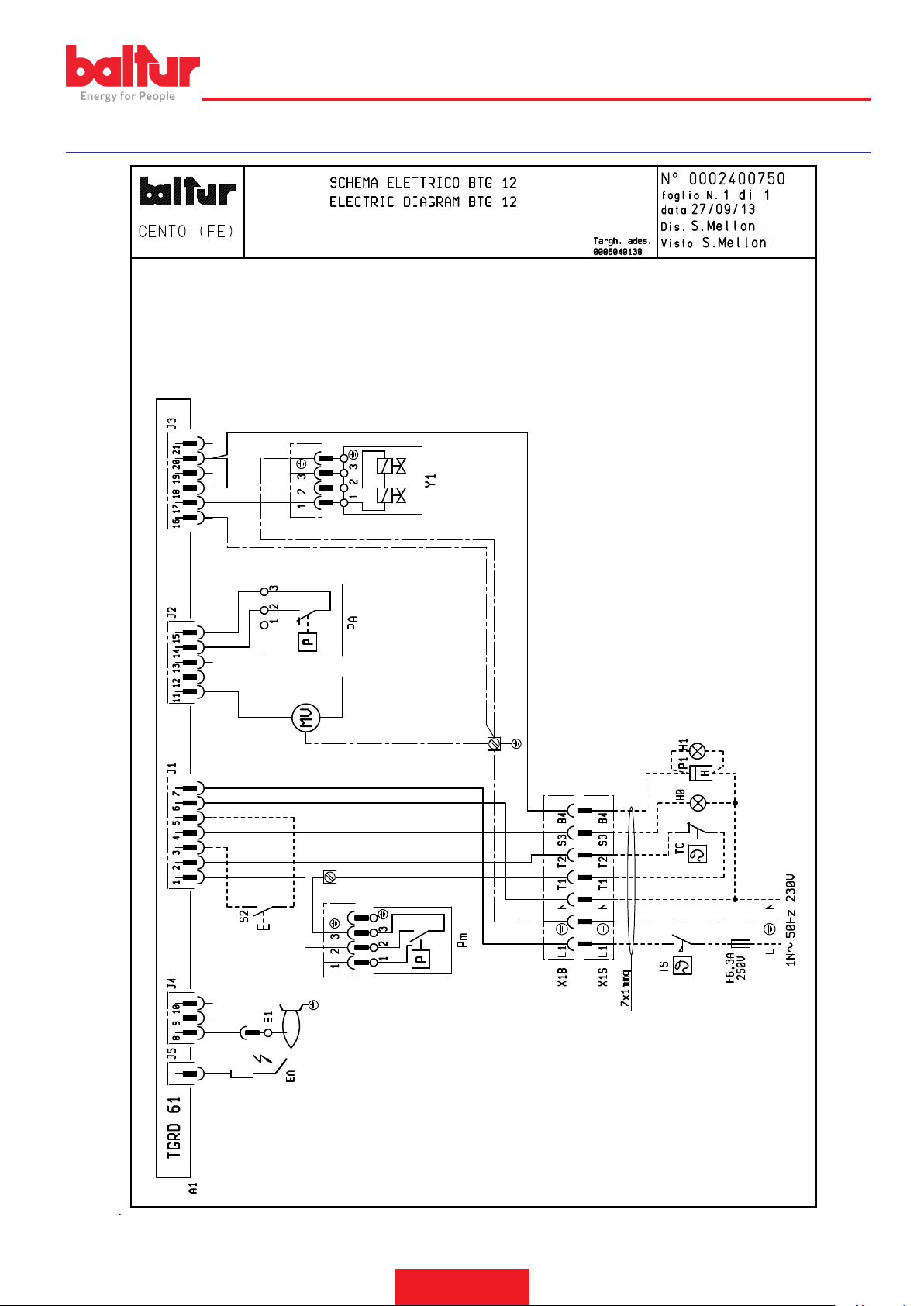
WIRING DIAGRAMS
ENGLISH
27 / 28
0006160053_201912
Page 58

ENGLISH
A1 CONTROL BOX
B1 Flame sensor
Y1/Y2 1st / 2nd STAGE SOLENOID VALVES
H0 EXTERNAL LOCK INDICATOR LIGHT/ AUXILIARY HEATING
ELEMENT OPERATION LAMP
H1 OPERATION INDICATOR LIGHT
P1 “HOUR METER“
PA AIR PRESSURE SWITCH
Pm MINIMUM PRESSURE SWITCH
MV FAN MOTOR
S2 RELEASE BUTTON
TC BOILER THERMOSTAT
TS SAFETY THERMOSTAT
X1B/S POWER SUPPLY CONNECTOR
L1 - L2- L3 Phases
N - Neutral
Ground
Minimum ionisation current 1.5 μA
28 / 28
0006160053_201912
Page 59

Page 60

BALTUR S.P.A.
Via Ferrarese, 10
44042 Cento (Fe) - Italy
Tel. +39 051-6843711
Fax. +39 051-6857527/28
www.baltur.it
Il presente catalogo riveste carattere puramente indicativo. La casa, pertanto, si riserva ogni possibilità di modica dei dati tecnici e di quant'altro in esso riportato.
Information contained in this catalogue is not binding. The manufacturer reserves the right to change the technical data and any other data it contains.
 Loading...